

Suzuki vitara content1of2 Diagram
IMPORTANT
W ARNING/CAUTION/NOTE
Please read this manual and follow its instructions
carefully. To emphasize special information, the
words WARNING, CAUTION and NOTE have special meanings. Pay special attention to the messages
highlighted by these signal words.
WARNING:
Indicates a potential hazard that could result
in death or injury.
CAUTION:
Indicates a potential hazard that could result
in vehicle damage.
NOTE:
Indicates special information to make maintenance easier or instructions clearer.
WARNING:
This service manual is intended for authorized
SUZUKI dealers and qualified service mechanics only. Inexperienced mechanics or
mechanics without the proper tools and
equipment may not be able to properly perform the services described in this manual.
Improper repair may result in injury to the mechanic and may render the vehicle unsafe for
the driver and passengers.
WARNING:
For vehicles equipped with a Supplemental
Restraint (Air Bag) System:
Service on and around the air bag system
components or wiring must be performed
only by an authorized SUZUKI dealer.
Refer to “Air Bag System Components and
Wiring Location View” under “General Description” in air bag system section in order
to confirm whether you are performing service on or near the air bag system components or wiring. Please observe all WARNINGS and “Service Precautions” under “OnVehicle Service” in air bag system section
before performing service on or around the
air bag system components or wiring. Failure to follow WARNINGS could result in
unintentional activation of the system or
could render the system inoperative. Either
of these two conditions may result in severe
injury .
If the air bag system and another vehicle
system both need repair, SUZUKI recommends that the air bag system be repaired
first, to help avoid unintended air bag system activation.
Do not modify the steering wheel, instru-
ment panel or any other air bag system component (on or around air bag system components or wiring). Modifications can adversely affect air bag system performance and
lead to injury.
If the vehicle will be exposed to tempera-
tures over 93 C (200 F) (for example, during
a paint baking process), remove the air bag
system components (air bag (inflator) module, sensing and diagnostic module (SDM),
seat belt pretensioner (if equipped) beforehand to avoid component damage or unintended activation.

FOREWORD
This manual (Volumes 1 and 2) contains procedures for diagnosis, maintenance, adjustments,
minor service operations, replacement of components (Service) and for disassembly and assembly of major components (Unit Repair-Overhaul).
VOLUME 1 contains Chassis, Electrical and Body sections (all sections except engine).
VOLUME 2 contains Engine sections (Sections 6 – 6K).
Applicable model:SQ416/SQ420/SQ625 of and after the vehicle identification number
below.
()
x
JSAFTA03V00150001 JS3TA03V 14150001 2S2GTA03C00470001
()
x
JSAFTA03V10150001 JS3TA52V 14150001 2S2GTA03C10470001
()
x
JSAFTA03V14150001 JS3TL52V 14150001 2S2GTA03C16470001
()
x
JSAFTA52V00150001 JS3TD62V 14150001 2S3TA03C 16100001
()
x
JSAFTA52V10150001 2S3TA52C 16100001
()
x
JSAFTA52V14150001 2S2GTA52C00470001
()
x
JSAFTL52V00150001 2S2GTA52C10470001
()
x
JSAFTL52V10150001
()
x
JSAFTL52V14150001
()
x
JSAFTD62V00150001
()
x
JSAFTD62V10150001
()
x
JSAFTD62V14150001
()
x
()
x
()
x
()
x
()
x
()
x
()
x
()
x
()
x
()
x
()
x
()
x
The contents are classified into sections each of which is given a section number as indicated
in the T able of Contents on next page. And on the first page of each individual section is an index
of that section.
This manual should be kept in a handy place for ready reference of the service work.
Strict observance of the so specified items will enable one to obtain the full performance of the
vehicle.
When replacing parts or servicing by disassembling, it is recommended to use SUZUKI genuine
parts, tools and service materials (lubricant, sealants, etc.) as specified in each description.
All information, illustrations and specifications contained in this literature are based on the latest
product information available at the time of publication approval. And used as the main subject
of description is the vehicle of standard specifications among others.
Therefore, note that illustrations may differ from the vehicle being actually serviced.
The right is reserved to make changes at any time without notice.
NOTE:
Refer to the next page for RELATED MANUALS.
OVERSEAS SERVICE DEP AR TMENT
COPYRIGHT SUZUKI MOTOR CORPORATION 2000

RELATED MANUAL
MANUAL NAME MANUAL NO. APPLICABILITY
SQ416/SQ420/SQ625
Unit Repair Manual
SQ416/SQ420/SQ625
Wiring Diagram Manual
SQ416/SQ420/SQ625
Service Manual
SQ416/SQ420/SQ625
Wiring Diagram Manual
99501-65D01-xxx Transmission, Transfer and Differentials
(Front and Rear) of SQ series.
99512-65D10-015 Applicable model mentioned in FOREWORD
of this manual.
99500-65D00-xxx
99512-65D01-015
Vehicles before the vehicle identification number
mentioned in FOREWORD of this manual.
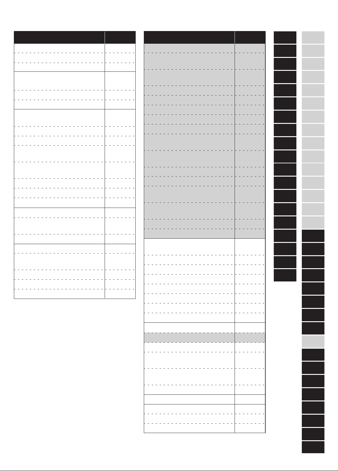
TABLE OF CONTENTS TABLE OF CONTENTS SECTIONSECTION
0A
6
GENERAL INFORMATION
General Information
Maintenance and Lubrication
HEATING AND AIR
CONDITIONING
Heater and Ventilation
Air Conditioning
STEERING, SUSPENSION,
WHEELS AND TIRES
Front End Alignment
Power Steering (P/S) System
Steering Wheel and Column
(Not Equipped with Air Bag)
Air Bag Steering Wheel
and Column
Front Suspension
Rear Suspension
Wheel and Tires
DRIVE SHAFT/PROP. SHAFT
Front Drive Shaft/Shaft
Bearing, Oil Seal
Propeller Shaft
BRAKES
Brake Pipe/Hose/Master
Cylinder
Front Brakes
Parking and Rear Brakes
Antilock Brake System
0A
0B
1A
1B
3
3A
3B1
3C
3C1
3D
3E
3F
4A2
4B
5
5A
5B
5C
5E1
ENGINE
General Information and
Diagnosis (G16/J20)
General Information and
Diagnosis (H25)
Engine Mechanical (G16)
Engine Mechanical (H25)
Engine Mechanical (J20)
Engine Cooling
Engine Fuel
Engine and Emission Control
System (SFI for G16/J20)
Engine and Emission Control
System (SFI for H25)
Ignition System (G16)
Ignition System (J20/H25)
Cranking System
(Reduction Type)
Cranking System
(No-Reduction Type)
Charging System
Exhaust System
TRANSMISSION, CLUTCH
AND DIFFERENTIAL
Manual Transmission (Type 1)
Manual Transmission (Type 2)
Automatic Transmission
Clutch (Hydraulic Type)
Transfer
Differential (Front)
Differential (Rear)
BODY ELECTRICAL SYSTEM
Wiring Diagram
Lighting System
Instrumentation/Driver
Information
Windows, Mirrors, Security
and Lock
Immobilizer Control System
BODY SERVICE
RESTRAINT SYSTEM
Seat Belt
Air Bag System
6
6-1
6A1
6A2
6A4
6B
6C
6E1
6E2
6F1
6F2
6G
6G1
6H
6K
7A
7A1
7B1
7C1
7D
7E
7F
8
8A
8B
8C
8D
8G
9
10
10A
10B
NOTE:
The screen toned Sections 6 – 6K are included in Volume 2 and Section 8A is in Wiring
Diagram Manual.
0B
1A
1B
3
3A
3B1
3C
3C1
3D
3E
3F
4A2
4B
5
5B
5C
5E1
6-1
6A1
6A2
6A4
6B
6C
6E1
6E2
6F1
6F2
6G
6G1
6H
6K
7A5A
7A1
7B1
7C1
7D
7E
7F
8
8A
8B
8C
8D
8G
9
10
10A
10B

GENERAL INFORMATION 0A-1
SECTION 0A
GENERAL INFORMATION
CONTENTS
HOW TO USE THIS MANUAL 0A- 2. . . . . . . . . . . . . . . . . . . . . . . . . . . . . . . . . . . . . . . . . . . . . . . . . . . . . . . . . . . . . . .
PRECAUTIONS 0A- 3. . . . . . . . . . . . . . . . . . . . . . . . . . . . . . . . . . . . . . . . . . . . . . . . . . . . . . . . . . . . . . . . . . . . . . . . . . . .
Precautions for Vehicle Equipped with a Supplemental Restraint (Air Bag) System 0A- 3. . . . . . . . . . . . . . . .
Diagnosis 0A- 3. . . . . . . . . . . . . . . . . . . . . . . . . . . . . . . . . . . . . . . . . . . . . . . . . . . . . . . . . . . . . . . . . . . . . . . . . . . . .
Servicing and Handling 0A- 4. . . . . . . . . . . . . . . . . . . . . . . . . . . . . . . . . . . . . . . . . . . . . . . . . . . . . . . . . . . . . . . . . .
General Precautions 0A- 7. . . . . . . . . . . . . . . . . . . . . . . . . . . . . . . . . . . . . . . . . . . . . . . . . . . . . . . . . . . . . . . . . . . . . .
Precautions for Catalytic Converter 0A- 9. . . . . . . . . . . . . . . . . . . . . . . . . . . . . . . . . . . . . . . . . . . . . . . . . . . . . . . . .
Precautions for Electrical Circuit Service 0A-10. . . . . . . . . . . . . . . . . . . . . . . . . . . . . . . . . . . . . . . . . . . . . . . . . . . . .
Electrical Circuit Inspection Procedure 0A-12. . . . . . . . . . . . . . . . . . . . . . . . . . . . . . . . . . . . . . . . . . . . . . . . . . . . . .
Intermittent and Poor Connection 0A-15. . . . . . . . . . . . . . . . . . . . . . . . . . . . . . . . . . . . . . . . . . . . . . . . . . . . . . . . . . .
Precaution for Installing Mobile Communication Equipment 0A-16. . . . . . . . . . . . . . . . . . . . . . . . . . . . . . . . . . . .
IDENTIFICATION INFORMATION 0A-17. . . . . . . . . . . . . . . . . . . . . . . . . . . . . . . . . . . . . . . . . . . . . . . . . . . . . . . . . . . .
Body Number 0A-17. . . . . . . . . . . . . . . . . . . . . . . . . . . . . . . . . . . . . . . . . . . . . . . . . . . . . . . . . . . . . . . . . . . . . . . . . . . .
Engine Identification Number 0A-17. . . . . . . . . . . . . . . . . . . . . . . . . . . . . . . . . . . . . . . . . . . . . . . . . . . . . . . . . . . . . . .
Transmission Identification Number 0A-17. . . . . . . . . . . . . . . . . . . . . . . . . . . . . . . . . . . . . . . . . . . . . . . . . . . . . . . . .
WARNING, CAUTION AND INFORMATION LABELS 0A-18. . . . . . . . . . . . . . . . . . . . . . . . . . . . . . . . . . . . . . . . . .
VEHICLE LIFTING POINTS 0A-19. . . . . . . . . . . . . . . . . . . . . . . . . . . . . . . . . . . . . . . . . . . . . . . . . . . . . . . . . . . . . . . . .
ABBREVIATIONS MAY BE USED IN THIS MANUAL 0A-21. . . . . . . . . . . . . . . . . . . . . . . . . . . . . . . . . . . . . . . . . . .
METRIC INFORMATION 0A-23. . . . . . . . . . . . . . . . . . . . . . . . . . . . . . . . . . . . . . . . . . . . . . . . . . . . . . . . . . . . . . . . . . . .
Metric Fasteners 0A-23. . . . . . . . . . . . . . . . . . . . . . . . . . . . . . . . . . . . . . . . . . . . . . . . . . . . . . . . . . . . . . . . . . . . . . . . .
Fasteners Strength Identification 0A-23. . . . . . . . . . . . . . . . . . . . . . . . . . . . . . . . . . . . . . . . . . . . . . . . . . . . . . . . . . .
Standard Tightening Torque 0A-24. . . . . . . . . . . . . . . . . . . . . . . . . . . . . . . . . . . . . . . . . . . . . . . . . . . . . . . . . . . . . . . .
0A
0A-2 GENERAL INFORMATION
HOW TO USE THIS MANUAL
1) There is a TABLE OF CONTENTS FOR THE WHOLE MANUAL
on the third page of this manual, whereby you can easily find the
section that offers the information you need. Also, there is a
CONTENTS on the first page of EACH SECTION, where the
main items in that section are listed.
2) Each section of this manual has its own pagination. It is indicated
at the top of each page along with the Section name.
3) The SPECIAL TOOL usage and TORQUE SPECIFICA TION are
given as shown in figure below.
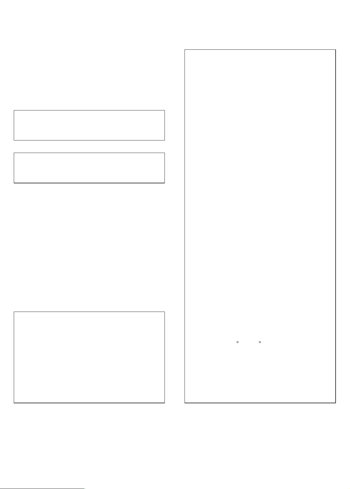
6) Install oil pump. Refer to “Oil pump”.
7) Install flywheel (for M/T vehicle) or drive plate (for A/T vehicle).
Using special tool, lock flywheel or drive plate, and tighten
flywheel or drive plate bolts to specified torque.
1, (c)
1. Flywheel bolts or drive plate bolts for A/T vehicle
Special Tool
(A): 09924-17810
Tightening Torque
(c): 78 N
.
m (7.8 kg-m, 56.0 lb-ft)
4) A number of abbreviations are used in the text.
For their full explanations, refer to “ABBREVIA TIONS MA Y BE
USED IN THIS MANUAL” of this section.
5) The SI, metric and foot-pound systems are used as units in this
manual.
6) DIAGNOSIS are included in each section as necessary.
7) At the end of each section, there are descriptions of SPECIAL
TOOLS, REQUIRED SERVICE MATERIALS and TIGHTENING TORQUE SPECIFICA TIONS that should be used for the
servicing work described in that section.
GENERAL INFORMATION 0A-3
PRECAUTIONS
PRECAUTION FOR VEHICLES EQUIPPED
WITH A SUPPLEMENTAL RESTRAINT
(AIR BAG) SYSTEM
WARNING:
The configuration of air bag system parts are as shown in
the figure. When it is necessary to service (remove, reinstall and inspect) these parts, be sure to follow procedures described in SECTION 10B. Failure to follow proper
procedures could result in possible air bag system activation, personal injury, damage to parts or air bag system
being unable to activate when necessary.
If the air bag system and another vehicle system both
need repair, SUZUKI recommends that the air bag system
be repaired first, to help avoid unintended air bag system
activation.
Do not modify the steering wheel, dashboard, or any other
air bag system components. Modifications can adversely
affect air bag system performance and lead to injury.
If the vehicle will be exposed to temperatures over 93C
(200F) (for example, during a paint baking process), remove the air bag system components beforehand to avoid
component damage or unintended air bag system activation.
1. Air bag wire harness
2. Passenger air bag
(inflator) module
3. SDM
4. DLC
5. Contact coil
6. Driver air bag (inflator)
module
7. Seat belt pretensioner
(if equipped)
DIAGNOSIS
When troubleshooting air bag system, be sure to follow
“DIAGNOSIS” in SECTION 10B. Bypassing these procedures may result in extended diagnostic time, incorrect diagnosis, and incorrect parts replacement.
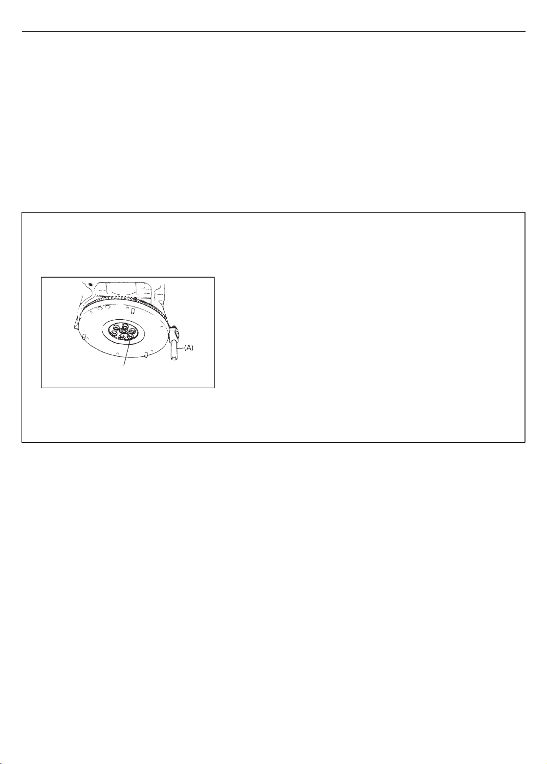
Never use electrical test equipment other than that specified
in this manual.
WARNING:
Never attempt to measure the resistance of the air bag (inflator) modules (driver and passenger) and seat belt pretentioners (driver and passenger). It is very dangerous as the
electric current from the tester may deploy the air bag or activate the pretensioner.
0A-4 GENERAL INFORMATION
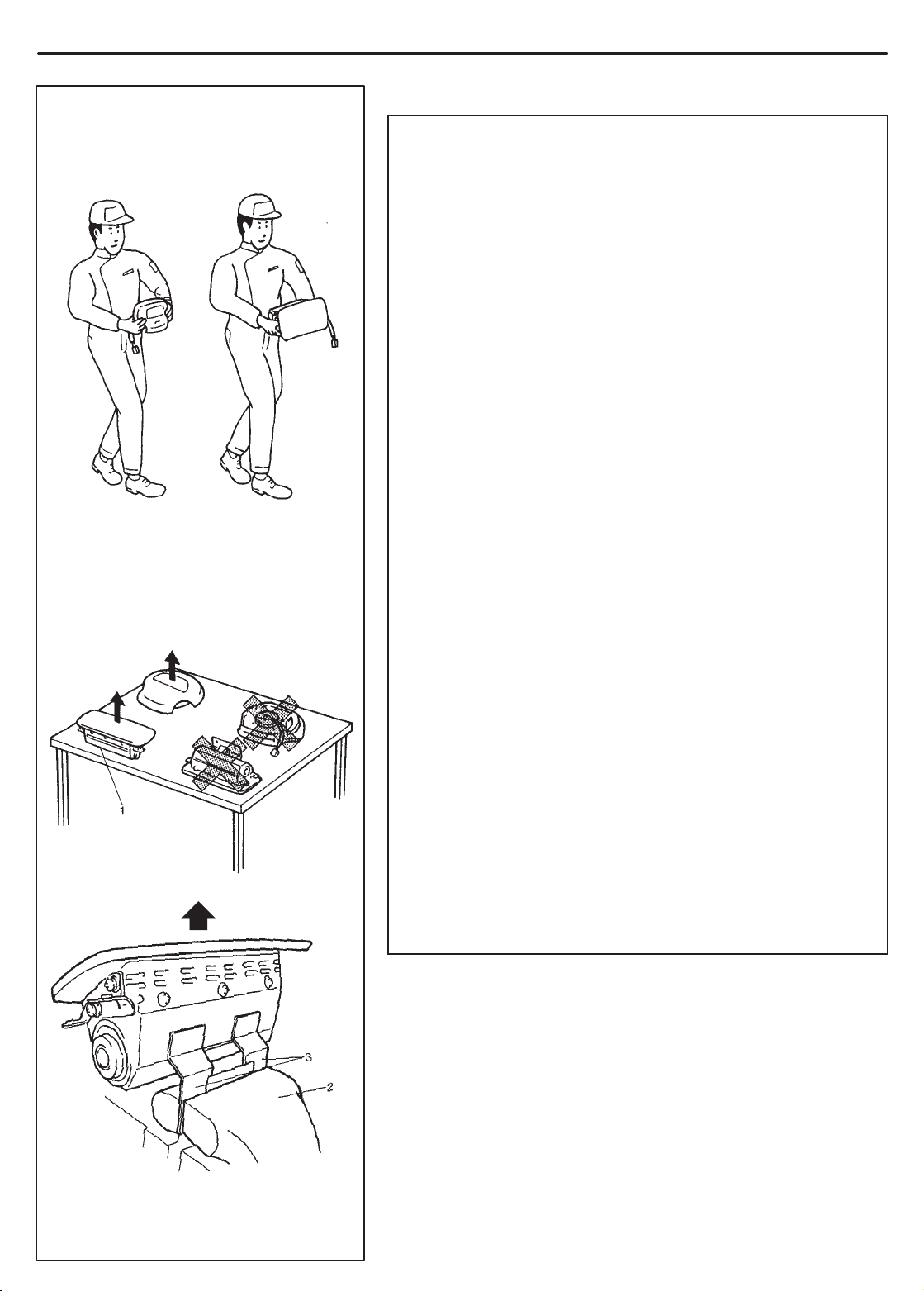
ALWAYS CARRY AIR BAG (INFLATOR) MODULE
WITH TRIM COVER (AIR BAG OPENING) AWAY
FROM BODY.
ALWAYS PLACE AIR BAG (INFLATOR) MODULE
ON WORKBENCH WITH TRIM COVER (AIR BAG
OPENING) UP, AWAY FROM LOOSE OBJECTS.
SERVICING AND HANDLING
WARNING:
Many of service procedures require disconnection of “AIR
BAG” fuse and all air bag (inflator) module(s) from initiator
circuit to avoid an accidental deployment.
Driver and Passenger Air Bag (Inflator) Modules
For handling and storage of a live air bag (inflator) module,
select a place where the ambient temperature below 65C
(150F), without high humidity and away from electric
noise.
When carrying a live air bag (inflator) module, make sure
the bag opening is pointed away from you. In case of an
accidental deployment, the bag will then deploy with minimal chance of injury. Never carry the air bag (inflator)
module by the wires or connector on the underside of the
module. When placing a live air bag (inflator) module on
a bench or other surface, always face the bag up, away
from the surface. As the live passenger air bag (inflator)
module must be placed with its bag (trim cover) facing up,
place it on the workbench with a slit or use the workbench
vise to hold it securely at its lower mounting bracket. This
is necessary so that a free space is provided to allow the
air bag to expand in the unlikely event of accidental deployment. Otherwise, personal injury may result.
Never dispose of live (undeployed) air bag (inflator) mod-
ules (driver and passenger). If disposal is necessary, be
sure to deploy them according to deployment procedures
described in SECTION 10B before disposal.
The air bag (inflator) module immediately after deploy-
ment is very hot. Wait for at least half an hour to cool it off
before proceeding the work.
After an air bag (inflator) module has been deployed, the
surface of the air bag may contain a powdery residue. This
powder consists primarily of cornstarch (used to lubricate the bag as it inflates) and by-products of the chemical
reaction. As with many service procedures, gloves and
safety glasses should be worn.
1. Slit on workbench
2. Workbench vise
3. Lower mounting bracket
GENERAL INFORMATION 0A-5
WARNING:
SDM
During service procedures, be very careful when handling
a Sensing and Diagnostic Module (SDM). Never strike or
jar the SDM.
Never power up the air bag system when the SDM is not
rigidly attached to the vehicle. All SDM and mounting
bracket fasteners must be carefully torqued and the arrow
must be pointing toward the front of the vehicle to ensure
proper operation of the air bag system.
The SDM could be activated when powered while not rigidly attached to the vehicle which could cause deployment
and result in personal injury.
1
1
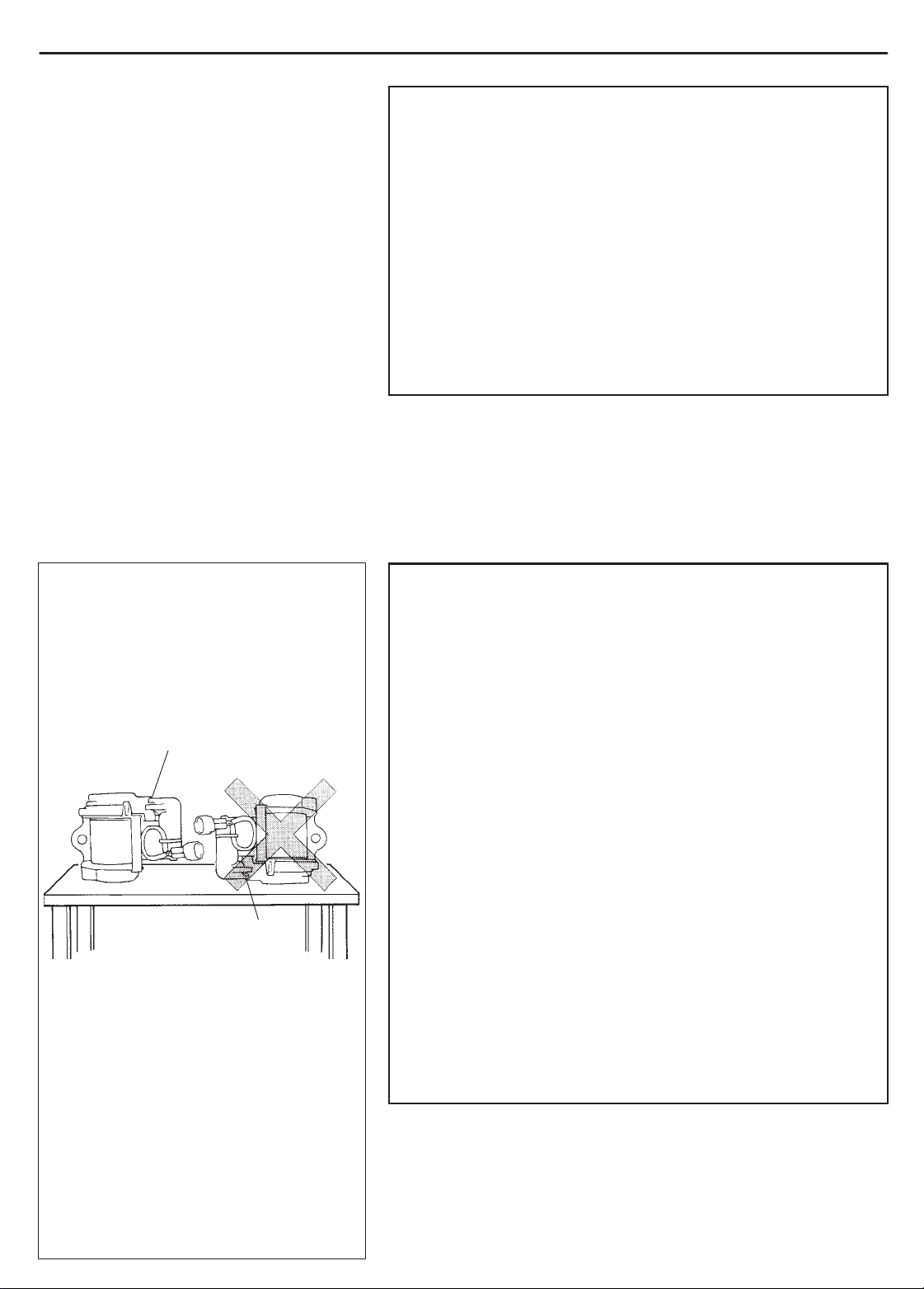
1. Exhaust hole
NG
WARNING:
Driver and Passenger Seat Belt Pretensioners
For handling and storage of a live seat belt pretensioner,
select a place where the ambient temperature below 65C
(150F), without high humidity and away from electric
noise.
Never carry seat belt pretensioner by wire or connector of
pretensioner. When placing a live seat belt pretensioner
on the workbench or some place like that, be sure not to
lay it with its exhaust hole provided side facing down. It is
also prohibited to put something on its face with an exhaust hole or to put a seat belt pretensioner on top of
another. Otherwise, personal injury may result.
Never dispose of live (inactivated) seat belt pretensioners
(driver and passenger). If disposal is necessary, be sure
to activate them according to activation procedures described in SECTION 10B before disposal.
The seat belt pretensioner immediately after activation is
very hot. Wait for at least half an hour to cool it off before
proceeding the work.
With many service procedures, gloves and safety glasses
should be worn to prevent any possible irritation of the
skin or eyes.

0A-6 GENERAL INFORMATION
CAUTION:
Even when the accident was light enough not to cause air
bags to activate, be sure to inspect system parts and other
related parts according to instructions under “Repair and
Inspection Required after an Accident” in SECTION 10B.
When servicing parts other than air bag system, if shocks
may be applied to air bag system component parts, remove those parts beforehand.
When handling the air bag (inflator) modules (driver and
passenger), seat belt pretensioners (driver and passenger) or SDM, be careful not to drop it or apply an impact to
it. If an excessive impact was applied (e.g., dropped from
a height of 91.4 cm (3 feet) or more), never attempt disassembly or repair but replace it with a new one.
When grease, cleaning agent, oil, water, etc. has got onto
air bag (inflator) modules (driver and passenger) or seat
belt pretensioners (drive and passenger), wipe off immediately with a dry cloth.
Air bag wire harness can be identified easily as it is cov-
ered with a yellow protection tube. Be very careful when
handling it.
When an open in air bag wire harness, damaged wire har-
ness, connector or terminal is found, replace wire harness, connectors and terminals as an assembly.
Do not apply power to the air bag system unless all com-
ponents are connected or a diagnostic chart requests it,
as this will set a diagnostic trouble code.
Never use air bag system component parts from another
vehicle.
When using electric welding, be sure to temporarily dis-
able air bag system referring to “Disabling Air Bag System” described in “Service Precautions” under “On-Vehicle Service” in SECTION 10B.
Never expose air bag system component parts directly to
hot air (drying or baking the vehicle after painting) or
flames.
WARNING/CAUTION labels are attached on each part of
air bag system components. Be sure to follow the instructions.
After vehicle is completely repaired, perform “Air Bag
Diagnostic System Check” described in “Diagnosis” in
SECTION 10B.
GENERAL INFORMATION 0A-7
GENERAL PRECAUTIONS
The WARNING and CAUTION below describe some general precautions that you should observe when servicing
a vehicle. These general precautions apply to many of the service procedures described in this manual, and they
will not necessarily be repeated with each procedure to which they apply.
WARNING:
Whenever raising a vehicle for service, be sure to follow the instructions under “VEHICLE LIFTING
POINTS” on SECTION 0A.
When it is necessary to do service work with the engine running, make sure that the parking brake
is set fully and the transmission is in Neutral (for manual transmission vehicles) or Park (for automatic
transmission vehicles). Keep hands, hair, clothing, tools, etc. away from the fan and belts when the
engine is running.
When it is necessary to run the engine indoors, make sure that the exhaust gas is forced outdoors.
Do not perform service work in areas where combustible materials can come in contact with a hot
exhaust system. When working with toxic or flammable materials (such as gasoline and refrigerant),
make sure that the area you work in is well-ventilated.
T o avoid getting burned, keep away from hot metal parts such as the radiator , exhaust manifold, tail-
pipe, muffler, etc.
New and used engine oil can be hazardous. Children and pets may be harmed by swallowing new or
used oil. Keep new and used oil and used engine oil filters away from children and pets.
Continuous contact with used engine oil has been found to cause [skin] cancer in laboratory animals.
Brief contact with used oil may irritate skin. To minimize your exposure to used engine oil, wear a
long-sleeve shirt and moisture-proof gloves (such as dishwashing gloves) when changing engine oil.
If engine oil contacts your skin, wash thoroughly with soap and water. Launder any clothing or rags
if wet with oil, recycle or properly dispose of used oil and filters.
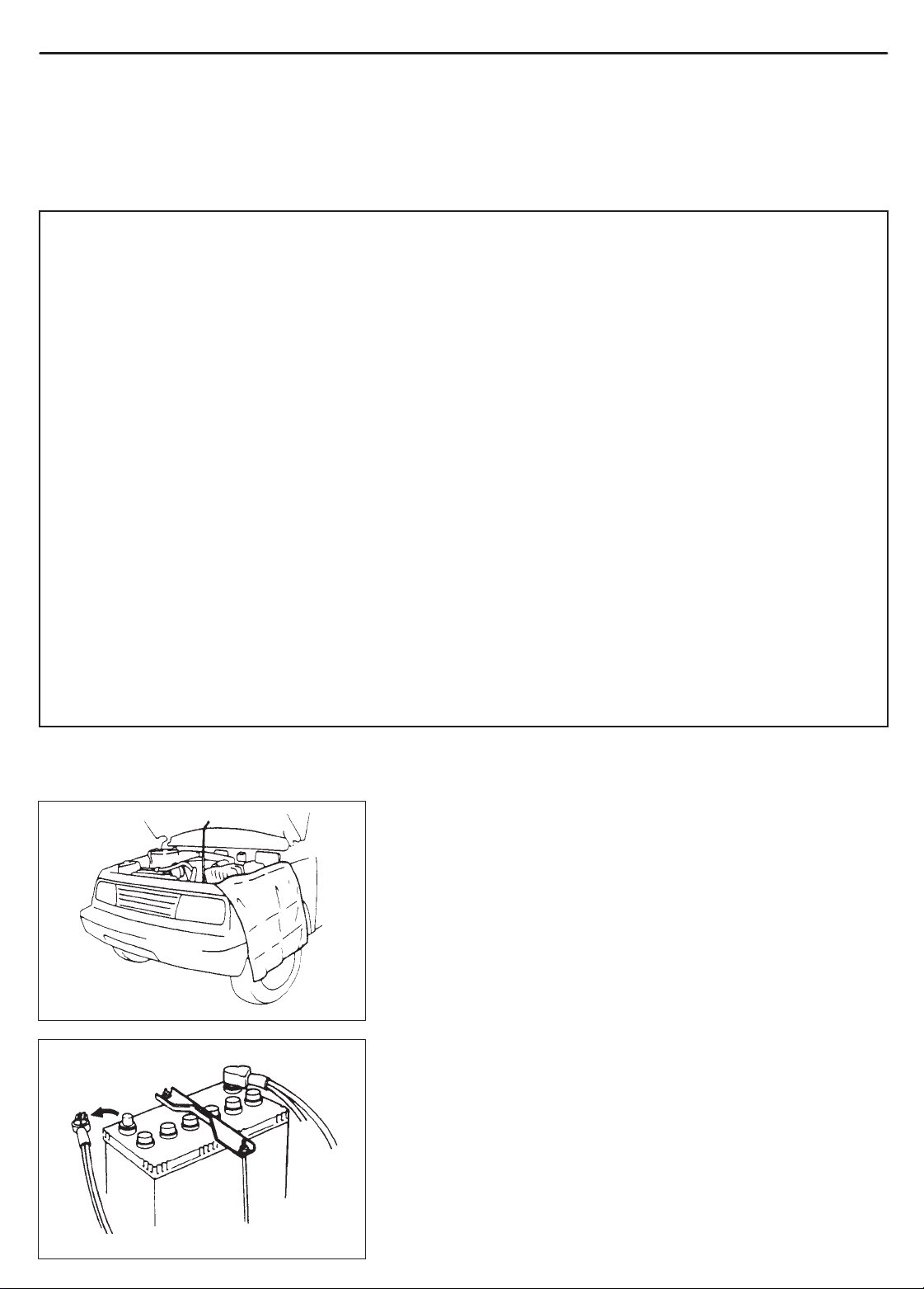
Make sure the bonnet is fully closed and latched before driving. If it is not, it can fly up unexpectedly
during driving, obstructing your view and resulting in an accident.
CAUTION:
Before starting any service work, cover fenders, seats and
any other parts that are likely to get scratched or stained during servicing. Also, be aware that what you wear (e.g, buttons) may cause damage to the vehicle’s finish.
When performing service to electrical parts that does not re-
quire use of battery power, disconnect the negative cable of
the battery.
0A-8 GENERAL INFORMATION
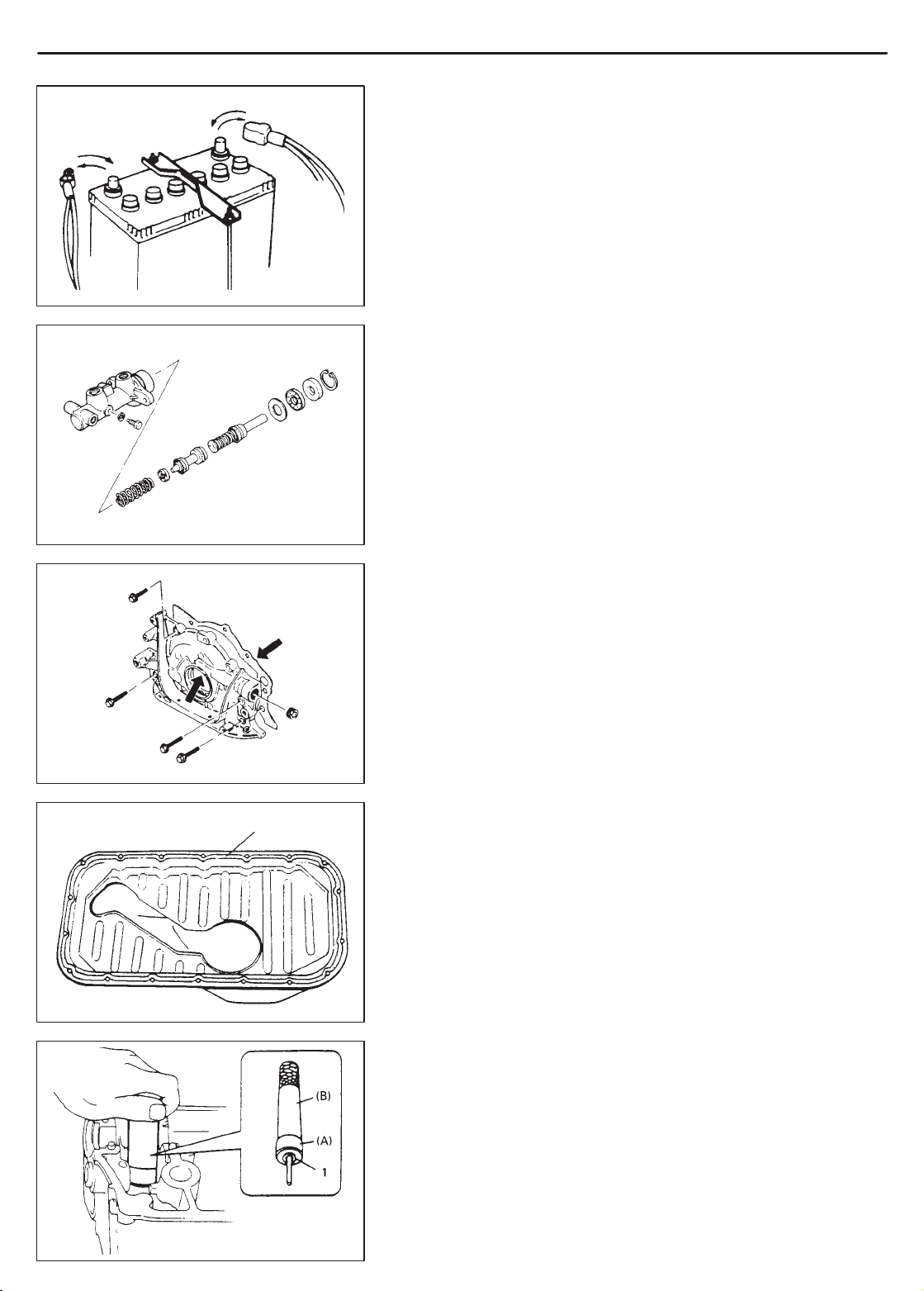
When removing the battery , be sure to disconnect the nega-
tive cable first and then the positive cable. When reconnecting the battery , connect the positive cable first and then the
negative cable, and replace the terminal cover.
When removing parts that are to be reused, be sure to keep
them arranged in an orderly manner so that they may be reinstalled in the proper order and position.
“A”
Whenever you use oil seals, gaskets, packing, O-rings, lock-
ing washers, split pins, self-locking nuts, and certain other
parts as specified, be sure to use new ones. Also, before
installing new gaskets, packing, etc., be sure to remove any
residual material from the mating surfaces.
Make sure that all parts used in reassembly are perfectly
clean.
When use of a certain type of lubricant, bond or sealant is
specified, be sure to use the specified type.
“A”: Sealant 99000-31150
Be sure to use special tools when instructed.
Special Tool
(A):09917-98221
(B):09916-58210
GENERAL INFORMATION 0A-9
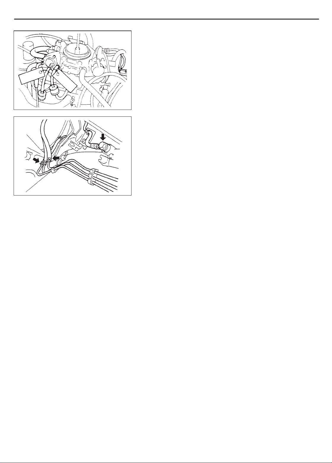
When disconnecting vacuum hoses, attach a tag describing
the correct installation positions so that the hoses can be reinstalled correctly.
After servicing fuel, oil, coolant, vacuum, exhaust or brake
systems, check all lines related to the system for leaks.
For vehicles equipped with fuel injection systems, never dis-
connect the fuel line between the fuel pump and injector
without first releasing the fuel pressure, or fuel can be
sprayed out under pressure.
PRECAUTIONS FOR CA TAL YTIC CONVERTER
For vehicles equipped with a catalytic converter, use only unleaded gasoline and be careful not to let a large amount of unburned gasoline enter the converter or it can be damaged.
– Conduct a spark jump test only when necessary, make it as
short as possible, and do not open the throttle.
– Conduct engine compression checks within the shortest
possible time.
– Avoid situations which can result in engine misfire (e.g.
starting the engine when the fuel tank is nearly empty).
0A-10 GENERAL INFORMATION
PRECAUTIONS FOR ELECTRICAL CIRCUIT
SERVICE
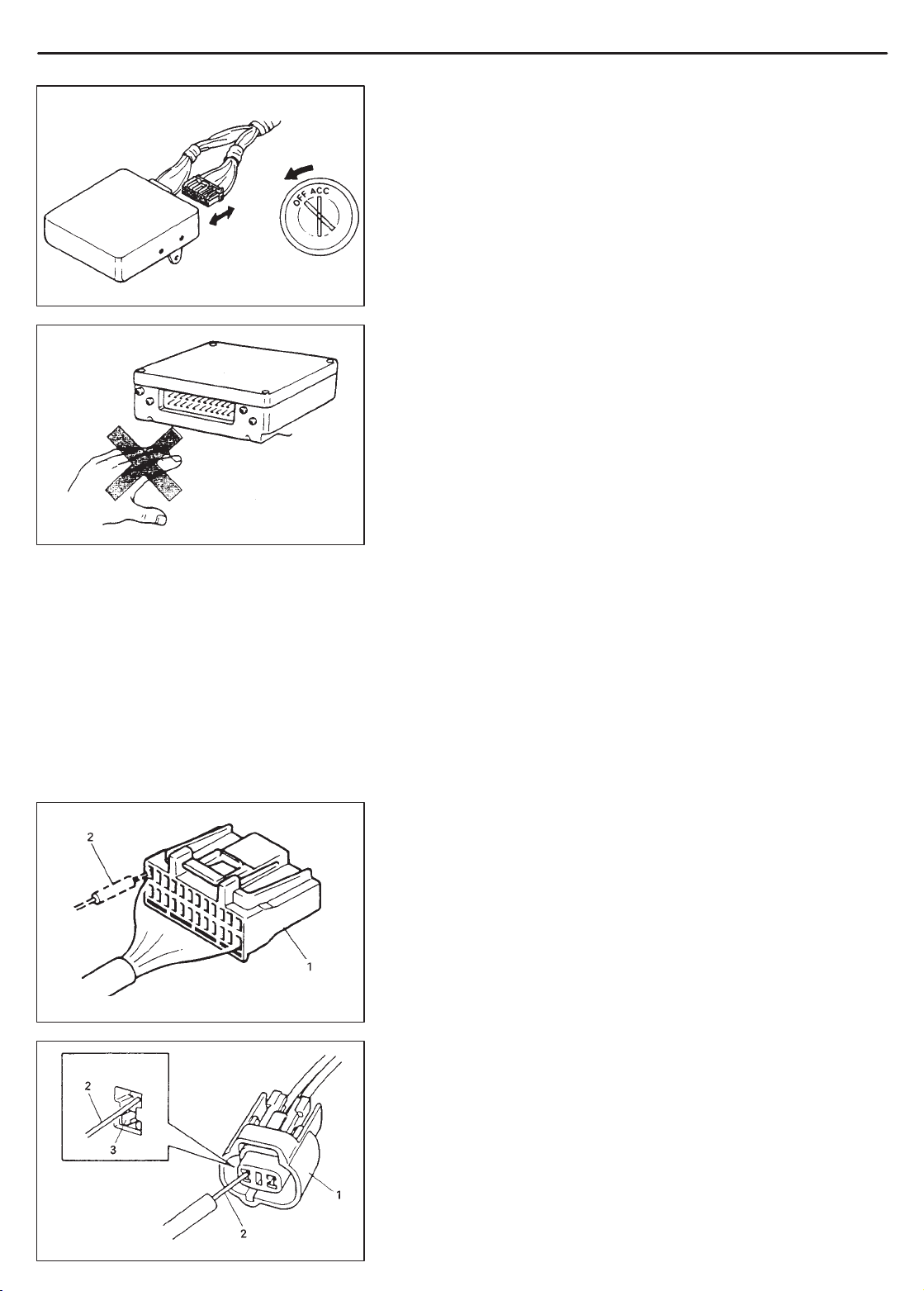
When disconnecting and connecting coupler, make sure to
turn ignition switch OFF, or electronic parts may get damaged.
Be careful not to touch the electrical terminals of parts which
use microcomputers (e.g. electronic control unit like as
ECM, PCM, P/S controller, etc.). The static electricity from
your body can damage these parts.
1. Coupler
2. Probe
3. Where male
terminal fits
1. Coupler
2. Probe
Never connect any tester (voltmeter, ohmmeter , or whatever)
to electronic control unit when its coupler is disconnected.
Attempt to do it may cause damage to it.
Never connect an ohmmeter to electronic control unit with
its coupler connected to it. Attempt to do it may cause damage to electronic control unit and sensors.
Be sure to use a specified voltmeter/ohmmeter. Otherwise,
accurate measurements may not be obtained or personal injury may result.
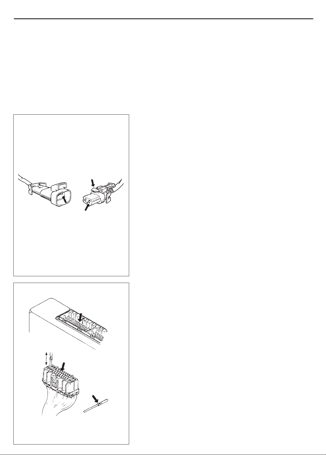
When taking measurements at electrical connectors using a
tester probe, be sure to insert the probe from the wire harness side (backside) of the connector.
When connecting meter probe from terminal side of coupler
because it can’t be connected from harness side, use extra
care not to bend male terminal of coupler of force its female
terminal open for connection.
In case of such coupler as shown connect probe as shown
to avoid opening female terminal.
Never connect probe where male terminal is supposed to fit.
GENERAL INFORMATION 0A-11
When checking connection of terminals, check its male half
for bend and female half for excessive opening and both for
locking (looseness), corrosion, dust, etc.
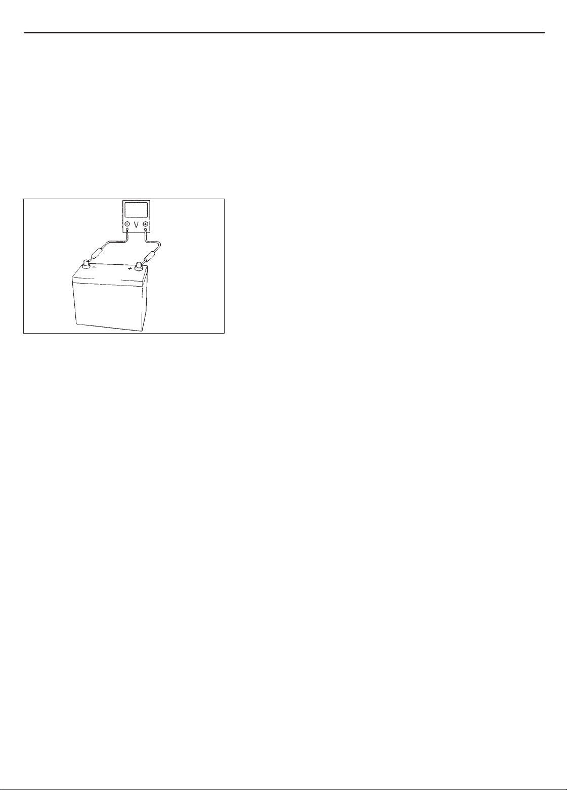
Before measuring voltage at each terminal, check to make
sure that battery voltage is 11V or higher . Such terminal voltage check at low battery voltage will lead to erroneous diagnosis.
0A-12 GENERAL INFORMATION
ELECTRICAL CIRCUIT INSPECTION
PROCEDURE
While there are various electrical circuit inspection methods, described here is a general method to check its open and short circuit
by using an ohmmeter and a voltmeter.
OPEN CIRCUIT CHECK
Possible causes for the open circuit are as follows. As the cause is
in the connector or terminal in many cases, they need to be checked
particularly carefully.
Loose connection of connector
Poor contact of terminal (due to dirt, corrosion or rust on it, poor
contact tension, entry of foreign object etc.)
Wire harness being open
Sensor
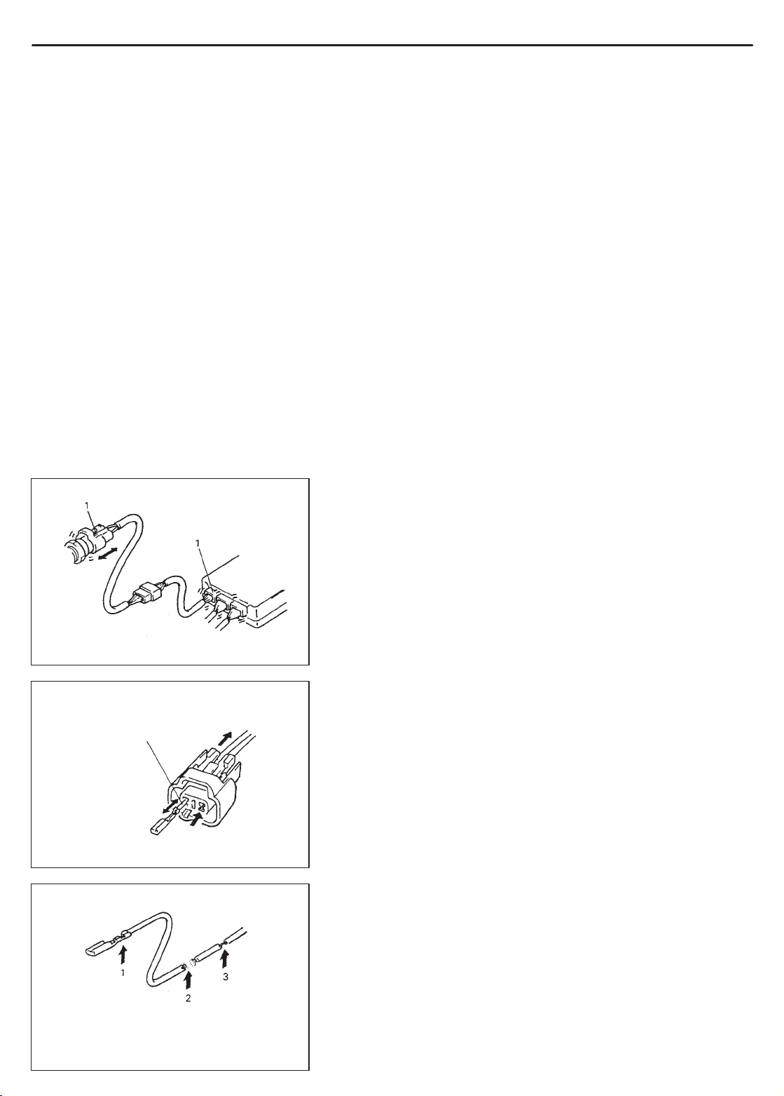
1. Check for loose connection
Check contact tension by
Inserting and removing just for
once
ECM
When checking system circuits including an electronic control unit
such as ECM, TCM, ABS control module, etc., it is important to perform careful check, starting with items which are easier to check.
1) Disconnect negative cable from battery.
2) Check each connector at both ends of the circuit being checked
for loose connection. Also check lock condition of connector if
equipped with connector lock.
3) Using a test male terminal, check both terminals of the circuit being checked for contact tension of its female terminal.
Check each terminal visually for poor contact (possibly caused
by dirt, corrosion, rust entry of foreign object, etc.).
At the same time, check to make sure that each terminal is
locked in the connector fully.
4) Using continuity check or voltage check procedure described in
the following page, check the wire harness for open circuit and
poor connection with its terminals. Locate abnormality, if any.
1. Looseness of crimping
2. Open
3. Thin wire (Single strand of wire)
GENERAL INFORMATION 0A-13
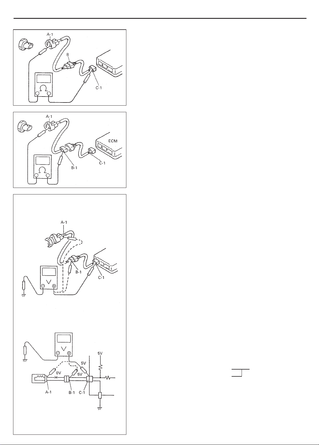
Continuity Check
1) Measure resistance between connector terminals at both ends
of the circuit being checked (between A-1 and C-1 in the figure).
If no continuity is indicated (infinity or over limit), that means that
the circuit is open between terminals A-1 and C-1.
2) Disconnect the connector included in the circuit (connector-B in
the figure) and measure resistance between terminals A-1 and
B-1.
If no continuity is indicated, that means that the circuit is open
between terminals A-1 and B-1. If continuity is indicated, there
is an open circuit between terminals B-1 and C-1 or an abnormality in connector-B.
Voltage Check
If voltage is supplied to the circuit being checked, voltage check can
be used as circuit check.
1) With all connectors connected and voltage applied to the circuit
being checked, measure voltage between each terminal and
body ground.
If measurements were taken as shown in the figure at the left
and results were as listed below, it means that the circuit is open
between terminals B-1 and A-1.
Voltage Between:
C-1 and body ground: Approx. 5V
B-1 and body ground: Approx. 5V
A-1 and body ground: 0V
Also, if measured values were as listed below, it means that
there is a resistance (abnormality) of such level that corresponds to the voltage drop in the circuit between terminals A-1
and B-1.
Voltage Between:
C-1 and body ground: Approx. 5V
B-1 and body ground: Approx. 5V
2V voltage drop
A-1 and body ground: Approx. 3V
0A-14 GENERAL INFORMATION
T o other
parts
Other parts
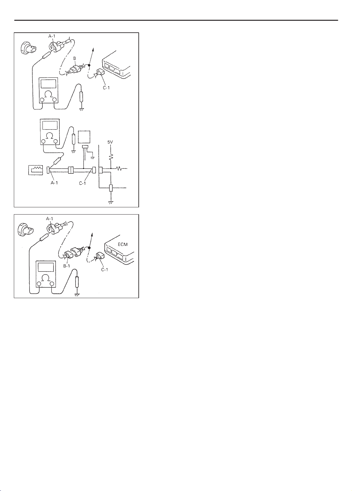
SHORT CIRCUIT CHECK (Wire harness to ground)
1) Disconnect negative cable from battery.
2) Disconnect connectors at both ends of the circuit to be checked.
NOTE:
If the circuit to be checked is connected to other parts, disconnect all connectors of those parts.
Otherwise, diagnosis will be misled.
3) Measure resistance between terminal at one end of circuit (A-1
terminal in figure) and body ground. If continuity is indicated, it
means that there is a short to ground between terminals A-1 and
C-1 of the circuit.
T o other
parts
4) Disconnect the connector included in circuit (connector B) and
measure resistance between A-1 and body ground.
If continuity is indicated, it means that the circuit is shorted to the
ground between terminals A-1 and B-1.
GENERAL INFORMATION 0A-15
INTERMITTENT AND POOR CONNECTION
Most intermittent are caused by faulty electrical connections or wiring, although a sticking relay or solenoid can occasionally be at
fault. When checking it for proper connection, perform careful
check of suspect circuits for:
Poor mating of connector halves, or terminals not fully seated in
the connector body (backed out).
Dirt or corrosion on the terminals. The terminals must be clean
and free of any foreign material which could impede proper terminal contact.
However, cleaning the terminal with a sand paper or the like is
prohibited.
Damaged connector body, exposing the terminals to moisture
and dirt, as well as not maintaining proper terminal orientation
with the component or mating connector.
1. Check contact tension by inserting and removing
just once.
2. Check each terminal for bend and proper alignment.
Improperly formed or damaged terminals.
Check each connector terminal in problem circuits carefully to ensure good contact tension by using the corresponding mating terminal.
If contact tension is not enough, reform it to increase contact tension or replace.
0A-16 GENERAL INFORMATION
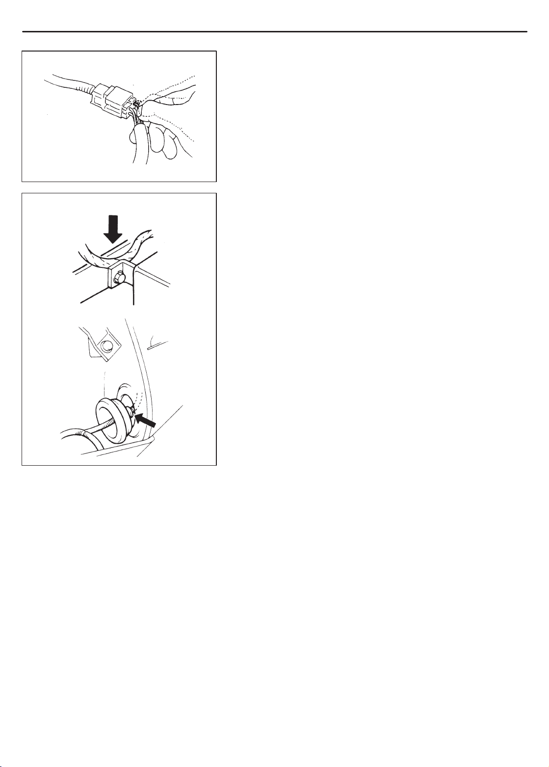
Poor terminal-to-wire connection.
Check each wire harness in problem circuits for poor connection
by shaking it by hand lightly. If any abnormal condition is found,
repair or replace.
Wire insulation which is rubbed through, causing an intermittent
short as the bare area touches other wiring or parts of the vehicle.
Wiring broken inside the insulation. This condition could cause
continuity check to show a good circuit, but if only 1 or 2 strands
of a multi-strand-type wire are intact, resistance could be far too
high.
If any abnormality is found, repair or replace.
PRECAUTION FOR INSTALLING MOBILE
COMMUNICATION EQUIPMENT
When installing mobile communication equipment such as CB (Citizens-Band)-radio or cellular-telephone, be sure to observe the following precautions.
Failure to follow cautions may adversely affect electronic control
system.
Keep the antenna as far away as possible from the vehicle’s elec-
tronic control unit.
Keep the antenna feeder more than 20 cm (7.9 in.) away from
electronic control unit and its wire harnesses.
Do not run the antenna feeder parallel with other wire harnesses.
Confirm that the antenna and feeder are correctly adjusted.
GENERAL INFORMATION 0A-17
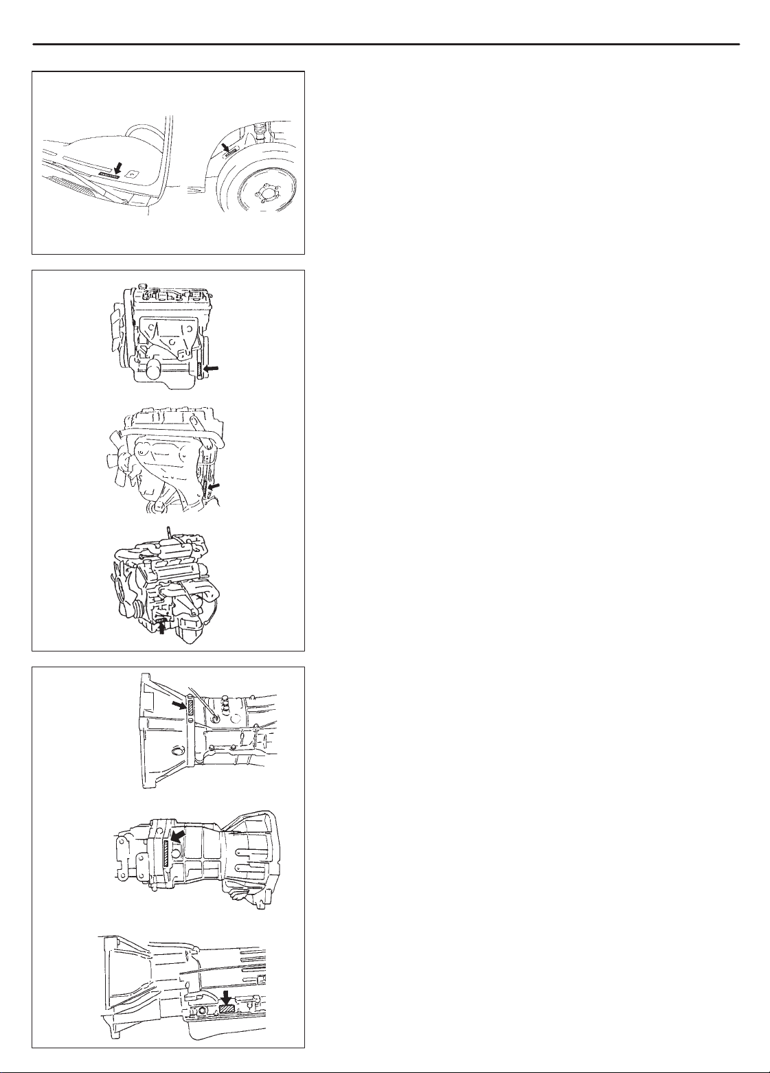
IDENTIFICATION INFORMATION
BODY NUMBER
The vehicle body number is on the left side of instrument panel and
punched on the chassis inside the tire housing on the right front side.
It is possible to identify the country of origin (the production plant)
of the vehicle by the first three digits of the body number as shown
below.
JSAxxx Japan (Iwata) produced. . . . . . . . . . .
2S2xxx Canada (CAMI) produced. . . . . . . . . . .
G16 engine
J20 engine
H25 engine
M/T (Type1)
ENGINE IDENTIFICATION NUMBER
The number is punched on the cylinder block.
TRANSMISSION IDENTIFICATION NUMBER
M/T (Type2)
4-speed A/T
The number is located on the transmission case.
0A-18 GENERAL INFORMATION
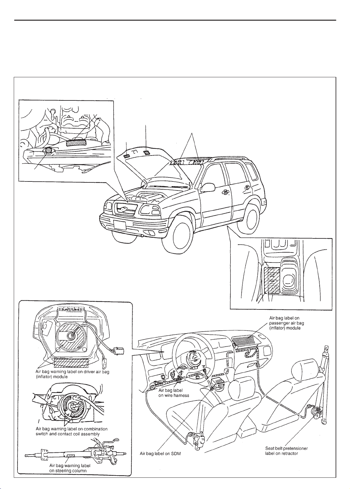
WARNING, CAUTION AND INFORMATION LABELS
The figure below shows main labels among others that are attached to vehicle component parts.
When servicing and handling parts, refer to WARNING/CAUTION instructions printed on labels.
If any WARNING/CAUTION label is found stained or damaged, clean or replace it as necessary.
NOTE:
Air bag CAUTION/WARNING labels are attached on
the vehicle equipped with air bag system only .
Engine cooling
Radiator cap
label
fan label
Emission control label
(Australia only)
Air bag label
Air bag label
on sun visor
Transfer label
GENERAL INFORMATION 0A-19
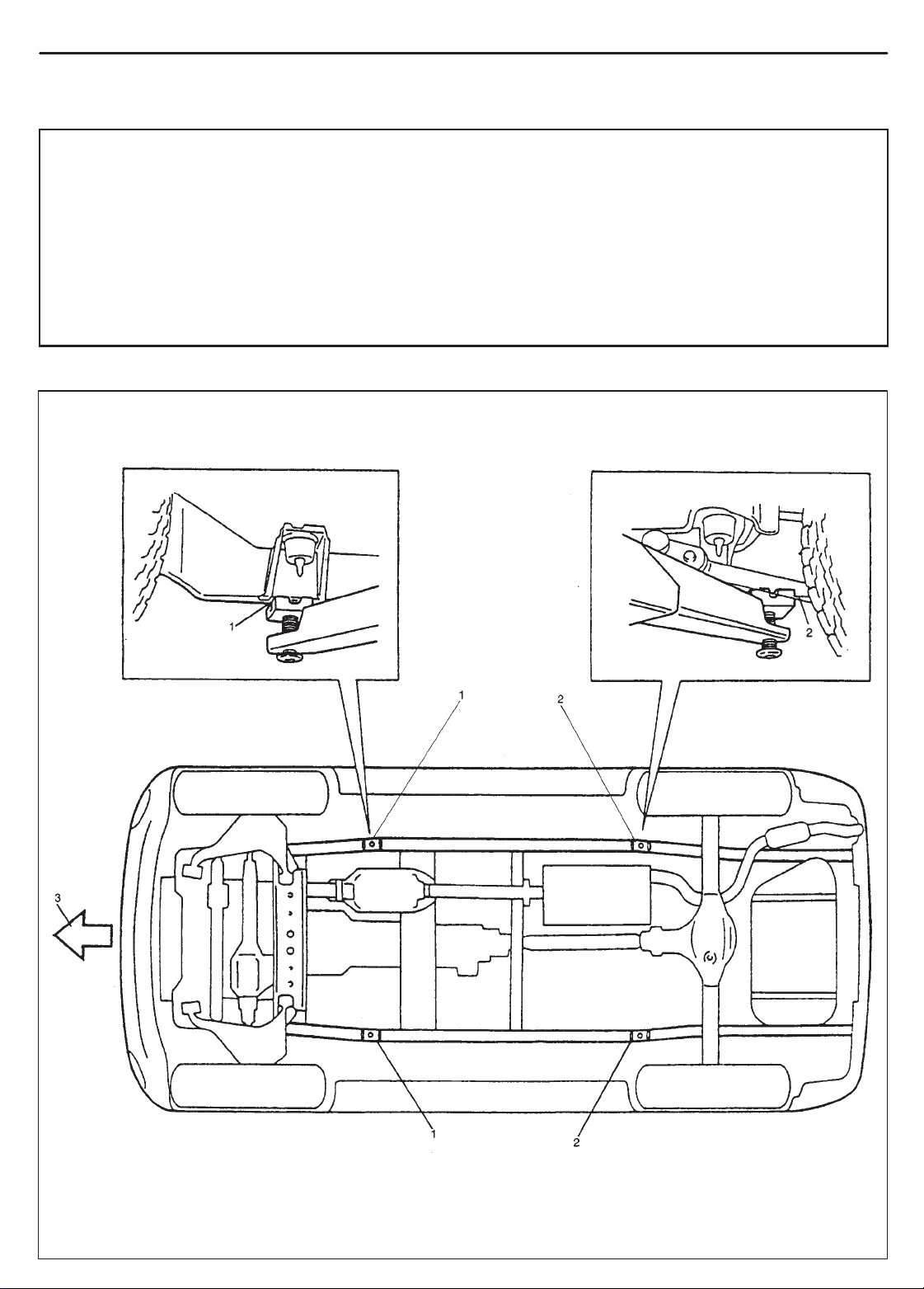
VEHICLE LIFTING POINTS
WARNING
When using frame contact hoist, apply hoist as shown (right and left at the same position). Lift up the
vehicle till 4 tires are a little off the ground and make sure that the vehicle will not fall off by trying to
move vehicle body in both ways. Work can be started only after this confirmation.
Before applying hoist to underbody, always take vehicle balance throughout service into consider-
ation. Vehicle balance on hoist may change depending of what part to be removed.
Make absolutely sure to lock hoist after vehicle is hoisted up.
Before lifting up the vehicle, check to be sure that end of hoist arm is not in contact with brake pipe,
fuel pipe, bracket or any other part.
When using frame contact hoist:
1. Front lifting point
2. Rear lifting point
3. Front
0A-20 GENERAL INFORMATION
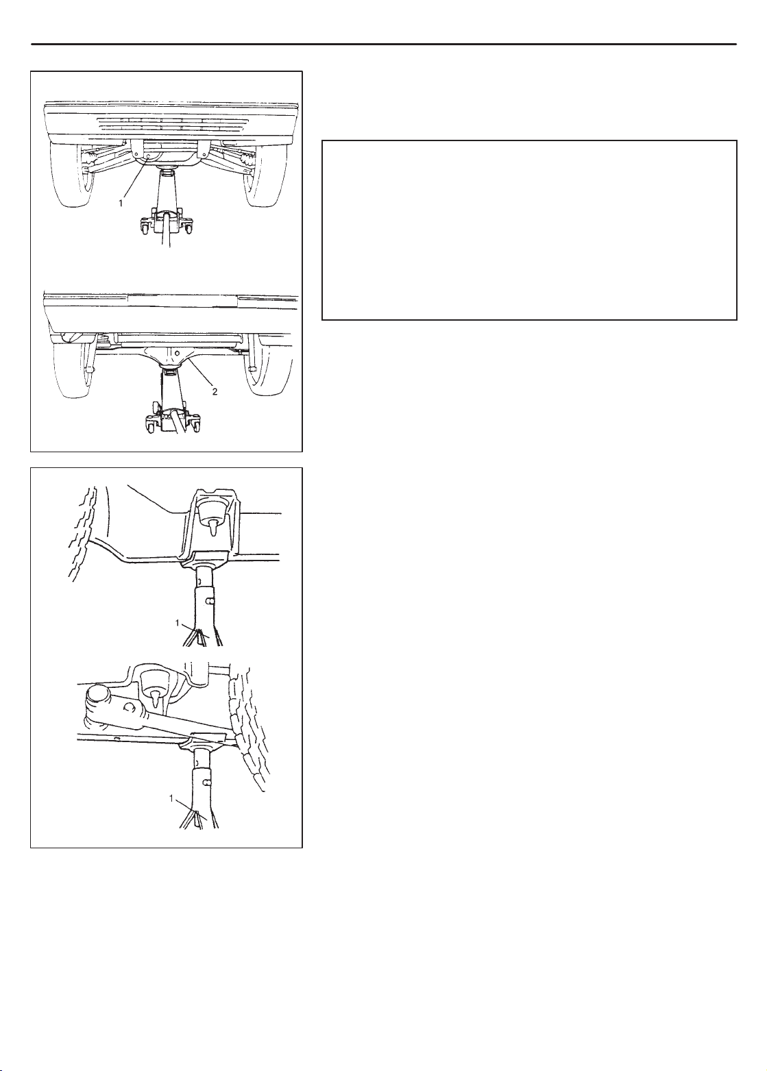
When using floor jack:
Front
1. Front differential housing
2. Rear axle
housing
In raising front or rear vehicle end off the floor by jacking, be sure
to put the jack against the center portion of the front suspension
frame or rear axle housing.
WARNING:
Never apply jack against suspension parts (i.e., stabilizer,
etc.) or vehicle floor, or it may get deformed.
If the vehicle to be jacked up only at the front or rear end,
be sure to block the wheels on ground in order to ensure
safety .
After the vehicle is jacked up, be sure to support it on
stands. It is extremely dangerous to do any work on the
vehicle raised on jack alone.
To perform service with either front or rear vehicle end jacked up,
be sure to place safety stands under chassis frame so that body is
securely supported. And then check to ensure that chassis frame
does not slide on safety stands and the vehicle is held stable for
safety’s sake.
Rear
1. Safety stands

GENERAL INFORMATION 0A-21
ABBREVIATIONS MAY BE USED IN THIS MANUAL
A
ABS : Anti-lock Brake System
ATDC : After Top Dead Center
API : American Petroleum Institute
ATF : Automatic Transmission Fluid
ALR : Automatic Locking Retractor
AC : Alternating Current
A/T : Automatic Transmission
A/C : Air Conditioning
ABDC : After Bottom Dead Center
A/F : Air Fuel Mixture Ratio
A-ELR : Automatic-Emergency
Locking Retractor
B
B+ : Battery Positive Voltage
BTDC : Before Top Dead Center
BBDC : Before Bottom Dead Center
C
CKT : Circuit
CMP Sensor : Camshaft Position Sensor
(Crank Angle Sensor, CAS)
CO : Carbon Monoxide
CPP Switch : Clutch Pedal Position Switch
(Clutch Switch, Clutch Start
Switch)
CPU : Central Processing Unit
CRS : Child Restraint System
D
DC : Direct Current
DLC : Data Link Connector
(Assembly Line Diag. Link,
ALDL, Serial Data Link, SDL)
DOHC : Double Over Head Camshaft
DOJ : Double Offset Joint
DRL : Daytime Running Light
DTC : Diagnostic Trouble Code
(Diagnostic Code)
E
EBCM : Electronic Brake Control
Module, ABS Control
Module
EBD : Electric Brake force Distribution
ECM : Engine Control Module
ECT Sensor : Engine Coolant Temperature
Sensor (Water Temp.
Sensor, WTS)
EGR : Exhaust Gas Recirculation
EGRT Sensor : EGR Temperature Sensor
(Recirculated Exhaust Gas
Temp. Sensor, REGTS)
EFE Heater : Early Fuel Evaporation
Heater (Positive Temperature
Coefficient, PTC Heater)
ELR : Emergency Locking Retractor
EPS : Electronic Power Steering
EVAP : Evaporative Emission
EVAP Canister : Evaporative Emission
Canister (Charcoal Canister)
F
4WD : 4 Wheel Drive
G
GEN : Generator
GND : Ground
H
HC : Hydrocarbons
HO2S : Heated Oxygen Sensor
I
IAC Valve : Idle Air Control Valve (Idle
Speed Control Solenoid
Valve, ISC Solenoid Valve)
IAT Sensor : Intake Air Temperature
Sensor (Air temperature
Sensor, ATS)
ICM : Immobilizer Control Module
IG : Ignition
ISC Actuator : Idle Speed Control Actuator
(Motor)

0A-22 GENERAL INFORMATION
L
LH : Left Hand
LSPV : Load Sensing Proportioning
Valve
M
MAF Sensor : Mass Air Flow Sensor
(Air Flow Sensor, AFS, Air
Flow Meter, AFM)
MAP Sensor : Manifold Absolute Pressure
Sensor (Pressure Sensor, PS)
Max : Maximum
MFI : Multiport Fuel Injection
(Multipoint Fuel Injection)
Min : Minimum
MIL : Malfunction Indicator Lamp
(“CHECK ENGINE” Light)
M/T : Manual Transmission
N
NOx : Nitrogen Oxides
O
OBD : On-Board Diagnostic System
(Self-Diagnosis Function)
O/D : Overdrive
OHC : Over Head Camshaft
P
PNP : Park/Neutral Position
P/S : Power Steering
PSP Switch : Power Steering Pressure
Switch (P/S Pressure Switch)
PCM : Powertrain Control Module
PCV : Positive Crankcase Ventilation
T
TBI : Throttle Body Fuel Injection
(Single-Point Fuel Injection,
SPI)
TCC : Torque Converter Clutch
TCM : Transmission Control Module
(A/T Controller, A/T Control
Module)
TP Sensor : Throttle Position Sensor
TVV : Thermal Vacuum Valve
(Thermal Vacuum Switching
Valve, TVSV, Bimetal Vacuum
Switching Valve, BVSV)
TWC : Three Way Catalytic
Converter (Three Way
Catalyst)
2WD : 2 Wheel Drive
V
VIN : Vehicle Identification
Number
VSS : Vehicle Speed Sensor
W
WU-OC : Warm Up Oxidation
Catalytic Converter
WU-TWC : Warm Up Three Way
Catalytic Converter
R
RH : Right Hand
S
SAE : Society of Automotive
Engineers
SDM : Sensing and Diagnostic
Module (Air bag controller,
Air bag control module)
SFI : Sequential Multiport Fuel
Injection
SOHC : Single Over Head Camshaft
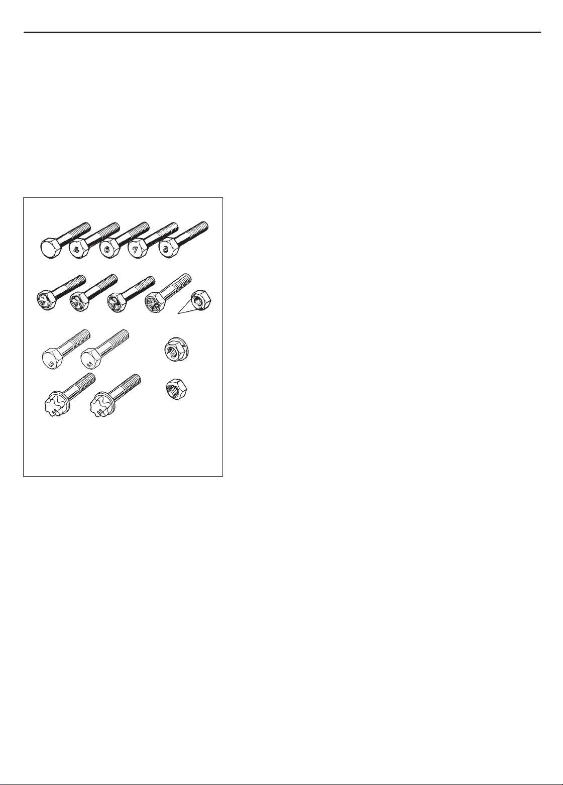
NUT STRENGTH
IDENTIFICA TION
GENERAL INFORMATION 0A-23
METRIC INFORMATION
METRIC FASTENERS
Most of the fasteners used for this vehicle are metric fasteners.
When replacing any fasteners, it is most important that replacement
fasteners be the correct diameter, thread pitch and strength.
FASTENER STRENGTH IDENTIFICATION
Most commonly used metric fastener strength property classes are
4T , 6.8, 7T , 8.8 and radial line with the class identification embossed
on the head of each bolt. Some metric nuts will be marked with
punch, 6 or 8 mark strength identification on the nut face. Figure
shows the different strength markings.
When replacing metric fasteners, be careful to use bolts and nuts
of the same strength or greater than the original fasteners (the
same number marking or higher). It is likewise important to select
replacement fasteners of the correct diameter and thread pitch.
Correct replacement bolts and nuts are available through the parts
division.
METRIC BOLTS–IDENTIFICATION CLASS NUMBERS
OR MARKS CORRESPOND TO BOLT
STRENGTH–INCREASING NUMBERS REPRESENT
INCREASING STRENGTH.
0A-24 GENERAL INFORMATION
45681012141618
g
g
g
g
g
g
g
g
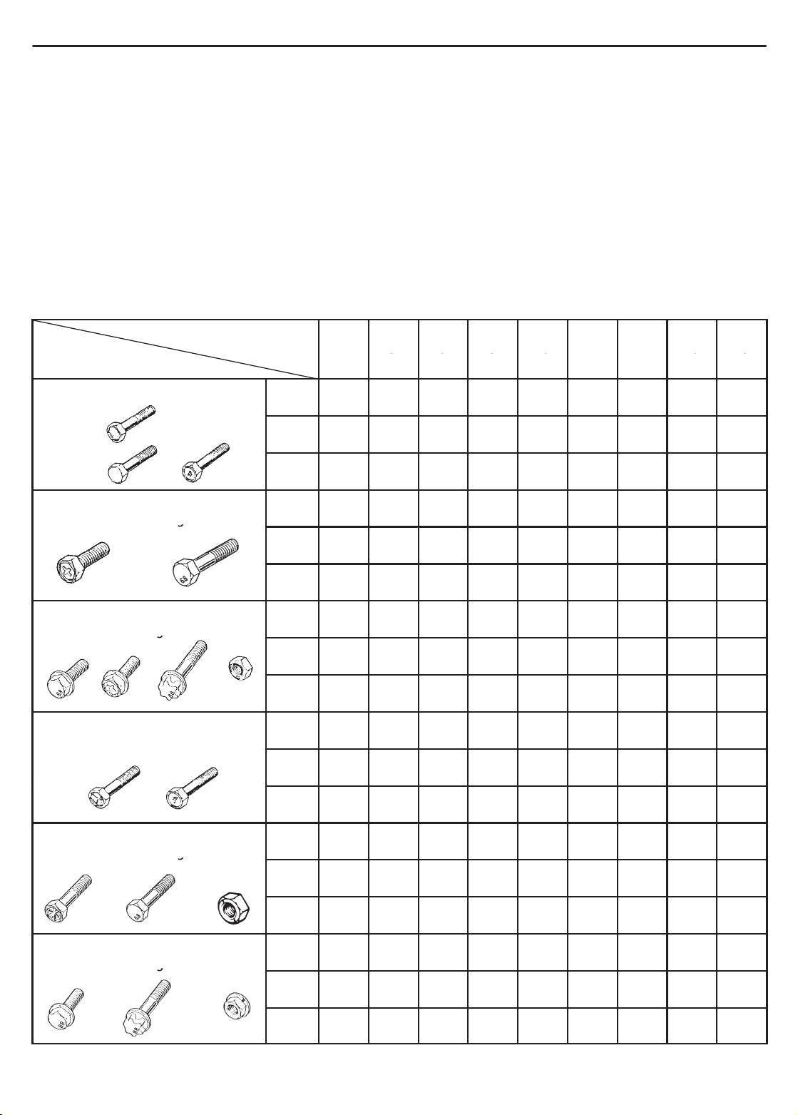
STANDARD TIGHTENING TORQUE
Each fastener should be tightened to the torque specified in each section of this manual. If no description or specification is provided, refer to the following tightening torque chart for the applicable torque for each fastener. When
a fastener of greater strength than the original one is used, however, use the torque specified for the original fastener.
NOTE:
For the flanged bolt, flanged nut and self-lock nut of 4T and 7T strength, add 10% to the tightening torque
given in the chart below.
The chart below is applicable only where the fastened parts are made of steel or light alloy.
Tightening torque chart
Thread Diameter (Nominal Diameter)
(mm)
Strength
4 5 6 8 10 12 14 16 18
A equivalent of 4T strength
fastener
A equivalent of 6.8 strength
fastener without flan
e
A equivalent of 6.8 strength
fastener with flan
e
A equivalent of 7T strength
fastener
Self-lock
nut
N.m 1.5 3.0 5.5 13 29 45 65 105 160
kg-m 0.15 0.30 0.55 1.3 2.9 4.5 6.5 10.5 16
lb-ft 1.0 2.5 4.0 9.5 21.0 32.5 47.0 76.0 116.0
N.m 2.4 4.7 8.4 20 42 80 125 193 280
kg-m 0.24 0.47 0.84 2.0 4.2 8.0 12.5 19.3 28
lb-ft 2.0 3.5 6.0 14.5 30.5 58.0 90.5 139.5 202.5
N.m 2.4 4.9 8.8 21 44 84 133 203 298
kg-m 0.24 0.49 0.88 2.1 4.4 8.4 13.3 20.3 29.8
lb-ft 2.0 3.5 6.5 15.5 32.0 61.0 96.5 147.0 215.5
N.m 2.3 4.5 10 23 50 85 135 210 240
kg-m 0.23 0.45 1.0 2.3 5.0 8.5 13.5 21 24
lb-ft 2.0 3.5 7.5 17.0 36.5 61.5 98.0 152.0 174.0
A equivalent of 8.8 strength
fastener without flan
A equivalent of 8.8 strength
fastener with flan
e
e
N.m 3.1 6.3 11 27 56 105 168 258 373
kg-m 0.31 0.63 1.1 2.7 5.6 10.5 16.8 25.8 37.3
lb-ft 2.5 4.5 8.0 19.5 40.5 76.0 121.5 187.0 270.0
N.m 3.2 6.5 12 29 59 113 175 270 395
kg-m 0.32 0.65 1.2 2.9 5.9 11.3 17.5 27 39.5
lb-ft 2.5 5.0 9.0 21.0 43.0 82.0 126.5 195.5 286.0

MAINTENANCE AND LUBRICATION 0B-1
SECTION 0B
MAINTENANCE AND LUBRICATION
WARNING:
For vehicles equipped with Supplemental Restraint (Air Bag) System:
Service on and around the air bag system components or wiring must be performed only by an autho-
rized SUZUKI dealer. Refer to “Air Bag System Components and W iring Location View” under “General Description” in air bag system section in order to confirm whether you are performing service on
or near the air bag system components or wiring. Please observe all WARNINGS and “Service Precautions” under “On-Vehicle Service” in air bag system section before performing service on or around
the air bag system components or wiring. Failure to follow WARNINGS could result in unintentional
activation of the system or could render the system inoperative. Either of these two conditions may
result in severe injury.
T echnical service work must be started at least 90 seconds after the ignition switch is turned to the
“LOCK” position and the negative cable is disconnected from the battery . Otherwise, the system may
be activated by reserve energy in the Sensing and Diagnostic Module (SDM).
0B
CONTENTS
MAINTENANCE SCHEDULE 0B- 2. . . . . . . . . . . . . . . . . . . . . . . . . . . . . . . . . . . . . . . . . . . . . . . . . . . . . . . . . . . . . . . .
Maintenance Schedule Under Normal Driving Conditions 0B- 2. . . . . . . . . . . . . . . . . . . . . . . . . . . . . . . . . . . . . .
Maintenance Recommended Under Severe Driving Conditions 0B- 4. . . . . . . . . . . . . . . . . . . . . . . . . . . . . . . . .
MAINTENANCE SERVICE 0B- 5. . . . . . . . . . . . . . . . . . . . . . . . . . . . . . . . . . . . . . . . . . . . . . . . . . . . . . . . . . . . . . . . . .
Engine 0B- 5. . . . . . . . . . . . . . . . . . . . . . . . . . . . . . . . . . . . . . . . . . . . . . . . . . . . . . . . . . . . . . . . . . . . . . . . . . . . . . . . . .
Ignition System 0B-12. . . . . . . . . . . . . . . . . . . . . . . . . . . . . . . . . . . . . . . . . . . . . . . . . . . . . . . . . . . . . . . . . . . . . . . . . . .
Fuel System 0B-12. . . . . . . . . . . . . . . . . . . . . . . . . . . . . . . . . . . . . . . . . . . . . . . . . . . . . . . . . . . . . . . . . . . . . . . . . . . . .
Emission Control System 0B-14. . . . . . . . . . . . . . . . . . . . . . . . . . . . . . . . . . . . . . . . . . . . . . . . . . . . . . . . . . . . . . . . . .
Chassis and Body 0B-15. . . . . . . . . . . . . . . . . . . . . . . . . . . . . . . . . . . . . . . . . . . . . . . . . . . . . . . . . . . . . . . . . . . . . . . .
Final Inspection 0B-24. . . . . . . . . . . . . . . . . . . . . . . . . . . . . . . . . . . . . . . . . . . . . . . . . . . . . . . . . . . . . . . . . . . . . . . . . .
RECOMMENDED FLUIDS AND LUBRICANTS 0B-25. . . . . . . . . . . . . . . . . . . . . . . . . . . . . . . . . . . . . . . . . . . . . . . .
0B-2 MAINTENANCE AND LUBRICATION
This interval should be judged by
g
unleaded
fuel is
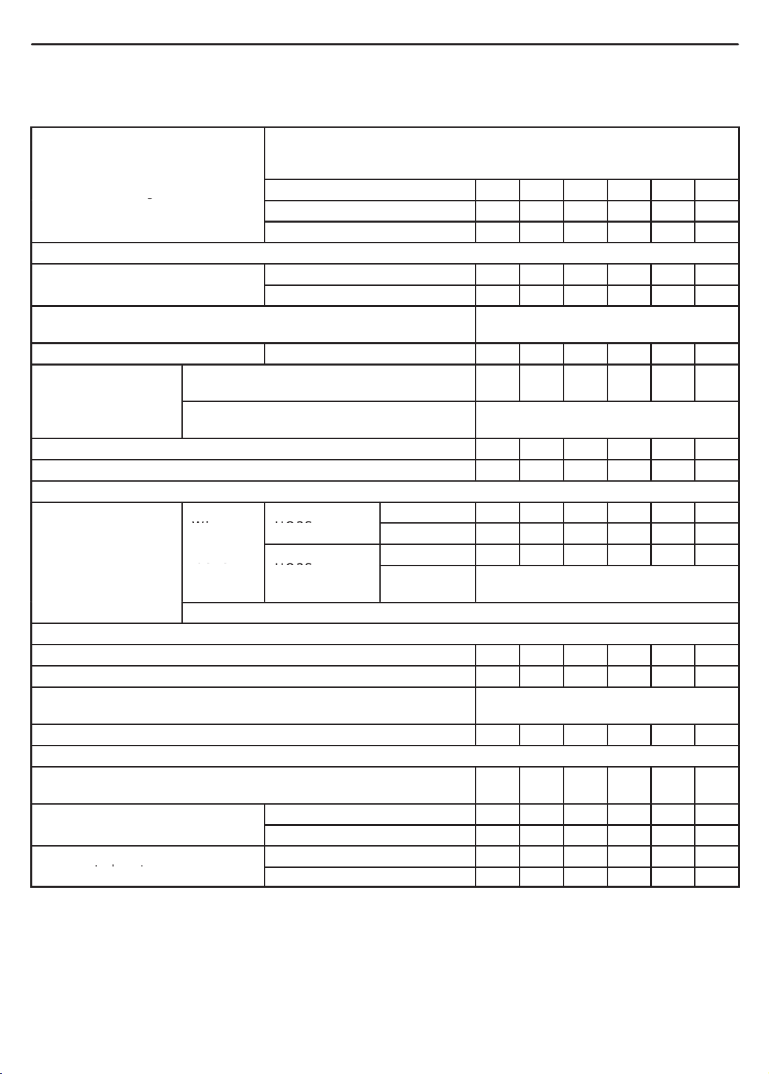
MAINTENANCE SCHEDULE
MAINTENANCE SCHEDULE UNDER NORMAL DRIVING CONDITIONS
This table includes services as scheduled up to 90,000 km
Interval:
odometer reading or months,
whichever comes first.
ENGINE
1-1. Drive belt
1-2. Camshaft timing belt (G16 engine only) Replace every 100,000 km or
1-3. Valve lash (clearance) G16 engine only – I – I – I
1-4. Engine oil and
oil filter
1-5. Engine coolant – – R – – R
1-6. Exhaust system – I – I – I
IGNITION SYSTEM
2-1. Spark plugs
FUEL SYSTEM
3-1. Air cleaner filter I I R I I R
3-2. Fuel lines and connections – I – I – I
3-3. Fuel filter Replace every 105,000 km or 63,000
3-4. Fuel tank – – I – – I
EMISSION CONTROL SYSTEM
4-1. Crankcase ventilation hoses and connections
(Vehicle without HO2S)
4-2. PCV valve
4-3. Fuel evaporative emission
control system
J20/H25 engines
G16 engine with HO2S (SG, SH, SJ)
G16 engine with HO2S (SE, SF),
G16 engine without HO2S
When
fuel is
used
When leaded fuel is used, refer to “Severe Driving Condition” schedule
(54,000 miles) mileage. Beyond 90,000 km (54,000 miles), carry
out the same services at the same intervals respectively.
Km (x 1,000) 15 30 45 60 75 90
Miles (x 1,000) 9 18 27 36 45 54
Months 12 24 36 48 60 72
V-belt I R I R I R
V-rib belt (Flat type) – – I – – R
60,000 miles
R R R R R R
Replace every 10,000 km (6,000 miles)
or 8 months
Vehicle without
HO2S
Vehicle with
HO2S
Vehicle without HO2S – – I – – I
Vehicle with HO2S – – – – – I
Vehicle without HO2S – I – I – I
Vehicle with HO2S – – – – – I
Nickel plug – R – R – R
Iridium plug – – – R – –
Nickel plug – – R – – R
Iridium plug Replace every 105,000 km or 63,000
miles
miles
– – I – – I
NOTES:
“R”: Replace or change
“I” : Inspect and correct, replace or lubricate if necessary
For Item 1-2. Camshaft timing belt: This belt may be replaced every 90,000 km (54,000 miles) according
to customer’s maintenance convenience.
For Sweden, item 2-1, 4-2 and 4-3 should be performed by odometer reading only.
For Item 2-1. Spark plugs, replace every 50,000 km if the local law requires.
Nickel spark plug: BKR6E-11 or K20PR-U11
Iridium spark plug: IFR6E1 1 or SK20PR-A11 for G16 engine, IFR5J11 or SK16PR11 for J20/H25 engines
 Loading...