

Page 1

suzuki :: Suzuki Truck Vitara JS (4Dr) 2WD L4-
2.0L (2000)
Page 2

> Relays and Modules > Relays and Modules - Accessories and Optional Equipment > Keyless Entry Module > Component Information > Locations
Page 3

Instrument Panel
Page 4

> Relays and Modules > Relays and Modules - Accessories and Optional Equipment > Keyless Entry Module > Component Information > Diagrams > Diagram Information and Instructions
Keyless Entry Module: Diagram Information and Instructions
Page 5

> Relays and Modules > Relays and Modules - Accessories and Optional Equipment > Keyless Entry Module > Component Information > Diagrams > Diagram Information
and Instructions > Page 9
Vitara JS (4Dr) 2WD L4-2.0L (2000)
Body Electrical System
Page 6

The wire color is abbreviated to the first (or first two) alphabet(s) of each color.
There are two kinds of colored wire used in this vehicle. One is single-colored wire and the other is dual-colored (striped) wire. The single-colored wireuses only one color symbol (i.e. "G"). The dual-colored wire uses two color symbols (i.e. "G/Y"). The first symbol represents the base color of the wire("G" in the figure) and the second symbol represents the color of the stripe ("Y" in the figure).
How to Locate Ground Point
Page 7

> Relays and Modules > Relays and Modules - Accessories and Optional Equipment > Keyless Entry Module > Component Information > Diagrams > Diagram Information
and Instructions > Page 10
Vitara JS (4Dr) 2WD L4-2.0L (2000)
Page 8

Look in ("GROUND POINT") for the black circle with the same numerical figure as the one described ("SYSTEM CIRCUIT DIAGRAM").
If there is an electrical part whose ground point Is not found In ("GROUND POINT"), that part Itself serves as a ground.NOTE:
How to Read Connector Codes and Pin NOS.
Page 9

> Relays and Modules > Relays and Modules - Accessories and Optional Equipment > Keyless Entry Module > Component Information > Diagrams > Diagram Information
and Instructions > Page 11
Vitara JS (4Dr) 2WD L4-2.0L (2000)
Page 10

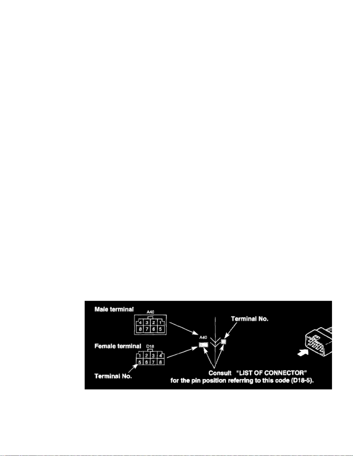
It is possible to retrieve the location and shape of each connector from the connector code indicated in ("SYSTEM CIRCUIT DIAGRAM") and theposition of each pin from the connector pin No.
To Retrieve Location of Connector:
Open ("SYSTEM CIRCUIT DIAGRAM") to consult the connector code of the questioned connector. Then, refer to ("CONNECTOR LAYOUTDIAGRAM") and look for the same code as the connector code in question. The place where the code is found is the location of that connector.
To Retrieve Shape or Pin No.:
Open ("SYSTEM CIRCUIT DIAGRAM") to consult the connector code and pin No. of the connector of interest. Then, refer to ("LIST OFCONNECTORS") as shown at the right in the figure and look for the desired connector code where the shape of that connector is shown. This method isconvenient when locating the connector of interest among similar connectors. Also, by using this information, it is possible to find the position of eachpin from the connector pin No. provided in ("SYSTEM CIRCUIT DIAGRAM"). It is helpful when retrieving pin position in the connector for checkingcontinuity between pins.
To know the location, shape or pin position of the connector, cross-refer ("SYSTEM CIRCUIT DIAGRAM"),("CONNECTOR LAYOUT DIAGRAM")and ("LIST OF CONNECTORS") as follows:
How to Read Connector Layout Diagram
Page 11

> Relays and Modules > Relays and Modules - Accessories and Optional Equipment > Keyless Entry Module > Component Information > Diagrams > Diagram Information
and Instructions > Page 12
Vitara JS (4Dr) 2WD L4-2.0L (2000)
Page 12

When necessary to know the location of an electrical part or intermediate connector, it is easily possible to retrieve it by this diagram.
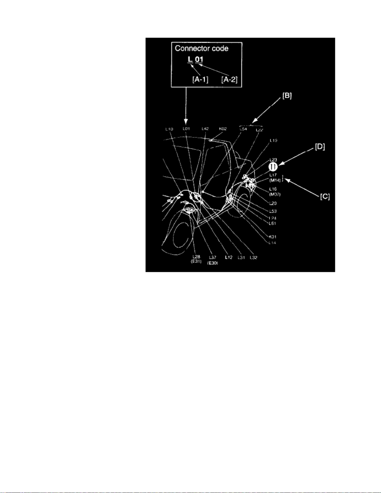
First consult ("SYSTEM CIRCUIT DIAGRAM") or connector table for the connector code of interest. Second refer to the diagrams and look for thesame code. More information on use of the code is illustrated below.
[A-1]:
Harness symbol and corresponding harness name
A: Battery cableB: A/C harnessC: Engine harnessD: Injector harnessE: Main harness
Oil pressure wire Console wire
G: Instrument panel harnessJ: Front and rear door harnessK: Roof wire
Spot light wire
L: Floor harnessO: Back door harness License light wire
High mounted stop light wire
Page 13

> Relays and Modules > Relays and Modules - Accessories and Optional Equipment > Keyless Entry Module > Component Information > Diagrams > Diagram Information
and Instructions > Page 13
Vitara JS (4Dr) 2WD L4-2.0L (2000)
Q: Air bag harnessR: Fuel pump harness
[A-2]:
Connector Number (Serial number: 01)
[B]:
This indicates the intermediate connector.Nos. are given to male and female connectors respectively. When the harness symbol (alphabet) is different, so is the harness name. (For the details, referto [A-1] above.)
Page 14

[C]:
This indicates the connector code.The connector code in the parentheses () has the same meaning as the above intermediate connector and at the same time, it indicates that there is aharness continuity ("CONNECTOR LAYOUT DIAGRAM"). That is, it suggests that the harness is continued to the other illustration and the continuedharness can be identified by the same connector code.
[D]:
This indicates the ground point No.The same No. is used as the ground point. (For the details, refer to ("GROUND POINT").)
How to Read Ground Point
Ground point means the position where the negative harness among wiring harnesses is grounded. The diagram in ("GROUND POINT") shows suchground points. In ("SYSTEM CIRCUIT DIAGRAM"), there are many ground marks followed by black circles with numerical figures in them whichmean that the end of the harness with such black circle is grounded to some part of the vehicle.
To locate the ground point (installation position), refer to ("GROUND POINT").
How to Read Power Supply Diagram
Page 15

> Relays and Modules > Relays and Modules - Accessories and Optional Equipment > Keyless Entry Module > Component Information > Diagrams > Diagram Information
and Instructions > Page 14
Vitara JS (4Dr) 2WD L4-2.0L (2000)
Page 16

Power supply diagram shows the circuit from the positive terminal of the battery to each fuse in the box and where each fuse is connected (each systemcircuit name). In addition, the electric load value of each fuse is indicated.
Since every ("SYSTEM CIRCUIT DIAGRAM") is drawn from the circuit down the fuse, cross-refer to ("POWER SUPPLY DIAGRAM") for thecontinuity of the upper circuit referring to fuse No. at each fuse symbol mark.
How to Read System Circuit Diagram
Page 17

> Relays and Modules > Relays and Modules - Accessories and Optional Equipment > Keyless Entry Module > Component Information > Diagrams > Diagram Information
and Instructions > Page 15
Vitara JS (4Dr) 2WD L4-2.0L (2000)
Page 18

The circuit diagram of each system shows the electric circuit from the main fuse, fuse box or the ignition switch (at the top in the diagram) to the ground(at the bottom) so that the circuit can be followed easily when performing inspection and service work.
Further information on connector, ground point and fuses is provided by cross-reference of "SYSTEM CIRCUIT DIAGRAM" and the other Systems asdescribed in the preceding indications.
Connector code, ground No. and fuse No. are the reference code for cross-reference.
[A]: Fuse No.
This No. indicates the reference code to power supply diagram. (Refer to ("POWER SUPPLY DIAGRAM") for the continuity of the upper circuit.)
[B]: Connector mark
This indicates that the connector is identical.
[C]:
Variations by specifications are identified by codes.
Page 19

> Relays and Modules > Relays and Modules - Accessories and Optional Equipment > Keyless Entry Module > Component Information > Diagrams > Diagram Information
and Instructions > Page 16
Vitara JS (4Dr) 2WD L4-2.0L (2000)
[D]:
This indicates continuity between the same symbols.
[E]: Wire color
This indicates the wire color. (Refer to "WIRE COLOR SYMBOLS".)
[F]:
This indicates the variations by the specifications.
Page 20
[G]:
This indicates that the circuit is continued to the same symbol.
[H]:
This indicates that the shield wire.
[I]: Ground point
This indicates the ground No. (Refer to ("GROUND POINT") for the location.)
[J]: Symbol mark
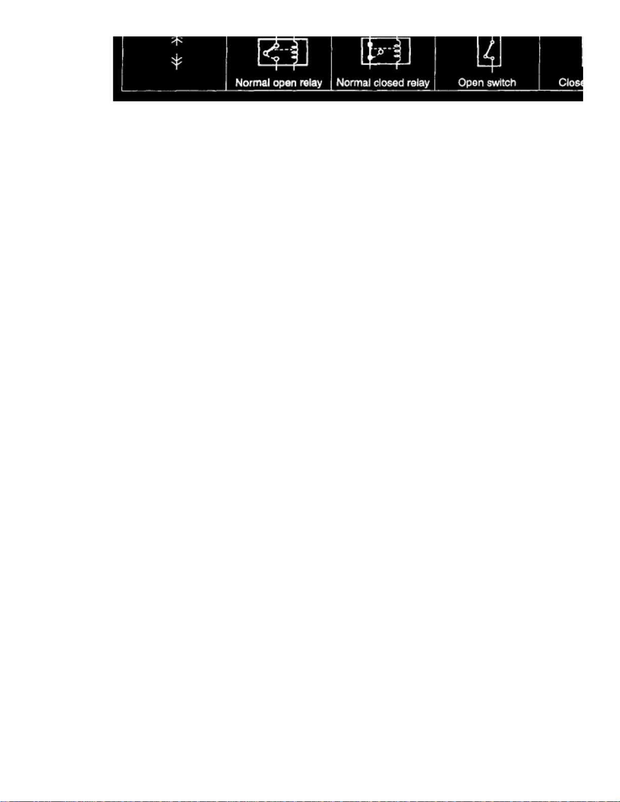
Symbol marks are used for better legibility. For more information, refer to "SYMBOLS AND MARKS".
[K]: Identical marks
This indicates that the intermediate connector is identical.
[L]:
This indicates variation of circuit depending on specifications.
[M]: Connector code
This indicates the reference code to ("CONNECTOR LAYOUT DIAGRAM") or ("LIST OF CONNECTORS") for further information.
[N]: Pin No.
This indicates the pin No. (Refer to ("LIST OF CONNECTORS") for the pin position in the connector.)
Indication of Connectors and How to Read Them
1.
- The male terminal and female terminal are identified by a double enclosure and a single one respectively.
-
Page 21
> Relays and Modules > Relays and Modules - Accessories and Optional Equipment > Keyless Entry Module > Component Information > Diagrams > Diagram Information
and Instructions > Page 17
Vitara JS (4Dr) 2WD L4-2.0L (2000)
The connectors are indicated as shown below in ("SYSTEM CIRCUIT DIAGRAM"). For the shape and pin arrangement of each connector used, referto ("LIST OF CONNECTORS"). Described below are how they are indicated and how to read them
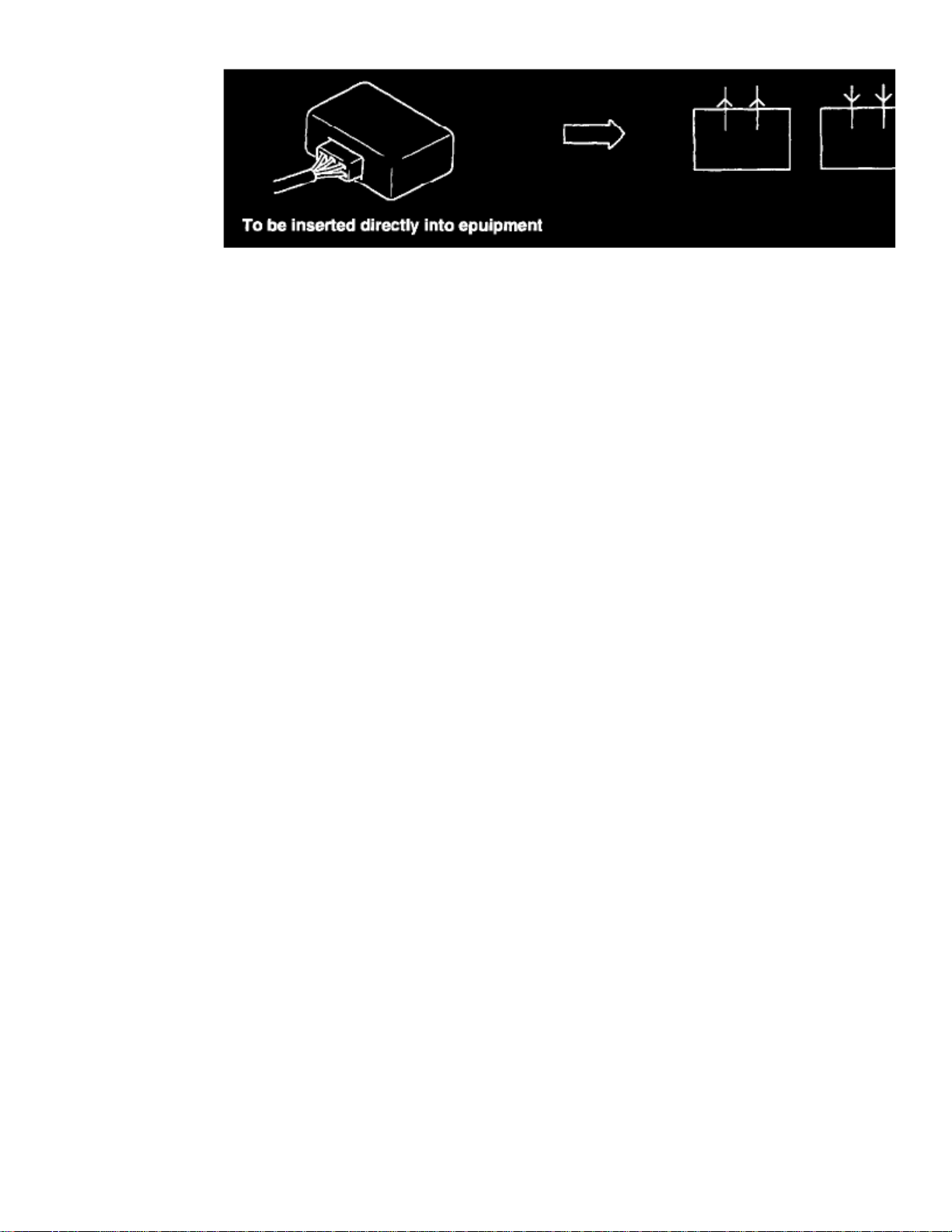
The intermediate connector which connects harnesses is shown by both shapes of the male terminal and the female terminal but the connector to beconnected directly to the equipment is shown by the shape of the connector on the harness side.- The connectors described are always "harness side connectors" which are viewed from the direction as shown at the right.
Page 22
2.
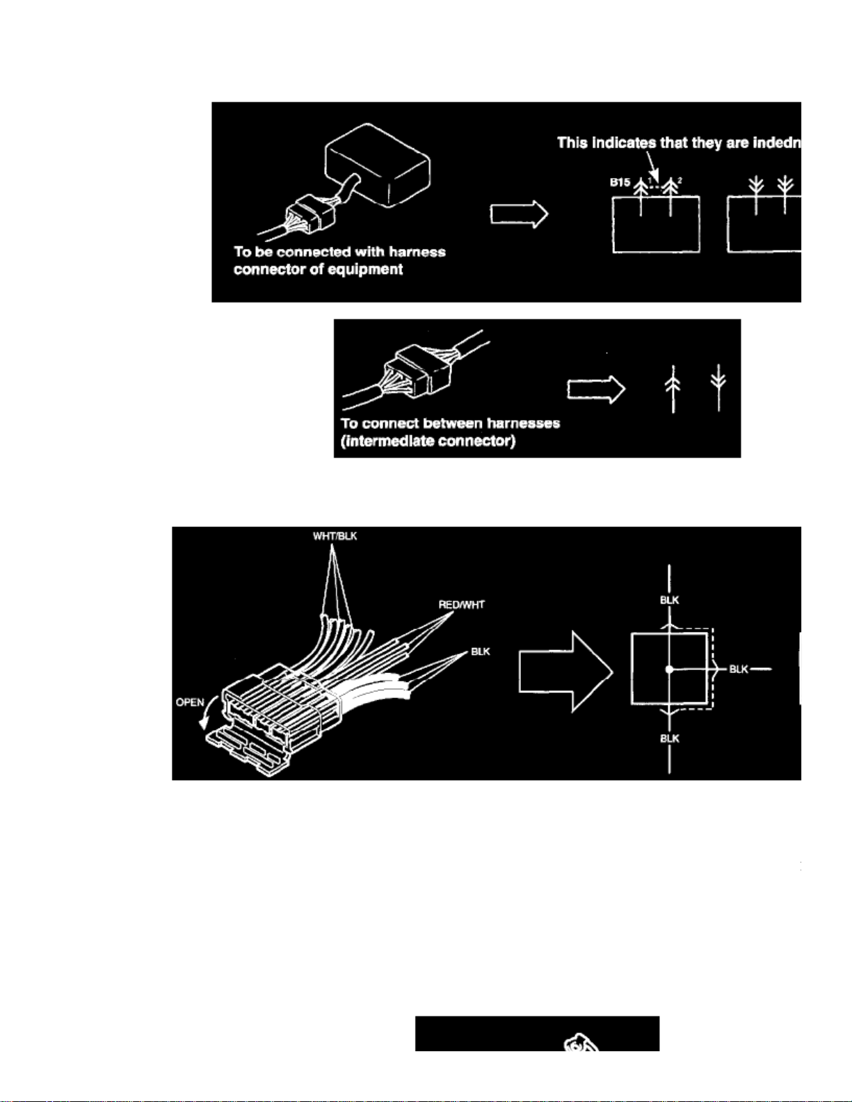
- There are three types of connectors with respect to the way it is connected and each type is illustrated as shown.
3.
Wiring of this vehicle uses joint connectors (J/C) which divide one wire into several different wires or combine several different wires into onewire.
The pin numbers for joint connectors are omitted because all the same color wires are connected with each other inside the joint connectors, thestructure of which can be seen by opening the connector head as shown.
- The joint connectors is illustrated.
Precautions
CAUTIONS IN SERVICING
When performing works related to electric Systems, observe following cautions for the purpose of protection of electrical parts and prevention of a firefrom occurrence.
Page 23
> Relays and Modules > Relays and Modules - Accessories and Optional Equipment > Keyless Entry Module > Component Information > Diagrams > Diagram Information
and Instructions > Page 18
Vitara JS (4Dr) 2WD L4-2.0L (2000)
-
OFF
When removing the battery from the vehicle or disconnecting the cable from the battery terminals for inspection or service works on the electricSystems, always confirm first that the ignition switch and all the other switches have been turned . Otherwise, the semi-conductor part may bedamaged.
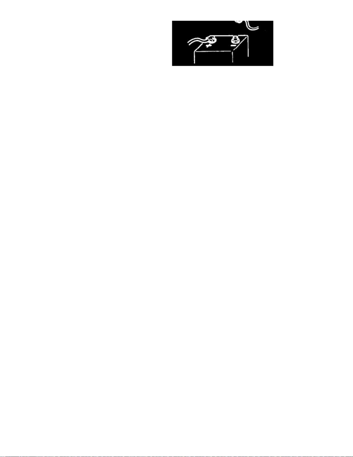
- When disconnecting cables from the battery, be sure to disconnect the one from the negative (-) terminal first and then the other from the positive
Page 24

(+) terminal.
- Reverse the above order when connecting the cables to the battery terminals.
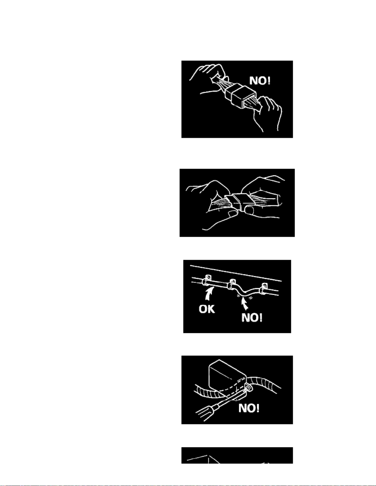
When disconnecting connectors, never pull the wiring harnesses. Unlock the connector lock first and then pull them apart by holding connectorsthemselves.
- When connecting connectors, also hold connectors and put them together until they lock securely (a click is heard).
- When installing the wiring harness, fix it with clamps so that no slack is left.
- When installing vehicle parts, be careful so that the wiring harness is not interfered with or caught by any other part.
Page 25

> Relays and Modules > Relays and Modules - Accessories and Optional Equipment > Keyless Entry Module > Component Information > Diagrams > Diagram Information
and Instructions > Page 19
Vitara JS (4Dr) 2WD L4-2.0L (2000)
- To avoid damage to the harness, protect its part which may contact against a part forming a sharp angle by winding tape or the like around it.
Page 26

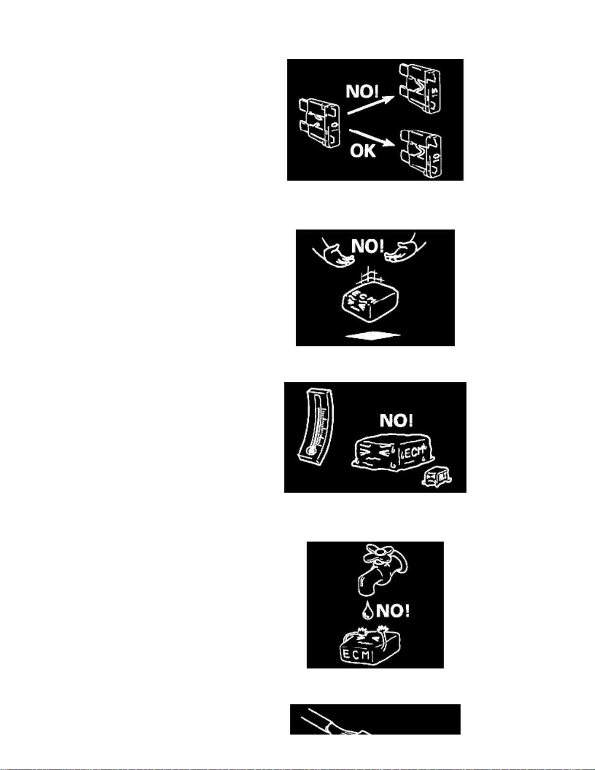
When replacing a fuse, make sure to use a fuse of the specified capacity. Use of a fuse with a larger capacity will cause a damage to the electricalparts and a fire.
- Always be careful not to handle electrical parts (computer, relay, etc.) in a rough manner or drop them.
-
80 C
When performing a work that produces a heat exceeding in the vicinity of the electrical parts, remove the heat sensitive electrical part(s)beforehand.
- Use care not to expose connectors and electrical parts to water which will be a cause of a trouble.
Page 27

> Relays and Modules > Relays and Modules - Accessories and Optional Equipment > Keyless Entry Module > Component Information > Diagrams > Diagram Information
and Instructions > Page 20
Vitara JS (4Dr) 2WD L4-2.0L (2000)
- When using a tester for checking continuity or measuring voltage, be sure to insert the tester probe from the wire harness side
Page 28

WARNING: This vehicle 18 equipped with Supplemental Inflatable Restraint Air Bag System. Service on or around Air Bag SystemComponents or Wiring must be performed only by an authorized Suzuki dealer. Please observe all the warnings described in the Air BagSystem Component and Wiring Location View mentioned in FOREWORD before performing service on or around Air Bag SystemComponents or Wiring Failure to follow WARNING could result In unintended air bag deployment or could render the air bag inoperative.Either of these two conditions may result in severe injury.
Page 29

> Relays and Modules > Relays and Modules - Accessories and Optional Equipment > Keyless Entry Module > Component Information > Diagrams > Diagram Information
and Instructions > Page 21
Vitara JS (4Dr) 2WD L4-2.0L (2000)
Symbols And Marks
Wire Color Symbols
Page 30

Wire Color Symbols
Page 31

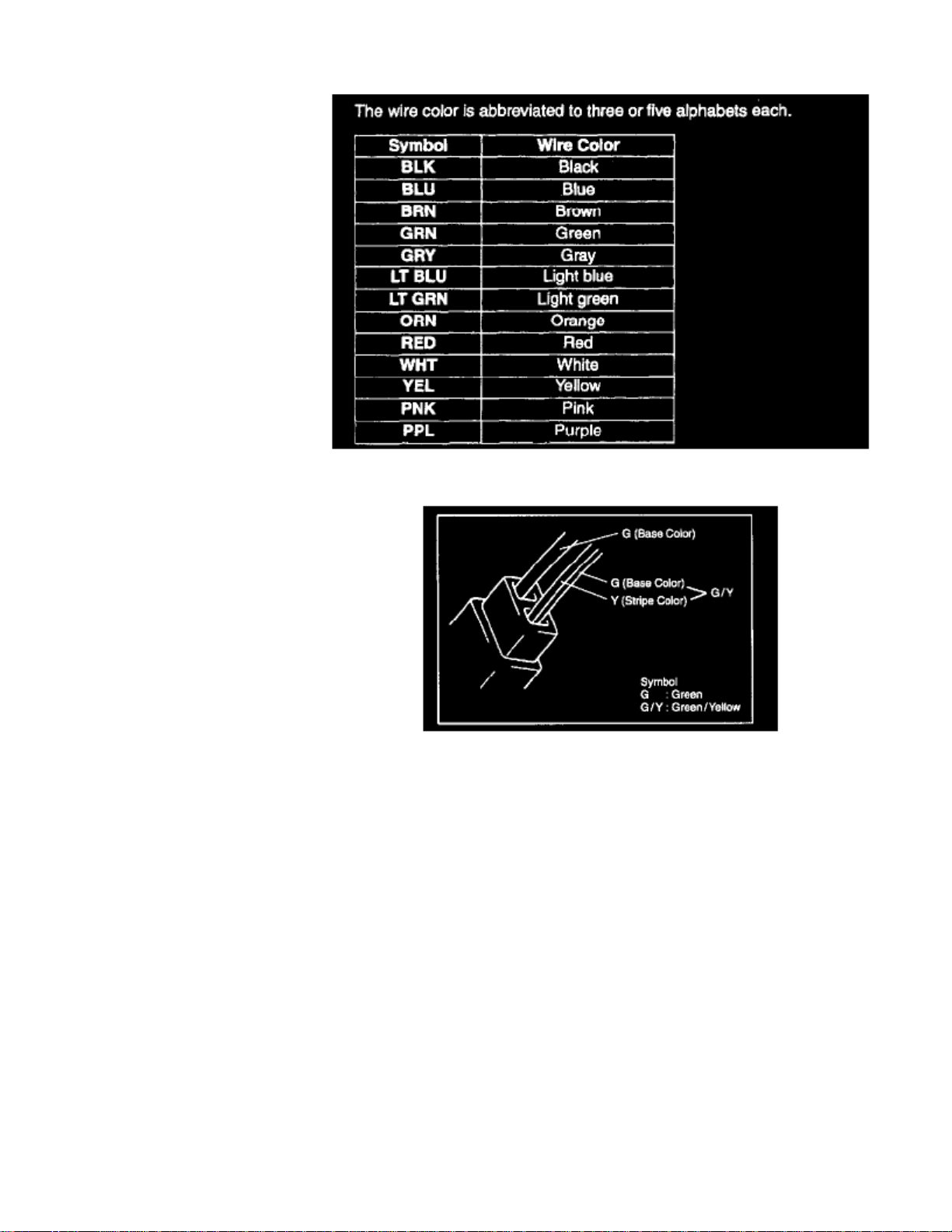
There are two kinds of colored wire used in this vehicle. One is single-colored wire and the other is dual-colored (striped) wire. As the color symbol, thesingle-colored wire uses three or five alphabets (i.e. "GRN"); the dual-colored wire uses two color symbols combination (i.e. "GRN/YEL"). The firstsymbol represents the base color of the wire ("GRN" in the figure) and the second symbol represents the color of the stripe (YEL" in the figure).
Page 32
> Relays and Modules > Relays and Modules - Accessories and Optional Equipment > Keyless Entry Module > Component Information > Diagrams > Diagram Information and Instructions > Page 22
Keyless Entry Module: Diagnostic Aids
Electrical Circuit Inspection Procedure
While there are various electrical circuit inspection methods, described here is a general method to check its open and short circuit by using an ohmmeterand a voltmeter.
OPEN CIRCUIT CHECK
Possible causes for the open circuit are as follows. As the cause is in the connector or terminal in many cases, they need to be checked particularlycarefully.
- Loose connection of connector
- Poor contact of terminal (due to dirt, corrosion or rust on it, poor contact tension, entry of foreign object etc.)
- Wire harness being open
When checking system circuits including an electronic control unit such as ECM, TCM, ABS control module, etc., it is important to perform carefulcheck, starting with items which are easier to check.
1. Disconnect negative (-) cable from battery2. Check each connector at both ends of the circuit being checked for loose connection. Also check lock condition of connector if equipped with
connector lock.
Page 33

> Relays and Modules > Relays and Modules - Accessories and Optional Equipment > Keyless Entry Module > Component Information > Diagrams > Diagram Information
and Instructions > Page 23
Vitara JS (4Dr) 2WD L4-2.0L (2000)
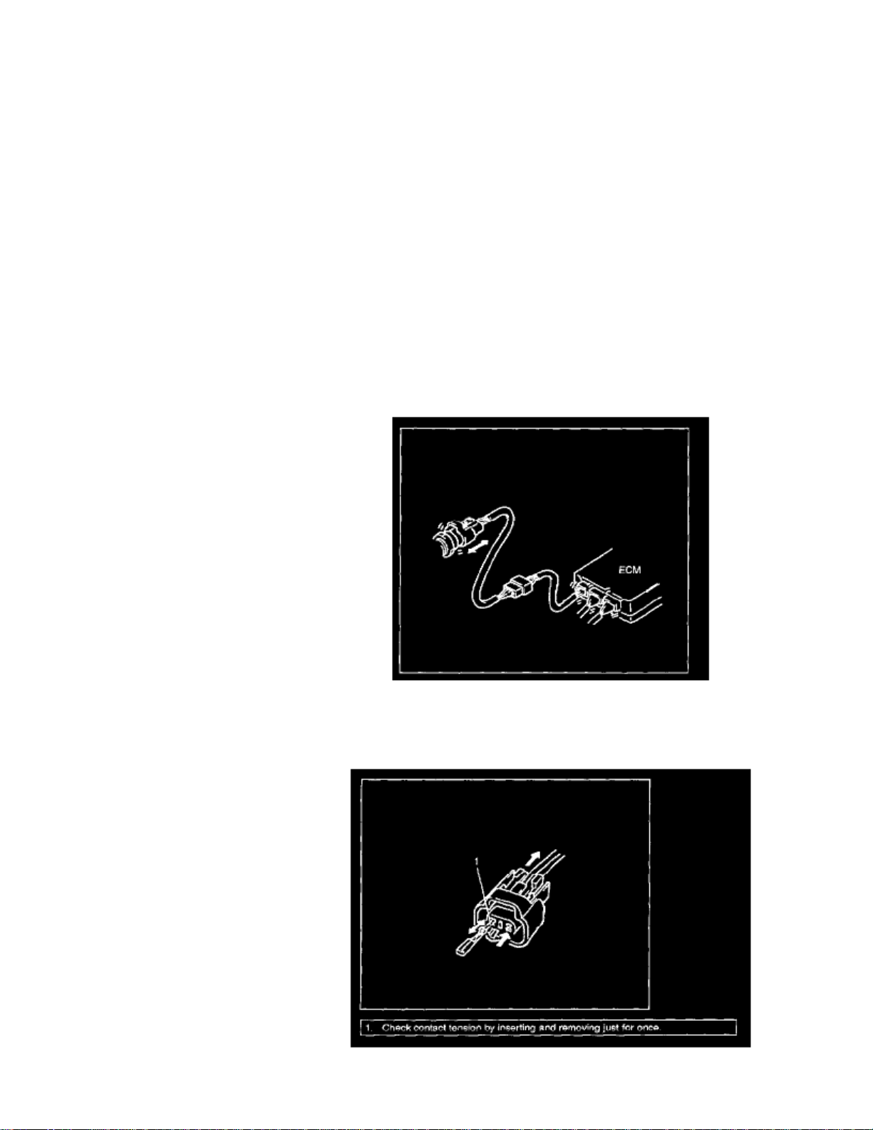
3. Using a test male terminal, check both terminals of the circuit being checked for contact tension of its female terminal. Check each terminal
visually for poor contact (possibly caused by dirt, corrosion, rust entry of foreign object, etc.). At the same time, check to make sure that eachterminal is locked in the connector fully.
Page 34
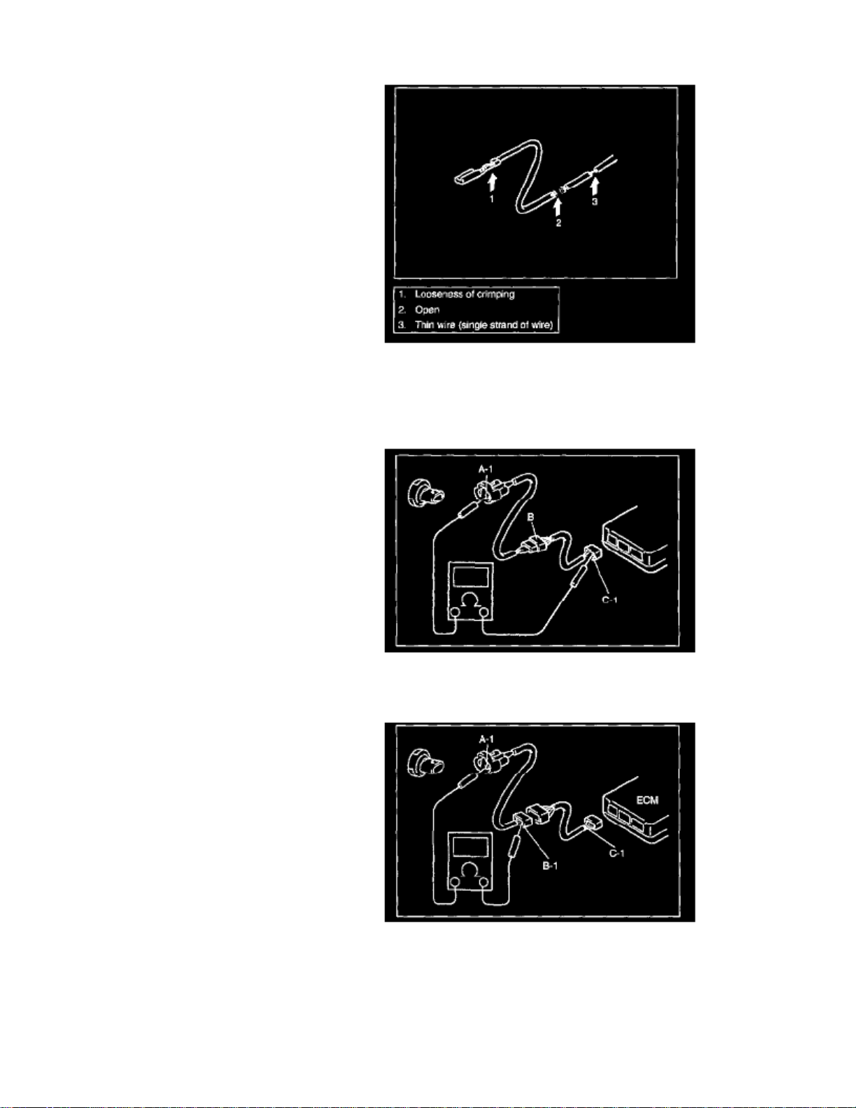
4. Using continuity check or voltage check the following procedure, check the wire harness for open circuit and poor connection with its terminals.
Locate abnormality, if any.
CONTINUITY CHECK
1. Measure resistance between connector terminals at both ends of the circuit being checked (between A-1 and C-1 in the figure). If no continuity is
indicated (infinity or over limit), that means that the circuit is open between terminals A-1 and C-1.
2. Disconnect the connector included in the circuit (connector-B in the figure) and measure resistance between terminals A-1 and B-1.
If no continuity is indicated, that means that the circuit is open between terminals A-1 and B-1. If continuity is indicated, there is an open circuitbetween terminals B-1 and C-1 or an abnormality in connector-B.
Page 35

> Relays and Modules > Relays and Modules - Accessories and Optional Equipment > Keyless Entry Module > Component Information > Diagrams > Diagram Information
and Instructions > Page 24
Vitara JS (4Dr) 2WD L4-2.0L (2000)
VOLTAGE CHECK
If voltage is supplied to the circuit being checked, voltage check can be used as circuit check.
Page 36
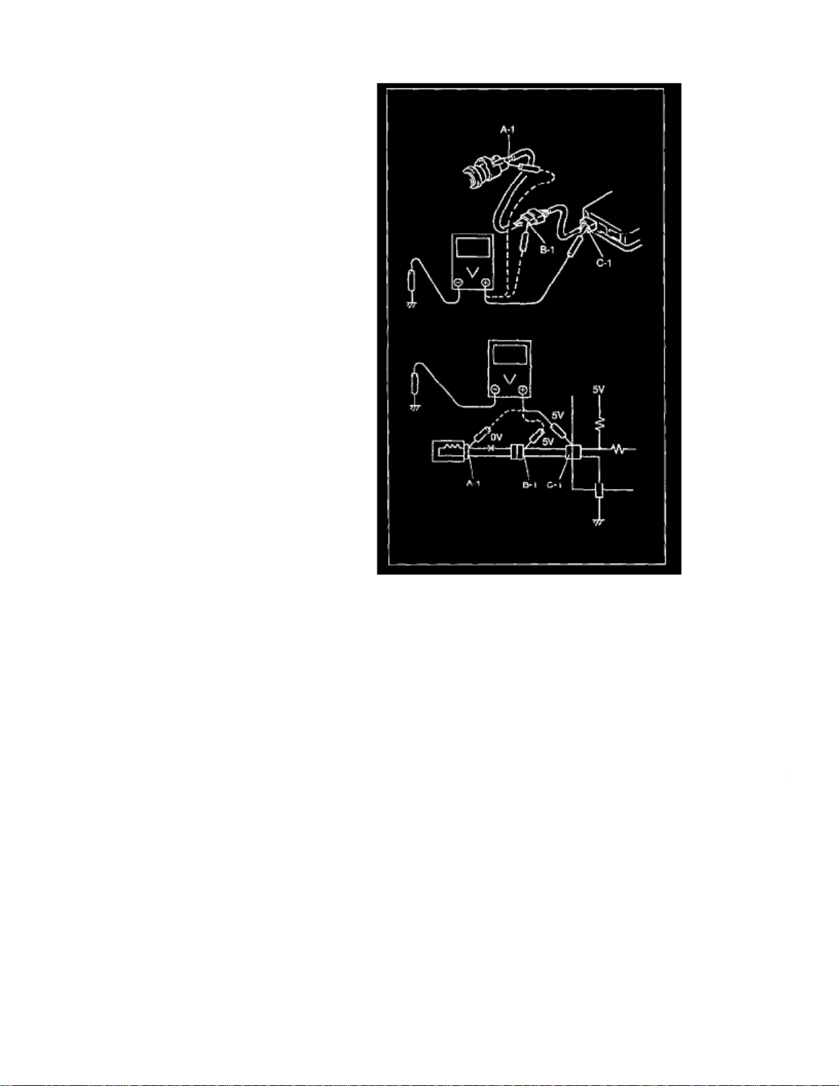
1. With all connectors connected and voltage applied to the circuit being checked, measure voltage between each terminal and body ground.
a. If measurements were taken as shown in the figure and results were as listed below, it means that the circuit is open between terminals B-1 and
A-1.
b. Also, if measured values were as listed below, it means that there is a resistance (abnormality) of such level that corresponds to the voltage
drop in the circuit between terminals A-1 and B-1.
5 V 5 V... 2 V
Voltage between:C-1 and body ground : Approx. B-1 and body ground : Approx. voltage dropA-1 and body ground : Approx. voltage drop3 V... 2 V
SHORT CIRCUIT CHECK (WIRE HARNESS TO GROUND)
Page 37

> Relays and Modules > Relays and Modules - Accessories and Optional Equipment > Keyless Entry Module > Component Information > Diagrams > Diagram Information
and Instructions > Page 25
Vitara JS (4Dr) 2WD L4-2.0L (2000)
5 V
Voltage between:C-1 and body ground : Approx. B-1 and body ground : Approx. A-1 and body ground : 5 V 0 V
Page 38

1. Disconnect negative (-) cable at battery.2. Disconnect connectors at both ends of the circuit to be checked.
If the circuit to be checked is connected to other parts (1), disconnect all connectors of those parts. Otherwise, diagnosis will be misled.NOTE:
3. Measure resistance between terminal at one end of circuit (A-1 terminal in the figure) and body ground. If continuity is indicated, it means that
there is a short to ground between terminals A-1 and C-1 of the circuit.
4. Disconnect the connector included in circuit (connector B) and measure resistance between A-1 and body ground. If continuity is indicated, it
means that the circuit is shorted to the ground between terminals A-2 and B-1.
Intermittent and Poor Connection
Most intermittent are caused by faulty electrical connections or wiring, although a sticking relay or solenoid can occasionally be at fault. When checkingit for proper connection, perform careful check of suspect circuits for:
Page 39

> Relays and Modules > Relays and Modules - Accessories and Optional Equipment > Keyless Entry Module > Component Information > Diagrams > Diagram Information
and Instructions > Page 26
Vitara JS (4Dr) 2WD L4-2.0L (2000)
- Poor mating of connector halves, or terminals not fully seated in the connector body (backed out).
Page 40

Dirt or corrosion on the terminals. The terminals must be clean and free of any foreign material which could impede proper terminal contact.However, cleaning the terminal with a sand paper or the like is prohibited.
Damaged connector body, exposing the terminals to moisture and dirt, as well as not maintaining proper terminal orientation with the componentor mating connector.
-
Improperly formed or damaged terminals.Check each connector terminal in problem circuits carefully to ensure good contact tension by using the corresponding mating terminal.If contact tension is not enough, reform it to increase contact tension or replace.
-
Poor terminal-to-wire connection.Check each wire harness in problem circuits for poor connection by shaking it by hand lightly. If any abnormal condition is found, repair orreplace.
Page 41

- Wire insulation which is rubbed through, causing an intermittent short as the bare area touches other wiring or parts of the vehicle.
-
Wiring broken inside the insulation. This condition could cause continuity check to show a good circuit, but if only 1 or 2 strands of amulti-strand-type wire are intact, resistance could be far too high.If any abnormality is found, repair or replace.
Page 42

> Relays and Modules > Relays and Modules - Body and Frame > Keyless Entry Module > Component Information > Locations
Page 43

Instrument Panel
Page 44

> Relays and Modules > Relays and Modules - Body and Frame > Keyless Entry Module > Component Information > Diagrams > Diagram Information and Instructions
Keyless Entry Module: Diagram Information and Instructions
Page 45

> Relays and Modules > Relays and Modules - Body and Frame > Keyless Entry Module > Component Information > Diagrams > Diagram Information and Instructions >
Page 33
Vitara JS (4Dr) 2WD L4-2.0L (2000)
Body Electrical System
Page 46

The wire color is abbreviated to the first (or first two) alphabet(s) of each color.
There are two kinds of colored wire used in this vehicle. One is single-colored wire and the other is dual-colored (striped) wire. The single-colored wireuses only one color symbol (i.e. "G"). The dual-colored wire uses two color symbols (i.e. "G/Y"). The first symbol represents the base color of the wire("G" in the figure) and the second symbol represents the color of the stripe ("Y" in the figure).
How to Locate Ground Point
Page 47

> Relays and Modules > Relays and Modules - Body and Frame > Keyless Entry Module > Component Information > Diagrams > Diagram Information and Instructions >
Page 34
Vitara JS (4Dr) 2WD L4-2.0L (2000)
Page 48

Look in ("GROUND POINT") for the black circle with the same numerical figure as the one described ("SYSTEM CIRCUIT DIAGRAM").
If there is an electrical part whose ground point Is not found In ("GROUND POINT"), that part Itself serves as a ground.NOTE:
How to Read Connector Codes and Pin NOS.
Page 49

> Relays and Modules > Relays and Modules - Body and Frame > Keyless Entry Module > Component Information > Diagrams > Diagram Information and Instructions >
Page 35
Vitara JS (4Dr) 2WD L4-2.0L (2000)
Page 50

It is possible to retrieve the location and shape of each connector from the connector code indicated in ("SYSTEM CIRCUIT DIAGRAM") and theposition of each pin from the connector pin No.
To Retrieve Location of Connector:
Open ("SYSTEM CIRCUIT DIAGRAM") to consult the connector code of the questioned connector. Then, refer to ("CONNECTOR LAYOUTDIAGRAM") and look for the same code as the connector code in question. The place where the code is found is the location of that connector.
To Retrieve Shape or Pin No.:
Open ("SYSTEM CIRCUIT DIAGRAM") to consult the connector code and pin No. of the connector of interest. Then, refer to ("LIST OFCONNECTORS") as shown at the right in the figure and look for the desired connector code where the shape of that connector is shown. This method isconvenient when locating the connector of interest among similar connectors. Also, by using this information, it is possible to find the position of eachpin from the connector pin No. provided in ("SYSTEM CIRCUIT DIAGRAM"). It is helpful when retrieving pin position in the connector for checkingcontinuity between pins.
To know the location, shape or pin position of the connector, cross-refer ("SYSTEM CIRCUIT DIAGRAM"),("CONNECTOR LAYOUT DIAGRAM")and ("LIST OF CONNECTORS") as follows:
How to Read Connector Layout Diagram
Page 51

> Relays and Modules > Relays and Modules - Body and Frame > Keyless Entry Module > Component Information > Diagrams > Diagram Information and Instructions >
Page 36
Vitara JS (4Dr) 2WD L4-2.0L (2000)
Page 52
When necessary to know the location of an electrical part or intermediate connector, it is easily possible to retrieve it by this diagram.
First consult ("SYSTEM CIRCUIT DIAGRAM") or connector table for the connector code of interest. Second refer to the diagrams and look for thesame code. More information on use of the code is illustrated below.
[A-1]:
Harness symbol and corresponding harness name
A: Battery cableB: A/C harnessC: Engine harnessD: Injector harnessE: Main harness
Oil pressure wire Console wire
G: Instrument panel harnessJ: Front and rear door harnessK: Roof wire
Spot light wire
L: Floor harnessO: Back door harness License light wire
High mounted stop light wire
Page 53

> Relays and Modules > Relays and Modules - Body and Frame > Keyless Entry Module > Component Information > Diagrams > Diagram Information and Instructions >
Page 37
Vitara JS (4Dr) 2WD L4-2.0L (2000)
Q: Air bag harnessR: Fuel pump harness
[A-2]:
Connector Number (Serial number: 01)
[B]:
This indicates the intermediate connector.Nos. are given to male and female connectors respectively. When the harness symbol (alphabet) is different, so is the harness name. (For the details, referto [A-1] above.)
Page 54

[C]:
This indicates the connector code.The connector code in the parentheses () has the same meaning as the above intermediate connector and at the same time, it indicates that there is aharness continuity ("CONNECTOR LAYOUT DIAGRAM"). That is, it suggests that the harness is continued to the other illustration and the continuedharness can be identified by the same connector code.
[D]:
This indicates the ground point No.The same No. is used as the ground point. (For the details, refer to ("GROUND POINT").)
How to Read Ground Point
Ground point means the position where the negative harness among wiring harnesses is grounded. The diagram in ("GROUND POINT") shows suchground points. In ("SYSTEM CIRCUIT DIAGRAM"), there are many ground marks followed by black circles with numerical figures in them whichmean that the end of the harness with such black circle is grounded to some part of the vehicle.
To locate the ground point (installation position), refer to ("GROUND POINT").
How to Read Power Supply Diagram
Page 55

> Relays and Modules > Relays and Modules - Body and Frame > Keyless Entry Module > Component Information > Diagrams > Diagram Information and Instructions >
Page 38
Vitara JS (4Dr) 2WD L4-2.0L (2000)
Page 56

Power supply diagram shows the circuit from the positive terminal of the battery to each fuse in the box and where each fuse is connected (each systemcircuit name). In addition, the electric load value of each fuse is indicated.
Since every ("SYSTEM CIRCUIT DIAGRAM") is drawn from the circuit down the fuse, cross-refer to ("POWER SUPPLY DIAGRAM") for thecontinuity of the upper circuit referring to fuse No. at each fuse symbol mark.
How to Read System Circuit Diagram
Page 57

> Relays and Modules > Relays and Modules - Body and Frame > Keyless Entry Module > Component Information > Diagrams > Diagram Information and Instructions >
Page 39
Vitara JS (4Dr) 2WD L4-2.0L (2000)
Page 58

The circuit diagram of each system shows the electric circuit from the main fuse, fuse box or the ignition switch (at the top in the diagram) to the ground(at the bottom) so that the circuit can be followed easily when performing inspection and service work.
Further information on connector, ground point and fuses is provided by cross-reference of "SYSTEM CIRCUIT DIAGRAM" and the other Systems asdescribed in the preceding indications.
Connector code, ground No. and fuse No. are the reference code for cross-reference.
[A]: Fuse No.
This No. indicates the reference code to power supply diagram. (Refer to ("POWER SUPPLY DIAGRAM") for the continuity of the upper circuit.)
[B]: Connector mark
This indicates that the connector is identical.
[C]:
Variations by specifications are identified by codes.
Page 59

> Relays and Modules > Relays and Modules - Body and Frame > Keyless Entry Module > Component Information > Diagrams > Diagram Information and Instructions >
Page 40
Vitara JS (4Dr) 2WD L4-2.0L (2000)
[D]:
This indicates continuity between the same symbols.
[E]: Wire color
This indicates the wire color. (Refer to "WIRE COLOR SYMBOLS".)
[F]:
This indicates the variations by the specifications.
Page 60

[G]:
This indicates that the circuit is continued to the same symbol.
[H]:
This indicates that the shield wire.
[I]: Ground point
This indicates the ground No. (Refer to ("GROUND POINT") for the location.)
[J]: Symbol mark
Symbol marks are used for better legibility. For more information, refer to "SYMBOLS AND MARKS".
[K]: Identical marks
This indicates that the intermediate connector is identical.
[L]:
This indicates variation of circuit depending on specifications.
[M]: Connector code
This indicates the reference code to ("CONNECTOR LAYOUT DIAGRAM") or ("LIST OF CONNECTORS") for further information.
[N]: Pin No.
This indicates the pin No. (Refer to ("LIST OF CONNECTORS") for the pin position in the connector.)
Indication of Connectors and How to Read Them
1.
- The male terminal and female terminal are identified by a double enclosure and a single one respectively.
-
Page 61

> Relays and Modules > Relays and Modules - Body and Frame > Keyless Entry Module > Component Information > Diagrams > Diagram Information and Instructions >
Page 41
Vitara JS (4Dr) 2WD L4-2.0L (2000)
The connectors are indicated as shown below in ("SYSTEM CIRCUIT DIAGRAM"). For the shape and pin arrangement of each connector used, referto ("LIST OF CONNECTORS"). Described below are how they are indicated and how to read them
The intermediate connector which connects harnesses is shown by both shapes of the male terminal and the female terminal but the connector to beconnected directly to the equipment is shown by the shape of the connector on the harness side.- The connectors described are always "harness side connectors" which are viewed from the direction as shown at the right.
Page 62

2.
- There are three types of connectors with respect to the way it is connected and each type is illustrated as shown.
3.
Wiring of this vehicle uses joint connectors (J/C) which divide one wire into several different wires or combine several different wires into onewire.
The pin numbers for joint connectors are omitted because all the same color wires are connected with each other inside the joint connectors, thestructure of which can be seen by opening the connector head as shown.
- The joint connectors is illustrated.
Precautions
CAUTIONS IN SERVICING
When performing works related to electric Systems, observe following cautions for the purpose of protection of electrical parts and prevention of a firefrom occurrence.
Page 63

> Relays and Modules > Relays and Modules - Body and Frame > Keyless Entry Module > Component Information > Diagrams > Diagram Information and Instructions >
Page 42
Vitara JS (4Dr) 2WD L4-2.0L (2000)
-
OFF
When removing the battery from the vehicle or disconnecting the cable from the battery terminals for inspection or service works on the electricSystems, always confirm first that the ignition switch and all the other switches have been turned . Otherwise, the semi-conductor part may bedamaged.
- When disconnecting cables from the battery, be sure to disconnect the one from the negative (-) terminal first and then the other from the positive
Page 64
(+) terminal.
- Reverse the above order when connecting the cables to the battery terminals.
When disconnecting connectors, never pull the wiring harnesses. Unlock the connector lock first and then pull them apart by holding connectorsthemselves.
- When connecting connectors, also hold connectors and put them together until they lock securely (a click is heard).
- When installing the wiring harness, fix it with clamps so that no slack is left.
- When installing vehicle parts, be careful so that the wiring harness is not interfered with or caught by any other part.
Page 65

> Relays and Modules > Relays and Modules - Body and Frame > Keyless Entry Module > Component Information > Diagrams > Diagram Information and Instructions >
Page 43
Vitara JS (4Dr) 2WD L4-2.0L (2000)
- To avoid damage to the harness, protect its part which may contact against a part forming a sharp angle by winding tape or the like around it.
Page 66
When replacing a fuse, make sure to use a fuse of the specified capacity. Use of a fuse with a larger capacity will cause a damage to the electricalparts and a fire.
- Always be careful not to handle electrical parts (computer, relay, etc.) in a rough manner or drop them.
-
80 C
When performing a work that produces a heat exceeding in the vicinity of the electrical parts, remove the heat sensitive electrical part(s)beforehand.
- Use care not to expose connectors and electrical parts to water which will be a cause of a trouble.
Page 67

> Relays and Modules > Relays and Modules - Body and Frame > Keyless Entry Module > Component Information > Diagrams > Diagram Information and Instructions >
Page 44
Vitara JS (4Dr) 2WD L4-2.0L (2000)
- When using a tester for checking continuity or measuring voltage, be sure to insert the tester probe from the wire harness side
Page 68

WARNING: This vehicle 18 equipped with Supplemental Inflatable Restraint Air Bag System. Service on or around Air Bag SystemComponents or Wiring must be performed only by an authorized Suzuki dealer. Please observe all the warnings described in the Air BagSystem Component and Wiring Location View mentioned in FOREWORD before performing service on or around Air Bag SystemComponents or Wiring Failure to follow WARNING could result In unintended air bag deployment or could render the air bag inoperative.Either of these two conditions may result in severe injury.
Page 69
> Relays and Modules > Relays and Modules - Body and Frame > Keyless Entry Module > Component Information > Diagrams > Diagram Information and Instructions >
Page 45
Vitara JS (4Dr) 2WD L4-2.0L (2000)
Symbols And Marks
Wire Color Symbols
Page 70
Wire Color Symbols
Page 71

There are two kinds of colored wire used in this vehicle. One is single-colored wire and the other is dual-colored (striped) wire. As the color symbol, thesingle-colored wire uses three or five alphabets (i.e. "GRN"); the dual-colored wire uses two color symbols combination (i.e. "GRN/YEL"). The firstsymbol represents the base color of the wire ("GRN" in the figure) and the second symbol represents the color of the stripe (YEL" in the figure).
Page 72

> Relays and Modules > Relays and Modules - Body and Frame > Keyless Entry Module > Component Information > Diagrams > Diagram Information and Instructions > Page 46
Keyless Entry Module: Diagnostic Aids
Electrical Circuit Inspection Procedure
While there are various electrical circuit inspection methods, described here is a general method to check its open and short circuit by using an ohmmeterand a voltmeter.
OPEN CIRCUIT CHECK
Possible causes for the open circuit are as follows. As the cause is in the connector or terminal in many cases, they need to be checked particularlycarefully.
- Loose connection of connector
- Poor contact of terminal (due to dirt, corrosion or rust on it, poor contact tension, entry of foreign object etc.)
- Wire harness being open
When checking system circuits including an electronic control unit such as ECM, TCM, ABS control module, etc., it is important to perform carefulcheck, starting with items which are easier to check.
1. Disconnect negative (-) cable from battery2. Check each connector at both ends of the circuit being checked for loose connection. Also check lock condition of connector if equipped with
connector lock.
Page 73

> Relays and Modules > Relays and Modules - Body and Frame > Keyless Entry Module > Component Information > Diagrams > Diagram Information and Instructions >
Page 47
Vitara JS (4Dr) 2WD L4-2.0L (2000)
3. Using a test male terminal, check both terminals of the circuit being checked for contact tension of its female terminal. Check each terminal
visually for poor contact (possibly caused by dirt, corrosion, rust entry of foreign object, etc.). At the same time, check to make sure that eachterminal is locked in the connector fully.
Page 74

4. Using continuity check or voltage check the following procedure, check the wire harness for open circuit and poor connection with its terminals.
Locate abnormality, if any.
CONTINUITY CHECK
1. Measure resistance between connector terminals at both ends of the circuit being checked (between A-1 and C-1 in the figure). If no continuity is
indicated (infinity or over limit), that means that the circuit is open between terminals A-1 and C-1.
2. Disconnect the connector included in the circuit (connector-B in the figure) and measure resistance between terminals A-1 and B-1.
If no continuity is indicated, that means that the circuit is open between terminals A-1 and B-1. If continuity is indicated, there is an open circuitbetween terminals B-1 and C-1 or an abnormality in connector-B.
Page 75

> Relays and Modules > Relays and Modules - Body and Frame > Keyless Entry Module > Component Information > Diagrams > Diagram Information and Instructions >
Page 48
Vitara JS (4Dr) 2WD L4-2.0L (2000)
VOLTAGE CHECK
If voltage is supplied to the circuit being checked, voltage check can be used as circuit check.
Page 76

1. With all connectors connected and voltage applied to the circuit being checked, measure voltage between each terminal and body ground.
a. If measurements were taken as shown in the figure and results were as listed below, it means that the circuit is open between terminals B-1 and
A-1.
b. Also, if measured values were as listed below, it means that there is a resistance (abnormality) of such level that corresponds to the voltage
drop in the circuit between terminals A-1 and B-1.
5 V 5 V... 2 V
Voltage between:C-1 and body ground : Approx. B-1 and body ground : Approx. voltage dropA-1 and body ground : Approx. voltage drop3 V... 2 V
SHORT CIRCUIT CHECK (WIRE HARNESS TO GROUND)
Page 77

> Relays and Modules > Relays and Modules - Body and Frame > Keyless Entry Module > Component Information > Diagrams > Diagram Information and Instructions >
Page 49
Vitara JS (4Dr) 2WD L4-2.0L (2000)
5 V
Voltage between:C-1 and body ground : Approx. B-1 and body ground : Approx. A-1 and body ground : 5 V 0 V
Page 78

1. Disconnect negative (-) cable at battery.2. Disconnect connectors at both ends of the circuit to be checked.
If the circuit to be checked is connected to other parts (1), disconnect all connectors of those parts. Otherwise, diagnosis will be misled.NOTE:
3. Measure resistance between terminal at one end of circuit (A-1 terminal in the figure) and body ground. If continuity is indicated, it means that
there is a short to ground between terminals A-1 and C-1 of the circuit.
4. Disconnect the connector included in circuit (connector B) and measure resistance between A-1 and body ground. If continuity is indicated, it
means that the circuit is shorted to the ground between terminals A-2 and B-1.
Intermittent and Poor Connection
Most intermittent are caused by faulty electrical connections or wiring, although a sticking relay or solenoid can occasionally be at fault. When checkingit for proper connection, perform careful check of suspect circuits for:
Page 79

> Relays and Modules > Relays and Modules - Body and Frame > Keyless Entry Module > Component Information > Diagrams > Diagram Information and Instructions >
Page 50
Vitara JS (4Dr) 2WD L4-2.0L (2000)
- Poor mating of connector halves, or terminals not fully seated in the connector body (backed out).
Page 80

Dirt or corrosion on the terminals. The terminals must be clean and free of any foreign material which could impede proper terminal contact.However, cleaning the terminal with a sand paper or the like is prohibited.
Damaged connector body, exposing the terminals to moisture and dirt, as well as not maintaining proper terminal orientation with the componentor mating connector.
-
Improperly formed or damaged terminals.Check each connector terminal in problem circuits carefully to ensure good contact tension by using the corresponding mating terminal.If contact tension is not enough, reform it to increase contact tension or replace.
-
Poor terminal-to-wire connection.Check each wire harness in problem circuits for poor connection by shaking it by hand lightly. If any abnormal condition is found, repair orreplace.
Page 81

- Wire insulation which is rubbed through, causing an intermittent short as the bare area touches other wiring or parts of the vehicle.
-
Wiring broken inside the insulation. This condition could cause continuity check to show a good circuit, but if only 1 or 2 strands of amulti-strand-type wire are intact, resistance could be far too high.If any abnormality is found, repair or replace.
Page 82

> Relays and Modules > Relays and Modules - Body and Frame > Power Door Lock Control Module > Component Information > Locations
Page 83

Instrument Panel
Page 84

> Relays and Modules > Relays and Modules - Body and Frame > Power Door Lock Control Module > Component Information > Locations > Page 54
Power Door Lock Control Module: Testing and Inspection
Power Door Lock Controller Inspection
1. Disconnect power door lock controller coupler.2. Connect (+) wire and (-) wire of 12 V battery (1) to terminal "A", "E" and "F" as shown in the figure.3. Disconnect cord from terminal "E" and connect it to terminal "G".4. Repeat Steps 2) and 3) several times and if relay operation is heard every time, it means that controller (2) is operating.
Page 85

Page 86
> Relays and Modules > Relays and Modules - Brakes and Traction Control > Electronic Brake Control Module > Component Information > Locations
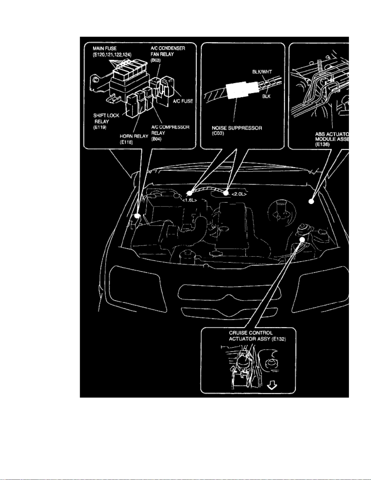
Engine Room Part 1
Page 87

Page 88

> Relays and Modules > Relays and Modules - Cruise Control > Cruise Control Module > Component Information > Testing and Inspection
Cruise Control Module: Testing and Inspection
CRUISE CONTROL MODULE AND ITS CIRCUIT INSPECTION
CAUTION:
Cruise control module can not be checked by itself. It is strictly prohibited to connect voltmeter or ohmmeter to cruise control module withcoupler disconnected from it.
Page 89

> Relays and Modules > Relays and Modules - Cruise Control > Cruise Control Module > Component Information > Testing and Inspection > Page 63
Vitara JS (4Dr) 2WD L4-2.0L (2000)
Throttle Opening Signal Voltage Characteristic
Voltage Check
Page 90

Check for input or output voltage of control module (voltage between each circuit and body ground) with cruise control module connector connected.
Resistance Check
1. Disconnect cruise control module coupler from cruise control module with ignition switch .OFF
Never touch terminals of cruise control module itself or connect voltmeter or ohmmeter.CAUTION:
2. Check resistance between each pair of terminals of disconnected couplers as listed in the table.
Page 91

Page 92

> Relays and Modules > Relays and Modules - HVAC > Blower Motor Relay > Component Information > Locations
Page 93

Instrument Panel
Page 94

> Relays and Modules > Relays and Modules - HVAC > Blower Motor Relay > Component Information > Locations > Page 68
Blower Motor Relay: Testing and Inspection
HEATER BLOWER RELAY INSPECTION
1. Connect battery positive (+) terminal to terminal "2" of relay.2. Connect battery negative (-) terminal to terminal "1" of relay.3. Check continuity between terminal "3" and "4".
If there is no continuity when relay is connected to the battery, replace relay.
Page 95

Page 96
> Relays and Modules > Relays and Modules - HVAC > Blower Motor Relay > Component Information > Locations > Page 69
Blower Motor Relay: Service and Repair
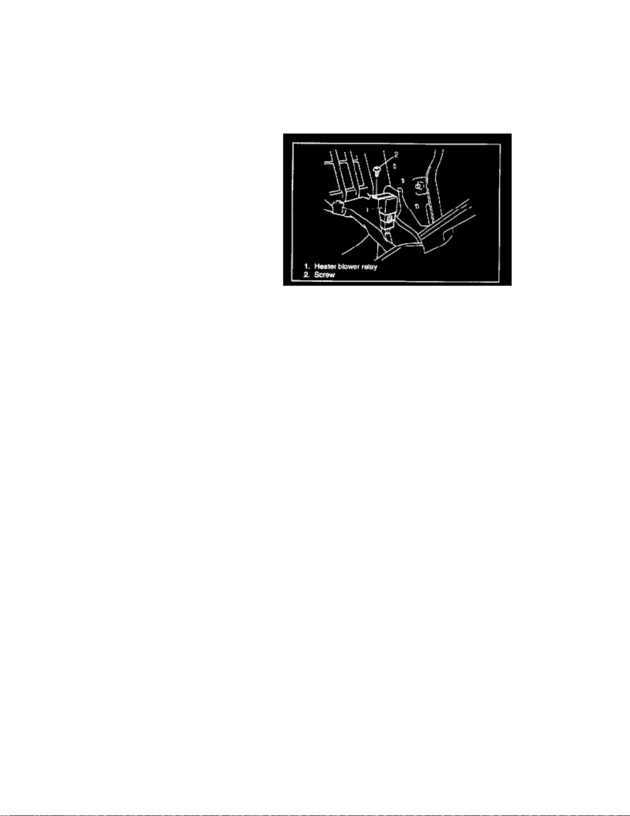
Heater Blower Relay
REMOVAL
Heater Blower Relay
1. Disconnect negative (-) cable at battery.2. Disable air bag system, if equipped.3. Open glove box, then remove screw.4. Remove glove box.5. Disconnect relay coupler.6. Remove heater blower relay by loosening its fastening screw.
INSTALLATION
1. Reverse removal procedure for installation.2. Enable air bag system, if equipped.
Page 97

Page 98

> Relays and Modules > Relays and Modules - HVAC > Compressor Clutch Relay > Component Information > Locations
Engine Room Part 1
Page 99

Page 100

> Relays and Modules > Relays and Modules - HVAC > Compressor Clutch Relay > Component Information > Locations > Page 73
Compressor Clutch Relay: Testing and Inspection
A/C COMPRESSOR RELAY INSPECTION
1. Disconnect negative cable at battery.2. Remove A/C compressor relay from vehicle.3. Connect battery positive (+) terminal to terminal "2" of relay. Connect battery negative (-) terminal to terminal "1" of relay. Check continuity
between terminal "3" and "4".If there is no continuity when relay is connected to the battery, replace relay.
 Loading...