

Page 1

suzuki :: Suzuki Swift GA L4-1298cc 1.3L SOHC
MFI (2001)
Page 2

> Relays and Modules > Relays and Modules - Accessories and Optional Equipment > Keyless Entry Module > Component Information > Technical Service Bulletins > All Technical Service Bulletins for Keyless Entry Module:
> TS02 > Dec > 04 > Keyless Entry - Remote Transmitter Inoperative
Keyless Entry Module: All Technical Service BulletinsKeyless Entry - Remote Transmitter Inoperative
Section Title: General Info.
TSB No. TS02 12164R
Division: Automotive
Category: General Tech Info
SUBJECT: PROGRAMMABLE KEYLESS ENTRY SYSTEM
MODEL(S): ALL
YEAR: 2001 - 2002
CONDITION: The Keyless Entry System is inoperative when using transmitter(s). Transmitter(s) battery is good.
CAUSE: The signals between the transmitter and the controller are no longer programmed together (unsynchronized).
CONDITION: 2001 - 2002 models: Use the applicable Service Manual to diagnose the concern. If diagnostics determine the transmitters(s) or controller need to bereplaced, install a new programmable Keyless Controller Set. Then use the programming procedure located in the KEYLESS ENTRY SYSTEMOWNER'S MANUAL SUPPLEMENT
REVISION: 2003 information removed due to confusion in the field. See appropriate Service Manual 2003 keyless entry system repair procedure.
Page 3

> Relays and Modules > Relays and Modules - Accessories and Optional Equipment > Keyless Entry Module > Component Information > Technical Service Bulletins > All
Technical Service Bulletins for Keyless Entry Module: > TS02 > Dec > 04 > Keyless Entry - Remote Transmitter Inoperative > Page 12
Swift GA L4-1298cc 1.3L SOHC MFI (2001)
PART(S) INFORMATION:
Page 4

2001 - 2002 MODELS
All 2001-2002 models with keyless entry Systems have a factory installed non-programmable controller assembly. This controller is identified by a whiteconnector (see picture shown) and only supports the original two transmitters provided with the vehicle. When replacing any component of the system, itrequires the replacement of the controller assembly and its transmitters as a set.
A new programmable controller is now available as a set for these 2001 - 2002 vehicles. The programmable controller is identified by a label stating"PROGRAMMABLE TRANSMITTER" and a grey connector as shown above.
NOTE:
The new controller can support up to 4 transmitters. Extra transmitters are available (see PARTS INFORMATION).
On these 2001-2002 models, perform the diagnostics located in the applicable Service Manual and if it states to replace the controller ortransmitter(s), be sure to install the new programmable Keyless Controller Set. Then program up to four(4) transmitters to the controller using theOwner's Manual Supplement instructions which is packed with the controller set.
NOTE:
After programming the transmitters to the controller, be sure to place the Keyless Entry System Owner's Manual Supplement in with the VehicleOwner's Manual. The customer will then have the information available to program their transmitters to their controller, if needed.
Disclaimer
Page 5

Page 6

> Relays and Modules > Relays and Modules - Accessories and Optional Equipment > Keyless Entry Module > Component Information > Technical Service Bulletins > All Technical Service Bulletins for Keyless Entry Module:
> TS02 > Sep > 02 > Keyless Entry System - Inoperative Using Transmitter
Keyless Entry Module: All Technical Service BulletinsKeyless Entry System - Inoperative Using Transmitter
Section Title: General Info. TSB No. TS 02 09112
Division: AutomotiveCategory: General Tech Info
SUBJECTPROGRAMMABLE KEYLESS ENTRY SYSTEM
MODEL(S):ALL
YEAR:2001 - 2003
CONDITION:
The Keyless Entry System is inoperative when using transmitter(s). Transmitter(s) battery is good.
CAUSE:
The signals between the transmitter and the controller are no longer programmed together (unsynchronized).
CORRECTION:
2003 models: These vehicles have a programmable controller. Use the applicable Service Manual to diagnose the concern. Replace only the individualcomponents as necessary. DO NOT install a set. Then use the programming procedure located in the Vehicle Owner's Manual.
2001 - 2002 models: Use the applicable Service Manual to diagnose the concern. If diagnostics determine the transmitters(s) or controller need to bereplaced, install a new programmable Keyless Controller Set. Then use the programming procedure located in the KEYLESS ENTRY SYSTEMOWNER'S MANUAL SUPPLEMENT packaged in the set.
Page 7

> Relays and Modules > Relays and Modules - Accessories and Optional Equipment > Keyless Entry Module > Component Information > Technical Service Bulletins > All
Technical Service Bulletins for Keyless Entry Module: > TS02 > Sep > 02 > Keyless Entry System - Inoperative Using Transmitter > Page 17
Swift GA L4-1298cc 1.3L SOHC MFI (2001)
Page 8

PART(S) INFORMATION:
2003 MODELS
These vehicles have the programmable Keyless Controller Assembly. Use the applicable Service Manual to diagnose the concern. For component partsrefer to 2003 Model Parts Catalog.
:NOTE
Replace only the individual components as necessary. DO NOT install a set.
2001 - 2002 MODELS
All 2001-2002 models with keyless entry systems have a factory installed non-programmable controller assembly. This controller is identified by a whiteconnector (see picture) and only supports the original two transmitters provided with the vehicle. When servicing any component of the system or iftransmitters are misplaced it requires the replacement of the controller assembly and its transmitters as a set.
A new programmable controller is now available as a set for these 2001 - 2002 vehicles. The programmable controller is identified by a label stating"PROGRAMMABLE TRANSMITTER" and a grey connector as shown.
:NOTE
The new controller can support up to 4 transmitters. Extra transmitters are available (see PARTS INFORMATION).
On these 2001-2002 models, perform the diagnostics located in the applicable Service Manual and if it states to replace the controller or transmitter(s),be sure to install the new programmable Keyless Controller Set. Then program up to four (4) transmitters to the controller using the Owner's ManualSupplement instructions which is packed with the controller set.
:NOTE
After programming the transmitters to the controller; be sure to place the Keyless Entry System Owner's Manual Supplement in with the VehicleOwner's Manual. The customer will then have the information available to program their transmitters to their controller, if needed.
Disclaimer
Page 9

Page 10

> Relays and Modules > Relays and Modules - Accessories and Optional Equipment > Keyless Entry Module > Component Information > Technical Service Bulletins > Customer Interest for Keyless Entry Module: > TS02 >
Dec > 04 > Keyless Entry - Remote Transmitter Inoperative
Keyless Entry Module: Customer InterestKeyless Entry - Remote Transmitter Inoperative
Section Title: General Info.
TSB No. TS02 12164R
Division: Automotive
Category: General Tech Info
SUBJECT: PROGRAMMABLE KEYLESS ENTRY SYSTEM
MODEL(S): ALL
YEAR: 2001 - 2002
CONDITION: The Keyless Entry System is inoperative when using transmitter(s). Transmitter(s) battery is good.
CAUSE: The signals between the transmitter and the controller are no longer programmed together (unsynchronized).
CONDITION: 2001 - 2002 models: Use the applicable Service Manual to diagnose the concern. If diagnostics determine the transmitters(s) or controller need to bereplaced, install a new programmable Keyless Controller Set. Then use the programming procedure located in the KEYLESS ENTRY SYSTEMOWNER'S MANUAL SUPPLEMENT
REVISION: 2003 information removed due to confusion in the field. See appropriate Service Manual 2003 keyless entry system repair procedure.
Page 11

> Relays and Modules > Relays and Modules - Accessories and Optional Equipment > Keyless Entry Module > Component Information > Technical Service Bulletins >
Customer Interest for Keyless Entry Module: > TS02 > Dec > 04 > Keyless Entry - Remote Transmitter Inoperative > Page 23
Swift GA L4-1298cc 1.3L SOHC MFI (2001)
PART(S) INFORMATION:
Page 12

2001 - 2002 MODELS
All 2001-2002 models with keyless entry Systems have a factory installed non-programmable controller assembly. This controller is identified by a whiteconnector (see picture shown) and only supports the original two transmitters provided with the vehicle. When replacing any component of the system, itrequires the replacement of the controller assembly and its transmitters as a set.
A new programmable controller is now available as a set for these 2001 - 2002 vehicles. The programmable controller is identified by a label stating"PROGRAMMABLE TRANSMITTER" and a grey connector as shown above.
NOTE:
The new controller can support up to 4 transmitters. Extra transmitters are available (see PARTS INFORMATION).
On these 2001-2002 models, perform the diagnostics located in the applicable Service Manual and if it states to replace the controller ortransmitter(s), be sure to install the new programmable Keyless Controller Set. Then program up to four(4) transmitters to the controller using theOwner's Manual Supplement instructions which is packed with the controller set.
NOTE:
After programming the transmitters to the controller, be sure to place the Keyless Entry System Owner's Manual Supplement in with the VehicleOwner's Manual. The customer will then have the information available to program their transmitters to their controller, if needed.
Disclaimer
Page 13

Page 14

> Relays and Modules > Relays and Modules - Accessories and Optional Equipment > Keyless Entry Module > Component Information > Technical Service Bulletins > Customer Interest for Keyless Entry Module: > TS02 >
Sep > 02 > Keyless Entry System - Inoperative Using Transmitter
Keyless Entry Module: Customer InterestKeyless Entry System - Inoperative Using Transmitter
Section Title: General Info. TSB No. TS 02 09112
Division: AutomotiveCategory: General Tech Info
SUBJECTPROGRAMMABLE KEYLESS ENTRY SYSTEM
MODEL(S):ALL
YEAR:2001 - 2003
CONDITION:
The Keyless Entry System is inoperative when using transmitter(s). Transmitter(s) battery is good.
CAUSE:
The signals between the transmitter and the controller are no longer programmed together (unsynchronized).
CORRECTION:
2003 models: These vehicles have a programmable controller. Use the applicable Service Manual to diagnose the concern. Replace only the individualcomponents as necessary. DO NOT install a set. Then use the programming procedure located in the Vehicle Owner's Manual.
2001 - 2002 models: Use the applicable Service Manual to diagnose the concern. If diagnostics determine the transmitters(s) or controller need to bereplaced, install a new programmable Keyless Controller Set. Then use the programming procedure located in the KEYLESS ENTRY SYSTEMOWNER'S MANUAL SUPPLEMENT packaged in the set.
Page 15

> Relays and Modules > Relays and Modules - Accessories and Optional Equipment > Keyless Entry Module > Component Information > Technical Service Bulletins >
Customer Interest for Keyless Entry Module: > TS02 > Sep > 02 > Keyless Entry System - Inoperative Using Transmitter > Page 28
Swift GA L4-1298cc 1.3L SOHC MFI (2001)
Page 16

PART(S) INFORMATION:
2003 MODELS
These vehicles have the programmable Keyless Controller Assembly. Use the applicable Service Manual to diagnose the concern. For component partsrefer to 2003 Model Parts Catalog.
:NOTE
Replace only the individual components as necessary. DO NOT install a set.
2001 - 2002 MODELS
All 2001-2002 models with keyless entry systems have a factory installed non-programmable controller assembly. This controller is identified by a whiteconnector (see picture) and only supports the original two transmitters provided with the vehicle. When servicing any component of the system or iftransmitters are misplaced it requires the replacement of the controller assembly and its transmitters as a set.
A new programmable controller is now available as a set for these 2001 - 2002 vehicles. The programmable controller is identified by a label stating"PROGRAMMABLE TRANSMITTER" and a grey connector as shown.
:NOTE
The new controller can support up to 4 transmitters. Extra transmitters are available (see PARTS INFORMATION).
On these 2001-2002 models, perform the diagnostics located in the applicable Service Manual and if it states to replace the controller or transmitter(s),be sure to install the new programmable Keyless Controller Set. Then program up to four (4) transmitters to the controller using the Owner's ManualSupplement instructions which is packed with the controller set.
:NOTE
After programming the transmitters to the controller; be sure to place the Keyless Entry System Owner's Manual Supplement in with the VehicleOwner's Manual. The customer will then have the information available to program their transmitters to their controller, if needed.
Disclaimer
Page 17

Page 18

> Relays and Modules > Relays and Modules - Body and Frame > Keyless Entry Module > Component Information > Technical Service Bulletins > All Technical Service Bulletins for Keyless Entry Module: > TS02 > Dec > 04
> Keyless Entry - Remote Transmitter Inoperative
Keyless Entry Module: All Technical Service BulletinsKeyless Entry - Remote Transmitter Inoperative
Section Title: General Info.
TSB No. TS02 12164R
Division: Automotive
Category: General Tech Info
SUBJECT: PROGRAMMABLE KEYLESS ENTRY SYSTEM
MODEL(S): ALL
YEAR: 2001 - 2002
CONDITION: The Keyless Entry System is inoperative when using transmitter(s). Transmitter(s) battery is good.
CAUSE: The signals between the transmitter and the controller are no longer programmed together (unsynchronized).
CONDITION: 2001 - 2002 models: Use the applicable Service Manual to diagnose the concern. If diagnostics determine the transmitters(s) or controller need to bereplaced, install a new programmable Keyless Controller Set. Then use the programming procedure located in the KEYLESS ENTRY SYSTEMOWNER'S MANUAL SUPPLEMENT
REVISION: 2003 information removed due to confusion in the field. See appropriate Service Manual 2003 keyless entry system repair procedure.
Page 19

> Relays and Modules > Relays and Modules - Body and Frame > Keyless Entry Module > Component Information > Technical Service Bulletins > All Technical Service
Bulletins for Keyless Entry Module: > TS02 > Dec > 04 > Keyless Entry - Remote Transmitter Inoperative > Page 38
Swift GA L4-1298cc 1.3L SOHC MFI (2001)
PART(S) INFORMATION:
Page 20

2001 - 2002 MODELS
All 2001-2002 models with keyless entry Systems have a factory installed non-programmable controller assembly. This controller is identified by a whiteconnector (see picture shown) and only supports the original two transmitters provided with the vehicle. When replacing any component of the system, itrequires the replacement of the controller assembly and its transmitters as a set.
A new programmable controller is now available as a set for these 2001 - 2002 vehicles. The programmable controller is identified by a label stating"PROGRAMMABLE TRANSMITTER" and a grey connector as shown above.
NOTE:
The new controller can support up to 4 transmitters. Extra transmitters are available (see PARTS INFORMATION).
On these 2001-2002 models, perform the diagnostics located in the applicable Service Manual and if it states to replace the controller ortransmitter(s), be sure to install the new programmable Keyless Controller Set. Then program up to four(4) transmitters to the controller using theOwner's Manual Supplement instructions which is packed with the controller set.
NOTE:
After programming the transmitters to the controller, be sure to place the Keyless Entry System Owner's Manual Supplement in with the VehicleOwner's Manual. The customer will then have the information available to program their transmitters to their controller, if needed.
Disclaimer
Page 21

Page 22

> Relays and Modules > Relays and Modules - Body and Frame > Keyless Entry Module > Component Information > Technical Service Bulletins > All Technical Service Bulletins for Keyless Entry Module: > TS02 > Sep > 02
> Keyless Entry System - Inoperative Using Transmitter
Keyless Entry Module: All Technical Service BulletinsKeyless Entry System - Inoperative Using Transmitter
Section Title: General Info. TSB No. TS 02 09112
Division: AutomotiveCategory: General Tech Info
SUBJECTPROGRAMMABLE KEYLESS ENTRY SYSTEM
MODEL(S):ALL
YEAR:2001 - 2003
CONDITION:
The Keyless Entry System is inoperative when using transmitter(s). Transmitter(s) battery is good.
CAUSE:
The signals between the transmitter and the controller are no longer programmed together (unsynchronized).
CORRECTION:
2003 models: These vehicles have a programmable controller. Use the applicable Service Manual to diagnose the concern. Replace only the individualcomponents as necessary. DO NOT install a set. Then use the programming procedure located in the Vehicle Owner's Manual.
2001 - 2002 models: Use the applicable Service Manual to diagnose the concern. If diagnostics determine the transmitters(s) or controller need to bereplaced, install a new programmable Keyless Controller Set. Then use the programming procedure located in the KEYLESS ENTRY SYSTEMOWNER'S MANUAL SUPPLEMENT packaged in the set.
Page 23

> Relays and Modules > Relays and Modules - Body and Frame > Keyless Entry Module > Component Information > Technical Service Bulletins > All Technical Service
Bulletins for Keyless Entry Module: > TS02 > Sep > 02 > Keyless Entry System - Inoperative Using Transmitter > Page 43
Swift GA L4-1298cc 1.3L SOHC MFI (2001)
Page 24

PART(S) INFORMATION:
2003 MODELS
These vehicles have the programmable Keyless Controller Assembly. Use the applicable Service Manual to diagnose the concern. For component partsrefer to 2003 Model Parts Catalog.
:NOTE
Replace only the individual components as necessary. DO NOT install a set.
2001 - 2002 MODELS
All 2001-2002 models with keyless entry systems have a factory installed non-programmable controller assembly. This controller is identified by a whiteconnector (see picture) and only supports the original two transmitters provided with the vehicle. When servicing any component of the system or iftransmitters are misplaced it requires the replacement of the controller assembly and its transmitters as a set.
A new programmable controller is now available as a set for these 2001 - 2002 vehicles. The programmable controller is identified by a label stating"PROGRAMMABLE TRANSMITTER" and a grey connector as shown.
:NOTE
The new controller can support up to 4 transmitters. Extra transmitters are available (see PARTS INFORMATION).
On these 2001-2002 models, perform the diagnostics located in the applicable Service Manual and if it states to replace the controller or transmitter(s),be sure to install the new programmable Keyless Controller Set. Then program up to four (4) transmitters to the controller using the Owner's ManualSupplement instructions which is packed with the controller set.
:NOTE
After programming the transmitters to the controller; be sure to place the Keyless Entry System Owner's Manual Supplement in with the VehicleOwner's Manual. The customer will then have the information available to program their transmitters to their controller, if needed.
Disclaimer
Page 25

Page 26

> Relays and Modules > Relays and Modules - Body and Frame > Keyless Entry Module > Component Information > Technical Service Bulletins > Customer Interest for Keyless Entry Module: > TS02 > Dec > 04 > Keyless
Entry - Remote Transmitter Inoperative
Keyless Entry Module: Customer InterestKeyless Entry - Remote Transmitter Inoperative
Section Title: General Info.
TSB No. TS02 12164R
Division: Automotive
Category: General Tech Info
SUBJECT: PROGRAMMABLE KEYLESS ENTRY SYSTEM
MODEL(S): ALL
YEAR: 2001 - 2002
CONDITION: The Keyless Entry System is inoperative when using transmitter(s). Transmitter(s) battery is good.
CAUSE: The signals between the transmitter and the controller are no longer programmed together (unsynchronized).
CONDITION: 2001 - 2002 models: Use the applicable Service Manual to diagnose the concern. If diagnostics determine the transmitters(s) or controller need to bereplaced, install a new programmable Keyless Controller Set. Then use the programming procedure located in the KEYLESS ENTRY SYSTEMOWNER'S MANUAL SUPPLEMENT
REVISION: 2003 information removed due to confusion in the field. See appropriate Service Manual 2003 keyless entry system repair procedure.
Page 27

> Relays and Modules > Relays and Modules - Body and Frame > Keyless Entry Module > Component Information > Technical Service Bulletins > Customer Interest for
Keyless Entry Module: > TS02 > Dec > 04 > Keyless Entry - Remote Transmitter Inoperative > Page 49
Swift GA L4-1298cc 1.3L SOHC MFI (2001)
PART(S) INFORMATION:
Page 28

2001 - 2002 MODELS
All 2001-2002 models with keyless entry Systems have a factory installed non-programmable controller assembly. This controller is identified by a whiteconnector (see picture shown) and only supports the original two transmitters provided with the vehicle. When replacing any component of the system, itrequires the replacement of the controller assembly and its transmitters as a set.
A new programmable controller is now available as a set for these 2001 - 2002 vehicles. The programmable controller is identified by a label stating"PROGRAMMABLE TRANSMITTER" and a grey connector as shown above.
NOTE:
The new controller can support up to 4 transmitters. Extra transmitters are available (see PARTS INFORMATION).
On these 2001-2002 models, perform the diagnostics located in the applicable Service Manual and if it states to replace the controller ortransmitter(s), be sure to install the new programmable Keyless Controller Set. Then program up to four(4) transmitters to the controller using theOwner's Manual Supplement instructions which is packed with the controller set.
NOTE:
After programming the transmitters to the controller, be sure to place the Keyless Entry System Owner's Manual Supplement in with the VehicleOwner's Manual. The customer will then have the information available to program their transmitters to their controller, if needed.
Disclaimer
Page 29

Page 30

> Relays and Modules > Relays and Modules - Body and Frame > Keyless Entry Module > Component Information > Technical Service Bulletins > Customer Interest for Keyless Entry Module: > TS02 > Sep > 02 > Keyless
Entry System - Inoperative Using Transmitter
Keyless Entry Module: Customer InterestKeyless Entry System - Inoperative Using Transmitter
Section Title: General Info. TSB No. TS 02 09112
Division: AutomotiveCategory: General Tech Info
SUBJECTPROGRAMMABLE KEYLESS ENTRY SYSTEM
MODEL(S):ALL
YEAR:2001 - 2003
CONDITION:
The Keyless Entry System is inoperative when using transmitter(s). Transmitter(s) battery is good.
CAUSE:
The signals between the transmitter and the controller are no longer programmed together (unsynchronized).
CORRECTION:
2003 models: These vehicles have a programmable controller. Use the applicable Service Manual to diagnose the concern. Replace only the individualcomponents as necessary. DO NOT install a set. Then use the programming procedure located in the Vehicle Owner's Manual.
2001 - 2002 models: Use the applicable Service Manual to diagnose the concern. If diagnostics determine the transmitters(s) or controller need to bereplaced, install a new programmable Keyless Controller Set. Then use the programming procedure located in the KEYLESS ENTRY SYSTEMOWNER'S MANUAL SUPPLEMENT packaged in the set.
Page 31

> Relays and Modules > Relays and Modules - Body and Frame > Keyless Entry Module > Component Information > Technical Service Bulletins > Customer Interest for
Keyless Entry Module: > TS02 > Sep > 02 > Keyless Entry System - Inoperative Using Transmitter > Page 54
Swift GA L4-1298cc 1.3L SOHC MFI (2001)
Page 32

PART(S) INFORMATION:
2003 MODELS
These vehicles have the programmable Keyless Controller Assembly. Use the applicable Service Manual to diagnose the concern. For component partsrefer to 2003 Model Parts Catalog.
:NOTE
Replace only the individual components as necessary. DO NOT install a set.
2001 - 2002 MODELS
All 2001-2002 models with keyless entry systems have a factory installed non-programmable controller assembly. This controller is identified by a whiteconnector (see picture) and only supports the original two transmitters provided with the vehicle. When servicing any component of the system or iftransmitters are misplaced it requires the replacement of the controller assembly and its transmitters as a set.
A new programmable controller is now available as a set for these 2001 - 2002 vehicles. The programmable controller is identified by a label stating"PROGRAMMABLE TRANSMITTER" and a grey connector as shown.
:NOTE
The new controller can support up to 4 transmitters. Extra transmitters are available (see PARTS INFORMATION).
On these 2001-2002 models, perform the diagnostics located in the applicable Service Manual and if it states to replace the controller or transmitter(s),be sure to install the new programmable Keyless Controller Set. Then program up to four (4) transmitters to the controller using the Owner's ManualSupplement instructions which is packed with the controller set.
:NOTE
After programming the transmitters to the controller; be sure to place the Keyless Entry System Owner's Manual Supplement in with the VehicleOwner's Manual. The customer will then have the information available to program their transmitters to their controller, if needed.
Disclaimer
Page 33

Page 34

> Relays and Modules > Relays and Modules - Body and Frame > Power Door Lock Control Module > Component Information > Locations
Page 35

Instrument Panel/Floor
Page 36

> Relays and Modules > Relays and Modules - Body and Frame > Power Door Lock Control Module > Component Information > Locations > Page 58
Power Door Lock Control Module: Testing and Inspection
CONTROLLER
12 V
1. Disconnect power door lock controller coupler.2. Connect (+) cord and (-) cord of battery to coupler terminal A, B and C as shown in figure.3. Disconnect cord from terminal C and connect it to terminal D.4. Repeat Steps 2) and 3) several times and if relay operation is heard every time, it means that controller is operating.
Page 37

Page 38

> Relays and Modules > Relays and Modules - Brakes and Traction Control > ABS Main Relay > Component Information > Locations
ABS Main Relay: Locations
Engine Room
Page 39

Instrument Panel
Page 40

> Relays and Modules > Relays and Modules - Brakes and Traction Control > ABS Main Relay > Component Information > Service and Repair > ABS Check Relay
ABS Main Relay: Service and RepairABS Check Relay
REMOVAL
1. Disconnect negative cable at battery.
2. Remove relay mounting bolt and ABS check relay.3. Disconnect ABS check relay at coupler.
INSTALLATION
Install parts in reverse order of REMOVAL procedure.
Page 41

Page 42

> Relays and Modules > Relays and Modules - Brakes and Traction Control > ABS Main Relay > Component Information > Service and Repair > ABS Check Relay > Page 65
ABS Main Relay: Service and RepairABS Enable Relay
REMOVAL
1. Disconnect negative cable at battery.
2. Remove relay box cover.3. Remove ABS enable relay.
INSTALLATION
Install parts in reverse order of REMOVAL procedure.
Page 43

Page 44

> Relays and Modules > Relays and Modules - Brakes and Traction Control > Electronic Brake Control Module > Component Information > Locations
Page 45

Instrument Panel
Page 46

> Relays and Modules > Relays and Modules - Brakes and Traction Control > Electronic Brake Control Module > Component Information > Locations > Page 69
Electronic Brake Control Module: Service and Repair
ELECTRONIC BRAKE CONTROL MODULE (EBCM)
As EBCM consists of precision parts, be careful not to expose it to excessive shock.CAUTION:
REMOVAL
1. Disconnect negative cable at battery
2. Remove steering column hole cover, knee bolster absorber and knee bolster panel.3. Remove junction/fuse block.4. Remove EBCM from vehicle.5. Disconnect couplers from EBCM.
INSTALLATION
Install parts in reverse order of REMOVAL procedure.
Page 47

Page 48

> Relays and Modules > Relays and Modules - Cooling System > Radiator Cooling Fan Motor Relay > Component Information > Locations
Engine Room
Page 49

Page 50

> Relays and Modules > Relays and Modules - Cooling System > Radiator Cooling Fan Motor Relay > Component Information > Locations > Page 74
Radiator Cooling Fan Motor Relay: Testing and Inspection
Radiator Fan Control Relay (RFC Relay)
1. Disconnect negative cable at battery.2. Remove RFC relay from relay box.3. Structure of RFC relay is the same as that of main relay. Check its resistance and operation using the same procedure as that for main relay. If
found defective, replace.
Page 51

Page 52

> Relays and Modules > Relays and Modules - HVAC > Compressor Clutch Relay > Component Information > Locations
Engine Room
Page 53

Page 54

> Relays and Modules > Relays and Modules - HVAC > Compressor Clutch Relay > Component Information > Locations > Page 79
Compressor Clutch Relay: Testing and Inspection
COMPRESSOR CLUTCH RELAY
1. Disconnect negative (-) cable at battery.2. Disconnect its connector to remove relay out of position.3. Wire as shown to check whether proper continuity is obtained between terminals (3) and (4).
If found defective with no continuity, replace relay.
Page 55

Page 56

> Relays and Modules > Relays and Modules - HVAC > Control Module HVAC > Component Information > Locations
Page 57

Instrument Panel
Page 58

> Relays and Modules > Relays and Modules - Instrument Panel > Fuel Gauge Module > Component Information > Description and Operation
Fuel Gauge Module: Description and Operation
FUEL LEVEL METER AND GAUGE UNIT
DESCRIPTION OF CIRCUIT
The fuel level meter circuit consists of the fuel level meter installed inside the combination meter and the fuel level gauge installed to the fuel tank.
Current flowing through the meter coil is changed to control the meter pointer. That is, when fuel is full, the fuel level gauge unit resistance is decreasedwith more current flowing into the meter coil, causing the meter pointer to point at the "F" position.
Page 59

Page 60

> Relays and Modules > Relays and Modules - Instrument Panel > Fuel Gauge Module > Component Information > Description and Operation > Page 87
Fuel Gauge Module: Testing and Inspection
GAUGE UNIT
Use an ohmmeter to confirm that resistance of level gauge unit changes with change of float position.
Page 61

Page 62

> Relays and Modules > Relays and Modules - Lighting and Horns > Daytime Running Lamp Control Unit > Component Information > Locations
Page 63

Instrument Panel/Floor
Page 64

> Relays and Modules > Relays and Modules - Lighting and Horns > Headlamp Relay > Component Information > Locations
Engine Room
Page 65

Page 66
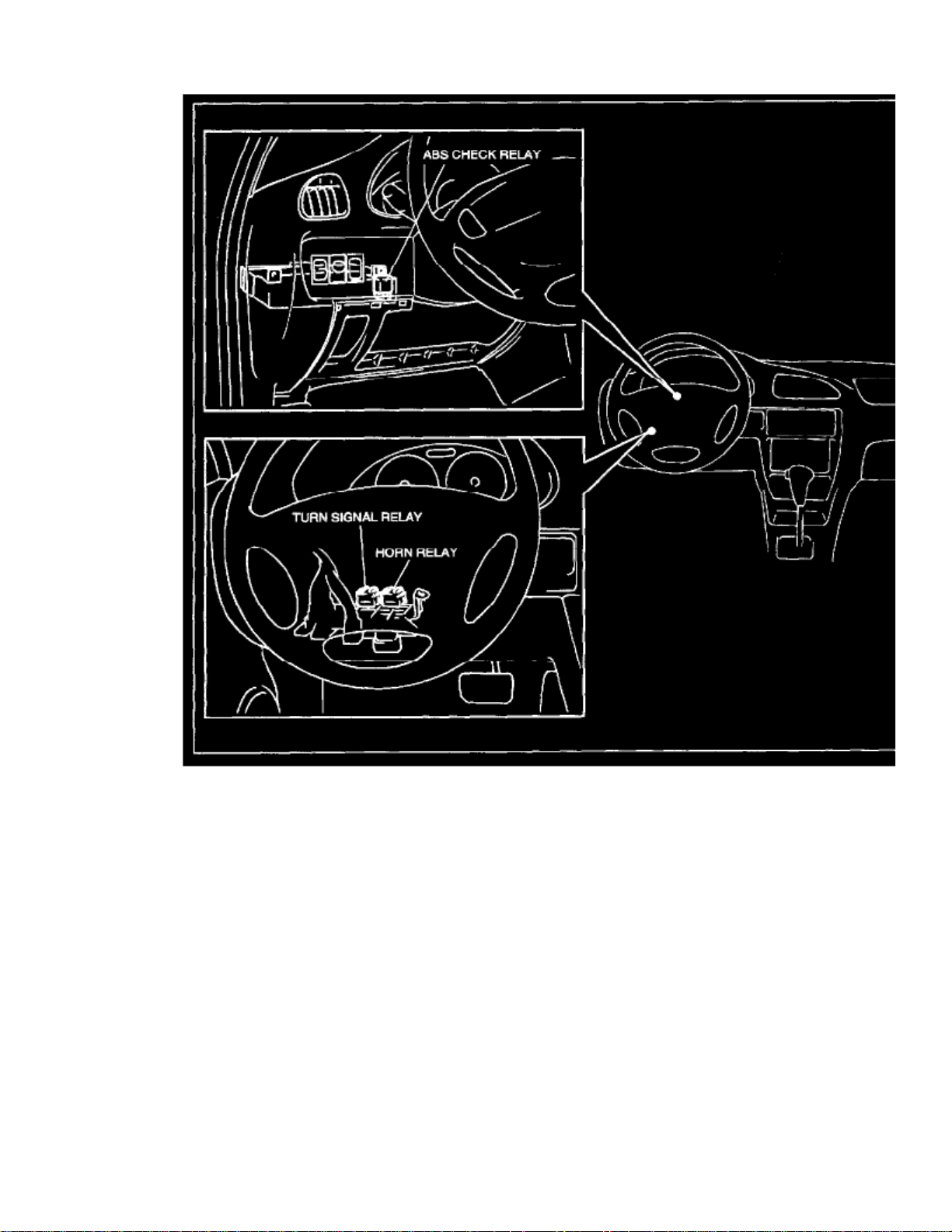
> Relays and Modules > Relays and Modules - Lighting and Horns > Horn Relay > Component Information > Locations
Instrument Panel
Page 67

Page 68

> Relays and Modules > Relays and Modules - Lighting and Horns > Turn Signal Relay > Component Information > Locations
Instrument Panel
Page 69

Page 70

> Relays and Modules > Relays and Modules - Powertrain Management > Relays and Modules - Computers and Control Systems > Engine Control Module > Component Information > Locations
Page 71

Instrument Panel
Page 72

> Relays and Modules > Relays and Modules - Powertrain Management > Relays and Modules - Computers and Control Systems > Engine Control Module > Component Information > Locations > Page 106
Engine Control Module: Diagrams
Page 73

> Relays and Modules > Relays and Modules - Powertrain Management > Relays and Modules - Computers and Control Systems > Engine Control Module > Component
Information > Locations > Page 107
Swift GA L4-1298cc 1.3L SOHC MFI (2001)
Page 74

Page 75

> Relays and Modules > Relays and Modules - Powertrain Management > Relays and Modules - Computers and Control Systems > Engine Control Module > Component
Information > Locations > Page 108
Swift GA L4-1298cc 1.3L SOHC MFI (2001)
Page 76

Page 77

> Relays and Modules > Relays and Modules - Powertrain Management > Relays and Modules - Computers and Control Systems > Engine Control Module > Component
Information > Locations > Page 109
Swift GA L4-1298cc 1.3L SOHC MFI (2001)
Page 78

Page 79

> Relays and Modules > Relays and Modules - Powertrain Management > Relays and Modules - Computers and Control Systems > Engine Control Module > Component
Information > Locations > Page 110
Swift GA L4-1298cc 1.3L SOHC MFI (2001)
Page 80

Page 81

Page 82

> Relays and Modules > Relays and Modules - Powertrain Management > Relays and Modules - Computers and Control Systems > Engine Control Module > Component Information > Locations > Page 111
Engine Control Module: Description and Operation
Engine Control Module (ECM), Powertrain Control Module (PCM)
ECM (PCM) is installed to the underside of the instrument panel at the passenger's seat side.
ECM (PCM) is a precision unit consisting of microcomputer, A/D (Analog/Digital) converter, I/O (Input/Output) unit, etc..
It is an essential part of the electronic control system, for its functions include not only such a major function as to control fuel injector, IAC valve, fuelpump relay, etc. but also on-board diagnostic system (self-diagnosis function) and fail-safe function as described.
Page 83

Page 84

> Relays and Modules > Relays and Modules - Powertrain Management > Relays and Modules - Computers and Control Systems > Engine Control Module > Component Information > Locations > Page 112
Engine Control Module: Testing and Inspection
Page 85

> Relays and Modules > Relays and Modules - Powertrain Management > Relays and Modules - Computers and Control Systems > Engine Control Module > Component
Information > Locations > Page 113
Swift GA L4-1298cc 1.3L SOHC MFI (2001)
Page 86

Page 87

> Relays and Modules > Relays and Modules - Powertrain Management > Relays and Modules - Computers and Control Systems > Engine Control Module > Component
Information > Locations > Page 114
Swift GA L4-1298cc 1.3L SOHC MFI (2001)
Page 88

Page 89

> Relays and Modules > Relays and Modules - Powertrain Management > Relays and Modules - Computers and Control Systems > Engine Control Module > Component
Information > Locations > Page 115
Swift GA L4-1298cc 1.3L SOHC MFI (2001)
Page 90

Page 91

> Relays and Modules > Relays and Modules - Powertrain Management > Relays and Modules - Computers and Control Systems > Engine Control Module > Component
Information > Locations > Page 116
Swift GA L4-1298cc 1.3L SOHC MFI (2001)
Page 92

Page 93

Page 94

> Relays and Modules > Relays and Modules - Powertrain Management > Relays and Modules - Computers and Control Systems > Engine Control Module > Component Information > Locations > Page 117
Engine Control Module: Service and Repair
ENGINE CONTROL MODULE (ECM), POWERTRAIN CONTROL MODULE (PCM)
As ECM (PCM) consists of precision parts, be careful not to expose it to excessive shock.CAUTION:
REMOVAL
1. Disconnect battery negative cable at battery.2. Disable air bag system, refer to DISABLING THE AIR BAG SYSTEM".3. Open glove box, then while pressing glove box stopper, pull out glove box from instrument panel.4. Remove ECM (PCM) from body after removing its bolts.5. Disconnect couplers from ECM (PCM) while releasing coupler lock.
INSTALLATION
1. Connect couplers to ECM (PCM) securely.2. Install ECM (PCM) to body.3. Install glove box.4. Connect battery negative cable at battery.
Page 95

Page 96

> Relays and Modules > Relays and Modules - Powertrain Management > Relays and Modules - Computers and Control Systems > Fuel Cut Control Unit > Component Information > Testing and Inspection
Fuel Cut Control Unit: Testing and Inspection
FUEL CUT OPERATION INSPECTION
NOTE: OFF
Before inspection, check to make sure that gear shift lever is in neutral position (with A/T model, selector lever In "P" range), A/C is andthat parking brake lever is pulled all the way up.
3,000 r/min
1. Warm up engine to normal operating temperature.2. While listening to sound of injector by using sound scope or such, increase engine speed to higher than .3. Check to make sure that sound to indicate operation of injector stops when throttle valve is closed instantly and it is heard again when engine
speed is reduced to less than about .2,500 r/min
Page 97

Page 98

> Relays and Modules > Relays and Modules - Powertrain Management > Relays and Modules - Computers and Control Systems > Main Relay (Computer/Fuel System) > Component Information > Locations
Engine Room
Page 99

Page 100

> Relays and Modules > Relays and Modules - Powertrain Management > Relays and Modules - Computers and Control Systems > Main Relay (Computer/Fuel System) > Component Information > Locations > Page 124
Main Relay (Computer/Fuel System): Testing and Inspection
MAIN RELAY
1. Disconnect negative cable at battery.2. Remove main relay from relay box.
3. Check resistance between each two terminals as in table. If check results are as specified, proceed to next operation check. If not, replace.
4. Check that there is continuity between terminals "A" and "B" when battery is connected to terminals "C" and "D".
 Loading...