

Page 1

D - ADJUSTMENTS
Article Text
1993 Suzuki Swift
For 111
Copyright © 1998 Mitchell Repair Information Company, LLC
ARTICLE BEGINNING
Thursday, April 08, 1999 09:26AM
1993 ENGINE PERFORMANCE
Suzuki of America Corp. On-Vehicle Adjustments
Suzuki; Samurai, Sidekick, Swift
ENGINE MECHANICAL
Before performing any on-vehicle adjustments to fuel or
ignition system, ensure engine mechanical condition is okay.
VALVE CLEARANCE
NOTE: Swift DOHC uses hydraulic lifters. No adjustments are
required.
Samurai & Sidekick
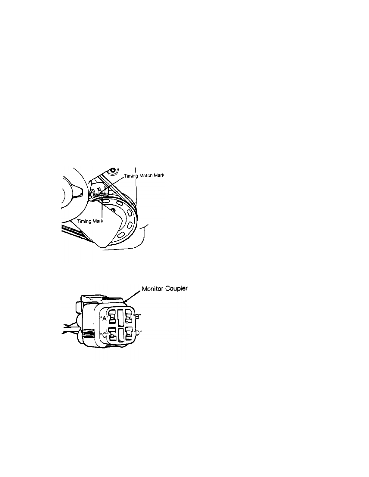
1) Remove valve cover. Rotate engine until zero degree (TDC)
timing mark of timing belt cover is in line with timing mark on
crankshaft pulley. See Fig. 1.
2) Ensure cylinder No. 1 is at TDC on compression stroke.
Remove distributor cap. On Samurai and Sidekick (TBI), ensure rotor is
pointed upward at distributor hold-down bolt and to No. 1 terminal of
distributor cap. On Sidekick (MPI), ensure rotor is at about 1 o’clock
position and pointed to No. 1 terminal of distributor cap. If rotor is
not as described, rotate crankshaft 360 degrees.
3) Measure valve clearance between adjustment screw and valve
stem using shim thickness gauge. Check intake valve clearance of
cylinders No. 1 and 2 and exhaust valve clearance of cylinders No.
1and 3. See VALVE CLEARANCE SPECIFICATIONS table.
4) Turn crankshaft one complete revolution (360 degrees).
Check intake valve clearance of cylinders No. 3 and 4 and exhaust
valve clearance of cylinders No. 2 and 4.
5) Adjust valves by loosening lock nut and turning adjusting
screw until clearance is as specified. After adjusting clearance,
tighten adjusting screw lock nut to 11.0-13.5 ft. lbs. (15-18 N.m) for
Samurai or 90-108 INCH lbs. (10-13 N.m) on Sidekick. On all models,
recheck clearance.
VALVE CLEARANCE SPECIFICATIONS TABLE
ДДДДДДДДДДДДДДДДДДДДДДДДДДДДДДДДДДДДДДДДДДДДДДДДДДДДДДДДДДДДДДДДДДДДДД
Application In. (mm)
Samurai, Sidekick (TBI) & Swift SOHC
Engine Cold
Intake ........................................ .005-.007 (.13-.18)
Exhaust ....................................... .006-.008 (.15-.20)
Engine Hot
Intake ........................................ .009-.011 (.23-.28)
Exhaust ....................................... .010-.012 (.25-.30)
Page 2

D - ADJUSTMENTS
Article Text (p. 2)
1993 Suzuki Swift
For 111
Copyright © 1998 Mitchell Repair Information Company, LLC
Thursday, April 08, 1999 09:26AM
Sidekick (MPI)
Engine Cold
Intake & Exhaust .............................. .003-.005 (.08-.12)
Engine Hot
Intake & Exhaust .............................. .005-.006 (.12-.16)
Swift DOHC ..................................................... (1)
(1) - Hydraulic valve lash adjusters are used and no adjustment is
required.
ДДДДДДДДДДДДДДДДДДДДДДДДДДДДДДДДДДДДДДДДДДДДДДДДДДДДДДДДДДДДДДДДДДДДДД
Swift SOHC
1) Remove valve cover. Remove right inner fender apron
extension to enable timing marks to be seen. Align crankshaft pulley
timing mark with TDC mark on timing belt cover. See Fig. 1.
2) Remove distributor cap. Ensure rotor is pointing upward
toward distributor hold-down bolt and to No. 1 terminal of distributor
cap. If rotor is not as described, rotate crankshaft 360 degrees.
3) Measure valve clearance between adjustment screw and valve
stem using shim thickness gauge. Check intake valve clearance of
cylinders No. 1 and 2 and exhaust valve clearance of cylinders No.
1and 3. See VALVE CLEARANCE SPECIFICATIONS table. Turn crankshaft one
complete revolution (360 degrees). Check intake valve clearance of
cylinders No. 3 and 4 and exhaust valve clearance of cylinders No. 2
and 4.
4) Adjust valves by loosening lock nut and turning adjusting
screw until clearance is as specified. Hold adjusting screw while
tightening lock nut to 11.0-13.5 ft. lbs. (15-18 N.m). Recheck
clearance.
IGNITION TIMING
NOTE: Verify that increasing engine speed advances ignition timing.
Samurai & Sidekick
1) Ensure transmission is in Neutral or Park and parking
brake is set. Inspect crankshaft pulley timing mark and timing mark
indicator on timing belt cover. See Fig. 1. Clean marks as required.
Start engine, and warm it to normal operating temperature. Turn engine
off with ignition on for 5 seconds. Restart engine. Run engine at 2000
RPM for 5 minutes, and then return it to idle. Turn all accessories
off. Attach timing light to No. 1 spark plug wire. Ensure idle speed
is correct. See IDLE SPEED SPECIFICATIONS table under IDLE SPEED &
MIXTURE.
CAUTION: Driving with jumper wire installed in monitor coupler will
damage catalytic converter.
2) Remove protective cap from monitor coupler located next to
battery. Connect jumper wire between terminals "C" (ground) and "D"
(test switch). See Fig. 2. Aim timing light at crankshaft pulley and
timing cover timing marks. If ignition timing is not within
Page 3
D - ADJUSTMENTS
Article Text (p. 3)
1993 Suzuki Swift
For 111
Copyright © 1998 Mitchell Repair Information Company, LLC
Thursday, April 08, 1999 09:26AM
specification, loosen distributor hold-down flange bolts, and rotate
distributor to obtain correct ignition timing. See IGNITION TIMING
table. Tighten distributor hold-down flange bolts, and recheck
ignition timing.
NOTE: With jumper wire installed, timing should be fixed. If
timing varies, terminal "D" is not properly grounded.
3) Remove jumper wire from monitor coupler. Ensure ignition
timing advances as engine speed increases. If ignition timing does not
advance, check TPS, monitor coupler wiring circuit, engine start
signal circuit and ECM.
Fig. 1: Locating Ignition Timing Mark
Courtesy of Suzuki of America Corp.
Fig. 2: Identifying Monitor Coupler Terminals (Samurai & Sidekick)
Courtesy of Suzuki of America Corp.
IGNITION TIMING TABLE (Degrees BTDC @ RPM) (1)
ДДДДДДДДДДДДДДДДДДДДДДДДДДДДДДДДДДДДДДДДДДДДДДДДДДДДДДДДДДДДДДДДДДДДДД
Application Man. Trans. Auto. Trans.
Samurai .................. (2) 7-9 @ 800 ................ Not Used
Sidekick
MPI ..................... (2) 4-6 @ 800 ........... (2) 4-6 @ 800
TBI ..................... (2) 7-9 @ 800 ........... (2) 7-9 @ 800
Swift
Page 4
D - ADJUSTMENTS
Article Text (p. 4)
1993 Suzuki Swift
For 111
Copyright © 1998 Mitchell Repair Information Company, LLC
Thursday, April 08, 1999 09:26AM
DOHC ................. (3) 5-7 @ 800-900 ..... (3) 5-7 @ 800-900
SOHC .................... (3) 4-6 @ 750 ........... (3) 4-6 @ 850
(1) - See Fig. 1 for timing mark location.
(2) - With jumper wire installed between "C" and "D" terminals of
monitor coupler connector, located near battery. See Fig. 2.
(3) - With jumper wire installed between "D" and "E" terminals of
monitor coupler connector, located near ignition coil.
See Fig. 3.
ДДДДДДДДДДДДДДДДДДДДДДДДДДДДДДДДДДДДДДДДДДДДДДДДДДДДДДДДДДДДДДДДДДДДДД
Swift
1) Ensure transmission is in Neutral or Park. Set parking
brake. Inspect crankshaft pulley timing mark and timing mark indicator
on timing belt cover. See Fig. 1. Clean marks as required. Start
engine, and warm it to normal operating temperature. Turn all
accessories off. Attach timing light to No. 1 spark plug wire. Ensure
idle speed is correct. See IDLE SPEED SPECIFICATIONS table under IDLE
SPEED & MIXTURE.
CAUTION: Driving with jumper wire installed in monitor coupler will
damage catalytic converter.
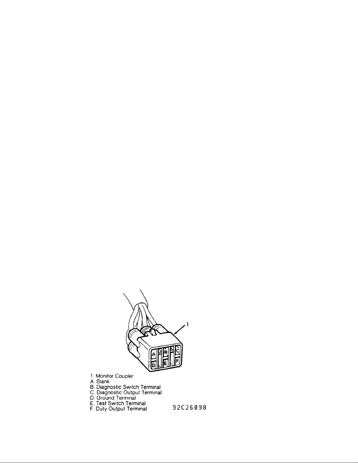
2) Connect terminals "D" (ground) and "E" (test switch) of
monitor coupler. See Fig. 3. Aim timing light at crankshaft pulley and
timing cover timing marks. If ignition timing is not within
specification, loosen distributor hold-down bolt and rotate
distributor to obtain correct ignition timing. See IGNITION TIMING
table. Tighten distributor hold-down bolt, and recheck ignition
timing.
Fig. 3: Identifying Monitor Coupler Terminals (Swift)
Courtesy of Suzuki of America Corp.
Page 5

D - ADJUSTMENTS
Article Text (p. 5)
1993 Suzuki Swift
For 111
Copyright © 1998 Mitchell Repair Information Company, LLC
PICK-UP COIL AIR GAP
Thursday, April 08, 1999 09:26AM
1) Remove distributor cap and rotor. Using non-magnetic shim
thickness gauge, measure air gap between reluctor tooth and pick-up
coil. See PICK-UP COIL AIR GAP table. If adjustment is required,
loosen pick-up coil plate hold-down screws.
2) Using blade screwdriver, move pick-up coil plate to adjust
air gap to specification. See PICK-UP COIL AIR GAP table. Tighten
screws, and recheck air gap. Ensure no metal particles are on pick-up
coil tooth.
PICK-UP COIL AIR GAP TABLE
ДДДДДДДДДДДДДДДДДДДДДДДДДДДДДДДДДДДДДДДДДДДДДДДДДДДДДДДДДДДДДДДДДДДДДД
Application In. (mm)
Samurai ........................................................ (1)
Sidekick ....................................................... (1)
Swift
DOHC (2) ...................................... .008-.012 (.20-.30)
SOHC ................................................... .008 (.20)
(1) - Not adjustable.
(2) - Also referred to as crank angle sensor air gap.
ДДДДДДДДДДДДДДДДДДДДДДДДДДДДДДДДДДДДДДДДДДДДДДДДДДДДДДДДДДДДДДДДДДДДДД
IDLE SPEED & MIXTURE
NOTE: Mixture is not adjustable. Mixture is controlled by ECM from
various sensor inputs.
COLD (FAST) IDLE
NOTE: Cold start or fast idle speed is not adjustable. Air valve
operation supplies by-pass air for cold starting.
IDLE SPEED
NOTE: DO NOT adjust idle speed in areas above 8200 ft. elevation.
Samurai
1) Start engine, and warm it to normal operating temperature.
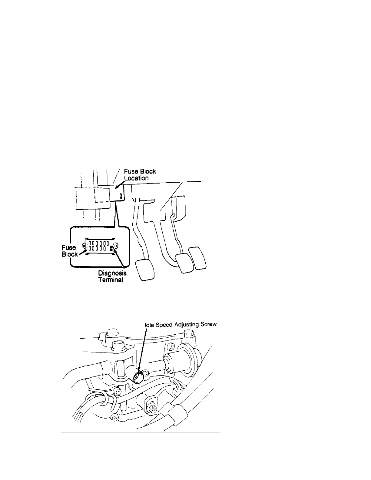
Install spare fuse into diagnosis terminal of fuse box, and ensure
Malfunction Indicator Light (MIL) indicates Code 12. See Fig. 4.
2) Turn engine off. Connect Duty Meter (99963-00006) to
monitor coupler duty check terminal "A" and ground terminal "C". See
Fig. 2. Test connector is located near battery. Turn ignition on, and
wait 5 seconds.
3) Start engine, run it at 2000 RPM for 5 minutes and then
return it to idle. Using duty meter, ensure idle speed and IAC duty
percentage are within specification. See IDLE SPEED SPECIFICATIONS and
IAC DUTY AT SPECIFIED IDLE SPEED tables. If idle speed and/or IAC duty
percentage require adjustment, remove idle speed adjusting screw
Page 6
D - ADJUSTMENTS
Article Text (p. 6)
1993 Suzuki Swift
For 111
Copyright © 1998 Mitchell Repair Information Company, LLC
Thursday, April 08, 1999 09:26AM
protective cap on throttle body. To adjust idle speed, turn adjusting
screw. See Fig. 5.
4) When idle speed and IAC duty percentage are within
specification and vehicle is equipped with A/C, go to step 5). If
vehicle is not equipped with A/C, reinstall idle speed adjusting screw
protective cap to throttle body. Remove duty meter from monitor
coupler, and rein-stall cap. Remove spare fuse from diagnosis terminal
of fuse box.
5) Turn A/C on, and set fan switch to LOW position. Check
idle speed and IAC duty percentage. If idle speed and/or IAC duty
percentage is not within specification, turn A/C VSV adjusting screw
to adjust idle. See Fig. 6.
Fig. 4: Installing Diagnosis Terminal Fuse (Samurai)
Courtesy of Suzuki of America Corp.
Fig. 5: Locating Idle Speed Adjusting Screw (Typical)
Courtesy of Suzuki of America Corp.
Page 7

D - ADJUSTMENTS
Article Text (p. 7)
1993 Suzuki Swift
For 111
Copyright © 1998 Mitchell Repair Information Company, LLC
Thursday, April 08, 1999 09:26AM
Fig. 6: Locating A/C VSV Adjusting Screw (Samurai & Sidekick)
Courtesy of Suzuki of America Corp.
IDLE SPEED SPECIFICATIONS TABLE (1)
ДДДДДДДДДДДДДДДДДДДДДДДДДДДДДДДДДДДДДДДДДДДДДДДДДДДДДДДДДДДДДДДДДДДДДД
Application Idle RPM
Samurai
With A/C Off .............................................. 750-850
With A/C On .......................................... (2) 950-1050
Sidekick
With A/C Off .............................................. 750-850
With A/C On .......................................... (3) 950-1050
Swift
DOHC
With A/C Off .............................................. 800-900
With A/C On ........................................... (2) 850-950
SOHC
With A/C Off
Auto. Transaxle .......................................... 800-900
Man. Transaxle ........................................... 700-800
With A/C On
Auto. Transaxle (4) .................................. (2) 800-900
Man. Transaxle (4) .................................... (2)700-800
Auto. & Man. Transaxles (5) .............................. 850-950
(1) - Transaxle or transmission in Neutral or Park.
(2) - A/C idle speed is adjusted by rotating adjusting screw on A/C
Vacuum Switching Valve (VSV).
(3) - With auto. transmission in gear, idle RPM is 750-850.
(4) - When ECM part number ends with "0".
(5) - When ECM part number ends with number other than "0".
ДДДДДДДДДДДДДДДДДДДДДДДДДДДДДДДДДДДДДДДДДДДДДДДДДДДДДДДДДДДДДДДДДДДДДД
IAC DUTY AT SPECIFIED IDLE SPEED TABLE (1)
ДДДДДДДДДДДДДДДДДДДДДДДДДДДДДДДДДДДДДДДДДДДДДДДДДДДДДДДДДДДДДДДДДДДДДД
Application Percent
Page 8

D - ADJUSTMENTS
Article Text (p. 8)
1993 Suzuki Swift
For 111
Copyright © 1998 Mitchell Repair Information Company, LLC
Thursday, April 08, 1999 09:26AM
Samurai & Sidekick .............................................. 50
Swift
DOHC ........................................................ 30-40
SOHC (2) .................................................... 25-35
(1) - See IDLE SPEED SPECIFICATIONS table.
(2) - With A/C turned off (if equipped).
ДДДДДДДДДДДДДДДДДДДДДДДДДДДДДДДДДДДДДДДДДДДДДДДДДДДДДДДДДДДДДДДДДДДДДД
Sidekick
1) Start engine, and warm it to operating temperature. Turn
all accessories off. Ensure all fuel and emission control system wire
connectors and hoses are properly connected. Ensure accelerator cable
has free play at throttle body. Ensure ignition timing is correct. See
IGNITION TIMING table under IGNITION TIMING. Ensure air cleaner and
ducts are properly installed and air filter element is in good
condition.
2) Connect service wire between terminals "B" (diagnosis
switch) and "C" (ground) of monitor coupler. See Fig. 2. Ensure MIL
(CHECK ENGINE light) indicates Code 12. Turn engine off, and connect
Duty Meter (99963-00006) to monitor coupler duty terminals "A"
(output) and "C" (ground). Test connector is located near battery.
Connect tachometer.
3) Start engine, and warm it to operating temperature. Ensure
idle speed and IAC duty percentage are within specification. See IDLE
SPEED SPECIFICATIONS and IAC DUTY AT SPECIFIED IDLE SPEED tables. If
idle speed and/or IAC duty percentage require adjustment, remove idle
speed adjusting screw protective cap on throttle body. Turn idle speed
adjusting screw to adjust idle to specification. See Fig. 5.
4) When idle speed and IAC duty percentage are as specified
and vehicle is equipped with A/C, go to next step. If vehicle is not
equipped with A/C, reinstall idle speed adjusting screw protective cap
to throttle body and remove service jumper wire. Remove duty meter
from monitor coupler, and reinstall cap.
5) Turn A/C on, and set fan switch to LOW position. Check
idle speed and IAC duty percentage with A/C on. If idle speed and IAC
duty percentage are not as specified, turn A/C VSV adjusting screw to
adjust idle to specification. See Fig. 6.
NOTE: On Swift, specified values used for this inspection and
adjustment vary depending on type of ECM. Type of ECM can be
identified by last digit of ECM part number. Last digit will
be "0" or a number other than "0".
Swift SOHC
1) Idle speed is controlled by ECM using IAC valve and
requires no adjustments under normal conditions. If conditions require
idle speed to be adjusted, start engine and warm it to operating
temperature. Turn all accessories off. Ensure all fuel and emission
control system wire connectors and hoses are properly connected.
Ensure accelerator cable has free-play, air cleaner and ducts are
properly installed and air filter element is in good condition.
Page 9

D - ADJUSTMENTS
Article Text (p. 9)
1993 Suzuki Swift
For 111
Copyright © 1998 Mitchell Repair Information Company, LLC
Thursday, April 08, 1999 09:26AM
2) Ensure ignition timing is correct. See IGNITION TIMING
table under IGNITION TIMING. Connect terminal "B" (diagnosis switch)
to terminal "D" (ground) using a service wire. See Fig. 3. MIL (CHECK
ENGINE light) should indicate Code 12. Attach duty meter to duty
output terminal "F" and ground terminal "D". Remove idle speed
adjusting screw cap from side of throttle body, just above throttle
lever. Turn idle speed adjusting screw to obtain correct idle speed.
See IDLE SPEED SPECIFICATIONS and IAC DUTY AT SPECIFIED IDLE SPEED
tables. On vehicles without A/C, remove service wire, reinstall
protective cap to throttle body and recheck idle speed.
3) On vehicles equipped with A/C, turn A/C switch to ON
position and set fan switch to HIGH position. With A/C operating
correctly, verify idle speed is 850-950 RPM. If adjustment is
required, turn A/C Vacuum Switching Valve (VSV) adjusting screw as
necessary. See Fig. 7. See IDLE SPEED SPECIFICATIONS table. Remove
service wire, reinstall protective cap to throttle body and recheck
idle speed.
Fig. 7: Identifying Typical Idle Adjustment System (Swift)
Courtesy of Suzuki of America Corp.
Swift DOHC
1) Idle speed is controlled by IAC valve and should not
require adjustment. If idle speed needs to be changed, start engine
and warm it to operating temperature. Turn all accessories off. Ensure
all fuel and emission control system wire connectors and hoses are
properly connected. Ensure accelerator cable has free play. Ensure air
cleaner and ducts are properly installed and air filter element is in
good condition.
2) Ensure ignition timing is correct. See IGNITION TIMING
Page 10

D - ADJUSTMENTS
Article Text (p. 10)
1993 Suzuki Swift
For 111
Copyright © 1998 Mitchell Repair Information Company, LLC
Thursday, April 08, 1999 09:26AM
table under IGNITION TIMING. Connect terminal "B" (diagnosis switch)
to terminal "D" (ground) using a service wire. See Fig. 3. MIL (CHECK
ENGINE light) should indicate Code 12. Attach duty meter to duty
output terminal "F" and ground terminal "D". Remove idle speed
adjusting screw protective cap from top of throttle body. See Fig. 7.
Turn idle speed adjusting screw to obtain correct idle RPM. See IDLE
SPEED SPECIFICATIONS and IAC DUTY AT SPECIFIED IDLE SPEED tables.
3) On vehicles equipped with A/C, turn A/C switch to ON
position and set fan switch to HIGH position. With A/C operating
correctly, verify idle is 850-950 RPM and IAC duty is 30-40 percent.
If adjustment is required, turn A/C Vacuum Switching Valve (VSV)
adjusting screw to obtain correct idle. See IDLE SPEED SPECIFICATIONS
table. Remove service wire, reinstall protective cap to throttle body
and recheck idle speed.
THROTTLE CABLE
Samurai
1) Ensure throttle cable has 0.4-0.6" (10-15 mm) free play.
Hold exposed portion of cable at center and move cable up and down to
measure play. Use lock nut and adjusting nut on cable bracket to
adjust free play. See Fig. 8.
2) If throttle opener rod is pushed back by hand (i.e.,
throttle valve is at idle position), cable free play should be 0.12-0.
20" (3.0-5.0 mm). Use lock nut and adjusting nut on cable bracket to
adjust free play.
Fig. 8: Adj. Typical Acc. Cable Play (Samurai, Sidekick TBI & Swift)
Courtesy of Suzuki of America Corp.
Sidekick (MPI)
1) With throttle valve closed, accelerator pedal play should
be 0.08-0.27" (2.0-7.0 mm). Use lock nut and adjusting nut on cable
bracket to adjust free play. See Fig. 9.
2) With accelerator pedal depressed fully, check clearance
between throttle lever and lever stopper at throttle body. If
clearance is not 0.02-0.07" (0.5-2.0 mm), correct by changing height
of pedal stopper bolt located under accelerator pedal. After throttle
cable adjustment is complete, adjust transmission kickdown cable.
3) Check A/T cable free play. See Fig. 9. If clearance is not
0.03-0.06" (0.8-1.5 mm), use lock nut and adjusting nut on cable
Page 11

Copyright © 1998 Mitchell Repair Information Company, LLC
bracket to adjust free play.
D - ADJUSTMENTS
Article Text (p. 11)
1993 Suzuki Swift
For 111
Thursday, April 08, 1999 09:26AM
Fig. 9: Adjusting Cable Play (Sidekick MPI)
Courtesy of Suzuki of America Corp.
Sidekick (TBI)
1) Ensure cable has 0.4-0.6" (10-15 mm) free play. Hold
exposed portion of cable at center and move cable up and down to
adjust free play. See Fig. 8.
2) After throttle cable adjustment is complete, adjust
transmission kickdown cable. Loosen and back off kickdown lock nut and
adjusting nut considerably. With accelerator pedal fully depressed,
pull on kickdown cable housing to remove cable free play. With free
play removed, ensure clearance between kickdown cable bracket and
upper lock nut is 0.039" (1.00 mm). Adjust upper lock nut as
necessary.
3) Holding upper lock nut position on kickdown cable, release
accelerator pedal. While holding upper lock nut position, securely
tighten lower adjusting nut to bracket.
Swift
Ensure cable has .12-.20" (3.0-5.0 mm) free play. Hold
exposed portion of cable at center and move cable up and down to
measure free play. Use lock nut and adjusting nut on cable bracket to
adjust free play. See Fig. 8.
DASHPOT
Page 12

D - ADJUSTMENTS
Article Text (p. 12)
1993 Suzuki Swift
For 111
Copyright © 1998 Mitchell Repair Information Company, LLC
Thursday, April 08, 1999 09:26AM
Swift DOHC
1) Ensure transmission is in Park or Neutral and parking
brake is set. Start engine, and warm it to operating temperature. Turn
all accessories off. Ensure idle speed is within specification. See
IDLE SPEED SPECIFICATIONS table under IDLE SPEED.
2) Operate throttle lever to increase and decrease engine RPM
while noting RPM at which dashpot rod contacts throttle lever. Adjust
dashpot adjusting screw to specified RPM at which dashpot rod should
contact throttle lever. See Figs. 8 and 13. See DASHPOT ADJUSTMENT
table.
DASHPOT ADJUSTMENT TABLE
ДДДДДДДДДДДДДДДДДДДДДДДДДДДДДДДДДДДДДДДДДДДДДДДДДДДДДДДДДДДДДДДДДДДДДД
Application (1) RPM
Swift DOHC ............................................... 3000-3400
(1) - Engine speed when throttle lever contacts dashpot rod after
deceleration.
ДДДДДДДДДДДДДДДДДДДДДДДДДДДДДДДДДДДДДДДДДДДДДДДДДДДДДДДДДДДДДДДДДДДДДД
THROTTLE OPENER
Samurai
1) Ensure transmission is in Neutral or Park. Set parking
brake. Turn ignition on for 5 seconds, and then start engine. Run
engine at 2000 RPM for 5 minutes to warm it to operating temperature.
Return engine to idle speed. Turn all accessories off. Disconnect and
plug vacuum hose from throttle opener on throttle body.
2) Engine speed should increase to 2150-2250 RPM when vacuum
hose is removed from throttle opener. If engine speed is not within
specification, adjust by turning throttle opener adjusting screw. See
Fig. 10. Reconnect vacuum hose when adjustment is within
specification. See THROTTLE OPENER SPECIFICATIONS table.
Sidekick (TBI)
1) Ensure transmission is in Neutral or Park, and set parking
brake. Warm engine to operating temperature. Turn all accessories off.
Disconnect and plug vacuum hose from throttle opener on throttle body.
2) Engine speed should increase to 2100-2300 RPM when vacuum
hose is removed from throttle opener. If engine speed is not within
specification, adjust by turning throttle opener adjusting screw. See
Fig. 10. Reconnect vacuum hose when adjustment is within
specification. See THROTTLE OPENER SPECIFICATIONS table.
THROTTLE OPENER SPECIFICATIONS TABLE
ДДДДДДДДДДДДДДДДДДДДДДДДДДДДДДДДДДДДДДДДДДДДДДДДДДДДДДДДДДДДДДДДДДДДДД
Application (1) RPM
Samurai .................................................. 2150-2250
Sidekick TBI ............................................. 2100-2300
Page 13

D - ADJUSTMENTS
Article Text (p. 13)
1993 Suzuki Swift
For 111
Copyright © 1998 Mitchell Repair Information Company, LLC
Thursday, April 08, 1999 09:26AM
(1) - Transaxle or transmission in Neutral or Park with vacuum hose
disconnected and plugged at throttle opener.
ДДДДДДДДДДДДДДДДДДДДДДДДДДДДДДДДДДДДДДДДДДДДДДДДДДДДДДДДДДДДДДДДДДДДДД
Fig. 10: Adjusting Throttle Opener (Samurai & Sidekick TBI)
Courtesy of Suzuki of America Corp.
THROTTLE POSITION SENSOR (TPS)
THROTTLE POSITION SENSOR (TPS) RESISTANCE TABLE
ДДДДДДДДДДДДДДДДДДДДДДДДДДДДДДДДДДДДДДДДДДДДДДДДДДДДДДДДДДДДДДДДДДДДДД
Application Ohms
Samurai
Between Terminals "C" & "D"
With .008" (.20 mm) Clearance At Stop Screw ................. 0-550
With .016" (.41 mm) Clearance At Stop Screw .............. Infinity
Between Terminals "A" & "D" ............................. 3500-6500
Between Terminals "B" & "D"
At Idle (1) ................................................ 0-2000
At Wide Open Throttle ............................... (2) 2000-6500
Sidekick (MPI)
Between Terminals "A" & "B"
With .020" (.50 mm) Clearance At Stop Screw ................. 0-500
With .031" (.80 mm) Clearance At Stop Screw .............. Infinity
Between Terminals "A" & "D" ............................. 3500-6500
Between Terminals "A" & "C"
At Idle .................................................. 300-2000
At Wide Open Throttle ............................... (3) 2000-6500
Sidekick (TBI)
Between Terminals "C" & "D"
With .012" (.3 mm) Clearance At Stop Screw .................. 0-500
With .020" (.5 mm) Clearance At Stop Screw ............... Infinity
Between Terminals "A" & "D" ............................. 3500-6500
Page 14

D - ADJUSTMENTS
Article Text (p. 14)
1993 Suzuki Swift
For 111
Copyright © 1998 Mitchell Repair Information Company, LLC
Thursday, April 08, 1999 09:26AM
Between Terminals "B" & "D"
At Idle .............................................. (1) 300-2000
At Wide Open Throttle ............................... (2) 2000-6500
Swift (DOHC)
Between Terminals "C" & "D"
With .012" (.30 mm) Clearance At Stop Screw ................. 0-500
With .035" (.89 mm) Clearance At Stop Screw .............. Infinity
Between Terminals "C" & "A" ............................. 3500-6500
Between Terminals "C" & "B"
At Idle .................................................... 0-2000
At Wide Open Throttle ................................... 3500-6500
Swift (SOHC)
Between Terminals "A" & "B"
With .012" (.30 mm) Clearance At Stop Screw ........ Less Than 5000
With .035" (.89 mm) Clearance At Stop Screw .............. Infinity
Between Terminals "A" & "D" ............................. 4370-8130
Between Terminals "A" & "C"
At Idle .................................................. 240-1140
At Wide Open Throttle ................................... 3170-6600
(1) - To obtain idle position, apply 19 in. Hg vacuum to throttle
opener.
(2) - There should be more than 2000 ohms difference between idle and
wide open throttle resistance.
ДДДДДДДДДДДДДДДДДДДДДДДДДДДДДДДДДДДДДДДДДДДДДДДДДДДДДДДДДДДДДДДДДДДДДД
CAUTION: DO NOT rotate Samurai throttle stop screw to adjust idle.
Throttle stop screw is factory-set, and is used as zero
reference point for all other adjustments.
TPS Inspection (Samurai)
1) Disconnect TPS connector. Using hand vacuum pump, apply 20
in. Hg vacuum to throttle opener to move throttle lever to idle
position. Using ohmmeter, check resistance between upper and lower
terminals of TPS connector with proper shim thickness gauge inserted
between throttle valve lever and stop screw. See Fig. 10. See THROTTLE
POSITION SENSOR (TPS) RESISTANCE table.
2) If TPS inspection results are not within specification,
adjust TPS. Replace TPS if it cannot be adjusted to specification.
TPS Adjustment (Samurai)
1) Disconnect TPS harness connector and throttle opener
vacuum hose. Using hand vacuum pump, apply 20 in. Hg vacuum to
throttle opener to move throttle lever to idle position. Insert .012"
(.30 mm) shim thickness gauge between throttle lever and throttle stop
screw. See Fig. 10.
2) Connect ohmmeter between terminals "C" and "D" of TPS
connector. See Fig. 11. Loosen TPS mounting bolts, and turn TPS fully
clockwise. Turn TPS counterclockwise slowly to find position ohmmeter
reading changes from infinity to zero ohms. Tighten TPS mounting bolts
at that position.
Page 15

D - ADJUSTMENTS
Article Text (p. 15)
1993 Suzuki Swift
For 111
Copyright © 1998 Mitchell Repair Information Company, LLC
Thursday, April 08, 1999 09:26AM
Fig. 11: Throttle Pos. Sensor (TPS) Term. ID (Samurai & Sidekick TBI)
Courtesy of Suzuki of America Corp.
3) Ensure continuity does not exist between terminals "C" and
"D" when .016" (0.40 mm) shim thickness gauge is inserted between
throttle lever and throttle stop screw.
4) Ensure continuity exists between terminals "C" and "D"
when .008" (0.20 mm) shim thickness gauge is inserted between throttle
lever and throttle stop screw.
5) If continuity is not as specified in steps 3) and 4), TPS
zero adjustment is incorrect. Start adjustment sequence again. If
results are the same after readjusting, replace TPS. After final
adjustment is completed, reconnect TPS connector and vacuum hose to
throttle opener.
TPS Inspection (Sidekick MPI)
Disconnect negative battery cable. Unplug TPS connector.
Using ohmmeter, check resistance between terminals of TPS connector.
See Fig. 15. If idle switch check is not within specification, adjust
TPS installation angle. See THROTTLE POSITION SENSOR (TPS) RESISTANCE
table. Replace TPS if it cannot be adjusted to specification.
TPS Adjustment (Sidekick MPI)
1) Disconnect negative battery cable. Unplug TPS connector,
and insert .026" (0.65 mm) shim thickness gauge between throttle lever
and throttle stop screw. Loosen TPS mounting screws. Connect ohmmeter
between TPS terminals "A" and "B", and check resistance. See THROTTLE
POSITION SENSOR (TPS) RESISTANCE table.
2) Turn TPS fully counterclockwise, and then turn it
clockwise slowly to locate point where ohmmeter reading changes from
zero to infinity. Holding TPS at that position, tighten TPS mounting
screws snug.
3) Ensure continuity does not exist between terminals "A" and
"B" when 0.037" (0.8 mm) shim thickness gauge is inserted between
throttle lever and throttle stop screw. See Figs. 14 and 15.
4) Ensure continuity exists between terminals "A" and "B"
when 0.020" (0.5 mm) shim thickness gauge is inserted between throttle
lever and throttle stop screw. Tighten TPS mounting screws to 22.8-38.
4 INCH lbs. (2.5-4.5 N.m).
Page 16

D - ADJUSTMENTS
Article Text (p. 16)
1993 Suzuki Swift
For 111
Copyright © 1998 Mitchell Repair Information Company, LLC
Thursday, April 08, 1999 09:26AM
5) If continuity is not as specified in steps 3) and 4), TPS
zero adjustment is incorrect. Start adjustment sequence again. If
results are the same after readjusting, replace TPS. After final
adjustment is completed, reconnect TPS connector.
TPS Inspection (Sidekick TBI)
Disconnect negative battery cable. Disconnect TPS harness
connector. Using ohmmeter, check resistance between each pair of
terminals. See Fig. 11. See THROTTLE POSITION SENSOR (TPS) RESISTANCE
table. If resistances are not as specified, adjust TPS. Recheck
resistance between each pair of terminals. If TPS cannot be adjusted
to obtain correct values, replace TPS.
TPS Adjustment (Sidekick TBI)
1) Disconnect TPS harness connector and throttle opener
vacuum hose. Using hand vacuum pump, apply 19 in. Hg vacuum to
throttle opener to move throttle lever to idle position. Counting
number of turns, loosen idle speed adjusting screw until clearance is
obtained between throttle lever and adjusting screw. Record number of
turns. Connect ohmmeter between terminals "C" and "D". See Fig. 11.
2) Insert .016" (.40 mm) thickness gauge between idle speed
adjusting screw and throttle lever. Loosen TPS mounting screws. Turn
TPS fully clockwise. Slowly rotate TPS counterclockwise to locate
position where ohmmeter readings changes from infinity to zero ohms.
Holding TPS at this position, tighten mounting screws to 30 INCH lbs.
(3.4 N.m.). Repeat TPS INSPECTION (SIDEKICK TBI) to verify correct
adjustment and operation.
3) After verifying adjustment, reconnect TPS harness
connector and throttle opener vacuum hose. Turn idle speed adjusting
screw inward number of turns previously recorded. If necessary,
readjust idle speed. See IDLE SPEED.
CAUTION: DO NOT adjust Swift DOHC throttle stop screw to adjust
idle. Throttle stop screw is factory-set, and is used as
zero reference point for all other adjustments.
TPS Inspection (Swift DOHC)
Unplug TPS connector. Using ohmmeter, check resistance with
selected shim thickness gauges between throttle stop screw and
throttle lever. See Figs. 12 and 13. See THROTTLE POSITION SENSOR
(TPS) RESISTANCE table. If TPS cannot be adjusted to obtain correct
values at terminals "C" and "D", replace TPS.
Page 17

D - ADJUSTMENTS
Article Text (p. 17)
1993 Suzuki Swift
For 111
Copyright © 1998 Mitchell Repair Information Company, LLC
Thursday, April 08, 1999 09:26AM
Fig. 12: Throttle Position Sensor (TPS) Terminal ID (Swift DOHC)
Courtesy of Suzuki of America Corp.
Fig. 13: Inserting Shim Thickness Gauge (Swift DOHC)
Courtesy of Suzuki of America Corp.
TPS Adjustment (Swift DOHC)
1) Unplug TPS connector, and loosen TPS mounting screws.
Place a .025" (.63 mm) shim thickness gauge between throttle lever and
throttle stop screw. See Fig. 13.
2) Connect ohmmeter between terminals "C" and "D". See
Fig. 12. Turn TPS fully clockwise, and then slowly rotate TPS
counterclockwise to locate position at which ohmmeter reading changes
from zero to infinity. Holding TPS at that position, tighten mounting
screws snug.
3) Ensure continuity does not exist between terminals "C" and
"D" when 0.035" (0.90 mm) shim thickness gauge is inserted between
throttle lever and throttle stop screw.
4) Ensure continuity exists between terminals "C" and "D"
when 0.012" (0.30 mm) shim thickness gauge is inserted between
throttle lever and throttle stop screw. Tighten TPS mounting screws to
Page 18

D - ADJUSTMENTS
Article Text (p. 18)
1993 Suzuki Swift
For 111
Copyright © 1998 Mitchell Repair Information Company, LLC
Thursday, April 08, 1999 09:26AM
30 INCH lbs.(3.4 N.m).
5) If continuity is not as specified in steps 3) and 4), TPS
zero adjustment is incorrect. Start adjustment sequence again. If
results are the same after readjusting, replace TPS. After final
adjustment is completed, reconnect TPS connector.
CAUTION: DO NOT adjust Swift SOHC throttle stop screw to adjust
idle. Throttle stop screw is factory-set, and is used as
zero reference point for all other adjustments.
TPS Inspection (Swift SOHC)
Unplug TPS connector. Using ohmmeter, check resistance
between terminals of TPS connector with proper shim thickness gauge
inserted between throttle lever and throttle stop screw. See Figs. 14
and 15. See THROTTLE POSITION SENSOR (TPS) RESISTANCE table.
Fig. 14: Inserting Shim Thickness Gauge (Sidekick MPI & Swift SOHC)
Courtesy of Suzuki of America Corp.
Fig. 15: Throttle Position Sensor (TPS) Term. ID (Swift SOHC
Shown; Sidekick MPI Is Similar)
Courtesy of Suzuki of America Corp.
Page 19

D - ADJUSTMENTS
Article Text (p. 19)
1993 Suzuki Swift
For 111
Copyright © 1998 Mitchell Repair Information Company, LLC
Thursday, April 08, 1999 09:26AM
TPS Adjustment (Swift SOHC)
1) Unplug TPS connector, and loosen TPS mounting screws.
Insert .024" (.60 mm) shim thickness gauge between throttle lever and
throttle stop screw. Connect ohmmeter between TPS terminals "A" and
"B". See Fig. 15.
2) Turn TPS fully counterclockwise. Turn TPS clockwise to
locate position ohmmeter reading changes from zero to infinity.
Holding TPS at that position, tighten TPS mounting screws snug.
3) Ensure continuity does not exist between terminals "A" and
"B" when 0.035" (0.90 mm) shim thickness gauge is inserted between
throttle lever and throttle stop screw.
4) Ensure continuity exists between terminals "A" and "B"
when 0.012" (0.30 mm) shim thickness gauge is inserted between
throttle lever and throttle stop screw. Tighten TPS mounting screws to
18 INCH lbs.(2.0 N.m).
5) If continuity is not as specified in steps 3) and 4), TPS
zero adjustment is incorrect. Start adjustment sequence again. If
results are the same after readjusting, replace TPS. After final
adjustment is completed, reconnect TPS connector.
POWER STEERING VSV
Disconnect VSV connector, and check resistance between
terminals. If resistance is not 33-39 ohms, replace VSV. If resistance
is 33-39 ohms, disconnect vacuum hoses from 3-way joints. Blow into
top hose. Air should not come out of other hose. With 12 volts and
ground applied to terminals, blow into top hose. Air should pass
through hoses. If results are not as described, replace VSV.
END OF ARTICLE
 Loading...