

Page 1
USETHE
SV1
OOOWSVIOQO
MANUAL
WITH:
SERVICE MANUAL
(99500-39251
-WE)
Page 2
0
This
manual
fer
from
NOTE
*
Any
('05-model)
"
Please
manual
describes
those
of
the
differences
Sn
refer
to
.
sewice
SV7
between
specifications
the
SVlOOOK4/SK4
&fa.
OOOK4/SK4
FOREWORD
sewice
('04.model) .
the
and
service
specifications
SVIOOOK4JSK4
data
are
indicated
Senrice
Manual
for
and
sewicing
('04-model)
with
details
which
procedures
and
an
asterisk
a=
which
M-
SVIOOOKS/SK5
mark
(y
.
nof
given
in
this
G0UlVTRYANDARE.A
SPEC!F/CAfSONS(SVl000K5)
SPECIFICATIONS
SERVICE
SERVICE
CRANKCASE-CRA
Fi
SYSTEM
ECM
ECM
FAlLmSAFE
MALFUNCTION
FI
SYSTEM
FRONT
FUEL
WIRING
THROmLE
THROTTLE BODY
REAR
REAR
DATA
DATA
TERIMtNA
TERMINAL
FORK
LEVEL
HA
BRAKE
BRAKE HOSE ROUTIPJG
(SVlOOOK5)
(SVf
WRING
L
(Fur
{For
FUNCnON....
CODE AND DEFECTIVE
TROUBL
(For
INDECA
RNESS
CABLE
HOSE
CODES
(SVlOOOSK5)~m~mm~m~~m~m~m-~~-~~sm~m~mm~~mmmmmmm
...................
WSKS)
NKSHA
DIAGRAM
ESHOOJING
SVf
ROUTlNG
ROWSNG
IMSTALLAflOWOSE
FT
K4-Model)
KWodeF)
............................................................................
000SK5)
TOR
SWITCH
ROUTING
.......................................................................
...........................
.....................................................
,.
-
............
BEARING
.......................................................
SEL EG770
......................................................
..........,,...,.......,,........*..*......
r..l
hl
...............
...
.................
,
............
.......................................................................
..................
...,
................................................
CONDITION
..........
,
..,
.....
,.
..........
.....................................................................
......................................................................
INSPECTION
(For
SVIOOOK5)
(For
SVICWOK5)
(For
SV I OOOK5)
(For
SVIUOOSK5)
ROCrSING
~~.mm~mm.~.~m~pm~~~m~~m~sm~m~~mm~m~m~37
...............................a*..
........
............................................
.....
.............................
.............................................
........................................
2
3
5
7
16
=25
26
27
28
m......29
30
32
36
38
,.40
41
42
43
b
CT)PVRIEHT
9.1
171
1KI
hAMnB
t'r7OOnPA+fnhl
mn.4
StOZWKl
MOTOR
CORPORATION
Page 3
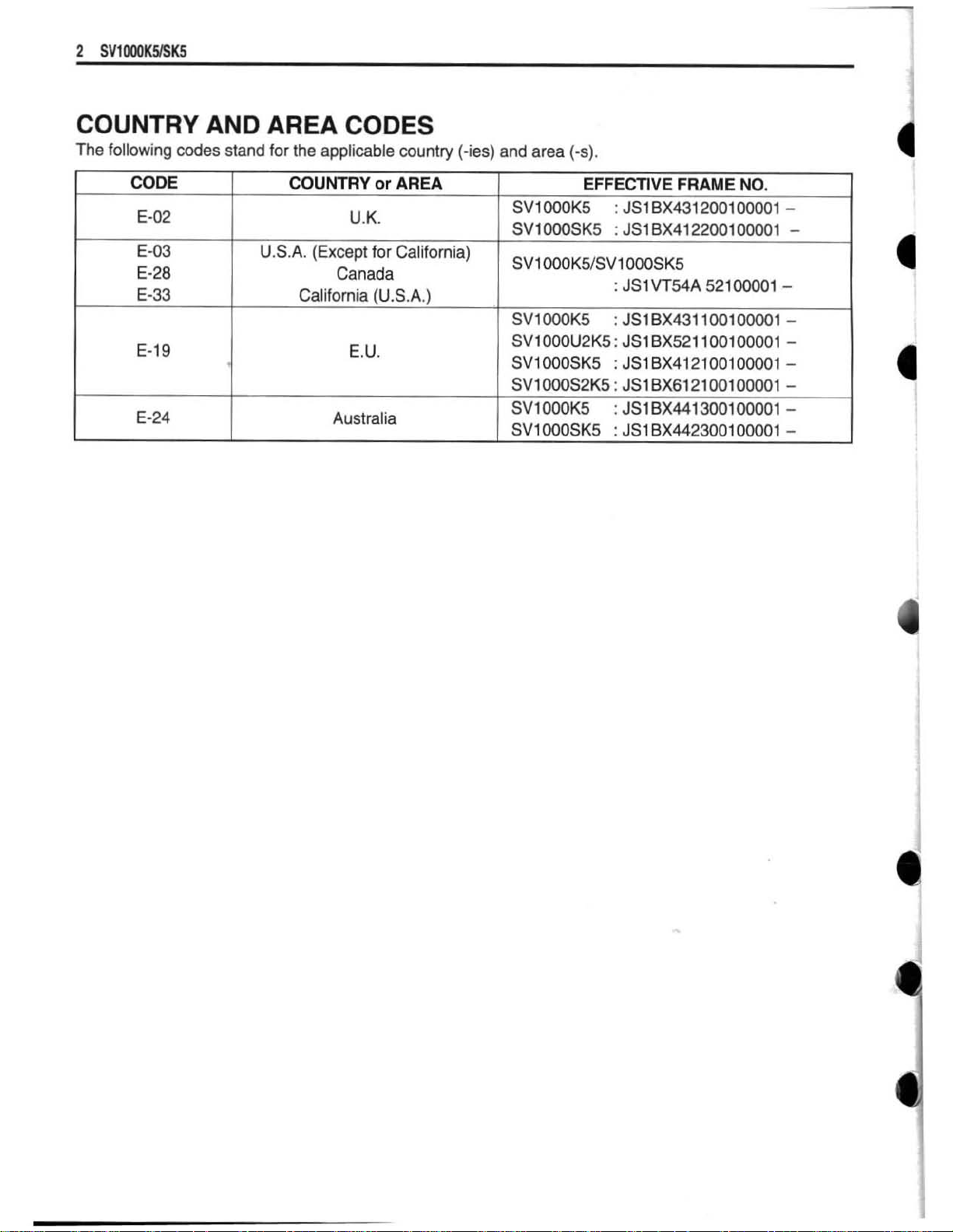
COUNTRY
The
following
codes
AND
stand
AREA
for
the
applicable
CODES
country
(-ies)
and
area
(-s).
CODE
E-02
E-03
E-28
E-33
E-19
E-24
COUNTRY
USA.
California
U.K.
(Except
Canada
E.U.
Australia
or
AREA
-i
for
California)
(U.S.A.)
EFFECTIVE
SV1
OMSK5
SV1
OOOKS,SV1
SV1
WOK5
SV1000U2K5
SV1000SK5
SV?
000S2K5
SV1
OOOK5
SV1000SK5
FRAME
:
JS1
BX412200100001
000SK5
:
JSIVT54A
:
JS
18x431
:
JSIBX521100100001
:
JS1BX412100100001-
:
3S1BX612100100001
:
3ST
BX441300100001
:
JS1
BX442300100001
NO,
200
1
0000
52100001
1001
00001
1
-
-
-
-
-
-
-
-
Page 4
&d
-
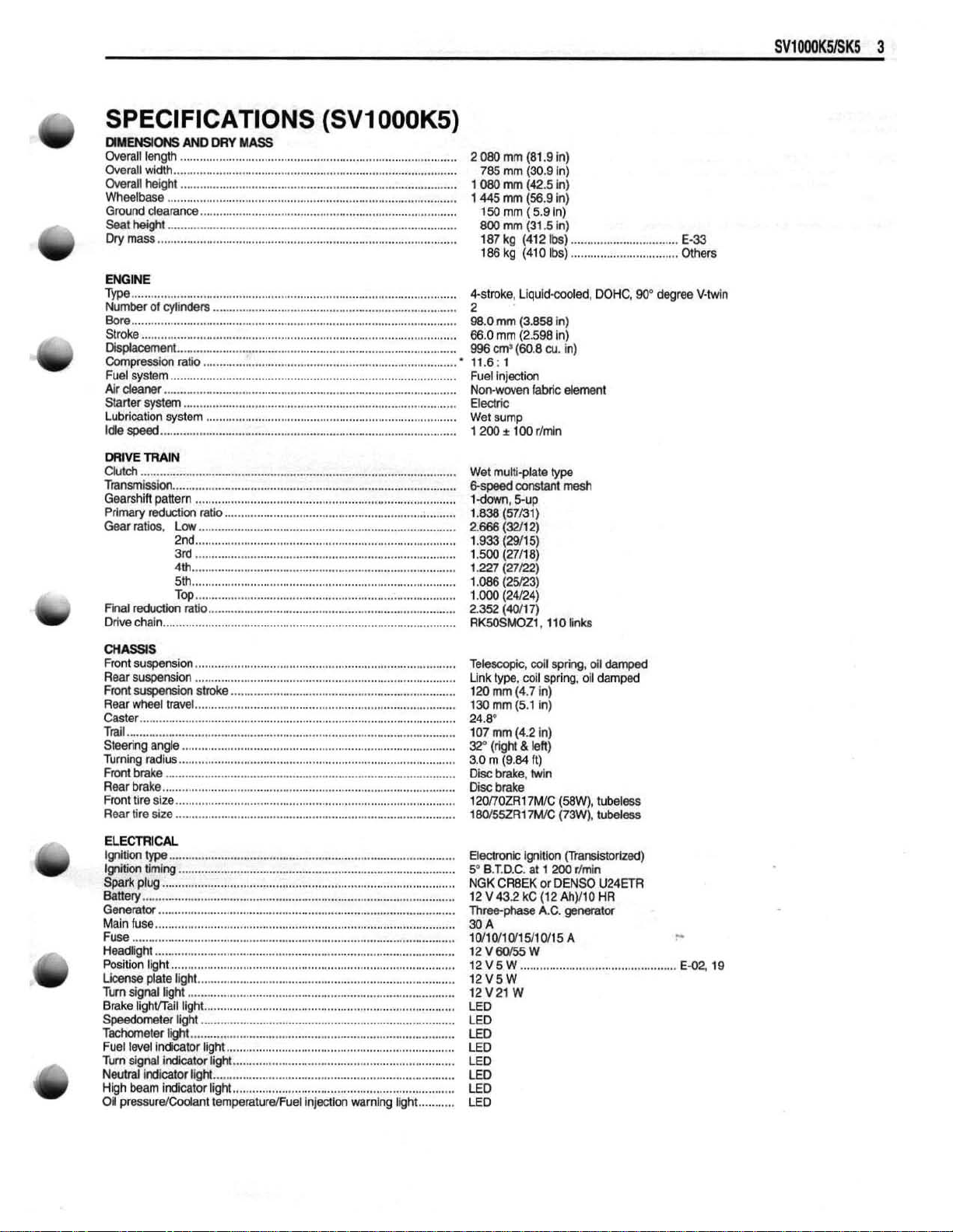
SPEClFlCATlONS
DM--
Overall
Overall
Overall
Wheelbase
Ground
Seat
height
Dry
mass
Type
....................
Number
Bare
.........................................................
Stroke
Displacement
Compression
Fuel system
Air
deaner
Starler
Lubricat~on
Idle
speed
Clutch
Transmis5im
Gearshift
Primary
Gear
ratim.
Final
raduetiwl
Dh
chafn
AND
OAY
length
.......................
....................................................................................
width
hergM
.....................................................................................
MASS
..
........................................................
........................................................................................
clearance
..........
...
..........................................................
.........................................................................................
...........................
of
eylindelg
.................................................................................................
..
..........................................................
..
........................................................................
...........................................................................
...................................................................................
ratio
............................
........................................................................................
..........................................................................................
system
...............................................................................
system
.....................
.................
..
...
.....................................................................
..............................................................................................
...................................................... ,.
panern
reductiwl
Low
.............................................................................
Top
ratio
................
.......................
ratlo
..............................................................................
...........................................................................
....
....
.....................................................................
..............................................................
(SVI
..
..
...........................................
000K5)
.................................
..............................................
..............................
..............................................
2
080
rnm
(81.9
785
mrn
1
080
mm
1
445
mrn
7
50
rnrn ( 5.9
800
mm
I87
kg
1
86
kg
4-stmk9,
2
Bg-Q
mm
66.0
mm
996
cma
17.6:
1
Fuel
Inledion
Nonwwen
Electric
sump
Wet
1
200
t
Wet
muttiplate
E-speedconslIlMmesh
1-dm,
1.w
(57131)
2.666
(3211
1.933
(29115)
I
,500
p7tia)
1.227
(27/22)
1.086
(25R3)
1.000
(24124)
2.352
(4011
RK50SMOZ1,
In)
(30.9
In)
(42.5
tn)
(56.9
in)
In)
(31.5
in)
(41 2 Ik)
(41
Llquld-woled,
(3.858
(2.598
(€0.8
100
5-UP
0
Ibs)
In)
in)
cu.
fMc
rhln
type
2)
7)
?i0
in)
demnt
.............................
...................
1mks
DOHC,
..
98"
E-33
.......
Olhers
degree
V-Mn
I(j
CtMssIS
Front suspension
Rear
suspsnsion
Front
suspension
Rear
wheel
Caster.
.............................
Trail
.....................................................................................................
Steering
Turning
radius
Front
brake
Rear
brake
Front
tire
Rear
tire
ELECTRICAL
. .
lgmbon
type
Ignition timing
Spark
plug
................................................................................................
Batte~
Generator
Main
fuss
Fuse ...................................................................................................
Headlight
Position light
License plate light
Turn signal light
Brake
lighnail tight
Speedometer light
TachwneTer
Fuel
level
Turn
signel indicator light
Neutral indicator
High
beam
Oil pressurelCoolant
............................................................................
.........................
stroke
travel
angle
....................................................................................
.............
..................................................................
..........................................................................
....................
..
...............................................
...
.............................................
....................................................
....
.........................................................................................
................................................................................
size
....................................................................................
size
...................
..
............................................................
........................................................................................
................................. .............................................
.......
..........................................................................................
.........................................................................................
......................
....
..............................................................
..........................................................................................
....................
..
...........................
...............................................................
..
...............................................
..................................................................................
...............
..............................................................................
lift
.................................................................................
indicator
light
light
indicator light
...
...................................................
......................................................................
...................................................................
..........................................................................
....................................................................
tempsraturalFuef
injalon
warning
IlgM
...........
Tebmpk,
Link type,
120
13U
.....
24.8"
107
32"
3.0
Disc
.....
Disc
120!7OZRi?MK:
180155ZR17MIC
ElechWric
5-
BeTD.C.
NGK
12 V 43.2
Three-phase
30
10/1011Wt5/1Q/15
12Ym%W
f2V5W
12V5W
12V21
LED
LED
LED
LED
LED
LED
LED
LED
A
mrl
rnm
(4.7
mrn
(5.
t
rnm
(4.2
/right
8.
m
(4.84
brake, Wln
brake
lgnltlon
at
CRBEK
kC
....................
W
mll
spring,
spring, oll
in)
in)
In)
left)
ft)
(WW),
(73W),
(TrarWstorlzed)
1
200
rlmin
or
DENSO
(t2Ah)HO
A.C.
gemmtor
A
dl
damped
dampd
tiheless
tubeless
U24m
HR
..
...............
L.
E-02,1$
Page 5
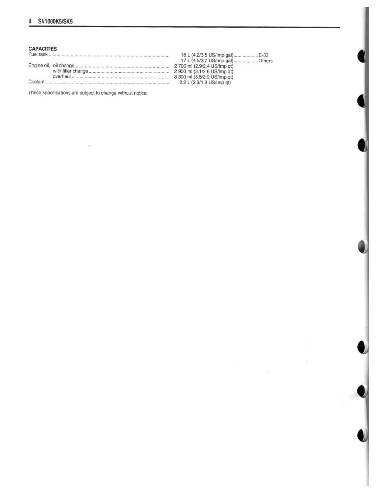
CAPAClTlES
Fuel
tank
.........................................................................................
Englne
oil,
nil
change
w~th
Cmlant
These
overhaul
........................................................................................
ylecjhcatims
....................................................
f~lter
change
.............................................................
......................
are
subject
......
to
change
...
....................................
without
notice.
......
2
2
3
16
17
700
900
300
2.2
L
(4.2B.5
L
(4.513.7
rnl
(2.912.4
ml
(3.112.6
ml
(3
L
(2.Y1.4
USllmp
'USlrnp
512.9
Uslmp
USlrnp
USllmp
USllmp
gal)
..................
...................
gal)
qt)
qt)
qt)
qt)
E-33
Others
Page 6
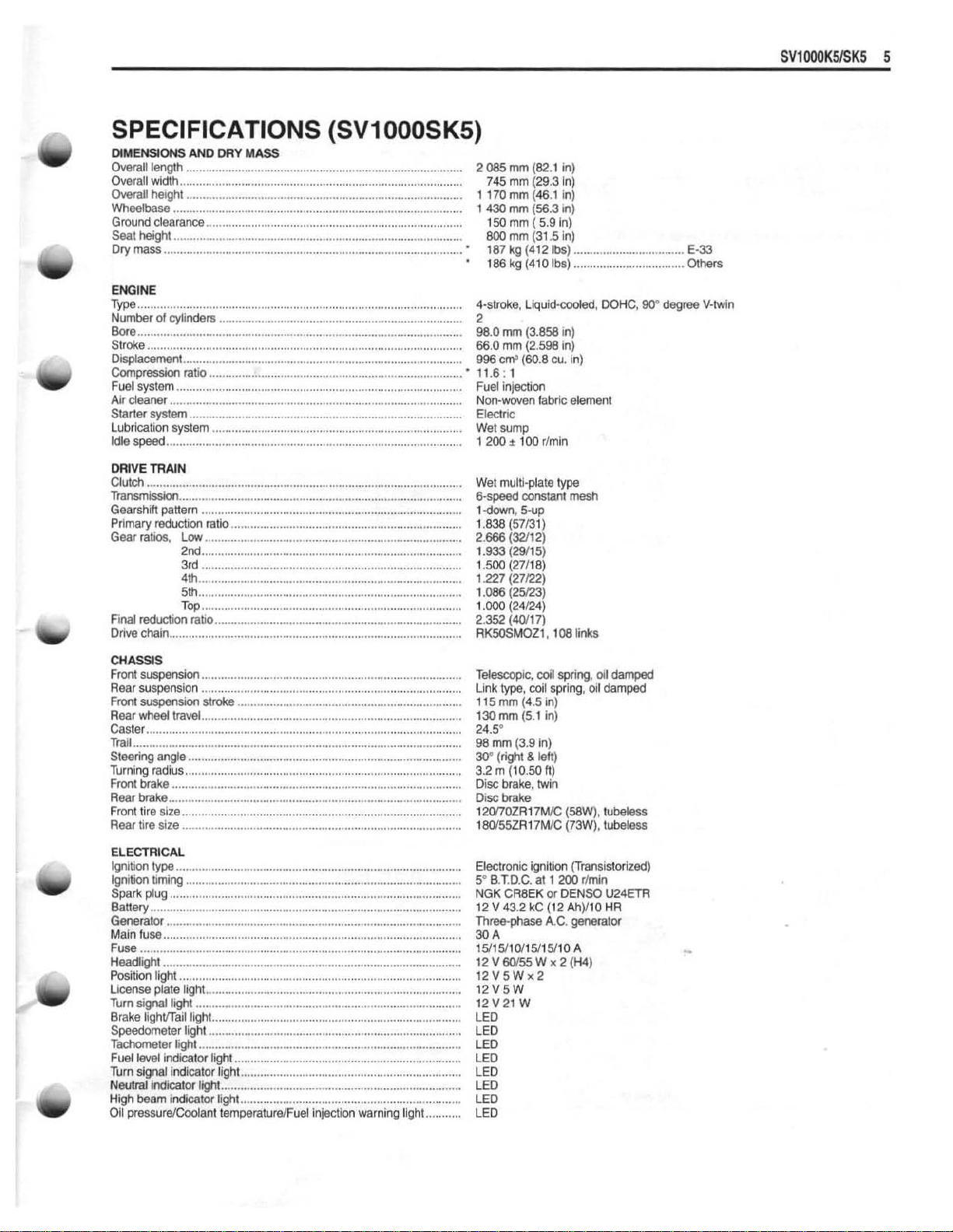
SPECIFICATIONS
DIME
NSlONS
Overalllength
Overall
Overall
Wheelbase
Ground
Seat
height
Dry
mass
ENGINE
Type
..................................................................................................
Number
Bore
..................................................................................................
Stroke
Dtsplacernent
Compression ratio
Fuel
system
Air cleaner
Starler
Lubrication system
Idle
sped
Clutch
Transmissian
Gearshift pattern
Primary
Gear
ratios.
Final
reduction
Drive
chain
AND
DRY
MASS
...................................................................................
widlh
....................................................................................
height
.....................................................................................
...................................................................................
clearance
............................................................................
.........................................................................................
............................................................................................
of
cylinders
.........................................................................
.................................................................................................
...................................................................................
..............................................................................
.....................................
........................
system
....................................................................................
..
...........................................................
..........................................................................
.....................
..
............................................................
................................................................................*............
.......................................................................................
...........................
reduction
ratio
Low
2nd
5th
Top.
....................
.......................................................................
...............................................................................
.......................
................................................................................
....................
ratio
............................................................................
..
..
..............................................................
(SVI
...
................................................
..
..............................................
......
..........................................
000SK5)
..................................................
2085rnm(82.1in)
745
mm
(293
1
170
mm
1
430
rnm
150
mm
800
tnm
'
187
kg
'
186
kg (410
Cstroke, Liquid-cooled,
2
W.Omm(3.858in)
660
mm
996
cm3
'
1
1.6
:
1
Fuel
Injection
Non-wwen fabric element
Electric
Wet
sump
I
200
+
Wet
multi-plate
6-sm
I
down,
1.838 (57131)
2.666
(3211
1.933
(29115)
1.500 (2711
1.227
(27122)
r
.oas
125123)
1.000
(24124)
2.352
(dOH
RKSOSMDZI
(46.1
(56.3
(
5.9
(31.5
(41
2
(2.598
(60.8
100
rSmln
constant
5-up
2)
8)
7)
,
In)
in)
in)
In)
in)
Ibs)
..................................
Ibs)
....................
In)
cu,
in)
type
rn~h
108
links
DOHC,
...
W
E-33
......
Others
degree
V-twin
CHASSIS
Front
suspensim
Rear
suspension
Frrm?
suspensim
Rear
wheel
Caster
.............
Trail
.....................................................................................................
Steering
Turning
radius
Front
brake
Rear
brake
Front tire
Rear
tlre
ELECTRICAL
Ignition
lyp
Ignition t~ming
Spark
plug
Battery
................................................................................................
Generalor
Main
fuse
Fuse
...................................................................................................
Headlight
Position light
License
Turn
signal
Brake I~ghbTail light
Speedometer llght
Tachometer
Fuel level indicator
Turn signal indicator light
Neutral
indicator
High
beam
Oil pressure1Coolant
................................................................................
................................................................................
stroke
travel
......
....................................................................................
angle
.....................................................................
................................................................................
.........................................................................
.....................................................................................
.........................................................................................
......................
size
..................................
......................................................................................
size
..
...............................................................
..,
.................................................
........................................................................................
...................................................................................
.........................................................................................
.........................................................................................
..........................................................................................
...........................................................................................
.......................................................................................
plate
ligM
...............................................................................
119111
..................................................................................
..........................................................................
..............................................................................
.................................................................................
light
light
......................................................................
....................................................................
light
ind~cator light
..........................................................................
....................................................................
temperaturelFuel
Inlection
warning
Ilght
...........
Telescopic,
Ltnk
1
15
130
24.5"
98
30"
3.2
Disc
DISC
120ffOZR171WC
180155ZR17MIC
Electronic
5"
NGK
12 V 43.2
Three-phase
30
15115HO/15/15/10
f2V60155Wx2(H4)
12Y5Wx2
12V5W
12Y21
LED
LED
LED
LED
LED
LED
LED
LED
cM1
type,
mm
mm
rnm
(righi
rn
(10.50
brake, twin
bake
B.T.D.C.
CR8EK
A
spring,
coil spring, or1
(4.5
In)
(5.1
in)
(3.9
in)
&
left)
ft)
(58W),
(73W),
ignition (Trans~storizad)
at
1
200
or
DENSO
kc
(1
2
Ah)/lO
A.C.
generam
A
W
rlrnin
01
damped
damped
tubel~ss
tubeless
U24ETR
HR
Page 7
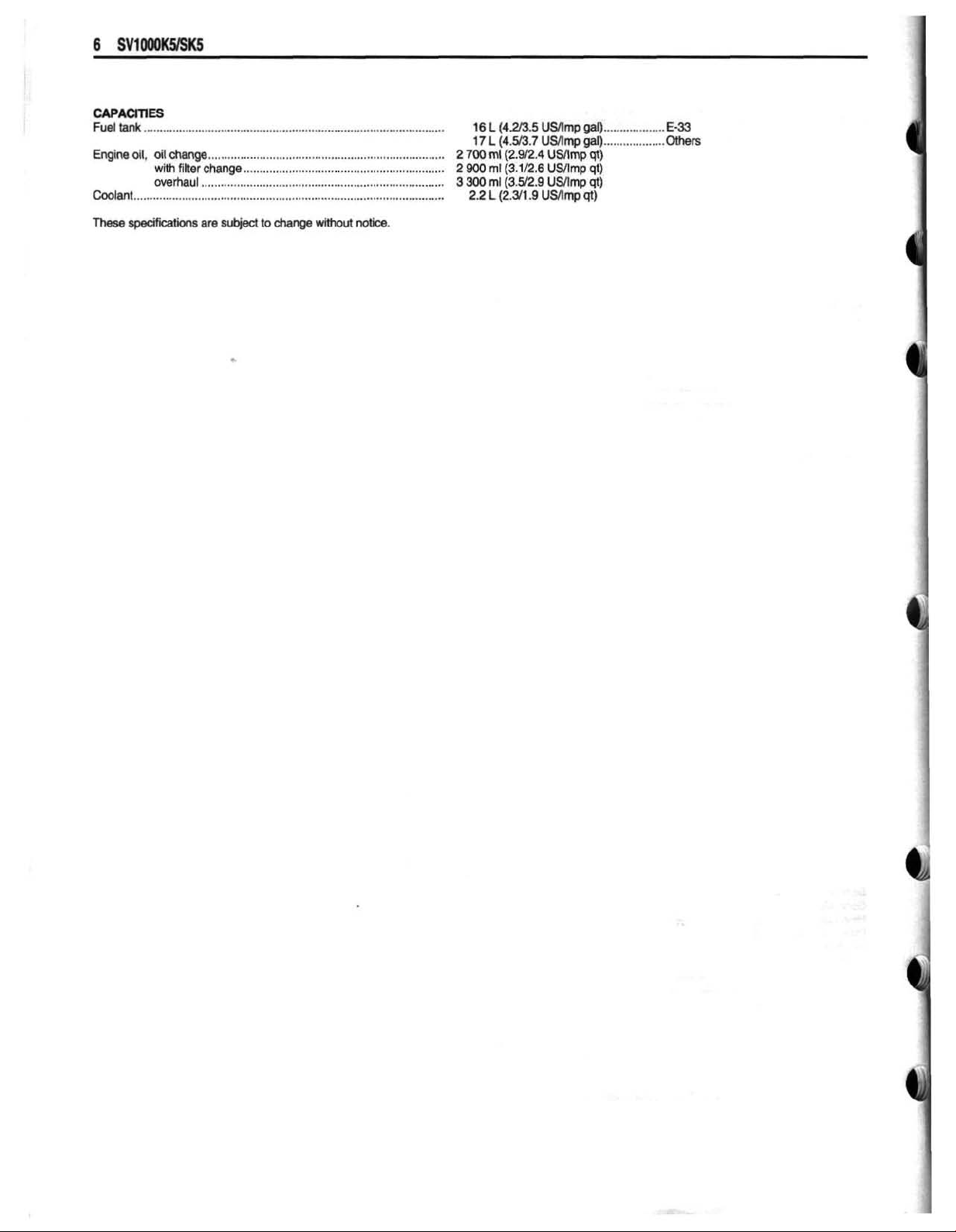
CAPmES
Fueltank
Eqine
Coolant
Them
............................................................................................
d,
al!
change
wrth
overhaul
.........................................................................
filter
change
..............................................................
.........................
..
................................................
..........................................................................................
sp&kths
am
srlbiect
to
change wilhout
natlce.
16L(4.2/3.5USnmpgal)
17
L
(4.93.7
2
2
3
300
900
300
2.2
rnl
rnl
rnt
L
(2.912.4
(3.1/2.6
(3.5/2.9
(2.3
1.9
USnrnpgal)
USllrnp
USllmp
INtmp
US/lmp
...................
..................
qt)
qt)
qt)
qt)
E-33
Oltiers
Page 8

SERVICE
DATA
(SVI
000K5)
Ic,
VALVE
Valve
stem
Valve
stem
Valve
stem
+
GUIDE
0.0.
deflection
runout
IN.
EX,
IN.
8
EX.
IN. & EX.
5.475 - 5.490
(0.21
56
-
0.21
5.455
-
48
5.470
-
0.21
(0.21
-
61)
54)
Unit:
-
-
0.35
(0.01
mm
4)
(in)
b
Valve
head
thickness
Valve
head
radial
Valve
Valve
spring
spring
free
tension
CAMSHAFT
ITEM
Camshaft
Camshaft
Camshaft
journal
journal
journal
runout
length
+
CYLINDER
oil
clearance
holder
O.D.
I.D.
IN.
& EX.
IN. & EX.
IN.
&
EX.
IN.&EX.
HEAD
--
EX.
IN. & EX.
---
IN. & EX.
IN. 8 EX.
-
(0,035
(20.1-23.1kgf,44.3-51.0lbs)
at
length
STANDARD
*37.18-37.22
(0.0007
22.012
(0.8666 - 0.8671
21.972 - 21.993
(0.8650
-
0.043)
-
-
197-227
35.6
{I
.464
0.01 9 - 0.053
rnm
-
1
"465)
-
0.002 1 )
-
22.025
-
0.8659)
N
(1
-40
in)
-
0.5
(0.02)
0.03
(0.001)
41.2
(1
32)
-
Unit:
mm
LIMIT
36.88
(1.452)
0.1
50
(0.0059)
-
-
(in)
Page 9
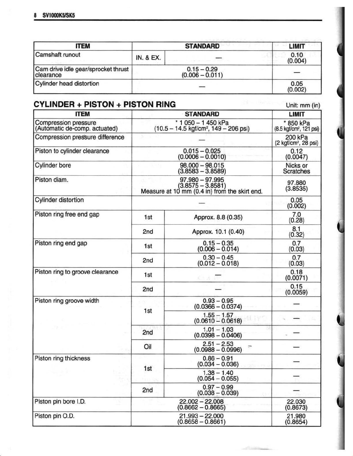
Camshaft
Cam
drive
clearance
Cylinder
head
ITEM
runowt
idle
gear/sprocket
distortion
thrust
IN.
&
EX.
STANDARD
-
0.1
5
-
0.29
-
1
LIMIT
0.10
(0.004)
0.05
(0.002)
CYLINDER
Compression
(Automatic
Compression
I
Piston
Piston
(Cylinder
Piston
Piston
Piston
de-comp.
to
cylinder
diarn.
distortion
ring
free
ring
end
ring
to
+
PISTON
lTEM
pressure
actuated)
pressure
end
gap
gm
difference
clearance
gap
clearance
+
PISTON
RING
(1
0.5
Measure
-
at
STANDARD
*
1
050
14.5
kgf/crn2,
97.980
(3.8575
10
rnm
Approx.
-
1
450
149
-
-
97.995
-
3.8581)
(0.4
in)
from
Approx.
kPa
8.8
1
0.1
-
206
the
(0.35)
(0.40)
psi)
skirt
end.
(8.5
(2
1
1
--
I
Unit:
mrn
LIMIT
'
850
kPa
kgf/cm2,
kgf/crn2,
Scratches
121
200
kPa
28 psi)
Nicks
or
97.880
(33535)
(in)
psi)
I
Piston
Piston
Piston pin
Piston
ring
ring
pin
grow
thickness
bare
O.D.
width
1.0.
Oil
2.51
10,0988
-2.53
-
0.09961
-
Page 10
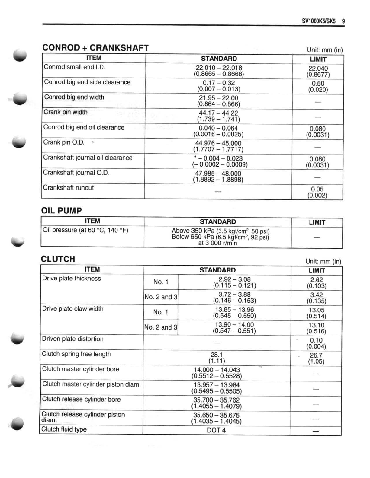
CONROD
Conrod
Conrod
Can
Crank
Conrod
Crank
Crankshaft
Crankshaft
Crankshaft
OIL
Oil
small
big
rod
big
pin
width
bis
end
-
pin
O.D.
journal
journal
runout
PUMP
pressure
+
CRANKSHAFT
end
I.D.
end side clearance
end
width
oil
clearance
oil
clearance
O.D.
ITEM
(at
60
"C,
140
OF)
Above
Below
22.01
0
-
22.018
(0.8665
(0.007
(0.864
(1.739
(0.001
44.976 - 45.000
11.771)7
\
*
-
(-
47.985
(1.8892
-
0.17-
-
21.95
-
-
44.1
7
-
-
6.040
-
6
-
-
"
-
0.004
0.0002
-
-
-
0.8668) (0.8677)
0.32
0.01
22.OQ
0.866)
44.22
1.741)
0.064
0:0625)
1
77171
...
-
0.023
0,0009)
48.000
1.8898)
-
STANDARD
350
kPa
(3.5
650
at
kPa
3
(6.5
000
kgflcm2,
kgf/cm2,
rlrnun
3)
.
-
"I
50
92
psi)
psi)
Unit:
mm
LIMIT
22.040
0.50
(0.020)
-
-
0.080
(0.0031
)
-
0.080
(0.0031)
-
0.05
(0.002)
LIMIT
-
Fin)
-
1
CLUTCH
Unit:
mm
tin)
Page 11
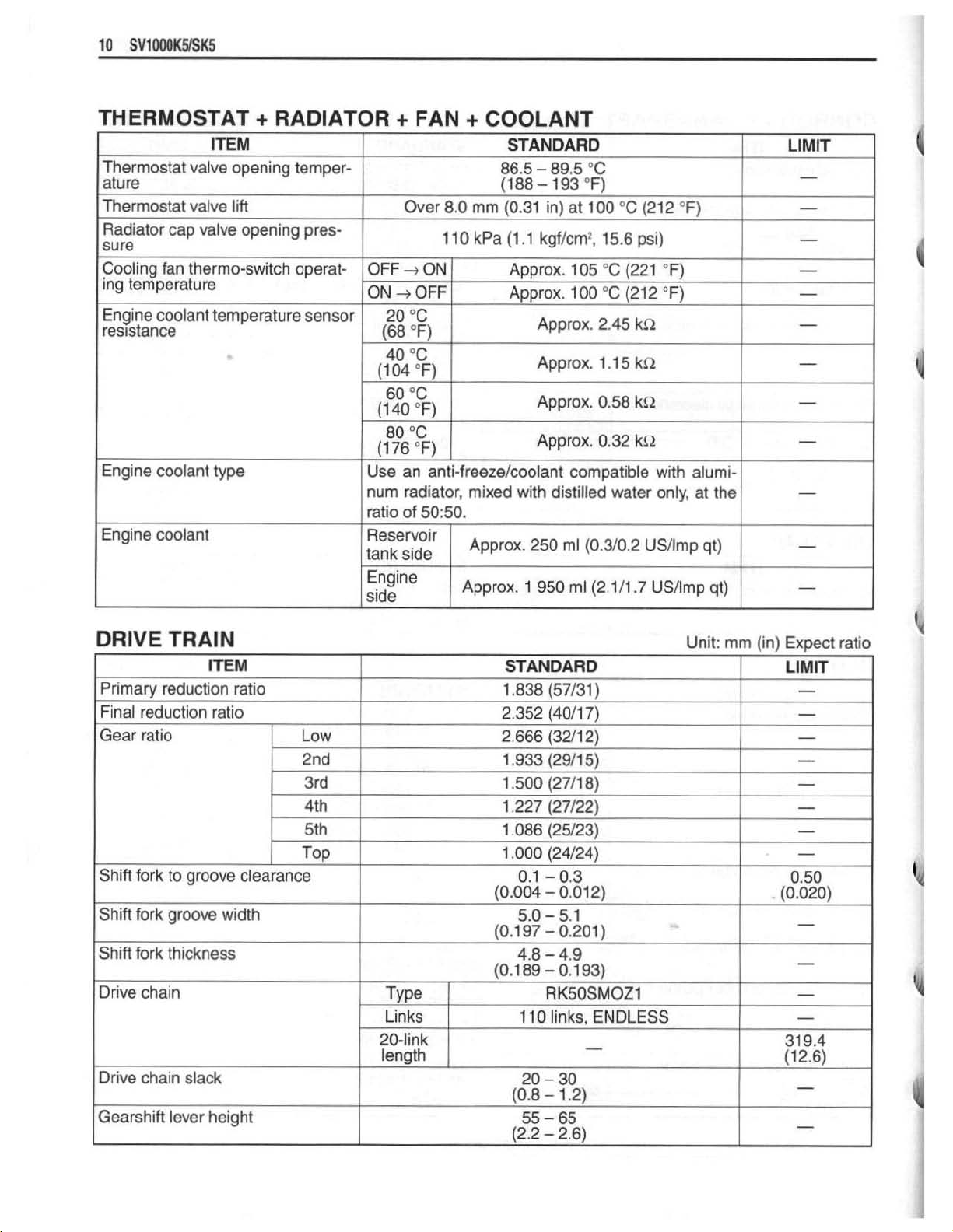
THERMOSTAT
+
RADIATOR
+
FAN
+
COOLANT
r,
a
11
DalvE
Shift
fork
Drive
chain
Drive
chain
Gearshift
TRAIN
thickness
slack
lever
height
Type
Links
20-link
length
4.8 - 4.9
(0.1
89
1
20
(0.8
55
(2.2
-
0.193)
RKSOSMOZ1
10 links,
ENDLESS
-
-
30
-
1.2)
-
65
-
2.6)
-
-
-
31
9.4
(12.6)
-
-
'4
'A
I
.i
Page 12
'u
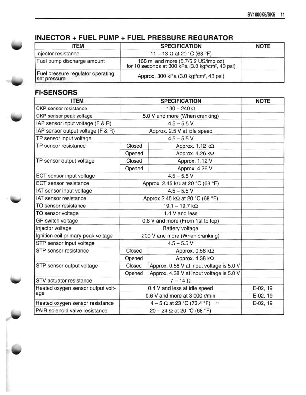
INJECTOR
Injector
Fuel
Fuel
set
resistance
pump
pressure
pressure
discharge
+
FUEL
ITEM
amount
regulator
PUMP
-
operating
+
FUEL
I
for
PRESSURE
11
168
ml
70
Approx.
and
seconds
REGURATOR
SPECIFICATION
-13I1at20
more
at
300
300
kPa
"C
(5715.9
kPa
(3.0
(3.0
kgf/cm2,
(68OF)
USArnp
kgf/cm2,
43
oz)
43
psi)
psi)
Page 13
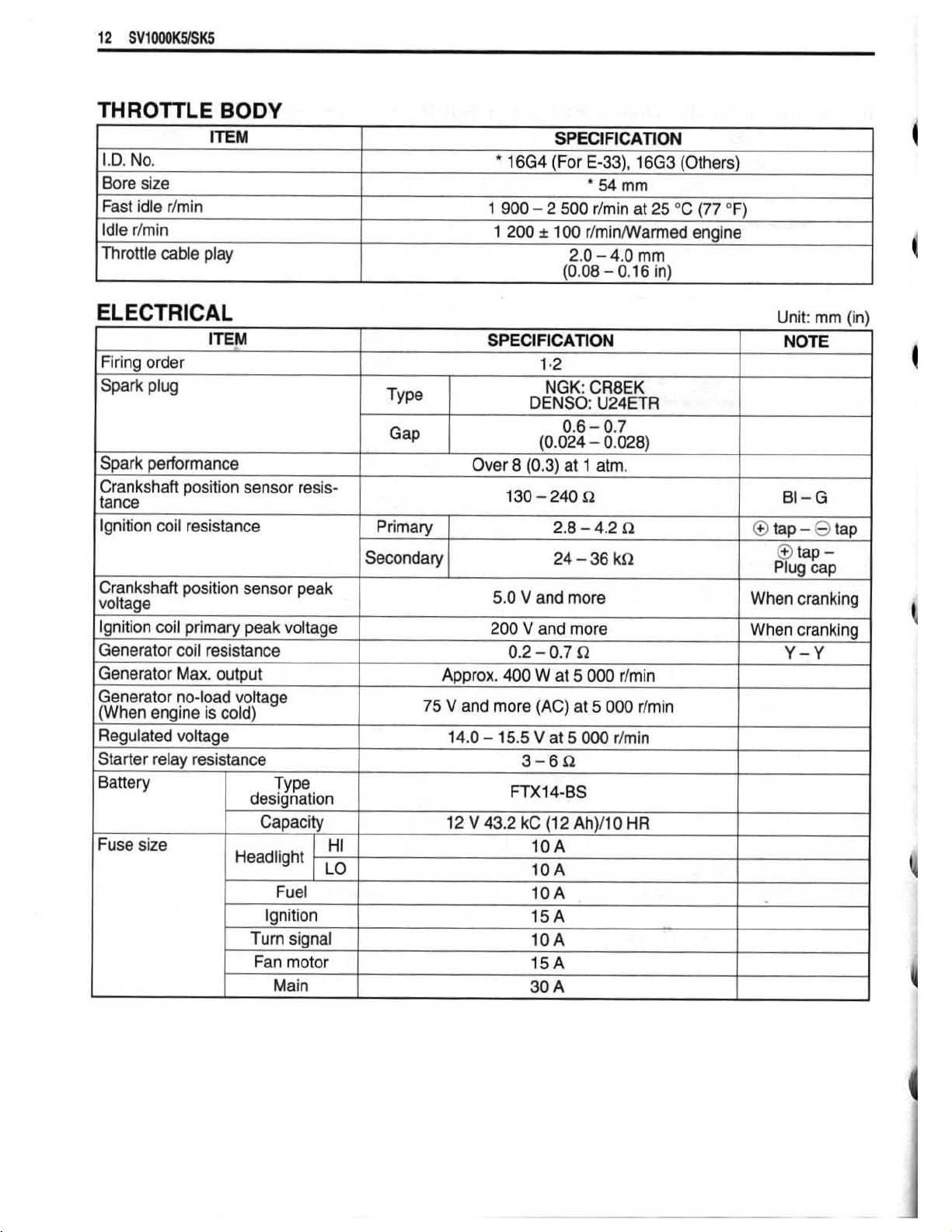
THR0fT"LE
If
I.D.
No.
Bore
size
Fast idle rim
Idle
r/min
Throttle
in
cable
play
BODY
EM
*
16G4
1
900
1
200
SPECIFICATION
(For
E-33),
54
mrn
-
2
500
rlmin
A
10Q
r/rnin#armed
2.0
-
4.0
(0.08
-
0.1
16G3
at
25
mrn
6
in)
(Others)
"C
(77
T)
engine
ELECTRICAL
ITEM
Firing order
Spark
Spark performance
Crankshaft
tance
Ignition
Crankshaft
voltage
Ignition
Generator
Generator
Generator
(When
Regulated
Starter
1
plug
position
coil
resistance
position
coil
primary
coil
resistance
Max.
output
no-load
engine
relay resistance
is
cold)
voltage
sensor
sensor
peak
voltage
resis-
peak
voltage
TY
pe
Gap
I
prnary
1
Secondary
Approx.
45 V
Over
and
14.0
SPEC!
8
130
5.0
V
200
0.2
400
more
-
15.5
FlCATlON
1.2
NGK:
DENSO:
0.6
(0.024
(0.3)
at
-
240
2.8
-
24
-
and
more
V
and
more
-
0.7
S2
W
at
5
(AC)
at
V
at
5
3-6rR
CR8EK
V24ETR
-
0.7
-
0.028)
1
atm.
f2
4.2
il
36
kR
000
rlrnin
5
000
000
rlrnin
rlmin
Unit:
rnm
NOTE
BI-G
4
]
@tap-@tap
I+>
tap
Plug
cap
When
When
cranking
cranking
Y-Y
-
linl
,
I
I
Fuse
size
U
Capacity
/
Headlight
Fuel
Ignition
Turn
Fan
signal
motor
HI
LO
I
12
V
43.2
kC
(12
10
A
10
A
IOA
f
5
A
10
A
15
A
Ah)/lO
HR
I
I
I
II
Page 14
b
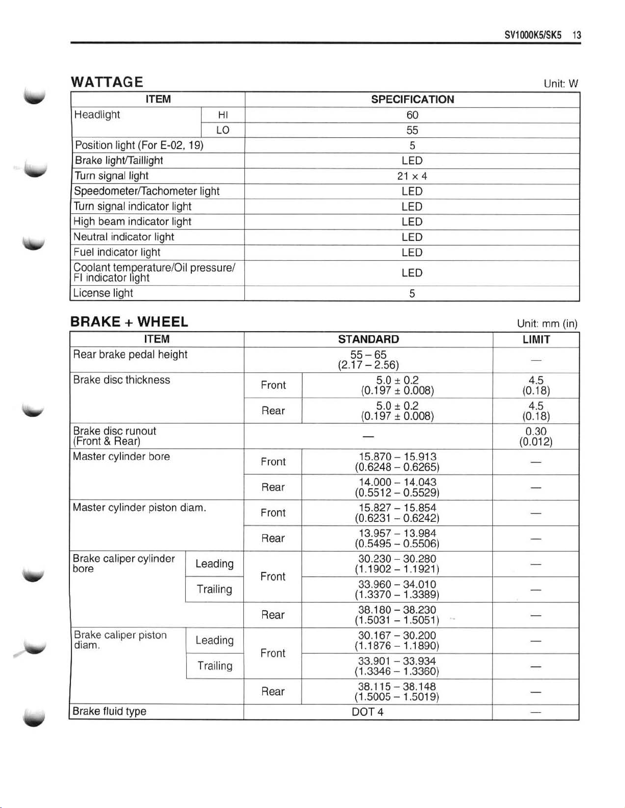
WATTAGE
ITEM
Headlight
Position light (For
Brake
Turn signal light
Speedometerfrachometer light
Turn
High
Neutral indicator light
Fuel indicator light
Coolant
FI indicator l~ght
License
IightlTaillight
signal indicator light
beam
indicator light
temperaturelOil pressure/
light
E-02,
19)
HI
LO
SPECIFICAIION
60
55
5
LED
21
x4
LED
LED
LED
LED
LED
LED
5
Unit:
W
b
w
w
BRAKE
I
Rear
Brake
Brake
(Front & Rear)
Master cylinder bore
Master
Brake caliper cylinder
bore
Brake
diam.
Brake fluid
+
WHEEL
ITEM
brake
pedal height
disc
thickness
disc runout
cylinder piston
caliper
piston
type
diarn.
Leading
Trailing
Leading
Trailing
1
1
Front
Rear
Front
Rear
Front
Rear
Front
Rear
Front
Rear
I
1
STANDARD
5.0
rt:
0.2
(0.1
97
0.008)
-
15.870
(0.6248
15.827
10.6231
13.957
10.5495 - 0.55061
30.230
(1.1902
33.960
(1.3370
38.1 80
(1
30.1 67 - 30.200
(1.1876- 1.1890)
33.901 - 33.934
(1.3346
38.1
(1.5005
DOT
-
15.91
-
0.6265)
-
15.854
-
0.6242)
-
13.984
-
30.280
-
1.1921)
-
34.01
-
1.3389)
-
38.230
-5031 - 1.5051)
-
1.3360)
15
-38.148
-
1.501
4
3
0
9)
Unit:
LIMIT
-
4.5
(0.1 8)
0.30
(0.01
-
-
-
-
-
-
-
-
-
-
mrn
--
2)
(in)
Page 15
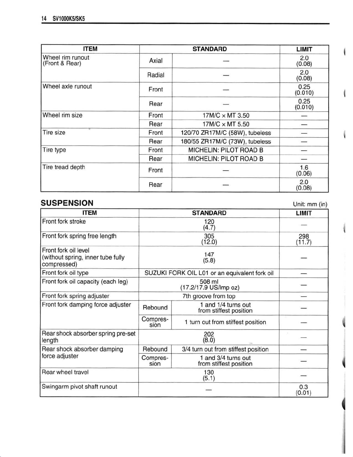
SUSPENSION
m
Front
fork
stroke
Front
fork
Front
fork
(without
corn
Front
Front
Front fork
Front
Rear
length
Rear
force
Rear
Swingarm
spring,
p
ressed)
fork
fork
fork
shock
shock
adjuster
wheel
spring
oil
oil
oil
spring
damping
free
level
inner
type
capacity
adjuster
absorber
absorber
travel
pivot
shaft
length
tube
(each
force
adjuster
spring
damping
runout
fully
leg)
pre-set
SUZUKl
Rebound
FORK
COmPres-
sion
Rebound
Cornpres-
sion
I
STANDARD
(1
OIL
LO1
7.211
7th
1
508
7.9
groove
1
from
turn
turn
1
(1
314
from
120
(4.7)
305
2.0)
1
49
15-81
or
rnl
USllmp
from
and
stiffest
out
from
202
(8.0)
out
from
and
314
stiffest
1
30
(5.11
.I
-
an
equivalent
oz)
top
114
turns
position
stiffest
stiffest
turns
~osition
fork
out
position
position
out
oil
Unit:
LIMIT
-
298
(1
1.7)
-
-
-
-
-
-
-
-
-
-
0.3
10.01
mrn
1
(in)
I
Page 16

TlRE
PRESSURE
COLD
TIRE
FRONT
I
FUEL + OIL
Fuel
type
Fuel tank
Enaine
--
Engine
oil
me
oikapacity
INFLATION
PRESSURE
REAR
ITEM
SOLO
kPa
250
I I I
RIDING
kgflcm2
2.50
250
SPECIFICA~ON
Use
only
octane
the
(Methyl
nol,
cosolvents
Gasoline
I
higher.
1
(R/2 + M12)
research
or
An
SAE
10W-40.
Change
Tertiary
less
unleaded
than
and
used should
unleaded
1
17
gasoline
or
method.
Butyl
5%
corrosion
qasoline
6
L
(4.213.5
L
(4.513.7
API
SFlSG
I
psi
36
36
of
91
octane
Gasoline containing
Ether),
methanol
less
inhibitor
be
graded
is
'USllrnp gal)
USArnp
or
SHJSJ
kPa
--
250
I
290
at
least
87
or
higher
than
10%
with
appropriate
is
wrmissi
91
octane
recommended.
gal)
with
JASO
DUAL
kgf/cm2
I I
e
pump
rated
by
MTBE
elha-
ble.
or
MA
RIDING
2.50
2-90
/
The
The
e
.-
NOTE
E-33
others
E-33
-
others
psi
36
42
-
I
I
I
filter
change
Overhaul
2
(3.112.6
3
E3.512.9
900
ml
USHmp
300
rnl
US/lmp
qt)
qt)
-
Page 17

SERVICE
VALVE
+
GUIDE
DATA
(SVI
000SK5)
Unit:
mm
(in)
@
Valve
Valve
spring
spring
free
length
tension
CAMSHAFT + CYLINDER
ITEM
Cam
height
~
Camshaft
I
Camshaft
Camshaft
journal
journal
journal
oil
clearance
holder
O.D.
I.D.
IN.
&
EX.
IN.&EX.
HEAD
IN.
UC.
IN. & EX.
IN.
&
EX.
IN. & EX.
-
197
-
227
(20.1-23.1kgf,44.3-51.0Ib~)
at
length
STANDARD
35.6
37.78
(1
-487
*
37.18
(1.464
0.01
9
(0.0007
22.012
(0.8666
21,972
(0,8650
N
mm
-
37.82
-
1.489)
-
37.22
-
1.465)
-
0.053
-
0.0021)
-
22.025
-
0.8671)
-
21.993
-
0.8659)
(1.40
in)
I
41.2
(1.62)
-
Unit:
mrn
LIMIT
37.48
(1.476)
'
36.88
(1.452)
0.150
(0.0059)
-
-
(in)
14
1
Page 18

Camshaft
Cam
drive
clearance
Cylinder
head
ITEM
runout
idle
gearlsprodcet
distortion
thrust
IN.
&
EX.
STANDARD
0.1
5
-
0.29
(0.006
-
0.01
-
-
I)
LIMIT
0.10
(0.004)
-
0.05
(0.002)
Piston
Piston
Piston
Piston
Piston
ring
ring
ring
pin
pin
bore
O.D.
to
groove
groove
thickness
width
I.D.
clearance
2nd
I
st
2nd
1
st
Oil
I
st
2nd
Approx,
(0,012
0.30
1
-
-
0.1
-
-
0.93
1.55
0
1.01
2.51
0.86
1.38-
0.97
-
22.008
-
0.8665)
-
0.8661)
-
-
-
-
-
-
-2.53
-
-
-
-
-
-
(0.0366
(0.061
(0.0398
(0.0988
(0.034
(0.054
(0.038
22.002
(0.8662
21.993 - 22.000
(0.8658
(0.40)
0.45
0.01
8)
0.95
0.0374)
1.57
0.061
8)
1.03
0.0406)
--
0.0996)
0.91
0.036)
1.40
0.055)
0.99
0.039)
0.7
(0.03)
0.18
(0.0071)
0.3
5
(0.0059)
-
-
I
-
-
-
-
22.030
(0.8673)
-
21.980
(0.8654)
Page 19

COMROD
+
CRANKSHAFT
Unit:
mrn
(in)
Crankshaft
OIL
PUMP
Oil
pressure
CLUTCH
rive
plate
runout
EM
(at
60
thickness
"C,
140
OF)
Above
Below
STANDARD
350
kPa
650
kPa
at
3
000
(3.5
kgflcm2,
(6.5
kgflcm2,
rlrn~n
50
92
psi)
psi)
0.05
(0.002)
LIMIT
-
Unit:
mm
(in)
Page 20

SVf000MK5
19
THERMOSTAT
+
RADIATOR
+
FAN
+
COOLANT
DRIVE
Primary
Final
reduction
ratio
Gear
Shift
fork
Shift
fork
Shift
fork
Drive
chain
Drive
chain
Gearshift
TRAIN
ITEM
reduction
ratio
to
groove
groove
thickness
lever
width
slack
height
ratio
clearance
Low
4th
5th
TOP
TYPE
Links
20-link
length
STANDARD
1
-838
(57131
2.352
(4011
2.666
13211
1
-227
(27122)
1.086
(25123)
1
.OOO
(24124)
0.1
-
(0.004
(0.1
(0.1
(0.8
(2.2
0.3
-
0.01
5.0
-
5.1
97
-
0,201)
4.8
-
4.9
89
-
0.1
RK50SMOZ1
108
links,
20
-
30
-
1.2)
55
-
65
-
2.6)
)
7)
2)
2)
93)
ENDLESS
-
Unit:
mm
(in)
Expect
..
LIMIT
-
-
ratio
.
1
-
-
-
-
0.50
(0.020)
-
L.
-
-
-
31
9.4
(12,6)
-
-
Page 21

INJECTOR
+
FUEL
PUMP
+
FUEL
PRESSURE REGURATOR
ITEM
Injector
Fuel
Fuel
set
resistance
pump
discharge
pressure
pressure
regulator operating
FI-SENSORS
amount
SPEClflCATlON
11
-1312at20nC(68"F)
168
rnl
and
more
(5.715.9
for
10
seconds
,
Approx.
at
300
300
kPa
kPa
(3.0
USAmp
(3.0
kgf/cmz,
kgflcm2,
43
oz)
43
psi)
psi)
NOTE
Page 22

SV1000K51SK5
21
THROITLE
I.D.
No.
Bore
size
Fast
idle
,
Idle
Throttle cable play
rlmin
rlmin
BODY
ITEM
ELECTRICAL
I
I
Crankshaft
tance
Ignition
Crankshaft
volta~e
Ignition
1
Generator coil resistance
I
Generator
Generator no-load
(When
I
Regulated
Starter
Battery
Fuse
coil
-
coil primary
enaine
relay
sire
ITEM
position
resistance
position
Max. output
"
voltage
resistance
sensor
sensor
voltage
is
cold)
Headlight
1
peak
designation
Capacity
Ignition
Turn
Fan
--
resis-
-
-
-.
peak
voltage
?YP~
HI
LO
Fuel
signal
motor
Main
TYPE
Primary
Secondary
1
1
75
I
1664
1
900
3
200
SPECIFICATION
Over
8
5.0 V and
200
0.2
Approx.
V
14.0
12 V 43.2
and
-
400
more
15.5 V at
FIX1
SPEClFlCAllON
(For
E-33),
*
54
-
2
500
rlmjn
I00
rJminMJarmed
2.0
-
(0.08
-
1.2
NGK:
DENSO:
(0.3)
V
and
-
W
(AC)
CR8EK
U24ETR
at
1
atm,
2.8-4.2
24
-
36
more
more
0.7
0
at
5
000
at
5
5
000
000
3-6R
4-BS
kc
(I2
Ah)/lO
15
A
15
A
10
A
15
A
70
A
15
A
30
A
16G3
mrn
at
4.0
0,16
IR
kXl
r/min
rfmin
HR
(For
25
mm
in)
rimin
.+
others)
"C
(77
engine
OF)
Unit:
NOTE
I
@
tap
-
@
tap
-
/
When
I
I
1
cranking
When crankina
Y-Y
I
mm
--
@
tap
Plug
(in)
,
cap
.
I
I
1
Page 23

Unit:
W
BRAKE
Rear brake
Brake
disc
Brake
disc
{Front
&
Rear)
Master
Master
Brake
bore
Brake
diam.
Brake
cylinder
cylinder
caliper
caliper
-
fluid
+WHEEL
pedal
he~ght
thickness
runout
bore
piston
cylinder
piston
type
diam.
Leading
Trailing
Leading
Trailing
---
Front
Rear
Front
Rear
Front
Rear
Front
Rear
Front
Rear
STANDARD
55
-
65
(2.17
-2.56)
5.0
(0.197
k
A
5.0 2 0.2
(0.1
97
it
-
15.870
(0.6248
14.000
(0.551
15.827
(0.6231
13.957
(0.5495
30.230
(1.1902 - 1.1921)
33.960
(1.3370
38.1
(1 5031
30.167
(1.1876-
33.901 - 33.934
(1
38.1
(1.5005 - 1.501
DOT
-
-
-
2
-
-
-
-
-
-
-
-
80
-
-
-
-3346
-
15-38.148
4
0.2
0,008)
0.008)
15.91
3
0.6265)
14.043
0,5529)
15.854
0.6242)
13.984
0.5506)
30.280
34.01
0
1.3389)
38.230
1.5051
30.200
1.1890)
1.3360)
1
pp
9)
Unit:
mm
(in)
LIMIT
-
4.5
(0.1
4.5
(0.18)
0.30
(0.01
8)
2)
I
-
-
-
-
-
I
-
-
-
-
-
-
Page 24

w
SUSPENSION
Unit:
mm
(in)
Page 25

TIRE
PRESSURE
COLD
TIRE
INFLATION
PRESSURE
FRONT
REAR
kPa
250
250
SOLO
kgf/cm2
2.50
2.50
RIDING
psi
36
36
kPa
250
290
DUAL
kgflcrn2
2.50
2.90
RIDING
psi
36
42
FUEL
Fuel
type
Fuel
tank
I
Engine oil
Engine
+
OIL
type
oil
capacity
ITEM
Use
only
unleaded
octane
the
(Methyl
nol,
cosolvents
Gasoline
higher.
*
Filter
(R12 + M12)
research
Tertiary
or
less
An
SAE
10W-40,
Change
change
Overhaul
used
SPECIFICATfON
gasoline
or
91
octane
method.
Butyl
than
and
corrosion inhibitor
should
unleaded gasoline
16
L
17
L
API SFlSG
Gasoline
Ether),
5%
methanol
be
(4.2/3.5
(4.513.7
graded
USnrnp
USIlmp
or
(2.912.4
(3.112-6
(3.U2.9
of
at
least
or
higher
containing
less
than
10%
with
appropriate
is
permissible.
91
is
recommended.
gal)
gal)
SHISJ
2
2
3
700
rnl
USllmp
900
ml
US/lmp
300
ml
USllrnp
with
qi)
qt)
qt)
87
pump
rated
MTBE
etha-
octane
JASO
by
or
MA
NOTE
E-03,
The
E-33
The
28,
33
others
others
Page 26

CRANKCASE-CRANKSHAFT
Select
The
the
the
specrffed
crankcase
inside
of
bore
each
bearings
I.D.
code
crankcase
from
(A)
half.
the
crankcase
"A,
"6"
or
"C",
BEARING
bore
I.
D.
code.
is
stamped
on
SELECTION
Bearing
I.D.
Bearing
(1
(1
(I
-1
Bearing
selection
code
@9
A
B
C
thickness
Color
(Part
Green
2229-1
Black
2229-
tGG00-OBO)
Brown
2229-
16GOO-OCO)
must
6GOO-OAO)
table
I.P.
specification
52.000
(2.0472
52.006
(2.0475
52.01
(2.0477 - 2.0479
No.)
be
replaced
2
-
-
-
52.006
-
2.0475
52.01
2
-
2.0477
52,018
as
a
set.
mrn
in)
mm
in)
mm
in)
Thickness
1.999
-
2.002
(0.0787
2.002
(0.6788
2.005 - 2.008
(0.0789
-
0.0788
-
2.005
-
0.0789
-
0.0791
Bearing
Green
Black
Brown
mrn
in)
mm
in)
rnm
in)
Color code
9
Page 27

FI
SYSTEM
WIRING DIAGRAM
Page 28

I
'&
ECM
TERMINAL
(For
KCModel)
Page 29

ECM
TERMINAL
(For
K5-Model)
Page 30

&
FAIL-SAFE
FI
system
mum
is
provided
performance
FUNCTION
with
fail-safe
necessary
even
function
under
ta
allow
the
malfunction
engine
condition.
to
start
and
the
motorcycle
to
run
in
a
mini-
'hb
PAIR
control
The
engine
running
essary
to
solenoid
can
start
condition
bring
the
valve
and
can
is
not
complete,
motorcycle
gear.
02
PAIR
run
even
providing
to
the
feedback
valve
is
if
the
workshop
control
fixed
above
only
emergency
for
is
stopped
to
open
signal
complete
is
and
position.
not
received
help
(by
repair.
"YES"
from
fail-safe
each
sensor.
circuit).
In
this
"YES"
But,
the
case,
engine
it
is
nec-
Page 31

MALFUNCTION
CODE
AND
DEFECTIVE
CONDITION
MALFUNCT'ON
CODE
COO
C12
C14
C15
C17
C2
I
C23
--
C24
or
C25
1
DETECTED
1
NO
FAULT
Crankshaft position
sensor
lntake air
sensor (Front)
Throttle position
sor
Engine coolant ternperature sensor
lntake air pressure
sensor
lntake
sensor
I
Tip over sensor
Ignition signal
(Rear)
air
ITEM
pressure
sen-
temperature
DETECTED
The
signal
does
not reach
receiving the starter signal.
The crankshaft position sensor wiring and mechanical parts
(Crankshaft position sensor, wiringlcoupler connection)
When incorrect
tion, C13 is indicated.
The sensor should produce following voltage.
(0.50
V
5
Without the
lntake air
The sensor should produce following voltage.
(0.20
V
2
Without the above range,
Throttle position sensor, wiringlcoupler
The
sensor voltage should
(0.15
V
5
Without the
Engine coolant temperature sensor,
When incorrect vacuum hose
tion,
C17
The sensor should
(0.50
V
5
Without
l ntake
The sensor
(0.15
Without the above range,
Intake air temperature sensor, wiringlcouplex connection
The
after
(0.20
Without the above
Tip over sensor, wiringlcoupler connection
the
air
V
2
sensor voltage
ignition switch turns
V
5
vacuum
sensor voltage
above
pressure
sensor voltage
sensor voltage
above
is indicated.
sensor voltage
above range,
pressure sensor, wiringlcoupler connection
voltage
sensor voltage
sensor
range,
sensor, wiring/coupler connection
range, C15 is indicated.
produce
should
should
voltage
value,
FAILURE CONDlTlON
CHECK
ECM
hose
C13
C14
C17
C21
ON.
C23
FOR
for
more
than
2
sec,
andlor lead wire coupler connec-
4.85
V)
is
indicated.
4.80
V)
is indicated.
connection
be
the
following.
4.85
V)
wiringlcoupler connection
andlor lead wire coupler connec-
following voltage.
4.85
V)
is
indicated.
be
the following.
4.85
V)
is
indicated.
be
the following
4.80
V)
is
indicated.
for
more than
after
2
sec.
~
mines the ignition signal but signal from ignition coil
rupted continuous
C24
or
C25
Ignition coil, wiringlcoupler connection, power supply from the
battery
by
4
times or more. In this
is indicated.
case,
is
inter-
the code
-
Page 32

C32
C49
C28
C29
C31
or
C33
C4
1
C42
c44
Secondary
valve
actuator
Secondary
valve
position
Gear
position signal
Fuel
injector
Fuel
pump
Ignition
Heated
(H02S)
PAlR
valve
switch
oxygen sensor
ForE-02,19
control
(PAIR
throttle
throttle
sensor
relay
solenoid
valve)
When
communication
age
not
STVA
The
(0.1
Without
Secondary
Gear
for
(Gear
Without
Gear position
no actuator
does
not
operate.
lead
wire/coupler,
sensor
0
more
should
V
5
sensor
the
above
throttle position
position signal
than 2 seconds.
position
the
above
control
signal
reach
produce
voltage
range,
switch
value,
sensor,
signal
does
STVA
motor,
STVA
C29 is indicated.
voltage
voltaga
C31
wiringlmupler connection,
etc.
Crankshaft
mines
continuous
C33
is
Injector,
No
voltage
turned
pump
Fuel
pump
position
the injection
by
4
times
indicated.
wiringlcoupler
is applied
ON,
or
voltage
relay
is
turned
relay,
connecting lead,
sensor
signal
or
but
more.
connection,
to
fuel
is
applied
OFE
relay
Ignition
Ignition switch,
During
lowerthanthespecification.
No
power
H02S
Battery
When
indicated.
PA1 R valve lead wirelcoupler
switch
02
signal
is
lead
voltage
no
signal
lead
feedback
is
detected
supplied
wirelcoupler
supply
operating
PAIR
valve
b
not
wirelcoupler
control,
during
from
the
battery.
connection
to the
voltage
can
not
is
supplied
not
reatch
followjng
4.90
sensor,
should
s
is
signal
fuel
In
ECM
C28
is
indicated.
voltage.
V)
wiringlcoupler
be
higher
0.6
V)
indicated.
is
produced
injection
this
case,
power
pump although
to
fuel
pump although fuel
power
input
in
02
sensor
engine
H02S
is supplied from
operate.
source
the
ECM.
voltage
operation
from
the
or
operation volt-
connection
than
geatshi
and
signal
is
the
code
supply
fuel
or
the
to
pump
to
is
higher
no
ECM,
ECM,
S'PJA
can
the
following
cam,
ECM
deter-
intempted
C32
or
the
injector
relay
fuel pump
or
electrical
C49
is
is
Page 33

FI
SYSTEM
Due
to
shown
On
model
ily
at
the
NOTE:
To
measure
used
with
change
in
page
K5,
ECM
vmge,
the
wiring
TROUBLESHOOTING
from
model
28.
the
connector
terminal
resistance
harness
are
K5,
the
terminals
located
or
continuity
coupler
connecting
to
be
used
as
shown
of
pulled
ECM
free
coupler
section
below.
sensors,
from
for
ECM.
Wring
of
ECM
checking
the
terminals
harm
side)
wiring
sensors
harness
on
for
voltage,
fhe
has
wiring
also
been
resistance
harness
side
modified
or
continu-
should
as
be
"C13"
"C14"
or
"Cf
TP
SENSOR
7"
IAP
SENSOR
CIRCUIT
CIRCUIT
3-
EGM
coupler
@
MALFUNCTION
(Wiring
harness
@
side)
MALFUNCTION
3J
ECM
coupler
@
(Wring
@I
harness
side)
cgr$
-
-
@
Page 34

"C15"
ECT
SENSOR
CIRCUIT
ECM
MALFUNCTION
coupler
(Wiring
harness
side)
IL
"C21"
"C23"
IAT
SENSOR
TO
SENSOR
(~3
11111m94mm.*
CIRCUIT
2-
CIRCUIT MALFUNCTION
-
2
'
MALFUNCTION
ECM
CL?>)
11-1-11..
ECM
coupler
&.
.
a
coupler
..am1
@
(Wiring
,1111
a'
(Wiring
@!g3
harness
[FJ
harness
s~de)
side)
"C28'SSV
ACTUATOR
c~3
@
CIRCUIT
4
ECM
coupler
0
@
(29
MALFUNCTION
(Wiring
harness
side)
Page 35

"C29"
STP SENSOR CIRCUIT MALFUNCTION
ECM
coupler
(W~rtng
harness
side)
"C31"
'"32''
GEAR
or
"C33"
PSOTION
(GP)
SWITCH CIRCUIT MALFUNCTION
ECM
coupler
c@--3
m~mmEcannnmnnmnnn
@
(Wiring harness
side)
FUEL INJECTOR CIRCUIT MALFUNCTION
ECM
coupler
(Wiring
harness
3~31
=e-
-
side)
@
@
"C41"
FP
RELAY
@
CIRCUIT MALFUNCTION
ECM
coupler
cr==
nmnmmnnmmnmnmmG
(Wlrlng
P
1
@
harness
@J
side)
$8
m m m m m m m
m m
Page 36

I
I
\.I.
"C44"
H02
SENSOR
(H02S)
CIRCUIT
3J
ECM
coupler
MALFUNCTlON
(Wiring
hamesa
slde)
(For
E-02,19)
"C49"
PAIR
CONTROL
@@
(29
SOLENOID
2
ECM
ewrpler
VALVE
(Wiring
hem
@
slde)
I
Page 37

FRONT
!5!
Inner rodmamper
:9)
Oil
seal
'11)
Oil
seal
Guide
metal
FORK
rod
stopper ring
retainer
(For
SV1000SK5)
@
Front
@?
lnner
ic;
Front
ib'
Damper
FRONT
When
bottom
installing
fork
cap
rod
lock
axle
pinch
rod
bolt
FORK
of
the
front
bolt
nut
bolt
SPRING
the
front
fork.
fork
spring,
the
close
pitch
side
to
h
the
a
Bottom
Page 38

I,
FUEL
Remove
Connect
indicator
should
condition.
come
LEVEL
and
disassern
12
V
battery and
switch
on
as
after
INDICATOR
ble
the
fuel
pump
test
bulb (12
shown
in
the
right illustrations.
several seconds
SWITCH
assembly.
Y,
3.4
W)
if
the
switch
to
INSPECTION
the
fuel
level
The
bulb
is
in
gmd
L
When
dition,
unit
1
the
the
with
CAUTION
s
Itch
After
switch
bulb
a
new
1
from
the
is
immersed
should
one.
kerosene.
check
go
has
out.
bxn
in
kerosine
If
the
bulb remains
completed,
under
ash
the
above
lit.
replace
the s Itch
con-
the
Page 39

WIRING
HARNESS
ROUTING
(For
SV1000K5)
H02
sensor
(For
E-02.19)
Page 40

t
Set
as
with
the
much
the
high
as
fuel
Clamp
contact
Set
the
between
tension
possible
tank.
the
harness
to
the
coupler instde triangre
the
kame
cord
rear
without contact
without
bracket.
and
side
fender.
area
L
Set
the
inside
harness
of
each
Speedometer
of
the
hoses.
handle
wire
Turn
signal
(RH,
LH)
Inside
of
the
head
light
'Wiring harness
Page 41

THROTTLE
CABLE ROUTING
(For
SVi000K5)
Throttle
Throttle
--
cable
No.
cabk No.
1
2
Pass
in
front
rmle
the
of
cabb
throttle
the
brake
Throttle
Throttle
No.
cables
hose.
cable
caMe
1
No.
No.
2
1
SECT
A - A
Throttle
able
No.
2
Page 42

THROTTLE
Forward
.6
@
Purge
hose
(E-33)
BODY
Intake
pipe
INSTALLATIONNOSE
side
Alr
cleaner
side
ROUTING
hose,
Marking
(White)
Page 43

42
SVlO00K51SK5
REAR
BRAKE
HOSE
ROUTING
(For
SV1000K5)
Page 44

REAR
BRAKE
HOSE
ROUTING
(For
SV1000SK5)
Page 45

1
SUZUKl
MOTOR
CORPORATION
Part
Decernher,
No.
9950
Printed
in
2004
1
-39560-03E
U.S.A.
Page 46

SV1000SK5
i
m
R
:TURN
L
:TURN SlGNAL INDICATOR
B : HI-BEAM INDICnTOA LIGHT
N
:
NEUTRAL
F
:
FUEL LEVEL INDICATOR LIGHT
0
:
OIL.
e
(For
SIGNAL INOlCATOR LIGHT (R)
INDlCATOR LlGM
TEMP..
FI
INDICATOR LIGHT
LIGHT
E-03,24,2
(L)
,33)
SPEEDOMETER
PRESSURE
SWITCH
FRONtfVRH
SIGNAL LIO
Bunon
TURN
SIGNAL
SWITCH SWITCH POSITION
LIGHT
HANDLEBAR
mncn
SWITCH
SWlTC
LEVER
SWITCH
INJECTOR
Page 47

L
RESSURE
Wmcn
LtCElYSE
UGHT
FUSE BOX
I.
2.HEADLO
S.FVEL
4.
5
6
WEAD
CR
lGNm
SfGHAL
FAM
10
A
10R
10A
15
A
IOA
15A
VALVE
SIDE-STAND
SWITCH
STARTER
MMllR
REARTURN
BRAKE
REAR
TURN
SIGNAL
LIGHT
UOHTrrAlLLlGHT
SIOPIAL
LIGHT
(R)
(C)
Page 48

WIRING
SV1000K5
DIAGRAM
(For
E-24,331
Page 49

m
PRV
SWITCH
u
ECM
BRAKE
L1OHIFAlLLlQHT
POSIHON
SWlTCn
NSE
BOX
r.nuom
2,HEAOLO
%FUEL
4.
IGNITION
5.SIGNAL
6.FAN
IOA
la*
104
15
A
't0A
15A
SEWR
SPEE
SIDE-STAND
SWITC~
REARTURN
51ONAL
LMHT
(L)
Page 50

 Loading...