

Page 1
ENGINE
CONTENTS
ENGINE
3-1
ENGINE COMPONENTS REMOVABLE WITH ENGINE IN PLACE
ENGINE REMOVAL AND INSTALLATION
ENGINE REMOVAL
ENGINE INSTALLATION
ENGINE DISASSEMBLY
ENGINE TOP SIDE
ENGINE BOTTOM SIDE
ENGINE COMPONENTS INSPECTION AND SERVICING
CYLINDER HEAD COVER
CAMSHAFT/CYLINDER HEAD
CYLINDER/PISTON INSPECTION
CONRODICRANKSHAFT
CLUTCH
TRANSMISSION
GEARSHIFT FORK
PRIMARY DRIVE GEAR
STARTER TORQUE LIMITER
STARTER CLUTCH
GEARSHIFT
CRANKCASE
CRANKCASE-CRANKSHAFT BEARING
GENERATOR COVER
CLUTCH COVER
GEARSHIFT COVER
ENGINE REASSEMBLY
ENGINE BOTTOM SIDE
ENGINE TOP SIDE
~
~
~
~
~
~
~
~
~
~
~
~
~
~
~
~
~
~
~
~
~
~
~
~
~
~
~
3- 2
3- 3
3- 3
3-10
3-17
3-17
3-24
3-34
3-34
3-35
3-48
3-50
3-54
3-56
3-62
3-63
3-64
3-65
3-66
3-66
3-73
3-77
3-77
3-77
3-78
3-78
3-93
40
Page 2

3- 2
ENGINE
ENGINE COMPONENTS REMOVABLE WITH ENGINE IN PLACE
The parts listed below can be removed and reinstalled without removing the engine from the frame
the page listed in this section for removal and reinstallation instructions
ENGINE LEFT SIDE
.
. Refer to
4
PARTS
Generator rotor
Gearshift
ENGINE RIGHT SIDE
PARTS
Clutch cover
Clutch
Oil pump driven gear
Primary drive gear
Cam drive idle gear/sprocket
Gear position switch
Oil sump filter
Oil pressure switch
Oil jet
ENGINE CENTER
PARTS
Cylinder head cover
Camshaft
Cylinder head (Front)
Cylinder (Front)
Piston (Front)
Cam chain tension adjuster 3-18 and -22
Oil filter
Starter motor
REMOVAL
3-30
3-31
REMOVAL
3-25
3-25
3-28 3-86
3-29 3-83
3-28
3-27
3-28
3-67 3-67
3-68
REMOVAL
3-17 and -20
3-18 and -21
3-19 3-96
3-20 3-95
3-20 3-93
3-24
3-19
INSTALLATION
3-82
3-80
INSTALLATION
3-91
3-86
3-84
3-85
3-85
3-68 and -95
INSTALLATION
3-112
3-106
3-102 and -105
3-93
3-113
4
It
Page 3

~
~
~
~
~
~
~
~
~
ENGINE 3-3
ENGINE REMOVAL AND INSTALLATION
010
1
ENGINE REMOVAL
Before taking the engine out of the frame, wash the engine
using a steam cleaner
in the following steps
removal procedure
•
Remove the under cowling.(C-,-6-5)
•
Drain engine oil
•
Drain engine coolant
•
Remove the seat
. Engine removal is sequentially explained
. Reinstall the engine by reversing the
.
. (=2-14)
. (172-17)
. (=6-7)
6-7)
r
•
Disconnect theObattery lead wire
•
Remove the radiator
•
Lift and support the fuel tank
•
Remove the air cleaner
. (C75-5)
.
(r-
. (174-75)
74-65)
.
r
40
•
Remove the throttle body
.(C-
74-76)
Page 4
~
~
~
~
~
3-4 ENGINE
•
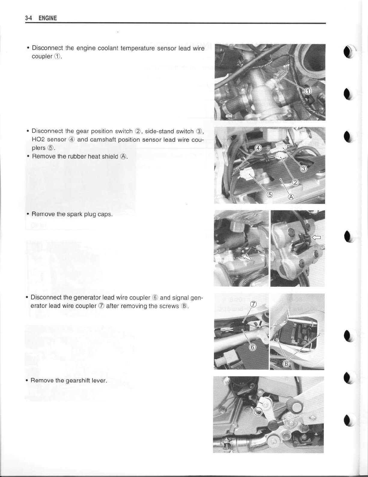
Disconnect the engine coolant temperature sensor lead wire
coupler0
•
Disconnect the gear position switch 02
H02 sensor ® and camshaft position sensor lead wire couplers ($
•
Remove the rubber heat shield
.
,
side-stand switch
OO
,
1
.
OO
.
•
Remove the spark plug caps
•
Disconnect the generator lead wire coupler
erator lead wire coupler 07 after removing the screws
•
Remove the gearshift lever
.
0
and signal gen-
.
OO
.
l
Page 5
~
~
~
~
~
~
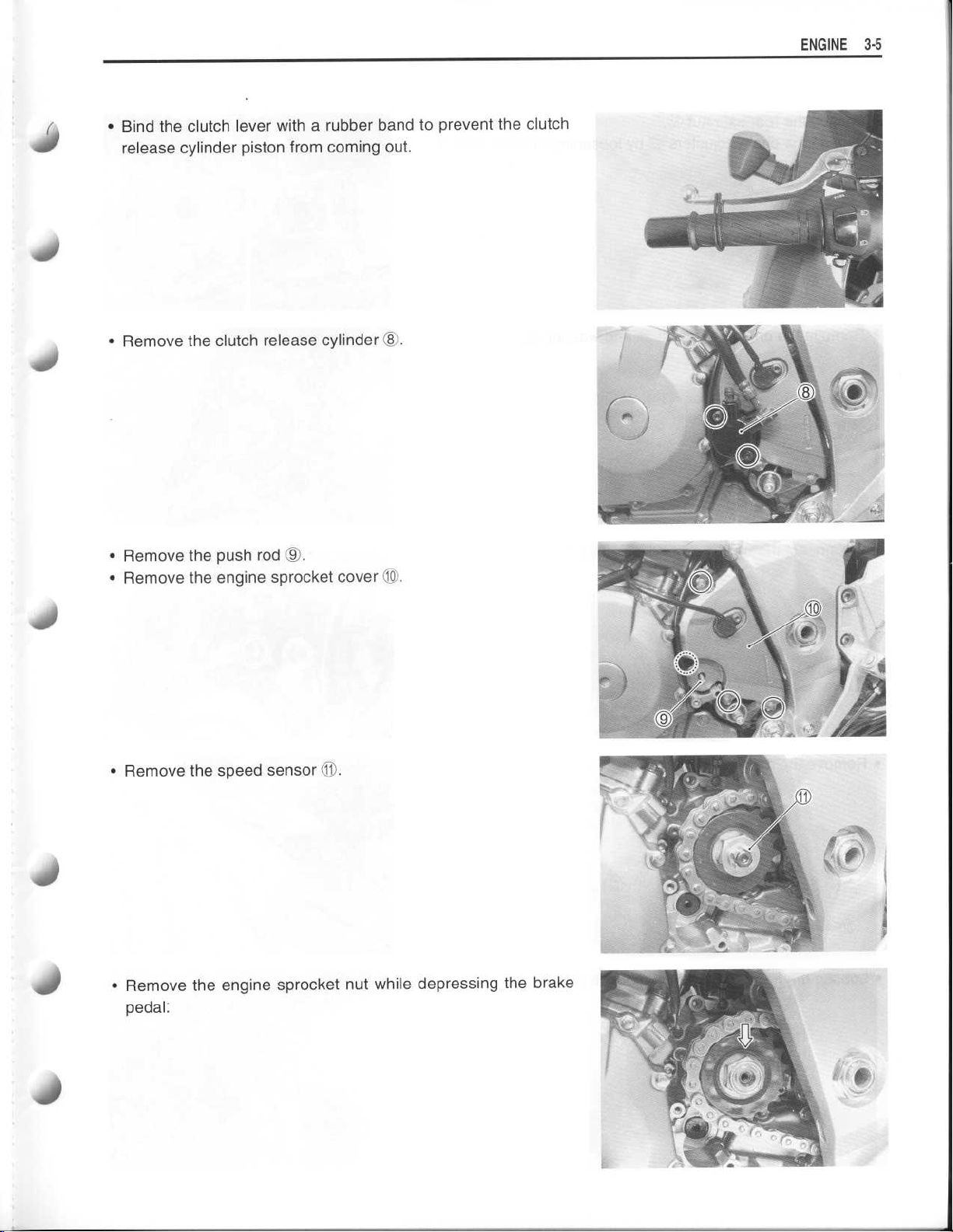
Bind the clutch lever with a rubber band to prevent the clutch
•
release cylinder piston from coming out
Remove the clutch release cylinder ®
•
.
.
ENGINE 3-
5
•
Remove the push rod 09
•
Remove the engine sprocket cover 10
•
Remove the speed sensor 11
Remove the engine sprocket nut while depressing the brake
•
pedal
.
.
.
.
40
Page 6
~
~
~
~
~
~
3-6 ENGINE
•
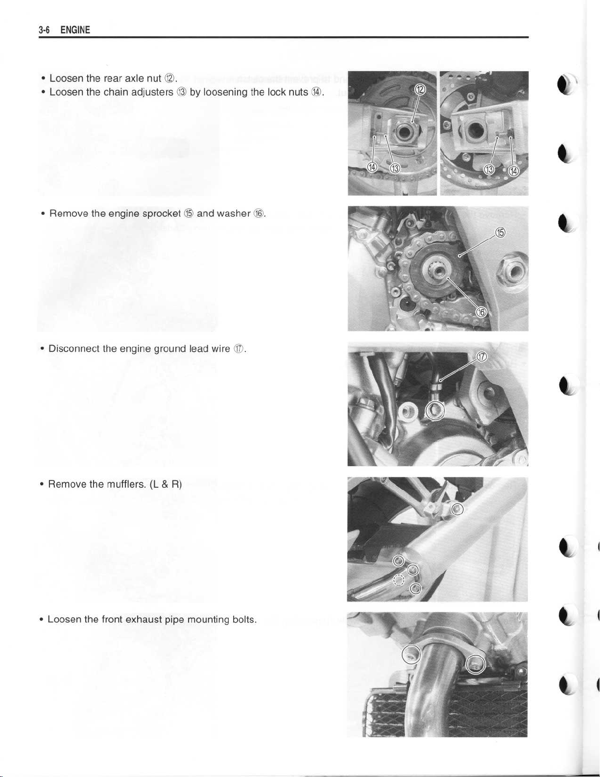
Loosen the rear axle nut 1©
•
Loosen the chain adjusters 13 by loosening the lock nuts
.
(W
.
4
•
Remove the engine sprocket 15 and washer i
.
•
Disconnect the engine ground lead wire i
•
Remove the mufflers
•
Loosen the front exhaust pipe mounting bolts
. (L & R)
.
.
l
Page 7
~
~
~
•
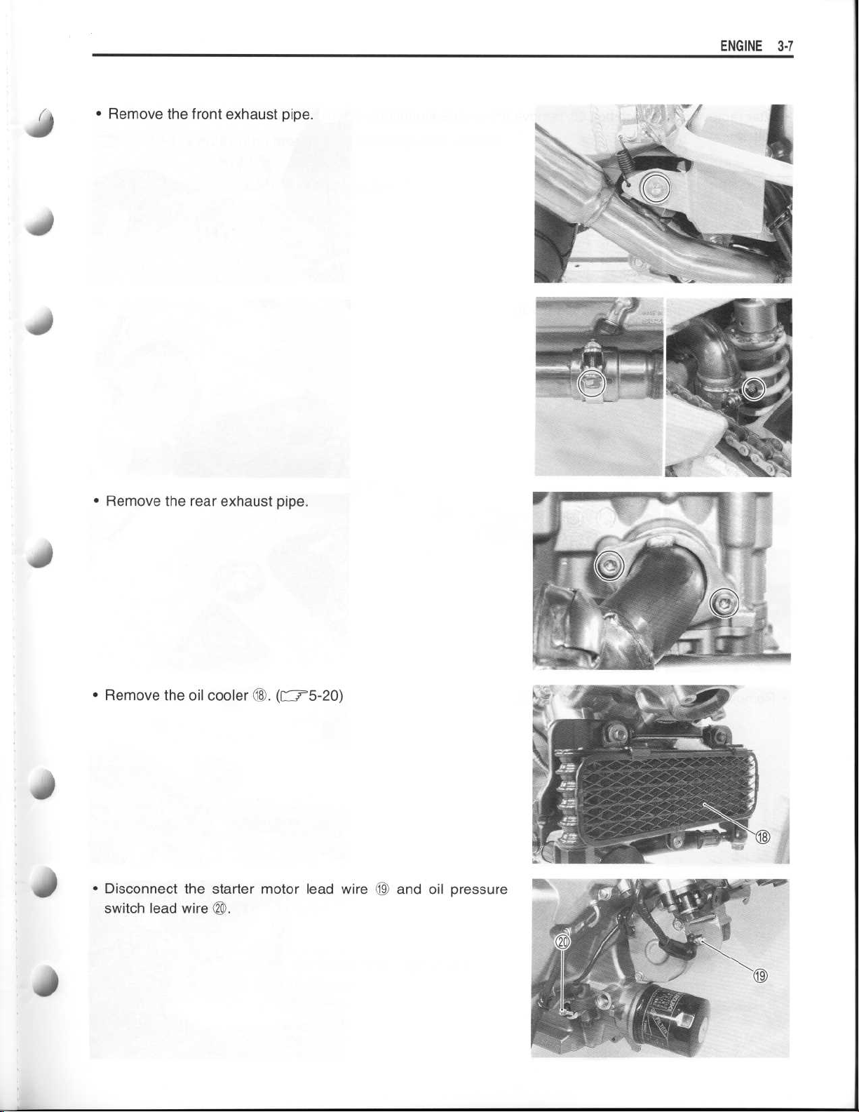
Remove the front exhaust pipe
ENGINE 3-7
.
J
•
Remove the rear exhaust pipe
•
Remove the oil cooler
•
Disconnect the starter motor lead wire 79 and oil pressure
switch lead wire 20
(I
.
.
(f"
.
r5-20)
Page 8
~
~
~
3-8
ENGINE
•
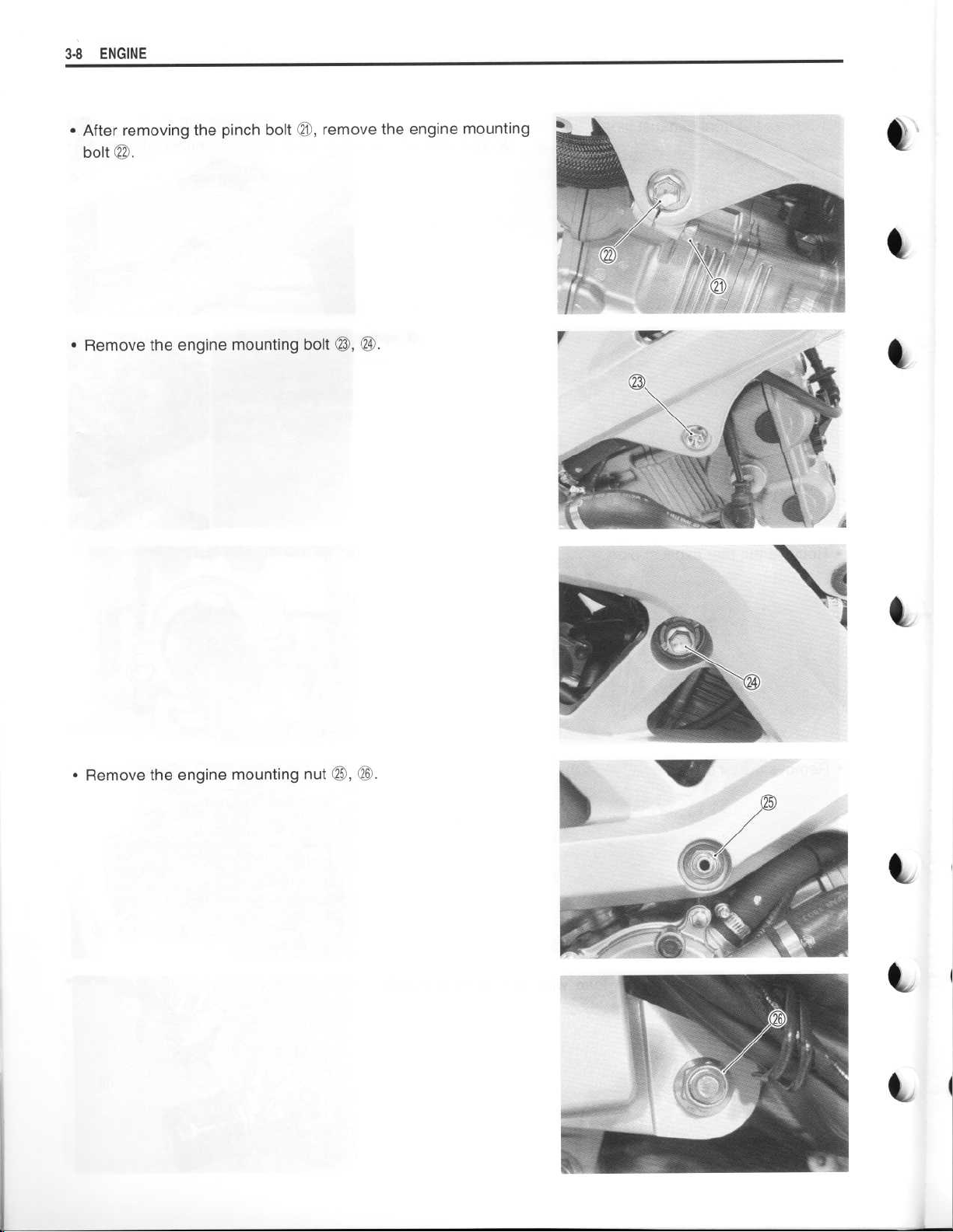
After removing the pinch bolt (3,
bolt
(2
.
Remove the engine mounting bolt 23
•
remove the engine mounting
, (3
.
•
Remove the engine mounting nut
(S,
26
.
I
11
Page 9
~
~
~
~
ENGINE3-9
•
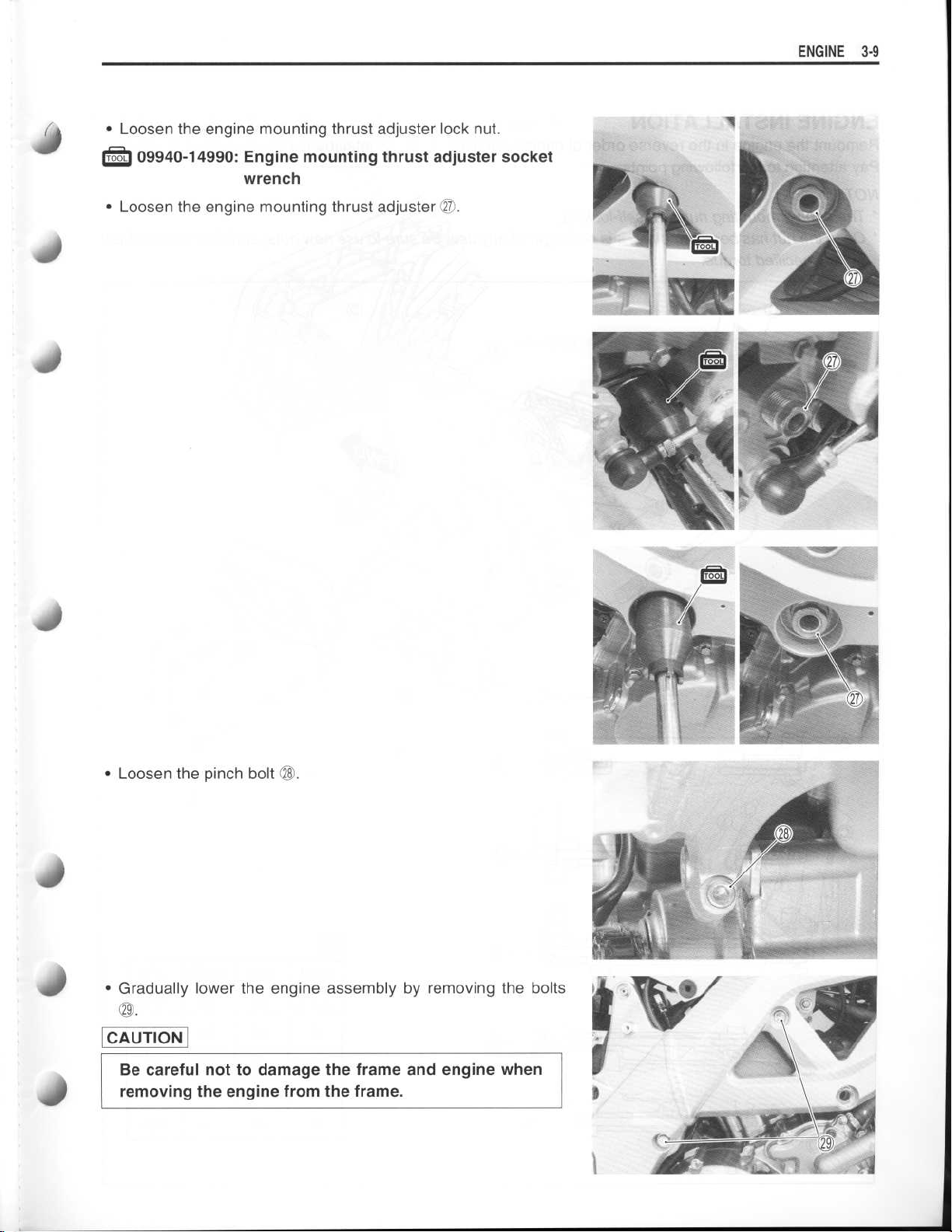
Loosen the engine mounting thrust adjuster lock nut
.
40
09940-14990
•
Loosen the engine mounting thrust adjuster v
: Engine mounting thrust adjuster socket
wrench
.
I'
•
Loosen the pinch bolt 28
•
Gradually lower the engine assembly by removing the bolts
(a
.
CAUTION
Be careful not to damage the frame and engine when
removing the engine from the frame
.
.
Page 10
~
3-10
ENGINE
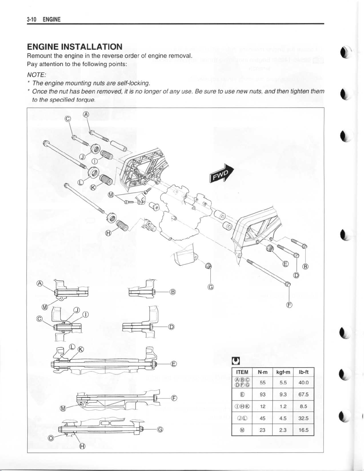
ENGINE INSTALLATION
Remount the engine in the reverse order of engine removal
Pay attention to the following points
NOTE
:
* The engine mounting nuts are self-locking
"
Once the nut has been removed, it is no longer of any use
to the specified torque
.
:
.
.
. Be sure to use new nuts, and then tighten them
r
c
i
A=
' '
ITEM
~©©
OE©
T WK
DJ ©
E
®
N
.m
kgf-m
55 5
®
93 9
12
45
23
1 .2
4
2
.5
.3
.5
.3
lb-ft
40
.0
67
.5
8
.5
32
.5
16
.5
l
Page 11
~
~
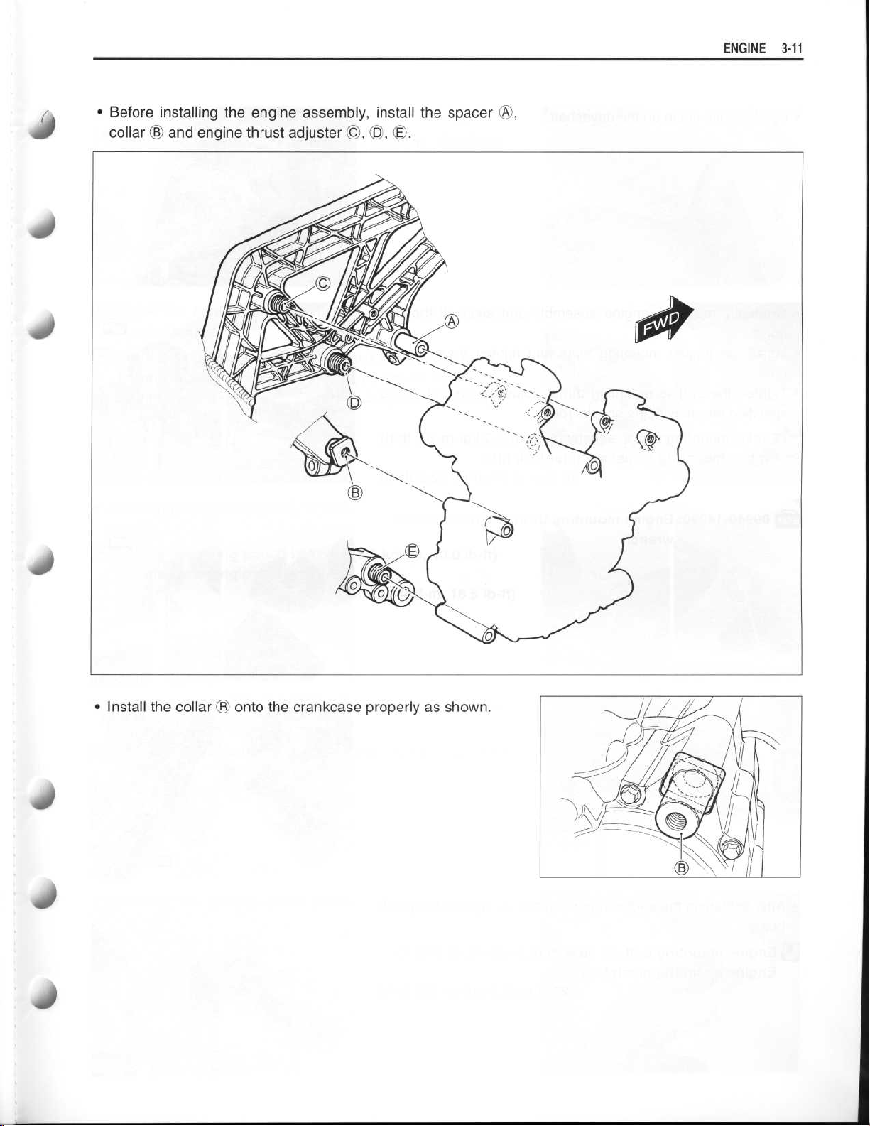
•
Before installing the engine assembly, install the spacer
collar © and engine thrust adjuster
©, O,
OO
.
OO
,
ENGINE 3-
1 1
to
•
Install the collar © onto the crankcase properly as shown
.
Page 12

~
~
~
~
~
~
~
3
-12 ENGINE
•
Put the drive chain on the driveshaft
Gradually raise the engine assembly and align all the bolt
•
holes
.
Install the engine mounting bolts and tighten them tempo-
•
rarily
.
Tighten the engine mounting thrust adjuster lock nut to the
•
specified torque with the special tool
.
.
Engine mounting thrust adjuster
•
Engine mounting thrust adjuster lock nut
09940-14990
: Engine mounting thrust adjuster socket
wrench
: 12 N
.m (1
45 N
.m (4 .5 kgf-m, 32
.2 kgf-m, 8
:
.5 Ib-ft)
.5 Ib-ft)
•
After tightening the engine mounting bolt
bolt ©
.
Engine mounting bolt
•
Engine mounting pinch bolt
OA
:
55 N
.m (5 .5 kgf-m, 40
©
:
23 N
.m (2
tighten the pinch
A),
.3 kgf-m, 6
.0 Ib-ft)
.5 Ib-ft)
Page 13
~
~
~
~
~
~
~
~
ENGINE 3-13
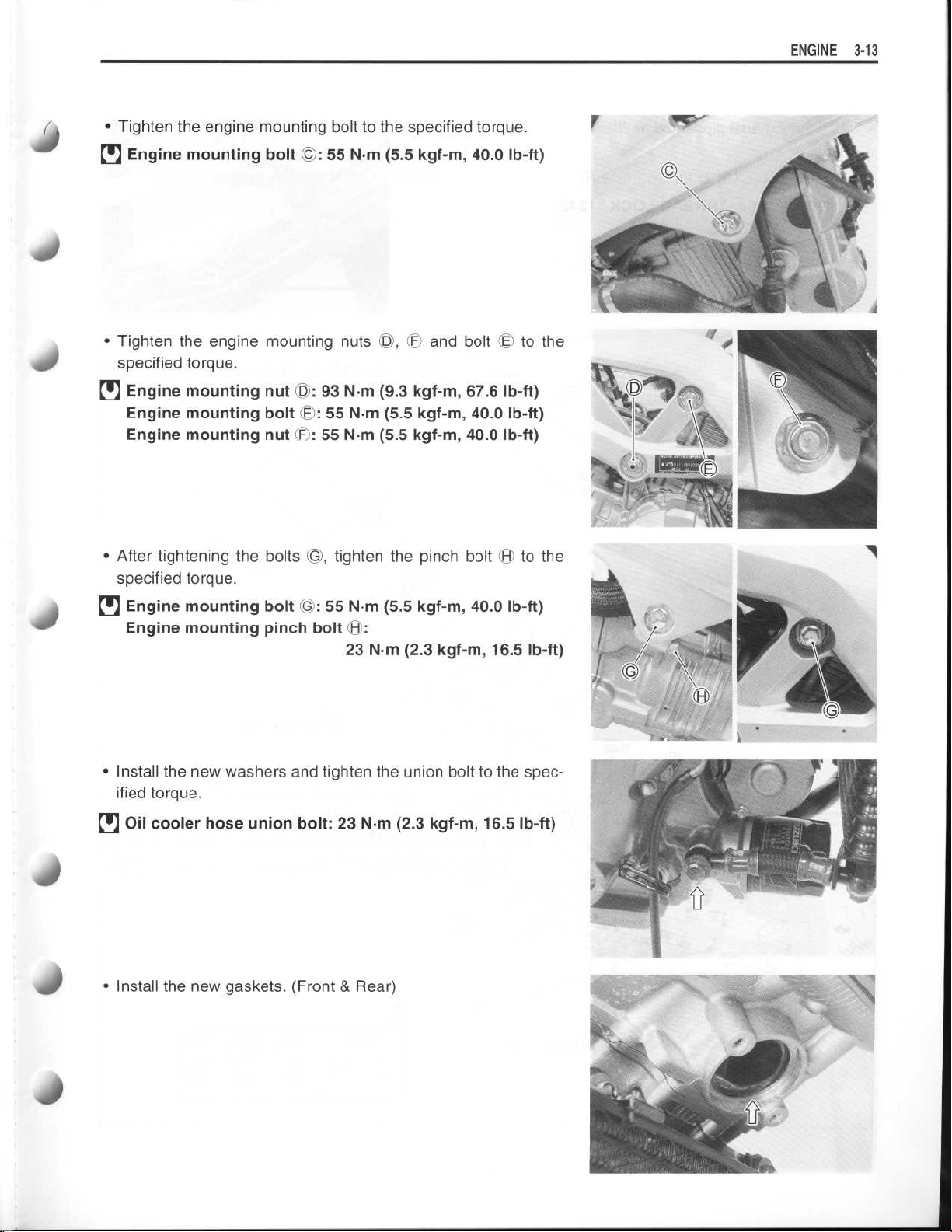
•
Tighten the engine mounting bolt to the specified torque
.
Engine mounting bolt
•
•
Tighten the engine mounting nuts
specified torque
Engine mounting nut(: 93 N-m (9
•
Engine mounting bolt
Engine mounting nut
•
After tightening the bolts ©, tighten the pinch bolt
specified torque
•
Engine mounting bolt
Engine mounting pinch bolt (L
.
.
OO
(F
©
©
:
55 N
:
55 N
:
55 N
:
55 N
23 N
.m (5
.5 kgf-m, 40
OO ,
OO
.3 kgf-m, 67
.m (5
.5 kgf-m, 40
.m (5
.5 kgf-m, 40
.m (5
.5 kgf-m, 40
.m (2
.0 lb-ft)
and bolt (
.6 lb-ft)
.0 lb-ft)
.0 lb-ft)
.0 lb-ft)
.3 kgf-m, 16
.5 lb-ft)
to the
to the
4
•
Install the new washers and tighten the union bolt to the specified torque
Oil cooler hose union bolt
•
•
Install the new gaskets
.
: 23 N
.m (2
.3 kgf-m, 16
. (Front & Rear)
.5 lb-ft)
Page 14
~
3
-14 ENGINE
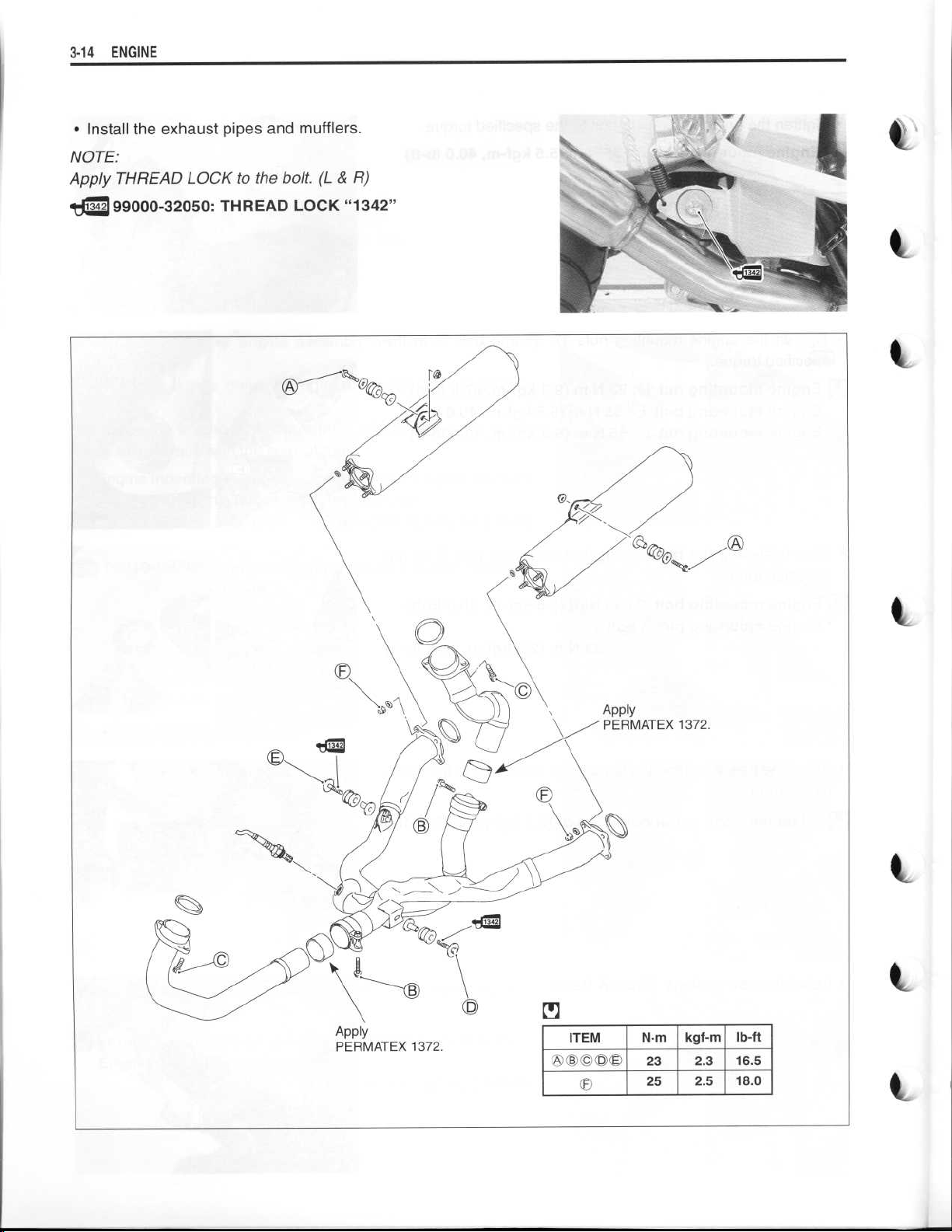
•
Install the exhaust pipes and mufflers
NOTE
:
Apply THREAD LOCK to the bolt
. (L & R)
.
99000-32050
: THREAD LOCK "1342"
I
ITEM
OO©©OO®
N
.m
kgf-m
23
25
lb-ft
2
.3
16
.5
2
.5
18
.0
Page 15
~
~
~
~
~
~
ENGINE 3-15
•
40
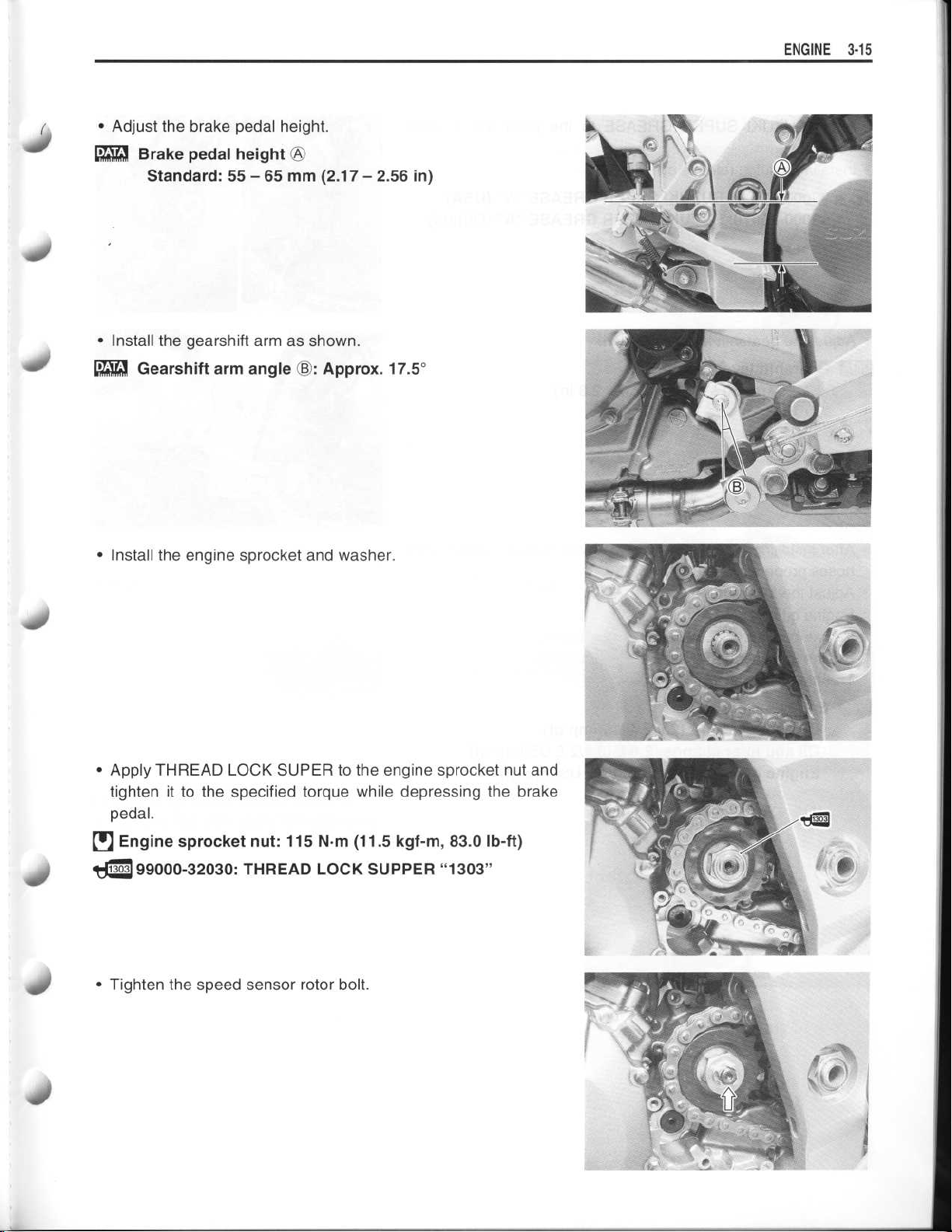
Adjust the brake pedal height
•
Brake pedal height
Standard
•
Install the gearshift arm as shown
•
Gearshift arm angle
: 55 -
65 mm (2
OA
©
.
.17
Approx
:
- 2
.
.56 in)
. 17
.5°
•
Install the engine sprocket and washer
•
Apply THREAD LOCK SUPER to the engine sprocket nut and
tighten it to the specified torque while depressing the brake
pedal
.
Engine sprocket nut
0
99000-32030
•
Tighten the speed sensor rotor bolt
: 115 N
: THREAD LOCK SUPPER "1303"
.m (11
.
.5 kgf-m, 83
.
.0 lb-ft)
40
Page 16
~
~
~
~
~
~
~
~
~
~
~
3
-16 ENGINE
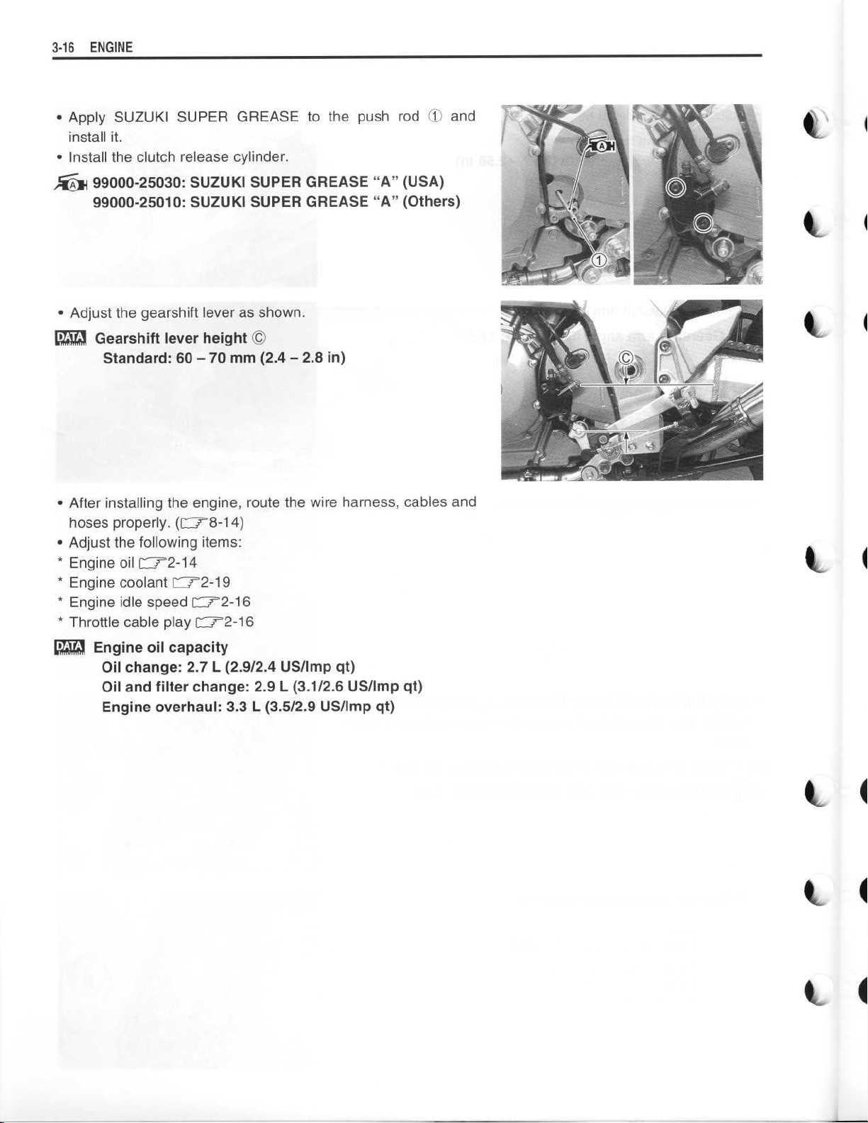
•
Apply SUZUKI SUPER
install it
•
Install the clutch release cylinder
.
GREASE to the push rod 10 and
.
99000-25030
99000-25010
•
Adjust the gearshift lever as shown
•
Gearshift lever height
Standard
•
After installing the engine, route the wire harness, cables and
hoses properly
•
Adjust the following items
•
Engine oil =2-14
•
Engine coolant L7'2-19
•
Engine idle speed C12-16
•
Throttle cable play
•
Engine oil capacity
Oil change
Oil and filter change
Engine overhaul
: SUZUKI SUPER GREASE "A" (USA)
: SUZUKI SUPER GREASE "A" (Others)
.
: 60-70 mm (2.4-
. (Cr8-14)
:
r
-
72-16
: 2
.7 L (2
.9/2
.4 US/Imp qt)
: 2
.9 L (3
: 3
.3 L (3
.8 in)
2
.6 US/Imp qt)
.1/2
.5/2
.9 US/Imp qt)
Page 17
~
~
~
~
ENGINE 3-17
ENGINE DISASSEMBLY
ENGINE TOP SIDE
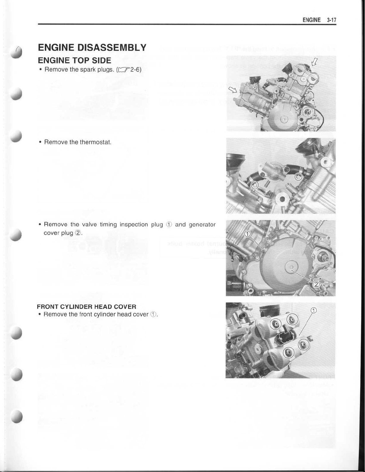
•
Remove the spark plugs.(
r -
7-2-6)
40
•
Remove the thermostat
.
•
Remove the valve timing inspection plugOand generator
cover plug 02
FRONT CYLINDER HEAD COVER
•
Remove the front cylinder head cover J
.
.
Page 18
~
~
~
3-18 ENGINE
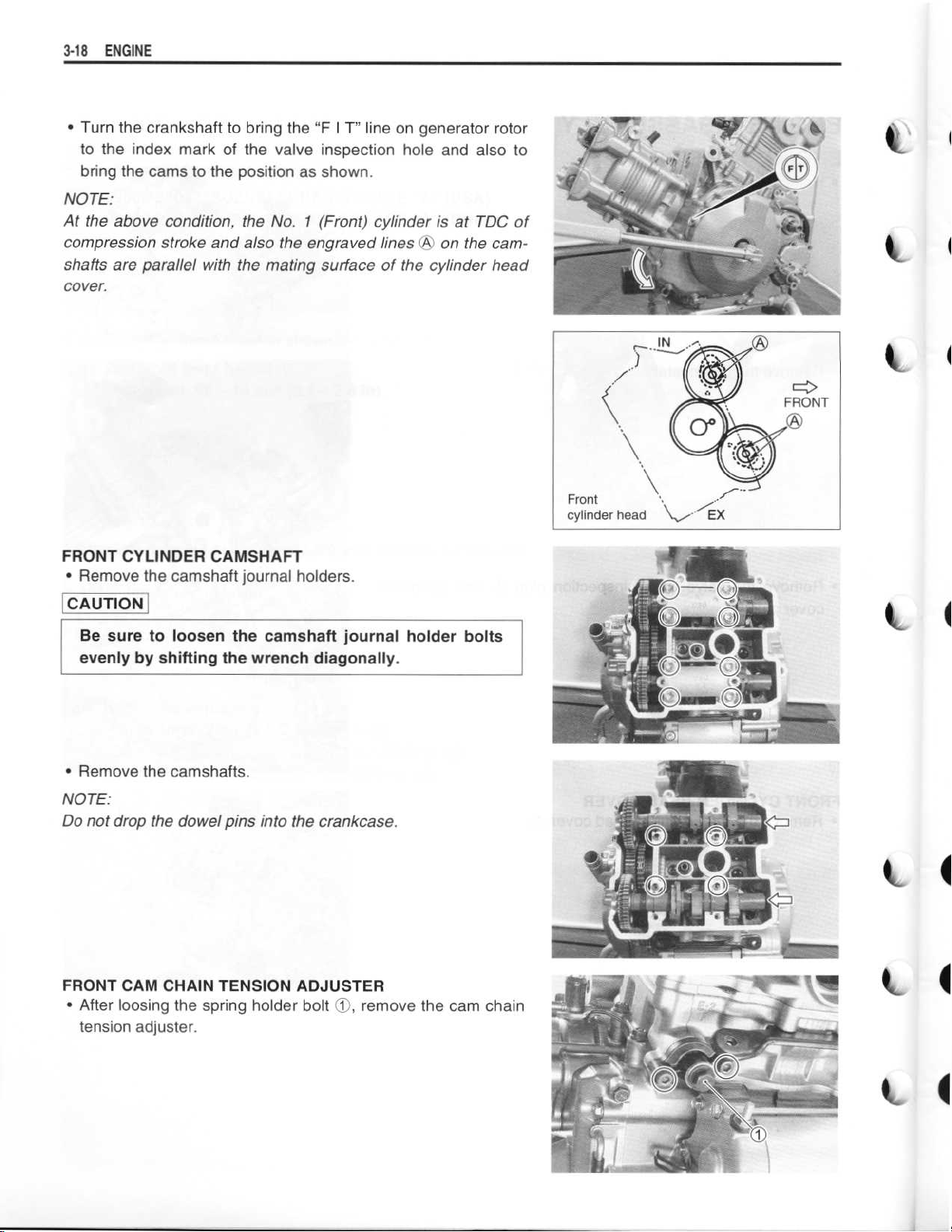
•
Turn the crankshaft to bring the "F I T" line on generator rotor
to the index mark of the valve inspection hole and also to
bring the cams to the position as shown
NOTE
:
At the above condition, the No
compression stroke and also the engraved lines
shafts are parallel with the mating surface of the cylinder head
cover
.
. 1 (Front) cylinder is at TDC of
.
(
on the cam-
FRONT CYLINDER CAMSHAFT
•
Remove the camshaft journal holders
CAUTION
Be sure to loosen the camshaft journal holder bolts
evenly by shifting the wrench diagonally
•
Remove the camshafts
NOTE
:
Do not drop the dowel pins into the crankcase
FRONT CAM CHAIN TENSION ADJUSTER
•
After loosing the spring holder bolt
tension adjuster
.
.
.
.
.
remove the cam chain
O,
Page 19
~
~
~
~
~
~
~
ENGINE 3-19
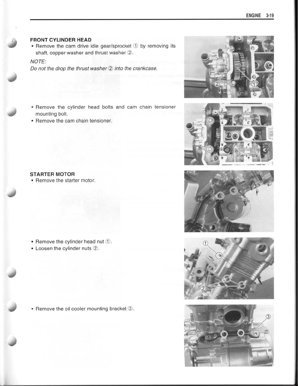
FRONT CYLINDER HEAD
•
Remove the cam drive idle gear/sprocket 90 by removing its
shaft, copper washer and thrust washer
NOTE
:
Do not the drop the thrust washer
OO
OO
.
into the crankcase
.
400
•
Remove the cylinder head bolts and cam chain tensioner
mounting bolt
•
Remove the cam chain tensioner
.
.
STARTER MOTOR
(Z
.
D
.
.
(T
•
Remove the starter motor
•
Remove the cylinder head nut
•
Loosen the cylinder nuts
•
Remove the oil cooler mounting bracket
.
Page 20
~
~
~
~
~
~
~
~
~
3-20 ENGINE
•
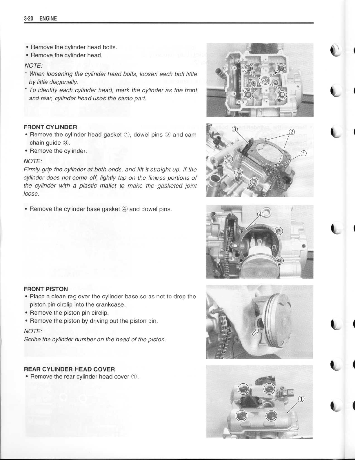
Remove the cylinder head bolts
•
Remove the cylinder head
NOTE
:
.
.
* When loosening the cylinder head bolts, loosen each bolt little
by little diagonally
.
* To identify each cylinder head, mark the cylinder as the front
and
rear,
cylinder head uses the same part
.
FRONT CYLINDER
•
Remove the cylinder head gasketO,dowel pinsOOand cam
chain guide (3
•
Remove the cylinder
NOTE
:
Firmly grip
cylinder does not come off, lightly
.
.
the cylinder at both ends, and lift it
tap
on the finless portions of
straight up
.
If the
the cylinder with a plastic mallet to make the gasketed joint
loose
.
•
Remove the cylinder base gasket ® and dowel pins
.
FRONT PISTON
•
Place a clean rag over the cylinder base so as not to drop the
piston pin circlip into the crankcase
•
Remove the piston pin circlip
•
Remove the piston by driving out the piston pin
NOTE
:
Scribe the
cylinder number on the head of the piston
.
.
.
.
REAR CYLINDER HEAD COVER
•
Remove the rear cylinder head cover 90
.
Page 21
~
~
•
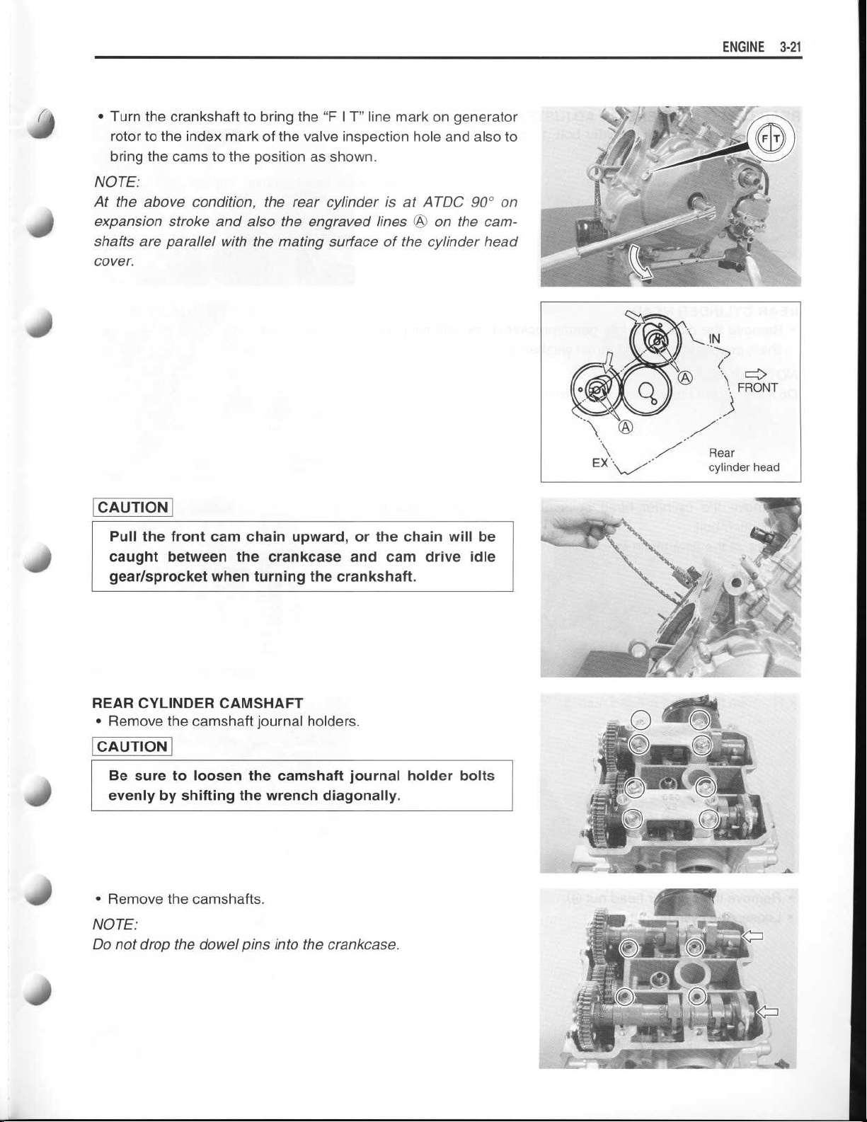
Turn the crankshaft to bring the "F I T" line mark on generator
rotor to the index mark of the valve inspection hole and also to
bring the cams to the position as shown
NOTE
:
At the above condition, the rear cylinder is at ATDC 90° on
expansion stroke and also the engraved lines
shafts are parallel with the mating surface of the cylinder head
cover
.
.
on the cam-
OA
ENGINE
3-21
CAUTION
Pull the front cam chain upward, or the chain will be
caught between the crankcase and cam drive idle
gear/sprocket when turning the crankshaft
REAR CYLINDER CAMSHAFT
•
Remove the camshaft journal holders
CAUTION
Be sure to loosen the camshaft journal holder bolts
evenly by shifting the wrench diagonally
•
Remove the camshafts
.
.
.
.
NOTE
:
Do not drop the dowel pins into the crankcase
.
Page 22
~
~
~
~
~
~
~
3-22 ENGINE
REAR CAM CHAIN TENSION ADJUSTER
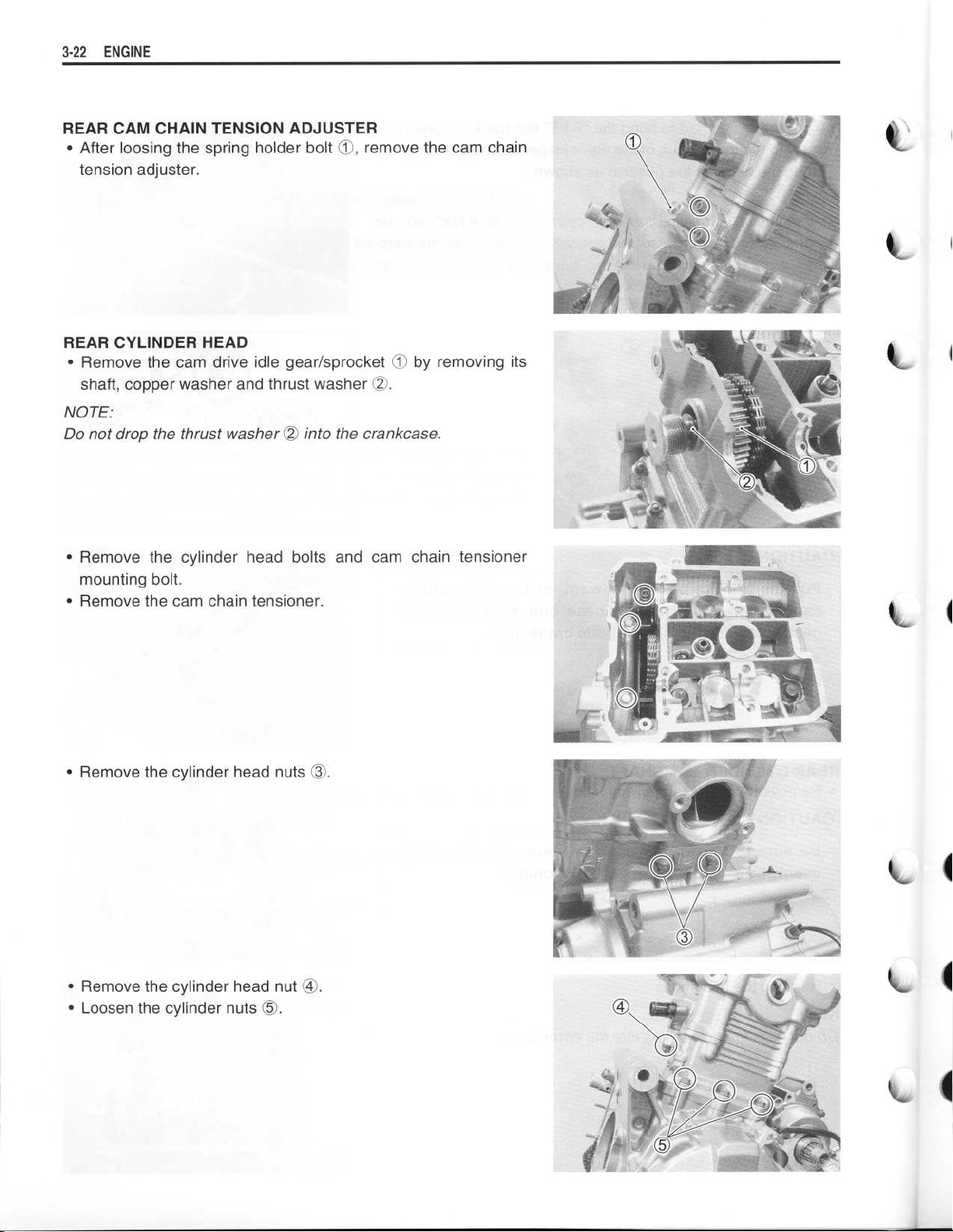
After loosing the spring holder bolt t, remove the cam chain
•
tension adjuster
REAR CYLINDER HEAD
•
Remove the cam drive idle gear/sprocket 1O by removing its
shaft, copper washer and thrust washer 02
NOTE
:
Do not drop the thrust washer
•
Remove the cylinder head bolts and cam chain tensioner
mounting bolt
•
Remove the cam chain tensioner
.
.
2
into the crankcase
.
.
.
c
k-
I
•
Remove the cylinder head nuts (O
•
Remove the cylinder head nut ®
•
Loosen the cylinder nuts 05
)-
.
.
~L
4
Page 23
~
~
~
~
~
~
~
~
•
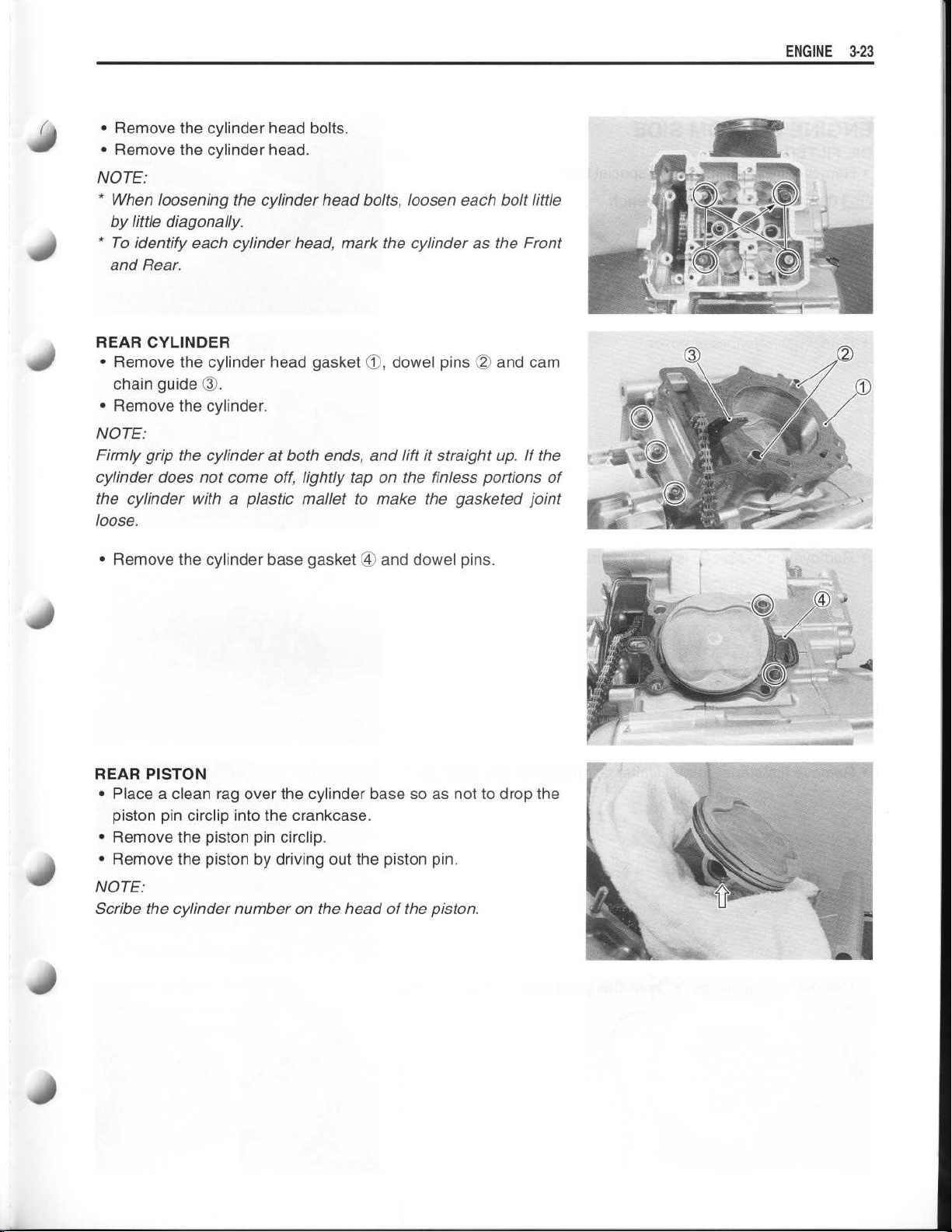
Remove the cylinder head bolts
•
Remove the cylinder head
NOTE
:
* When loosening the cylinder head bolts, loosen each bolt little
by little diagonally
* To identify each cylinder head, mark the cylinder as the Front
and Rear
REAR CYLINDER
•
Remove the cylinder head gasket 90, dowel pins 02 and cam
chain guide
•
Remove the cylinder
NOTE
Firmly grip the cylinder at both ends, and lift it straight up
cylinder does not come off, lightly tap on the finless portions of
the cylinder with a plastic mallet to make the gasketed joint
loose
.
:
.
(1
.
.
.
.
.
. If the
ENGINE
3-23
40
•
Remove the cylinder base gasket ® and dowel pins
REAR PISTON
•
Place a clean rag over the cylinder base so as not to drop the
piston pin circlip into the crankcase
•
Remove the piston pin circlip
•
Remove the piston by driving out the piston pin
NOTE
:
Scribe the cylinder number on the head of the piston
.
.
.
.
.
Page 24
~
~
~
~
~
3-24 ENGINE
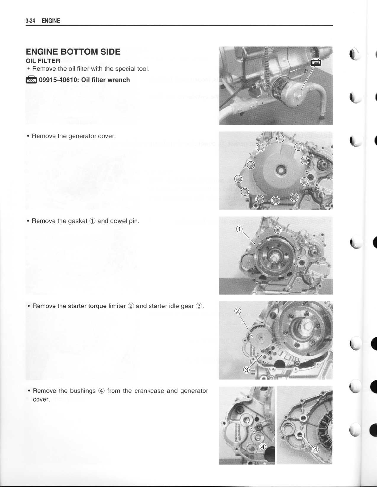
ENGINE BOTTOM SIDE
OIL FILTER
•
Remove the oil filter with the special tool
.
:
09915-40610
•
Remove the generator cover
: Oil filter wrench
.
.
•
Remove the gasket 90 and dowel pin
•
Remove the starter torque limiter
•
Remove the bushings ® from the crankcase and generator
cover
.
.
and starter idle gear 03
O
.
Page 25
~
~
~
~
~
~
ENGINE 3-25
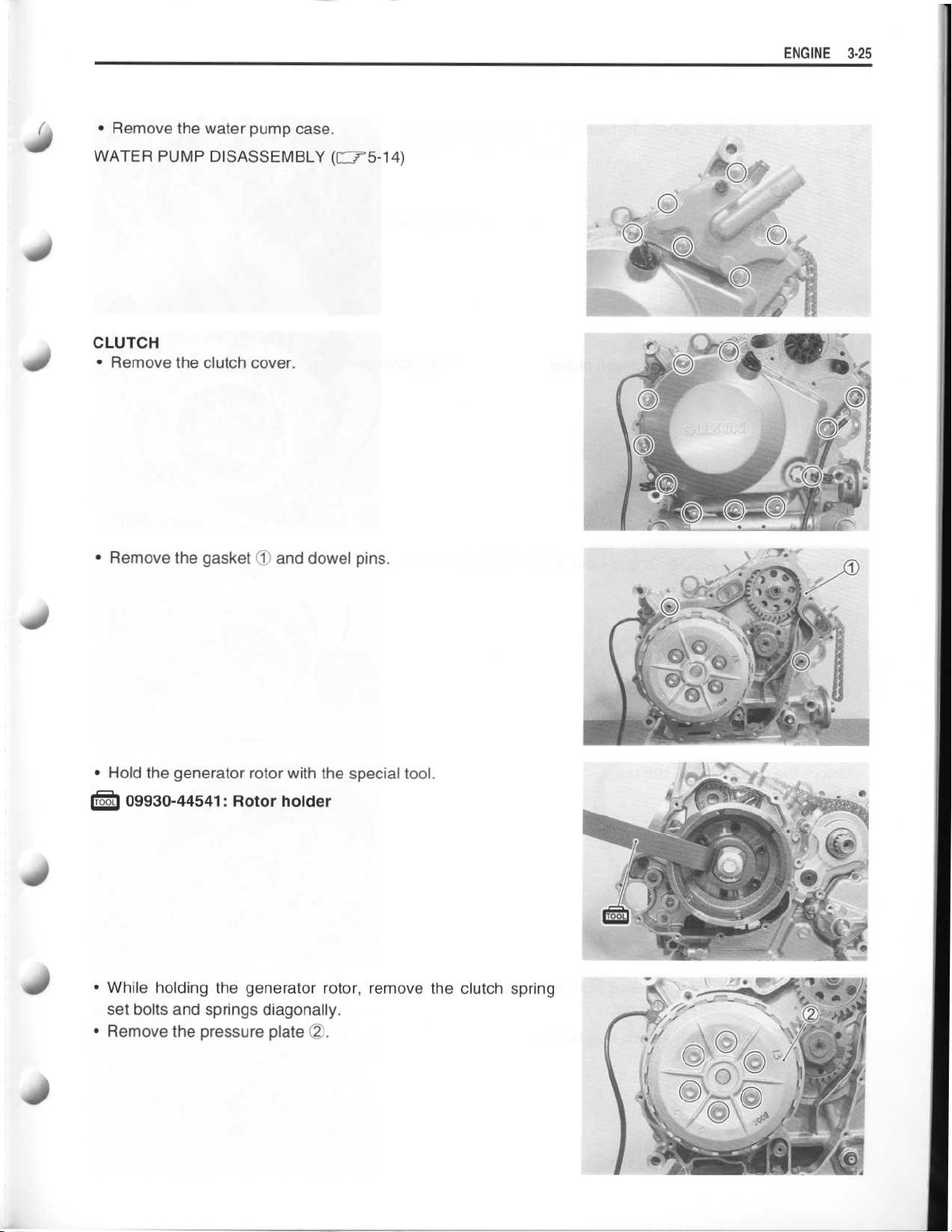
•
Remove the water pump case
.
40
40
WATER PUMP DISASSEMBLY
CLUTCH
•
Remove the clutch cover
•
Remove the gasketDand dowel pins
(r
r5-14)
.
.
S
490
40
•
Hold the generator rotor with the special tool
09930-44541
•
While holding the generator rotor, remove the clutch spring
set bolts and springs diagonally
•
Remove the pressure plate 02
: Rotor holder
.
.
.
40
Page 26
~
~
~
~
~
~
3
-26 ENGINE
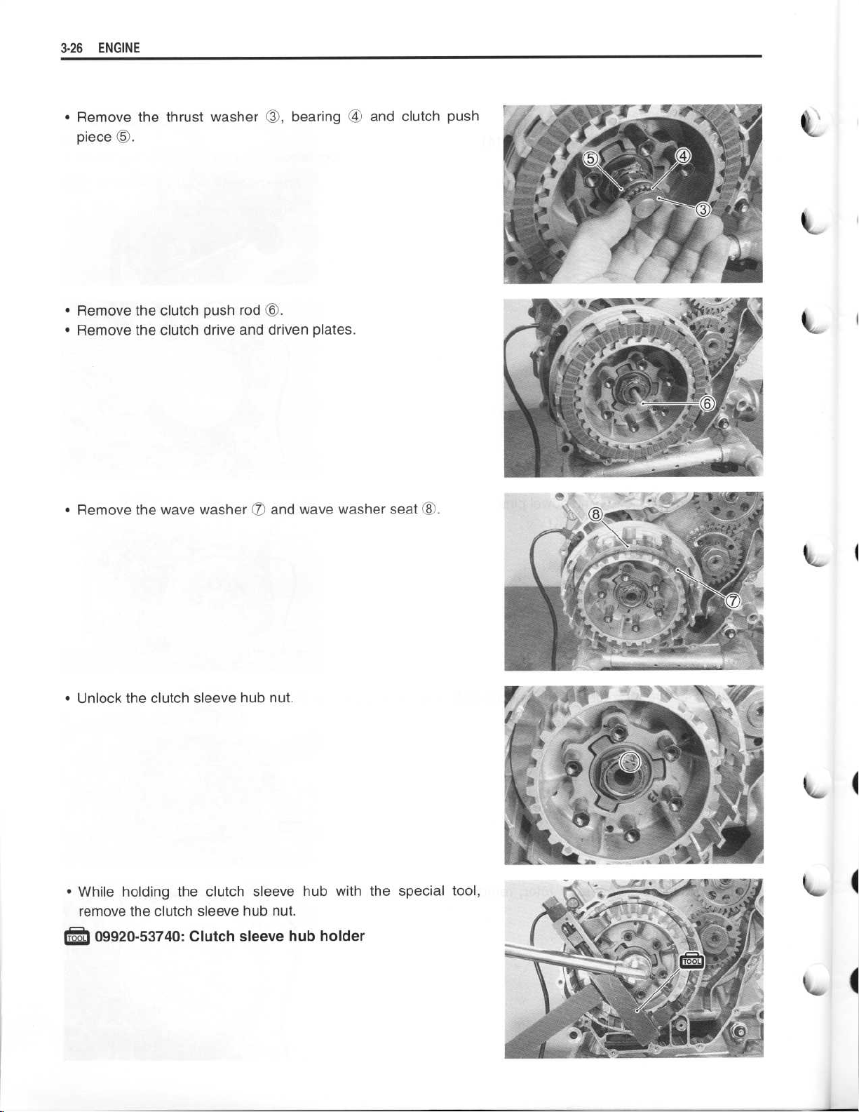
•
Remove the thrust washer ©, bearing ® and clutch push
piece ©
.
I
I
•
Remove the clutch push rod ©
Remove the clutch drive and driven plates
•
.
.
k-
Remove the wave washer (7 and wave washer seat ©
•
•
Unlock the clutch sleeve hub nut
While holding the clutch sleeve hub with the special tool,
•
remove the clutch sleeve hub nut
:
.
09920-53740
: Clutch sleeve hub holder
.
.
.
Page 27
~
~
~
~
~
~
~
ENGINE 3-27
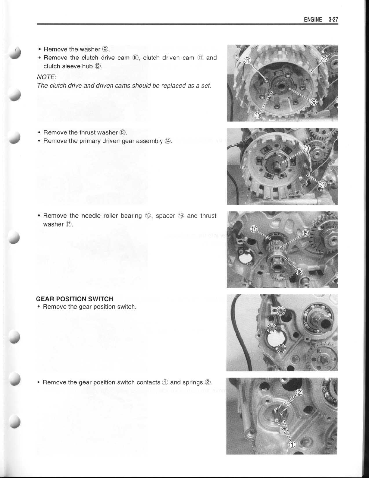
•
40
Remove the washer ©9
•
Remove the clutch drive cam
clutch sleeve hub
NOTE
:
The clutch drive and driven cams should be replaced as a set
•
Remove the thrust washer
•
Remove the primary driven gear assembly 14
(2
.
(2,
clutch driven cam 11 and
.
.
(D
.
.
4-
•
Remove the needle roller bearing 15
washer 17
GEAR POSITION SWITCH
•
Remove the gear position switch
•
Remove the gear position switch contacts ® and springs
.
,
spacer(* and thrust
.
OO
.
Page 28
~
~
~
~
~
3-
2 8
ENGINE
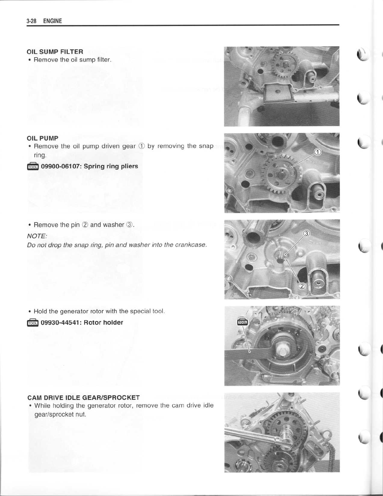
OIL SUMP FILTER
•
Remove the oil sump filter
OIL PUMP
•
Remove the oil pump driven gear 90 by removing the snap
ring
.
. .
09900-06107
: Spring ring pliers
.
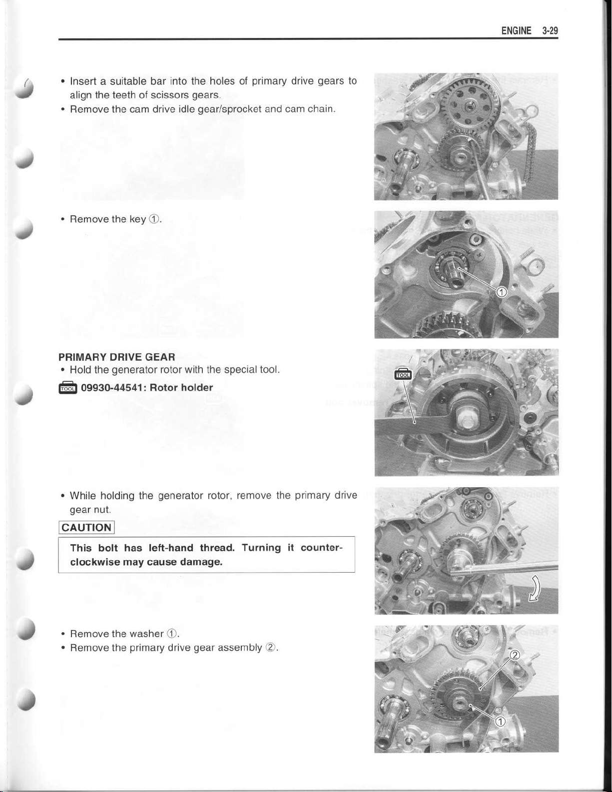
•
Remove the pinOOand washer 03
NOTE
:
Do not drop the snap ring, pin and washer into the crankcase
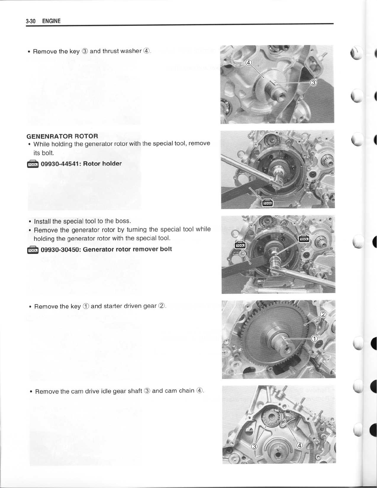
Hold the generator rotor with the special tool
•
09930-44541
CAM DRIVE IDLE GEAR/SPROCKET
•
While holding the generator rotor, remove the cam drive idle
gear/sprocket nut
: Rotor holder
.
.
.
.
Page 29
~
~
~
~
~
~
~
ENGINE 3-29
•
Insert a suitable bar into the holes of primary drive gears to
410
align the teeth of scissors gears
•
Remove the cam drive idle gear/sprocket and cam chain
•
Remove the key
O
.
.
.
PRIMARY DRIVE GEAR
•
Hold the generator rotor with the special tool
09930-44541
•
While holding the generator rotor, remove the primary drive
gear nut
CAUTION
This bolt has left-hand thread
clockwise may cause damage
•
Remove the washer ®
•
Remove the primary drive gear assembly
.
: Rotor holder
. Turning it counter-
.
.
0
.
.
9
Page 30
~
~
~
~
~
~
3-30
ENGINE
•
Remove the key ® and thrust washer ®
.
GENENRATOR ROTOR
While holding the generator rotor with the special tool, remove
•
its bolt
. .
•
•
.
09930-44541
Install the special tool to the boss
Remove the generator rotor by turning the special tool while
holding the generator rotor with the special tool
09930-30450
: Rotor holder
.
.
: Generator rotor remover bolt
k.
I
Remove the key 1O and starter driven gear E
•
Remove the cam drive idle gear shaft ® and cam chain ®
•
.
.
Page 31

~
~
~
~
~
~
GEARSHIFT
•
Remove the gearshift cover
Remove the gasket 1O and dowel pins
•
•
Draw out the gearshift shaft
.
.
OO
.
ENGINE
3-31
•
Remove the gearshift cam plate ®
•
Remove the gearshift cam stopper ®
Remove the engine sprocket spacer O5
•
.
.
.
Page 32

~
~
~
~
~
~
3-32 ENGINE
•
Remove the crankcase bolts
.
Separator the crankcase into 2 parts, right and left with the
•
crankcase separating tool
09920-13120
NOTE
:
•
Fit the crankcase separating tool, so that the tool arms are in
parallel with the side of crankcase
•
The crankshaft and transmission components should remain
in the left crankcase half
When separating the crankcase, tap the end of the counter-
•
shaft with a plastic hammer
•
Remove the dowel pins
: Crankcase separating tool
.
.
.
.
.
Page 33

~
~
~
ENGINE 3-33
•
Remove
gearshift cam ©
•
Remove the countershaft and driveshaft
•
Remove the crankshaft
the
gearshift
fork
shafts
.
.
©,
gearshift
.
forks
(7)
and
40
Page 34

~
~
~
~
~
~
3-34 ENGINE
ENGINE COMPONENTS INSPECTION AND SERVICING
CYLINDER HEAD COVER
DISASSEMBLY
CAUTION
Be sure to identify each removed part as to its loca-
tion, and lay the parts out in groups designated as
"No
. 1", "No
be restored to the original location during assembly
Remove the camshaft position sensor 10
•
Remove the PAIR reed valve cover
•
. 2" "Exhaust", "Intake", so that each will
.
.
OO
.
INSPECTION
Inspect the PAIR reed valve for the carbon deposit
•
If the carbon deposit is found in the reed valve, replace it with
•
a new one
REASSEMBLY
Apply SUZUKI SUPER GREASE to the O-ring and install it
•
99000-25030
99000-25010
•
Apply THREAD LOCK to the thread and install the PAIR reed
valve cover
.
: SUZUKI SUPER GREASE "A" (USA)
: SUZUKI SUPER GREASE "A" (Others)
.
.
.
99000-32050
: THREAD LOCK "1342"
Page 35

~
ENGINE3-35
CAMSHAFT/CYLINDER HEAD
CAUTION
Be sure to identify each removed part as to its loca-
tion, and lay the parts out in groups designated as
"No
go
. 1", "No
be restored to the original location during assembly
. 2", "Exhaust", "Intake", so that each will
.
CAMSHAFT
All camshafts should be checked for runout and also for wear of
cams and journals if the engine has been noted as giving abnor-
mal noise, vibration or lack power output
. Any of these condi-
tions may be caused by camshafts worn down or distorted to the
service limit
The camshafts can be identified by the engraved letter
1O No
No
OO
No
(3
® No
.
.
. 1 (Front) intake camshaft ("INF" and "I"
. 1 (Front) exhaust camshaft ("EXF" and "E"
. 2 (Rear) intake camshaft ("INR" and "I"
. 2 (Rear) exhaust camshaft ("EXR" and "E"
: Intake)
: Exhaust)
: Intake)
: Exhaust)
CAM WEAR
Worn-down cams are often the cause of mistimed valve opera-
tion resulting in reduced power output
.
The limit of cam wear is specified for both intake and exhaust
cams in terms of cam height
S
micrometer
. Replace camshaft if it wears worn down to the limit
which is to be measured with a
(R,
.
Cam height
Service Limit (IN)
09900-20202
: Micrometer (25 - 50 mm)
(EX)
: 37
.48 mm (1
: 36
.08 mm (1
.476 in)
.420 in)
Page 36

~
~
~
3-36 ENGINE
CAMSHAFT JOURNAL WEAR
Determine whether or not each journal is worn down to the limit
by measuring the oil clearance with the camshaft installed in
place
. Use the plastigaugeOto read the clearance at the widest
portion, which is specified as follows
•
Camshaft journal oil clearance
Service Limit (IN&EX)
:
: 0
.150 mm (0
.0059 in)
09900-22301
09900-22302
NOTE
:
Install camshaft journal holder to their original positions
Tighten the camshaft journal holder bolts evenly and diagonally
to the specified torque
Camshaft journal holder bolt
NOTE
:
Do not rotate the camshaft with the plastigauge in place
Remove the camshaft holders, and read the width of the compressed plastigauge with envelope scale
should be taken at the widest part
: Plastigauge
: Plastigauge
.
: 10 N-m (1
.
.0 kgf-m, 7
. This measurement
.
.0 lb-ft)
.
If the camshaft journal oil clearance measured exceeds the limit,
measure the inside diameter of the camshaft journal holder and
outside diameter of the camshaft journal
or the cylinder head depending upon which one exceeds the
specification
Camshaft journal holder I.D.
•
09900-20602
09900-22403
•
Camshaft journal O.D.
09900-20205
.
Standard (IN&EX)
22
.012 - 22
: Dial gauge (1/1 000 mm, 1 mm)
: Small bore gauge (18 -
Standard (IN&EX)
21
.972 -21.993 mm (0
: Micrometer (0
:
.025 mm (0
:
. Replace the camshaft
.8666 - 0
35 mm)
.8650-0
- 25 mm)
.8671 in)
.8659 in)
Page 37

~
CAMSHAFT RUNOUT
Measure the runout with a dial gauge
the runout exceeds the limit
=
Camshaft runout
Service Limit (IN
09900-20607
09900-20701
09900-21304
: Dial gauge (1/100 mm, 10 mm)
: Magnetic stand
-block (100 mm)
: V
.
&
EX)
: 0
CAM GEAR AND AUTOMATIC-DECOMP
Inspect the cam gear teeth for wear and damage
Inspect the automatic-decomp
tion
.
. for damage and smooth opera-
. Replace the camshaft if
.10 mm (0
.004 in)
.
.
If there are unusual, replace the camshaft assembly and cam
chain as a set
.
CAUTION
ENGINE3.
3 7
Do not attempt to disassemble the cam gears and
automatic-decomp
. assembly
. They are unserviceable
.
CAM CHAIN TENSION ADJUSTER
The cam chain tension adjusters are maintained at the proper
cam chain tension automatically
Unlock the ratchet
if it slides smoothly
(k,
and move the push rod © in place to see
. If any stickiness is noted or ratchet mecha-
.
nism is faulty, replace the cam chain tension adjuster assembly
with a new one
.
90 Front cam chain tension adjuster
(2 Rear cam chain tension adjuster
CAM CHAIN GUIDE AND CAM CHAIN TENSIONER
Check the cam chain guide and tensioner for wear and damage
.
If they are found to be damaged, replace them with the new
ones
4
.
O
Front cam chain tensioner
Rear cam chain tensioner
OO
(3 Front and Rear cam chain guide
Page 38

~
~
~
~
~
3-38 ENGINE
CYLINDER HEAD
Remove the pin 10 and O-ring
•
•
Remove the tappets
hand
.
Using special tools, compress the valve spring and remove
•
two cotter halvesOOfrom the valve stem
.
.
09916-14510
09916-14910
09916-84511
O
: Valve lifter
: Valve lifter attachment
: Tweezers
2
.
and shims ® by fingers or magnetic
.
i
•
Remove the valve spring retainer © and valve spring 07
•
Pull out the valve from the other side
.
.
t
. '
Page 39

~
~
•
Remove the oil seals ® and spring seats
CAUTION
O
.
ENGINE3-39
aI
Do not reuse the removed oil seals
CYLINDER HEAD DISTORTION
Decarbonize the combustion chambers
Check the gasketed surface of the cylinder head for distortion
with a straightedge and thickness gauge, taking a clearance
reading at several places indicated
position of the straightedge exceeds the limit, replace the cylin-
der head
VALVE STEM RUNOUT
Support the valve with "V" blocks, as shown, and check its runty
with a dial gauge
The valve must be replaced if the runout exceeds the limit
.
Cylinder head distortion
Service Limit
09900-20803
: 0
.05 mm (0
: Thickness gauge
.
.
.
. If the largest reading at any
.002 in)
.
40
d
Valve stem runout
Service Limit
09900-20607
09900-20701
09900-21304
VALVE HEAD RADIAL RUNOUT
Place the dial gauge at right angles to the valve head face, and
measure the valve head radial runout
If it measures more than the limit, replace the valve
'~Valve head radial runout
Service Limit
09900-20607
09900-20701
09900-21304
: 0
.05 mm (0
: Dial gauge (1/100 mm)
: Magnetic stand
: V-block (100 mm)
: 0
.03 mm (0
: Dial gauge (1/100 mm)
: Magnetic stand
: V
-block (100 mm)
.002 in)
.
.
.001 in)
Page 40

3-40
ENGINE
VALVE FACE WEAR
Visually inspect each valve for wear of its seating face
any valve with an abnormally worn face
decreases as the wear of the face advances
. The thickness
.
. Replace
OT
Measure the thickness and, if the thickness is found to have
been reduced to the limit, replace it
.
Valve head thickness
Service Limit
09900-20101
: 0
: Vernier calipers
OT
.5 mm (0
.02 in)
VALVE STEM DEFLECTION
Lift the valve about 10 mm (0
.39 in) from the valve seat
.
Measure the valve stem deflection in two directions, "X" and "Y",
perpendicular to each other, by positioning the dial gauge as
shown
. If the deflection measured exceeds the limit, (see below)
then determine whether the valve or the guide should be
replaced with a new one
.
Valve stem deflection (IN&EX)
Service Limit
09900-20607
09900-20701
: 0
.35 mm (0
.014 in)
: Dial gauge (1/100 mm)
: Magnetic stand
VALVE STEM WEAR
If the valve stem is worn down to the limit, as measured with a
micrometer, where the clearance is found to be in excess of the
limit indicated, replace the valve
then replace the guide
recheck the clearance
. After replacing valve or guide, be sure to
.
; if the stem is within the limit,
Valve stem O.D.
Standard (IN):5
09900-20205
NOTE
:
If
valve
(EX):5
: Micrometer (0 - 25 mm)
guides havetobe
.475
- 5
.455
.490 mm (0
- 5
.470 mm (0
.2156-0
.2148-0
.2161 in)
.2154 in)
removed for replacement after
inspecting related parts, carry out the steps shown in valve
guide servicing
.
Page 41

~
~
~
~
~
VALVE GUIDE SERVICING
Using the valve guide remover, drive the valve guide out
•
toward the intake or exhaust camshaft side
.
.
09916-44910
NOTE
:
•
Discard the removed valve guide subassemblies
Only oversized valve guides are available as replacement
•
. (Part No
parts
•
Re-finish the valve guide holes in cylinder head with the
reamer and handle
09916-34580
09916-34542
: Valve guide remover/installer
. 111 15-32E70)
.
: Valve guide reamer
: Reamer handle
.
.
ENGINE3-4
1
S
S
•
Oil the stem hole, too, of each valve guide and drive the guide
into the guide hole with the valve guide installer and attachment
.
09916-44910
09916-53340
CAUTION
Failure to oil the valve guide hole before driving the
new guide into place may result in a damaged guide or
head
.
•
After fitting the valve guides, re-finish their guiding bores with
the reamer
09916-34550
09916-34542
NOTE
:
Insert the reamer from the combustion chamber and always turn
the reamer handle clockwise
VALVE SEAT WIDTH
•
Coat the valve seat uniformly with Prussian blue
and tap the coated seat with the valve face in a rotating man-
ner, in order to obtain a clear impression of the seating con-
tact
. In this operation, use the valve lapper to hold the valve
head
.
: Valve guide remover/installer
: Attachment
. Be sure to clean and oil the guides after reaming
: Valve guide reamer
: Reamer handle
.
. Fit the valve
.
im
Page 42

~
~
3-42 ENGINE
•
The ring-like dye impression left on the valve face must be
continuous without any break
ring, which is the visualized seat "width", must be within the
following specification
L 1
Valve seat width
Standard
. .
09916-10911
If either requirement is not met, correct the seat by servicing is
as follows
VALVE SEAT SERVICING
The valve seats for both intake and exhaust valves are
machined to four different angles
cut 45°
:
.)
: 0
:
.9 -1.1 mm (0
: Valve lapper set
. In addition, the width of the dye
.035-0
. (The seat contact surface is
.043 in)
INTAKE
45
0
60°
15°
30°
NOTE
:
The valve seat contact area must be inspected after each cut
09916-21111
09916-24210
09916-24480
09916-24810
09916-27710
•
Insert the solid pilot with a slight rotation
snugly
•
Using the 45° cutter, descale and clean up the seat with one
or two turns
•
Inspect the seat by the previously described seat width measurement procedure
seat conditioning with the 45° cutter is required
NOTE
:
Cut only the minimum amount necessary from the seat to prevent the possibility of the tappet shim replacement
N-615 or N-626 N-615 or N-626
N-211 N-211
_
N-626
: Valve seat cutter set
: Valve seat cutter (N-615)
: Solid pilot (N-140-5
: Valve seat cutter (N-626)
: Valve seat cutter (N-211)
. Install the 45° cutter, attachment and T-handle
.
. If the seat is pitted or burned, additional
EXHAUST
_
N-615
.
.5)
. Seat the pilot
.
.
.
Page 43

If the contact area is too high on the valve, or if it is too wide, use
the 150/600cutters (for exhaust side) and 30°/60° cutters (for
intake side) to lower and narrow the contact area
.
ENGINE 3-43
1
40
If the contact area is too low or too narrow, use the 45° cutter to
raise and widen the contact area
•
After the desired seat position and width is achieved, use the
.
Contact area too low and too
narrow on face of valve
45° cutter very lightly to clean up any burrs caused by the previous cutting operations
.
CAUTION
DO NOT use lapping compound after the final cut is
made
. The finished valve seat should have a velvety
smooth finish and not a highly polished or shiny fin-
ish
.
This will provide a soft surface for the final seating of
the valve which will occur during the first few seconds
of engine operation
.
40
40
•
Clean and assemble the head and valve components
intake and exhaust ports with gasoline to check for leaks
. Fill the
. If
any leaks occur, inspect the valve seat and face for burrs or
other things that could prevent the valve from sealing
.
A WARNING
Always use extreme caution when handling gasoline
NOTE
:
.
After servicing the valve seats, be sure to check the tappet
.
(r7
clearance after the cylinder head has been reinstalled
2-8)
Page 44

~
3-44 ENGINE
VALVE SPRING
The force of the coil spring keeps the valve seat tight
ened spring results in reduced engine power output, and often
account for the chattering noise coming from the valve mechanism
Check the valve springs for proper strength by measuring their
free length and also by the force required to compress them
the spring length is less than the service limit, or if the force
required to compress the spring does not fall within the range
specified, replace it
(
Valve spring free length (IN&EX)
Service Limit
Valve spring tension (IN & EX)
Standard
.
: 41
.2 mm (1
: 197 - 227 N/35
(20
.1 -23.1 kgf/35
.62 in)
.6 mm
.6 mm, 44.3-51.0 lbs/1
. Weak-
. If
L
.40 in)
09900-20102
CAM DRIVE IDLE GEAR/SPROCKET THRUST CLEARANCE
Install the cam drive idle gear/sprocket
washer (3 and thrust washer ® to each cylinder head
the shaft02to the specified torque
measure the thrust clearance between the cylinder head and the
thrust washer
90
Cam drive idle gear/sprocket thrust clearance
Standard
: Vernier calipers
®
.
: 0
.15 -
.29 mm (0
0
(1),
its shaft
. Use a thickness gauge to
.006
.011 in)
- 0
02,
copper
. Tighten
Cam drive idle gear/sprocket shaft
0
40 N
09900-20803
: Thickness gauge
:
.m (4 .0 kgf-m, 29
.0 lb-ft)
Re
Page 45

~
~
~
~
~
If the thrust clearance exceeds the standard range, adjust the
thrust clearance by the following procedures
•
Remove the thrust washer, and measure its thickness with a
micrometer
•
Change the thrust washer with the other washer if the thrust
clearance is incorrect
•
Perform the thrust clearance measurement described above
once again checking to make sure it is within standard
09900-20205
.
: Micrometer (0
Color/Mark
(Part No
(09181-15182)
Yellow
(09181-15181)
Light blue
(09181-15176)
Light green
(09181-15172)
Brown
(09181-15166)
"J" mark
(09181-15164)
.)
Blue
.
- 25 mm)
Thrust washer thickness E
:
1
.38-1
(0
.054-0.056)
1
.28-1
(0
.050
-0
1
.18-1
(0
.046-0
1
.08-1
(0
.043-0
0
.98-1
(0
.039-0
0
.88-0
(0
.035
- 0
Unit
.42
.32
.052)
.22
.048)
.12
.044)
.02
.040)
.92
.036)
.
: mm (in)
ENGINE
3-45
40
CYLINDER HEAD REASSEMBLY
•
Install the valve spring seats
•
Apply oil to each oil seal, and press-fit them into position with
the valve guide installer
09916-44910
CAUTION
Do not reuse the removed oil seals
•
Insert the valves, with their stems coated with molybdenum oil
solution all around and along the full stem length without any
break
.
CAUTION
When inserting each valve, take care not to damage
the lip of the oil seal
MOLYBDENUM OIL SOLUTION
-a
: Valve guide remover/installer
.
.
.
.
Page 46

~
~
~
~
~
3- 46ENGINE
•
Install the valve spring with the small-pitch portion
cylinder head
Large-pitch portion
©
:
•
Put on the valve spring retainer, and using the valve lifter,
press down the spring, fit the cotter halves to the stem end,
and release the lifter to allow the cotter 1~ to wedge in
between retainer and stem
the cotter fits snugly into the groove © in the stem end
~ •
09916-14510
09916-14910
09916-84511
.
. Be sure that the rounded lip © of
: Valve lifter
: Valve lifter attachment
: Tweezers
OO
.
facing
I
(D C
~
CAUTION
Be sure to restore each spring and valve to their original positions
•
Install the tappet shim and tappet to their original position
NOTE
:
•
Apply engine oil to the shim and tappet before fitting them
•
When seating the tappet shim, be sure the figure printed sur-
face faces the tappet
•
Apply engine oil to the 0-ring and install it
.
.
.
.
.
I
Page 47

~
~
~
~
~
•
Install the pin (
INTAKE PIPE/WATER UNION
•
Remove the intake pipe
.
.
ENGINE
3-47
.0
•
Remove the water union
•
When installing the intake pipe, apply grease to the 0-ring
NOTE
:
"UP" mark faces upward
99000-25030
99000-25010
CAUTION
Use the new 0-ring to prevent air from sucking
through the joint
•
Apply engine coolant to the new 0-ring and install the water
union
.
: SUZUKI SUPER GREASE "A" (USA)
: SUZUKI SUPER GREASE "A" (Others)
.
.
.
.
Page 48

~
~
~
~
3-48
ENGINE
CYLINDER/PISTON INSPECTION
CYLINDER DISTORTION
Check the gasketed surface of the cylinder for distortion with a
straightedge and thickness gauge, taking a clearance reading at
several places as indicated
of the straightedge exceeds the limit, replace the cylinder
•
Cylinder distortion
Service Limit
.
•
09900-20803
CYLINDER BORE
Inspect the cylinder wall for any scratches, nicks or other dam-
. Measure the cylinder bore diameter at six places
age
•
Cylinder bore
Standard
: Thickness gauge
: 98
. If the largest reading at any position
.
.05 mm (0
: 0
.000 - 98
.002 in)
.015 mm (3
.8583 - 3
.8589 in)
.
k.
PISTON DIAMETER
Using a micrometer, measure the piston outside diameter at
10 mm (0
less than the limit, replace the piston
•
.
.
PISTON-TO-CYLINDER CLEARANCE
As a result of the previous measurement, if the piston to cylinder
clearance exceeds the following limit, replace both cylinder and
piston
•
.4 in) from the piston skirt end
Piston diameter
Service Limit
09900-20204
.
Piston to cylinder clearance
Service Limit
: 97
.880 mm (3
: Micrometer (75 - 100 mm)
: 0
.12 mm (0
. If the measurement is
.
.8535 in)
.0047 in)
Page 49

~
~
~
~
~
PISTON RING TO GROOVE CLEARANCE
Using a thickness gauge, measure the side clearances of the
1st and 2nd rings
replace both piston and piston rings
(
Piston ring to groove clearance
Service Limit (1st)
. If any of the clearances exceeds the limit,
.
:
0
(2nd)
.18 mm (0
:0.15 mm (0
.0071 in)
.0059 in)
O
ENGINE 3-
4 9
•
Piston ring groove width
Standard (1st):0
(2nd)
(Oil)
•
Piston ring thickness
Standard (1st):0
(2nd):0
09900-20803
09900-20205
PISTON RING FREE END GAP AND PISTON RING END GAP
Before installing piston rings, measure the free end gap of each
ring using vernier calipers
measure each ring end gap using a thickness gauge
If any ring has an excess end gap, replace the ring
•
Piston ring free end gap
Service Limit (1st):7
: Thickness gauge
: Micrometer (0
.93 - 0
1
.55-1
: 1
.01 - 1
: 2
.51 -2.53 mm
.86
1
.38
.97-0
. Next, fit the ring in the cylinder, and
(2nd):8
.95 mm
(0
.0366-0
.57
mm
(0
.0610
.03 mm
(0
.0398-0
(0
.0988-0
.91 mm (0
- 0
1
.40 mm (0
-
.99 mm (0
- 25 mm)
.0 mm (0
.1 mm (0
.0374 in)
- 0 .0618 in)
.0406 in)
.0996 in)
.034 -0.036 in)
.054-0
.038-0
.
.
.28 in)
.32 in)
O
O3
.055 in)
.039 in)
10
i
H
l
O
li®
1
09900-20101
: Vernier caliper
Page 50

3-50 ENGINE
Piston ring end gap
Service Limit (1st):0
(2nd)
09900-20803
PISTON PIN AND PIN BORE
Using a small bore gauge, measure the piston pin bore inside
diameter, and using a micrometer, measure the piston pin outside diameter . If the difference between these two measure-
ments is more than the limits, replace both piston and piston pin
Piston pin bore I.D.
Service limit
09900-20602
09900-22403
: Thickness gauge
: 22
.030 mm (0
: Dial gauge (1/1 000 mm, 1 mm)
: Small bore gauge (18-35 mm)
.7 mm (0
.7 mm (0
:
0
.03 in)
.03 in)
.
.8673 in)
L
Using a micrometer, measure the piston pin outside diameter at
three positions
Piston pin O.D.
Service Limit
09900-20205
.
: 21
.980 mm (0
: Micrometer (0 -
.8654 in)
25 mm)
CON ROD/CRANKSHAFT
CONROD SMALL END I
Using a small bore gauge, measure the inside diameter of the
conrod small end
Conrod small end I.D.
Service Limit
09900-20602
09900-22403
If the inside diameter of the conrod small end exceeds the limit,
replace the conrod
.
: Dial gauge (1/1 000 mm, 1 mm)
: Small bore gauge (18 -
.
.D
.
: 22
.040 mm (0
.8677 in)
35 mm)
Page 51

~
~
~
~
~
~
~
CONROD BIG END SIDE CLEARANCE
Check the conrod side clearance by using a thickness gauge
the clearance exceeds the limit, replace conrod or crankshaft
•
Conrod big end side clearance
Service Limit
09900-20803
Conrod big end width
[
Standard
•
Crank pin width
Standard
09900-20205
: 0
.50 mm (0
: Thickness gauge
: 21
.95 - 22
.17 -
44
: 44
: Micrometer (0
.020 in)
.00 mm (0
.22 mm (1
- 25 mm)
.864 -0.866 in)
.739-1
.741 in)
. If
.
OWN
ENGINE3-5
1
S
CONROD-CRANK PIN BEARING INSPECTION
•
Loosen the bearing cap bolts, and tap the bearing cap bolt
lightly with plastic hammer to remove the bearing cap
CAUTION
Never reuse the bearing cap bolt
Remove the conrods, and mark them to identify the cylinder
•
position
Inspect the bearing surfaces for any sign of fusion, pitting,
•
burn, or flaws
bearings
CONROD-CRANK PIN BEARING SELECTION
Place plastigauge axially on the crank pin avoiding the oil
•
hole, at TDC or BDC side as shown in the illustration
•
Tighten the bearing cap bolts as the specified manner
.
. If any, replace them with a specified set of
.
.
.
.
.
09900-22301
09900-22302
NOTE
:
Never rotate the crankshaft or conrod when a piece of plastigauge is in the clearance
: Plastigauge
: Plastigauge
.
Page 52

~
~
~
~
3-52 ENGINE
Remove the caps and measure the width of compressed plas-
•
tigauge
taken at the widest part
•
If oil clearance exceeds the service limit, select the specified
bearings from the bearing selection table
•
Check the corresponding conrod I
«2„
•
Check the corresponding crank pin O
"2" or "3" stamped on the left crank web
Bearing selection table
with envelope
Con rod big end oil clearance
Service Limit
scale
.
: 0
.080 mm (0
. This measurement should be
.0031 in)
.D
. code number
.D
.
"1" or
OO,
. code number ©,
.
"1",
Crank pin O.D.
Code
Con rod I
code
[
Conrod big end I.D. specification
. D
.
C
Conrod big end oil clearance
Standard
Code
1
2 Black
: 0
.040 -0.064 mm (0
OO
1
2
1
Green
48
(1
48
(1
I
.D
2 3
Black
Brown
.0016
- 0
. specification
.000-48
.8898
.008 -48.016 mm
.8900 -1.8904 in)
.008 mm
- 1
.8900 in)
Brown
Yellow
.0025 in)
FRONT
Crank pin O.D. specification
Code
©
1
2
3
09900-20202
: Micrometer (25 -
O.D. specification
44
(1
44
(1
44
(1
- 45
.992
.7713
.984
.7710 - 1
.976
.7707
50 mm)
.7717 in)
- 1
- 44
.7713 in)
- 44
- 1
.7710 in)
.000 mm
.992 mm
.984 mm
Page 53

~
~
ENGINE 3-53
Bearing thickness
Color (Part No
Green
(12164-16G00-OAO)
Black
(12164-16G00-OBO)
Brown
(12164-16G00-OCO)
Yellow
(12164-16G00-ODO)
CAUTION
Bearing must be replaced as a set
BEARING ASSEMBLY
When fitting the bearings to the bearing cap and conrod, be
•
sure to fix the stopper part
.)
Thickness
1
.476
- 1
.480 mm
(0
.0581-0
1
.480 -1.484 mm
(0
.0583-0
1
.484-1
(0
.0584-0
1
.488 -1.492 mm
(0
.0586
.
first, and press in the other end
OO
.0583 in)
.0584 in)
.488 mm
.0586 in)
- 0
.0587 in)
0
.
•
Apply molybdenum oil solution to the crank pin and bearing
surface
-9
.
MOLYBDENUM OIL SOLUTION
Page 54

~
~
3-54 ENGINE
•
When fitting the conrods on the crankshaft, make sure that
I.D. codes © of the conrods face each cylinder intake valve
sides
.
NOTE
:
The shape of the conrod is not symmetrially right and left
CAUTION
.
Never reuse the bearing cap bolt
Apply engine oil to the bearing cap bolts
•
Tighten the bearing cap bolts as following two steps
Conrod bearing cap bolt
(Initial):35 N
(Final)
•
Check the conrod movement for smooth turning
.m (3
.5 kgf-m, 25
: After tightening the bolts to the above torque,
tighten them 1/4 of a turn (90
.
.
.5 Ib-ft)
0 )
.
.
.
CLUTCH
CLUTCH DRIVE PLATES
NOTE
:
Wipe off engine oil from the clutch drive plates with a clean rag
Measure the thickness of drive plates with a vernier calipers
each drive plate is not within the standard range, replace it with
a new one
:
.
.
Drive plate thickness
Standard (No
(No
. 2&No
09900-20102
. 1):2
.92 - 3
. 3):3
.72-3
: Vernier calipers
.08 mm (0
.88 mm (0
.115
- 0
.146-0
.121 in)
.153 in)
.
. If
Page 55

~
~
~
ENGINE 3-55
Measure the claw width of drive plates with a vernier calipers
Replace the drive plates found to have worn down to the limit
•
Drive plate claw width (No
Standard (No
(No
. 2&No
09900-20102
CLUTCH DRIVEN PLATES
NOTE
:
Wipe off engine oil from the clutch driven plates with a clean rag
Measure each driven plate for distortion with a thickness gauge
and surface plate
Replace driven plates which exceed the limit
•
Driven plate distortion
Service Limit
09900-20803
CLUTCH SPRING FREE LENGTH
Measure the free length of each coil spring with a vernier calipers, and compare the length with the specified limit
the springs if any spring is not within the limit
•
Clutch spring free length
Service Limit
. 1):13
. 3):13
: Vernier calipers
.
: 0
.10 mm (0
: Thickness gauge
: 26
.7 mm (1
. 1 and No
.85
-13
.90-14
.004 in)
.05 in)
. 2)
.96 mm (0
.00 mm (0
.
.
.545
- 0
.550 in)
.547-0
.551 in)
. Replace all
.
.
.
09900-20102
CLUTCH BEARING
Inspect the clutch release bearing for any abnormality, particu-
larly cracks, to decide whether it can be reused or should be
replaced
Smooth engagement and disengagement of the clutch depends
on the condition of this bearing
NOTE
Thrust washer is located between the pressure plate and the
bearing
j
.
:
.
: Vernier calipers
.
Page 56

~
~
~
~
~
ENGINE
3-56
TRANSMISSION
CONSTRUCTION
1® 1st driven gear
02 5th driven gear
(3
4th driven gear
3rd driven gear
•
•
6th driven gear
•
2nd driven gear
(7 Driveshaft
•
Countershaft
(9 5th drive gear
10 3rd & 4th drive gear
11 6th drive gear
2nd drive gear
•
Page 57

~
~
~
~
ENGINE 3-57
DISASSEMBLY
CAUTION
Be sure to identify each removed part as to its loca-
tion, and lay the parts out in groups designated as
"Drive" and "Driven", so that each will be restored to
40
the original location during assembly
Countershaft
•
Remove the 0-ring 1, 2nd drive gear ( and top drive gear
.
(
CAUTION
.
The removed 0-ring must be replaced with a new one
•
Remove the top drive gear bushing ®, washer ($ and 3rd/4th
drive gears ©
•
Remove the snap ring with the special tool
09900-06107
.
.
: Spring ring pliers
.
•
Remove the 5th drive gear (7 and its bushing ©
.
Page 58

~
~
~
~
~
3-58 ENGINE
Driveshaft
•
Remove the washer 1O and 1 st driven gear
Remove the 1st driven gear bushing 03,washer ® and 5th
•
driven gear O5
.
OO
.
Remove the snap ring with the special tool
•
09900-06107
Remove the washer ®, 4th driven gear 07 and its bushing ®
•
Remove the washer ®, 3rd driven gear 1o and its busing
•
: Spring ring pliers
.
.
(b)
.
Page 59

~
~
~
~
~
~
~
~
~
•
Remove the washer 1©
•
Remove the top driven gear 13 by removing the snap ring
. .
09900-06107
•
Remove the snap ring with the special tool
09900-06107
: Spring ring pliers
: Spring ring pliers
.
(W
.
.
ENGINE 3
.59
•
Remove the 2nd driven gear
REASSEMBLY
Assemble the transfer in the reverse order of disassembly
attention to the following points
NOTE
:
•
Always use new snap rings
•
4
Before installing the gears, coat lightly engine oil to the shafts
and gears
CAUTION
•
Never reuse a snap ring
removed from a shaft, it should be discarded and a
new snap ring must be installed
•
When installing a new snap ring, care must be taken
not to expand the end gap larger than required to slip
the snap ring over the shaft
•
After installing a snap ring, always ensure that it is
completely seated in its groove and securely fitted
.
15 ,
its bushing16and washer
:
.
. After a snap ring has been
.
.
(T
. Pay
.
.
Page 60

3-60
ENGINE
•
When installing a new snap ring, pay attention to the direction
of the snap ring
in the figure
CAUTION
When installing the 3rd and 4th driven gear bushings
on to the driveshaft, align the shaft oil holesOOwith
the bushing oil hole
. Fit it to the side where the thrust is as shown
.
©
.
Page 61

M
w
z
z
w
Page 62

~
~
~
3
-62 ENGINE
GEARSHIFT FORK
GEARSHIFT FORK TO GROOVE CLEARANCE
Using a thickness gauge, check the gearshift fork clearance in
the groove of its gear
The clearance for each gearshift fork plays an important role in
the smoothness and positiveness of the shifting action
•
Shift fork to groove clearance
Service Limit
.
: 0
.50 mm (0
.
.020 in)
09900-20803
09900-20102
If the clearance checked is noted to exceed the limit specified,
replace the fork or its gear, or both
•
Shift fork groove width
Standard
: Thickness gauge
: Vernier calipers
.
: 5
.0 -5.1 mm (0
.197
- 0
.201 in)
•
Shift fork thickness
Standard
: 4.8- 4
.9 mm (0
.189 -0.193 in)
Page 63

~
~
~
~
~
~
~
PRIMARY DRIVE GEAR
PRIMARY DRIVE GEAR INSPECTION
Visually inspect the gear teeth for wear and damage
worn, replace the gear with a new one
PRIMARY DRIVE GEAR DISASSEMBLY
•
Disassemble the primary drive gear by removing the snap
ring
D
.
09900-06107
Snap ring
•
Spring washer
•
03 Scissors gear
Spring
•
~5 Primary drive gear
: Spring ring pliers
.
. If they are
ENGINE 3-
6 3
S
PRIMARY DRIVE GEAR REASSEMBLY
•
Set the springs 1O into the grooves
•
Install the scissors gear
NOTE
:
Align the hole of the primary drive gear with the hole of the scissors gear
•
Install the spring washerOOnot to cover the holes of the
gears
NOTE
The convex side of the washer faces upward
.
.
:
(Z
.
.
.
T
Page 64

~
~
~
~
~
~
3-64 ENGINE
•
Install the snap ring ® completely with the special tool
. .
09900-06107
CAUTION
•
Never reuse a snap ring
•
When installing a new snap ring, care must be taken
not to expand the end gap larger than required to slip
a snap ring over the gear
•
After installing a snap ring, always insure that it is
completely seated in its groove and securely fitted
: Spring ring pliers
.
.
.
.
STARTER TORQUE LIMITER
STARTER TORQUE LIMITER INSPECTION
CAUTION
Do not attempt to disassemble the starter torque lim-
iter
.
The starter torque limiter is available only as an
assembly
•
Check the slip torque with the special tools
Slip torque
09930-73110
09930-73120
•
Set the starter torque limiter to the special tools and vise as
shown in the illustration
•
If the slip torque is not within the specification, replace the
starter torque limiter with a new one
.
Standard
.
: 22
- 45 N-m (2.2-4.5 kgf-m, 16.0-32.5 Ib-ft)
: Starter torque limiter holder
: Starter torque limiter socket
.
.
O
O2
Page 65

~
~
~
~
~
~
~
~
ENGINE 3-65
STARTER CLUTCH
DISASSEMBLY
•
Remove the starter clutch securing bolts by holding the rotor
with the special tool
.
+/
09930-44541
REASSEMBLY
•
Install the starter clutch in the proper direction
NOTE
:
* When installing the starter clutch onto the rotor, face the
flange sideOOof the one way clutch to the rotor
* The arrow mark © must face to the engine side
•
Apply engine oil to the starter clutch
•
Apply THREAD LOCK SUPER to the bolts, and then tighten
them to the specified torque with the special tool
Starter clutch bolt
0
99000-32030
.M
09930-44541
: Rotor holder
.
.
: 25 N
.m (2 .5 kgf-m, 18
: THREAD LOCK SUPER "1303"
: Rotor holder
.0 Ib-ft)
.
.
.
+/
d#
410
INSPECTION
•
Install the starter driven gear to the starter clutch
•
Check that the starter driven gear turns in the opposite direction of the arrow mark © on the rotor while holding the generator rotor
•
If there is anything unusual, replace the one way clutch
Inspect the starter driven gear bushing for any damage
. The gear never turns in the direction of the arrow
.
.
.
.
Page 66

~
~
~
~
~
~
~
~
~
3-66 ENGINE
GEARSHIFT
GEARSHIFT SHAFT/GEARSHIFT ARM DISASSEMBLY
•
Remove the following parts from the gearshift shaft/gearshift
arm 90
•
03 Snap ring
•
O5
.
Washer
Gearshift shaft return spring
© Plate return spring
Washer
07
© Snap ring
Gearshift cam drive plate~© Washer
09900-06107
: Snap ring pliers
GEARSHIFT SHAFT/GEARSHIFT ARM INSPECTION
Check the gearshift shaft/gearshift arm 1~ for wear or bend
.
RETURN SPRINGS INSPECTION
Check the return springs, ® and ©, for damage or fatigue
.
GEARSHIFT SHAFT/GEARSHIFT ARM REASSEMBLY
•
Install the following parts to the gearshift shaft/gearshift arm
1O as shown in the right illustration
(2 Washer
Snap ring
•
Gearshift shaft return spring
•
Gearshift cam drive plate~© Washer
05
. .
09900-06107
NOTE
:
When installing the gearshift shaft return spring ®, position the
stopperOAof the gearshift arm between the shaft return spring
ends
©
.
CRANKCASE
: Snap ring pliers
.
© Plate return spring
Washer
07
© Snap ring
OIL PUMP
•
Remove the oil pump
.
Page 67

~
~
~
~
~
~
~
ENGINE 3-67
oil
•
Rotate the
smoothly
If it does not move smoothly, replace the oil pump assembly
•
CAUTION
.
pump
by
hand
and
check thatitmoves
.
.I`
Do not attempt to disassemble the oil pump assembly
The oil pump is available only as an assembly
•
Install the oil pump
OIL PRESSURE REGULATOR
•
Remove the oil pressure regulator 1~
•
When installing the oil pressure regulator, apply engine oil to
the new O-ring
.
.
.
.
.
if
Check the operation of the oil pressure regulator by pushing on
the piston with a proper bar
replace the oil pressure regulator with a new one
OIL PRESSURE SWITCH
•
Remove the oil pressure switch 10
•
When installing the oil pressure switch, apply SUZUKI BOND
to the thread
©
Oil pressure switch
1207B
99104-31140
.
: SUZUKI BOND "1207B"
. If the piston does not operate,
.
.
: 14 N
.m (1
.4 kgf-m, 10
.0 Ib-ft)
Page 68

~
~
~
~
~
~
3-
6 8
ENGINE
OIL JET
•
Remove the oil gallery plug
•
Remove the oil jet with a suitable bar
.
.
•
Remove the oil jet
•
Check the oil jets for clogging
oil passage with a proper wire or compressed air
•
Fit the new 0-ring to the oil jet
CAUTION
.
. If they are clogged, clean their
.
.
Use the new O-ring to prevent oil leakage
NOTE
:
Apply engine oil to the O-ring when installing the oil jet
•
Install the oil jet with a suitable bar
.
.
.
Page 69

~
~
~
~
~
~
~
ENGINE 3-69
•
Tighten the oil gallery plug to the specified torque
.
Oil gallery plug (M8)
•
•
Apply engine oil to the new O-ring and install it
•
Apply THREAD LOCK to the screw and tighten it to the speci-
fied torque
•
Piston cooling oil nozzle screw
99000-32050
.
:18 N
.m (1
.8 kgf-m, 13
: 8 N
.m (0
: THREAD LOCK "1342"
.0 Ib-ft)
.
.8 kgf-m, 6
.0 lb-ft)
When replacing the gearshift arm stopper bolt, apply
•
THREAD LOCK SUPER to it
Gearshift arm stopper bolt
•
99000-32030
BEARING/OIL SEAL
Rotate the bearing inner race by finger to inspect for abnormal
play, noise and smooth rotation while the bearings are in the
crankcase
Replace the bearing in the following procedure if there is any-
4
thing unusual
.
: THREAD LOCK SUPER "1303"
.
.
: 23 N
.m (2
.3 kgf-m, 16
.5 lb-ft)
Page 70

~
~
~
~
3-70
ENGINE
•
Remove the oil seal retainer
•
Remove the oil seal
CAUTION
.
.
The removed oil seal must be replaced with a new one
•
Remove the oil seal with the special tool
09913-50121
CAUTION
The removed oil seal must be replaced with a new one
•
Remove the bearing retainers
: Oil seal remover
.
.
.
.
Page 71

~
ENGINE 3-71
•
Remove the bearings with the special tool
.
09921-20240
NOTE
:
: Bearing remover set
If there is no abnormal noise, the bearing removal is not necessary
.
•
Install the bearings with the special tool
09913-70210
: Bearing installer set
.
NOTE
:
The sealed side of the driveshaft bearing
must face outside
OO
.
Page 72

~
~
~
~
3-72 ENGINE
•
Install the bearing retainers
NOTE
:
.
When installing the bearing retainers, apply THREAD LOCK to
the screws
Install the oil seals with the special tool
•
Apply SUZUKI SUPER GREASE to the oil seal lip
•
,!j6H
.
09900-32050
09913-70210
99000-25030
99000-25010
: THREAD LOCK "1342"
.
Bearing installer set
:
: SUZUKI SUPER GREASE
: SUZUKI SUPER GREASE
"A"
"A"
.
(USA)
(Others)
•
Install the oil seal retainer
.
Page 73

~
~
~
S
v/r'
CRANKCASE-CRANKSHAFT BEARING
CRANKCASE-CRANKSHAFT BEARING INSPECTION
•
Inspect the crankshaft journal bearings for any damage
any, replace them with a specified set of bearings
•
Inspect the crankshaft journal for any damage
•
Measure the crankshaft journal O
Crankshaft journal O.D.
Standard
: 47
.985 -48.000 mm (1
.D
. with the special tool
.8892
.
.
- 1
.8898 in)
. If
.
ENGINE 3-73
40
09900-20202
CRANKCASE-CRANKSHAFT BEARING SELECTION
Select the specified bearings from the crankcase bore I
The crankcase bore I.D. code
the inside of each crankcase half
Bearing selection table
I
.D
. code O
A
B
C
Bearing thickness
Color (Part No
(12229-06G00-OAO)
(12229-06G00-OBO)
(12229-06G00-0C0)
: Micrometer (25 -
I.D. specification
52
.000-52
(2
.0472-2
52
.006-52
(2
.0475 - 2
52
.012 -52.018 m m
(2
.0477 - 2
.)
Green
Black
Brown
50 mm)
O "A",
"B" or
.
.006 m m
.0475 in)
.012 mm
.0477 in)
.0479 in)
1
(0
1
(0
2
(0
.D . code
"C", is stamped on
Bearing
Green
Black
Brown
Thickness
.996 -1.999 mm
.0786 -0.0787 in)
2
.999
.0787 -0.0788 in)
.002 -2.005 mm
.0788 -0.0789 in)
.002 mm
-
.
Color code
to
CAUTION
Bearing must be replaced as a set
.
Page 74

~
~
3-74
ENGINE
CRANKSHAFT JOURNAL BEARING REPLACEMENT
Use the special tool to replace the crankshaft journal bearings
The replacement procedure is as follows
.
.
09913-60230
Set the special tool as shown to remove the crankshaft journal
•
bearings
NOTE
Remove the crankshaft journal bearings in only one direction,
from inside to outside of each crankcase half
.
:
: Journal bearing remover/installer
:
.
.
Gradually press out the bearing with the special tool by using
•
the hand-press
CAUTION
The removed bearings must be replaced with new
ones
.
NOTE
:
Using the hand-press is recommended to remove the crankshaft
journal bearings
be removed by using with the following special tools
09924-84510
09924-74570
.
. However, the crankshaft journal bearings can
.
: Bearing installer set
: Final drive gear bearing remover/installer
Bearing
Page 75

~
~
~
ENGINE 3-75
• Set the specified crankshaft journal bearings to the special
tool
.
CAUTION
•
Before setting the bearing, apply enough engine oil
to the special tool and bearings
•
When setting the bearing, align the bearing side with
the engraved lineOAand also the bearing edge with
the mating surface of the special tool
.
.
09913-60210
09913-60240
NOTE
:
Journal bearing remover/installer (09913-60240) is included in
Journal bearing remover/installer set (09913-60210)
•
Tighten the special tool bolt to the specified torque
Special tool bolt
0
CAUTION
: Journal bearing remover/installer set or
: Journal bearing remover/installer
.
.
: 23 N
.m (2
.3 kgf-m, 16
.5 lb-ft)
Before installing the bearings, lightly shave off the
sharp edge part of the crankcase chamfer by using an
oilstone and wash the crankcase bore with enough
engine oil
.
Page 76

~
~
~
~
~
3-
7 6
ENGINE
Set the bearings installed in the special tool to the crankcase
•
half as shown
.
CAUTION
Be sure the bearing protruded side©faces the
•
crankcase bore
Align the special tool mating surface with the line
•
on the crankcase
©
NOTE
mark
:
The upper and lower bearings are same
.
.
.
•
Apply enough engine oil to the special tool and the bearings
and then set the special tool carefully
•
Gradually press in the bearing into the main journal bore by
.
using the hand-press until the special tool 10 stops the special
tool
OO
.
. .
09913-60230
NOTE
:
: Journal bearing remover/installer
Using the hand-press is recommended to install the crankshaft
journal bearings
be installed by using the following special tools
. However, the crankshaft journal bearings can
.
.
.
09924-84510
09924-74570
: Bearing installer set
: Final drive gear bearing remover/installer
Page 77

~
~
~
~
~
ENGINE 3-77
•
After installing the bearings, check the bearing surface for any
scratch or damage
.
GENERATOR COVER
40
DISASSEMBLY AND REASSEMBLY
•
Remove the generator stator
•
When installing the generator stator or crankshaft position
sensor, apply THREAD LOCK to the generator stator set
bolts
.
.
40
40
99000-32050
: THREAD LOCK "1342"
CLUTCH COVER
OIL SEPARATER
•
Remove the oil separator 19
.
GEARSHIFT COVER
OIL SEAL INSPECTION
Inspect the gearshift shaft oil seal for damage or wear on the lip
If any defects are found, replace the oil seal with a new one
OIL SEAL REPLACEMENT
•
Remove the gearshift shaft oil seal
CAUTION
.
.
.
40
The removed oil seal must be replaced with a new one
•
Install the new oil seal with the special tool
. .
09913-70210
NOTE
:
Apply grease to the oil seal lip to prevent damage when install-
ing the gearshift cover
99000-25030
99000-25010
: Bearing installer set
.
: SUZUKI SUPER GREASE "A" (USA)
: SUZUKI SUPER GREASE "A" (Others)
.
.
Page 78

~
~
~
3- 78ENGINE
ENGINE REASSEMBLY
Reassemble the engine in the reverse order of disassembly
NOTE
:
.
Apply engine oil to each running and sliding part before reas-
sembling
ENGINE BOTTOM SIDE
.
CRANKSHAFT
•
Install the crankshaft into the left crankcase half
NOTE
:
.
Coat lightly molybdenum oil solution to the crankshaft journal
bearings
-2
.
MOLYBDENUM OIL SOLUTION
CAUTION
Never strike the crankshaft with a plastic hammer
when inserting it into the crankcase
•
Install the countershaft assembly and driveshaft assembly
•
Install the gearshift forks and gearshift cam
NOTE
:
Identify the gearshift forks as follows
90 For 3rd/4th drive gear [width
For 5th driven gear [width
OO
03 For 6th driven gear [width
OA
40 mm (1
OO
:
40 mm (1
OO
:
:
.
:
36 mm (1
.6 in)]
.6 in), Painted]
.
.
.4 in)]
Page 79

~
~
~
~
~
~
~
~
ENGINE 3-79
•
Fit the dowel pins
r
.
•
Apply grease to the O-ring and install it
99000-25030
99000-25010
CAUTION
Use the new O-ring to prevent oil leakage
Clean the mating surfaces of the left and right crankcase
•
halves
Apply SUZUKI BOND to the mating surface of the left crank-
•
case
1207B
NOTE
Use of SUZUKI BOND is as follows
•
Make surfaces free from moisture, oil, dust and other foreign materials
Spread on surfaces thinly to form an even layer, and assemble the crankcases within few minutes
•
•
Take extreme care not to apply any bond to the oil hole, oil groove and bearing
•
Apply to distorted surfaces as it forms a comparatively thick film
.
.
99104-31140
:
: SUZUKI SUPER GREASE "A" (USA)
: SUZUKI SUPER GREASE "A" (Others)
: SUZUKI BOND "1207B"
.
.
:
.
.
.
.
40
Page 80

~
~
3.8 0
ENGINE
When securing the right and left crankcase halves, tighten
•
each bolt a little at a time to equalize the pressure
the securing bolts to the specified torque values
. Tighten all
.
Crankcase bolt
0
CAUTION
Do not drop the 0-ring into the crankcase when
assembling the right and left crankcase halves
NOTE
:
After the crankcase bolts have been tightened, check if the
crankshaft, the driveshaft and the countershaft rotate smoothly
Install the engine sprocket spacer 1O onto the driveshaft
•
CAUTION
Use the new 0-ring to prevent oil leakage
:
NOTE
The grooved
crankcase side
* Apply grease to the oil seal lip and O-ring
99000-25030
99000-25010
: (M6) 11 N
(M8) 26 N
side of the engine sprocket spacer faces
OO
.
: SUZUKI SUPER GREASE "A" (USA)
: SUZUKI SUPER GREASE "A" (Others)
.m (1
.1 kgf-m, 8
.m (2 .6 kgf-m, 19
.0 lb-ft)
.0 lb-ft)
.
.
.
.
.
GEARSHIFT
Install the gearshift cam stopper 10, its bolt
•
return spring ®
NOTE
:
Apply a small quantity of THREAD LOCK to the gearshift cam
stopper bolt
99000-32050
Gearshift cam stopper bolt
0
.
and tighten it to the specified torque
OO
: THREAD LOCK "1342"
: 10 N
.m (1
washer
OO
,
.
.0 kgf-m, 7
and
OO
.0 lb-ft)
Page 81

~
~
~
~
~
~
~
S
•
Check the gearshift cam stopper movement
•
Make sure that the gear position is neutral
•
Install the gearshift cam stopper plate after aligning the gearshift cam pinOAwith the gearshift cam stopper plate hole ©
•
Apply a small quantity of THREAD LOCK to the gearshift cam
stopper plate boltOand tighten it to the specified torque
99000-32050
Gearshift cam stopper plate bolt
0
: THREAD LOCK "1342"
:
10 N
.
.
.m (1
.0 kgf-m, 7
.
.
.0 lb-ft)
ENGINE
3-81
•
Assembly the geafshift shaft/gearshift arm
Install the gearshift shaft as shown
•
Install the dowel pins and gasket ©
•
.
.
.
40
CAUTION
Use new gasket to prevent oil leakage
.
Page 82

~
~
~
~
~
~
~
3-82ENGINE
•
Install the gearshift cover
NOTE
:
Fit the clamp to the bolt ©
•
•
Apply grease to the oil seal lip before installing the gearshift
cover
.
99000-25030
99000-25010
GENERATOR ROTOR
•
Install the cam drive idle gear shaft
•
Degrease the tapered portion of the generator rotor assembly
and also the crankshaft
to wipe off oily or greasy matter and make these surfaces
completely dry
: SUZUKI SUPER GREASE "A" (USA)
: SUZUKI SUPER GREASE "A"
.
.
.
(Others)
iD
and cam chain
. Use nonflammable cleaning solvent
OO
.
•
Install the key
•
Install the generator rotor together with the starter drive gear
®
.
•
Install the generator rotor bolt
CAUTION
Make sure that the one way clutch on the crankshaft is
fitted into the generator rotor properly
(T
.
.
.
Page 83

~
~
~
~
~
~
ENGINE 3-83
•
While holding the generator rotor with the special tool, tighten
the bolt to the specified torque
.
Generator rotor bolt
0
09930-44541
PRIMARY DRIVE GEAR
Install the thrust washer onto the crankshaft
•
NOTE
:
The chamfer side
side
.
•
Install the key
: Rotor holder
O
: 140 N
of the thrust washer faces the crankcase
(O
.m (14
.0 kgf-m, 101
.0 Ib-ft)
.
.
•
Install the primary drive gear assembly
NOTE
:
The convex side of the washer
faces outside
•
Install the primary drive gear nut
NOTE
:
•
This nut has left-hand thread
•
The "L" mark on the nut faces outside
.
.
.
and washer
OO
.
C3C
.
Page 84

~
~
~
~
~
~
3-
8 4
ENGINE
•
Hold the generator rotor with the special tool
.
.
09930-44541
•
While holding the generator rotor, tighten the primary drive
gear nut to the specified torque
: Rotor holder
.
.
Primary drive gear nut
0
•
Install the cam chain and key ®
CAM DRIVE IDLE GEAR/SPROCKET
•
Insert a suitable bar to the holes of the primary drive gears
and align the two gears
•
Install the cam drive idle gear/sprocket 90
NOTE
:
Align the punched marks
and primary drive gear
: 115 N
.
OO
on the cam drive idle gear/sprocket
.
.m (11
.
.5 kgf-m, 83
.
.0 Ib-ft)
•
Install the washer (2 and nut
O
.
Page 85

~
~
~
~
~
~
ENGINE 3-85
•
Hold the generator rotor with the special tool
.
09930-44541
• While holding the generator rotor, tighten the cam drive idle
I
gear/sprocket nut to the specified torque
Cam drive idle gear/sprocket nut
CAUTION
Before tightening the cam drive idle gear/sprocket nut,
be sure to engage the front and rear cam chains to
each sprocket
OIL SUMP FILTER
•
Clean the oil sump filter using compressed air
: Rotor holder
.
.
:
70 N-m (7
.0 kgf-m, 50
.
.5 lb-ft)
40
,/
•
Install the oil sump filter
NOTE
:
The projection (& of the oil sump filter faces to the bottom
GEAR POSITION SWITCH
•
Install the springs )
.
.
and gear position switch contacts O2
.
Page 86

~
~
~
~
~
~
3-86
ENGINE
•
Install the gear position switch and cable guide
OIL PUMP DRIVEN GEAR
•
Install the washer 1O and pin
•
Install the oil pump driven gear
®
.
09900-06107
: Spring ring pliers
OO
.
by installing the snap ring
OO
.
NOTE
:
The bossOAof the oil pump driven gear faces crankcase side
CLUTCH
Install the thrust washer onto the countershaft
•
NOTE
:
The chamfer side
of thrust washer faces crankcase side
OO
.
.
.
•
Install the needle bearingt0and spacerOOonto the counter-
shaft
.
•
Apply engine oil to them
.
Page 87

~
~
~
~
~
~
ENGINE 3-87
vo
•
Install the primary driven gear assembly O3 onto the countershaft
.
NOTE
:
* When installing the primary driven gear assembly, align the
teeth of the primary drive gears by inserting a suitable bar to
the holes of them
* Be sure to engage the oil pump drive and driven gears, pri-
mary drive and driven gears
•
Install the thrust washer ®
•
Install the clutch spring support bolts to the specified torque
.
.
.
.
•
-%
+/
qm/
Clutch spring support bolt
J
•
Install the clutch drive cam ©, driven cam © onto the clutch
sleeve hub
NOTE
:
* Align the punched markOOon the clutch drive cam © with
punched mark © on the clutch driven cam ©
* Apply molybdenum oil solution to shaft of clutch drive cam O5
before installing to the clutch sleeve hub
•
Install the clutch sleeve hub
and driven cam ©
•
Install the washer ® and clutch sleeve hub nut
07
.
.
: 23 N
.m (2
.3 kgf-m, 16
.
07
.
(
P -
73-90)
with the clutch drive cam
07
.
.5 lb-ft)
OO
Page 88

~
~
~
3-88 ENGINE
NOTE
:
The convex side of the washer faces outside
•
Tighten the clutch sleeve hub nut to the specified torque with
the special tool
.
.
Clutch sleeve hub nut
0
09920-53740
•
Lock the clutch sleeve hub nut with a center punch
•
Install the spring washer seat (O and spring washer* onto
the clutch sleeve hub correctly
: Clutch sleeve hub holder
: 95 N
.m (9 .5 kgf-m, 68
.
.5 lb-ft)
.
•
Insert the clutch drive plates and driven plates one by one into
the clutch sleeve hub in the prescribed order, No
being inserted first
NOTE
:
Insert the outermost No
clutch housing as shown
. (Refer to page 3-90
. 2 drive plate claws to the other slits of
.
.)
. 3 drive plate
Page 89

~
~
~
ENGINE 3-89
S
•
Install the clutch push rod 11 into the countershaft
2,
•
Install the clutch push piece
(W
.
•
Tighten the clutch spring set bolts diagonally to the specified
torque while holding the generator rotor with the special tool
©
Clutch spring set bolts
.
.
09930-44541
: Rotor holder
: 10 N
bearing 13 and thrust washer
.m (1
.0 kgf-m, 7
.
.
.0 lb-ft)
Page 90

~
~
~
~
~
~
ENGINE
3-90
NOTE
:
*The No
position from the clutch sleeve hub
. 2 driven plate should be installed between 4th to 7th
.
*Set the numbers of driven plate to the standard specifications
when replacing the driven plates with the new ones
.
DRIVEN PLATE
•
No
. 1 driven plate~Standard
•
No
. 2 driven plate~Standard
DRIVE PLATE
No
. 1 drive plate~8 pcs
•
© No
. 2 drive plate
© No
. 3 drive plate
:
:
~
~
00
1 pc
1 pc
2
.8 mm
(0
.11 in)
.
.
.
: 7 pcs
: 2 pcs
.
.
® No
12 mm
(0
Factory setting
5 - 8 pcs
1 -
. 1 driven
.47 in)
N
a
l
4 pcs
.
.
3
(0
2
.0 mm
(0
.08 in)
.8 mm
.15 in)
® No
.0 mm
8
(0
.31 in)
k
driven
. 2
plateplate
2
.3 mm
(0
.08 in)
3
.8 mm
.15 in)
(0
No
. 1 drive plate
OA
NOTE
:
Apply molybdenum oil solution to shaft of clutch drive cam
installing
Clean the excess oil firmly
.
.
© No
. 2 drive plate
OD
before
© No
. 3 drive plate
Page 91

~
~
~
~
~
ENGINE 3-91
CLUTCH COVER
•
Install the gasket 1O and dowel pins
.
CAUTION
Use the new gasket to prevent oil leakage
•
Install the clutch cover
NOTE
:
Set the impeller shaft end
NOTE
:
Fit the clamp to the bolts ©
.
to the cam drive idle shaft ©
OO
.
.
.
•
Fit the dowel pin
Apply engine coolant to the 0-ring
•
•
Install the water pump case
.
.
.
Page 92

~
~
~
~
~
3
-92
ENGINE
•
Install the starter idle gear
NOTE
:
Apply engine oil to the shaft
•
Install the bushingsOinto the crankcase and generator
cover
.
NOTE
:
Apply molybdenum oil solution to the inside of the bushings
MOLYBDENUM OIL SOLUTION
-2
spacer © and shaft ®
O,
.
.
.
•
Fit the washers onto the starter torque limiter ©
•
Install the starter torque limiter © with the washers
•
Install the dowel pin and gasket ©
CAUTION
.
.
.
Use the new gasket to prevent oil leakage
.
Page 93

~
~
~
• Install the generator cover
.
OIL FILTER
•
Apply engine oil lightly to the 0-ring
•
Install the oil filter turning it by hand until feeling that the
0-ring contacts the mounting surface
with the special tool
. .
09915-40610
.
: Oil filter wrench
.
. Then tighten it 2 turns
ENGINE 3-
9 3
ENGINE TOP SIDE
PISTON
•
Install the piston rings in the order of oil ring, 2nd ring and 1st
ring
.
NOTE
:
1st ring and 2nd ring differ in the shape
•
Be sure to bring the concave side of 1st ring to top when fit-
ting it to the piston
•
2nd (middle) ring has letters "RN" marked on the side
.
.
. Be
sure to bring the marked side of the 2nd ring to top when fitting it to the piston
•
The first member to go into the ring groove is spacer
placing the spacer, fit the two side rails
top and bottom, are not applied to the spacer and side rails
you can position each either way
.
After
D
.
Side designations,
OO
.
:
.
Page 94

~
~
~
~
3-94
ENGINE
•
Position the gaps of the three rings as shown
each piston into the cylinder, check that the gaps are so
located
•
Apply a light coat of molybdenum oil solution to the piston pin
-ff
NOTE
When installing the pistons, front and rear, the indentsOAon the
piston heads must be located to each exhaust side
•
Place a clean rag over the cylinder base so as not to drop the
piston pin circlips into the crankcase
•
Install the pistons, front and rear
•
Install the piston pin circlips
.
MOLYBDENUM OIL SOLUTION
:
.
.
.
. Before inserting
.
.
CAUTION
Use new piston pin circlips to prevent circlip failure
which will occur with a bend one
CAUTION
When turning the crankshaft, pull the cam chains
upward, or the chains will be caught between the
crankcase and the cam drive sprocket
NOTE
:
End gap of the circlip should not be aligned with the cutaway in
the piston pin bore
.
.
.
Page 95

~
~
~
~
~
OIL JET
•
Apply engine oil to the new O-rings
•
Install each of the oil jets front and rear
.
.
CAUTION
Use the new O-rings to prevent oil leakage
.
ENGINE 3-
9 5
40
CYLINDER
•
Coat SUZUKI BOND lightly to the mating surfaces at the parting line between the right and left crankcases as shown
NOTE
:
When replacing the stud bolt
thread of the crankcase side
1207B
99104-31140
•
Fit the dowel pins and new gaskets
and rear
.
: SUZUKI BOND "1207B"
apply SUZUKI BOND to the
OO
,
.
to the crankcase front
D
.
CAUTION
Use the new gaskets to prevent oil leakage
•
Apply engine oil to the sliding surface of the pistons and cylin-
ders
.
.
NOTE
:
The cylinders can be distinguished by the embossed-letters, "F"
and
"R"
.
"F"
: Front (No
"R":Rear (No
. 1) cylinder
. 2) cylinder
Page 96

~
~
~
~
~
~
3-96 ENGINE
•
Hold the piston rings in proper position, and insert each of the
pistons into the respective cylinders
NOTE
:
When installing the cylinders, keep the cam chains taut
cam chain must not be caught between cam drive sprocket and
crankcase when turning the crankshaft
•
Tighten the cylinder nuts (M6) temporarily
NOTE
:
Fit the clamp to the front cylinder nut ©
.
. The
.
.
.
CYLINDER HEAD
•
Pull the cam chains out of the cylinders and install the cam
chain guides
NOTE
:
There are the guide holders for the bottom ends of each cam
chain guide cast in the crankcase
guides are inserted properly
•
Fit the dowel pins and new cylinder head gaskets 02 to the
cylinders, front and rear
CAUTION
Use the new gaskets to prevent gas leakage
•
Place the rear cylinder head on the cylinder
NOTE
:
When installing the cylinder head, keep the cam chain taut
•
Tighten the cylinder head bolts (Ml 0) to the specified two step
torque with a torque wrench sequentially and diagonally
Cylinder head bolt (M10)
Initial 25 N
Final 47 N
O
.
.
.
:
.m (2 .5 kgf-m, 18
.m (4 .7 kgf-m, 34
. Be sure that the cam chain
.
.
.
.
.0 lb-ft)
.0 lb-ft)
No
Page 97

~
ENGINE 3-97
NOTE
:
moo
* Install the washers to the cylinder head bolts (M10) as shown
* Apply engine oil to the washers and thread portion of the bolts
before installing the cylinder head bolts
,
•
After firmly tightening the cylinder head bolts (M10), tighten
the cylinder head nuts, bolts and cylinder nuts
Cylinder head nut (M8)
0
Cylinder head nut (M6) ©
Cylinder head bolt (M6)
Cylinder nut (M6)
OO
:
OO
©:10 N
10 N
25 N
:
: 10 N
.m (1
.
.
.m (2
.5 kgf-m, 18
.m (1
.0 kgf-m, 7
.m (1
.0 kgf-m, 7
.0 kgf-m, 7
.0 lb-ft)
.0 lb-ft)
.0 lb-ft)
.0 lb-ft)
.
Page 98

~
~
~
~
~
3-98 ENGINE
•
Place the front cylinder head on the cylinder
NOTE
:
When installing the cylinder head, keep the cam chain taut
•
Tighten the cylinder head bolts (M10) to the specified
two-step torque with a torque wrench sequentially and diago-
nally
.
.
.
Cylinder head bolt (M10)
•
NOTE
:
•
Install the washers to the cylinder head bolts (M10) as shown
•
Apply engine oil to the washers and thread portion of the bolts
before installing the cylinder head bolts
•
After firmly tightening the cylinder head bolts (M10), install the
cylinder head nuts, bolts and oil cooler mounting bracket 10
•
Tighten the cylinder head nuts, bolts and the cylinder nuts
Cylinder head nut (M8)OE:
•
Cylinder head nut (M6)®F:
Cylinder head bolt (M6) ©
Cylinder nut (M6)
©:10 N
: Initial 25 N
Final 47 N .m
25 N
.m (2 .5 kgf-m, 18
10 N
.m (1
: 10 N
.m (1
.0 kgf-m, 7
.m
(2
.5 kgf-m, 18
(4
.7 kgf-m, 34
.
.0 kgf-m, 7
.m (1
.0 kgf-m, 7
.0 lb-ft)
.0 lb-ft)
.
.
.
.0 Ib-ft)
.0 lb-ft)
.0 lb-ft)
.0 lb-ft)
v%
.
4
Page 99

~
~
ENGINE 3-99
•
Pull the cam chains upward and install the cam chain tension-
ers into each cylinder head
O
For No
For No
. 1 (Front) cylinder head
. 2 (Rear) cylinder head
.
.we
NOTE
:
* When installing the cam chain tensioners, insert the their
holder ends
* When installing the No
it rear side of the rib Q)
into each guide cast on the cylinder
O
. 1 (Front) cam chain tensioner, through
.
.
•
Tighten the cam chain tensioner mounting bolts to the specified torque
Cam chain tensioner mounting bolt
0
.
:
10 N
.m (1
.0 kgf-m, 7
.0 lb-ft)
Page 100

~
~
~
~
~
3-100 ENGINE
FRONT CAM DRIVE IDLE GEAR/SPROCKET
•
Turn the crankshaft counterclockwise with the box wrench
and align "F I T" lineOAon the generator rotor with the index
mark © of the valve timing inspection hole while keeping the
camshaft drive chain pulled upward
CAUTION
Pull the cam chains upward, or the chain will be
caught between crankcase and cam drive sprocket
CAUTION
To adjust the camshaft timing correctly, be sure to
align "F I T" lineOwith the index mark © and hold
this position when installing the cam drive idle gears/
sprockets, front and rear
.
.
.
•
Apply molybdenum oil solution to the cam drive idle gear/
sprocket bearing, its shaft 10, and thrust washer
MOLYBDENUM OIL SOLUTION
-a
NOTE
:
* The thickness of thrust washerOmust be selected for each
cylinder head
* Paint the engraved line © on the cam drive idle gear/sprocket
•
Install the cam drive idle gear/sprocket onto the front cylinder
head and engage the cam chain on it
•
Align the engraved line © on the cam drive idle gear/sprocket
with the embossed line
•
Install the cam drive idle gear/sprocket shaft 90, copper
washer © and thrust washer
. (THRUST WASHER SELECTION= 3-44)
.
on the cylinder head
OD
(Z
.
(Z
.
.
.
 Loading...