

Page 1
CONTENTS
SERVICING INFORMATION
8- 1
TROUBLESHOOTING~~
Fl SYSTEM MALFUNCTION CODE AND DEFECTIVE CONDITION
ENGINE
RADIATOR (COOLING SYSTEM)
CHASSIS
BRAKES
ELECTRICAL
BATTERY
WIRE HARNESS, CABLE AND HOSE ROUTING
WIRE HARNESS ROUTING
ENGINE ELECTRICAL PARTS SET-UP
REGULATOR/RECTIFIRE INSTALLATION
THROTTLE CABLE ROUTING
THROTTLE BODY INSTALLATION/HOSE ROUTING
CRANKCASE BREATHER HOSE ROUTING
CLUTCH HOSE ROUTING
COOLING SYSTEM HOSE ROUTING
FRONT BRAKE HOSE ROUTING
REAR BRAKE HOSE ROUTING
FUEL TANK DRAIN HOSE ROUTING
FUEL TANK INSTALLATION
PAIR (AIR SUPPLY) SYSTEM HOSE ROUTING
SEAT LOCK CABLE ROUTING
SIDE-STAND SET-UP
BRAKE PEDAL/FOOTREST SET-UP
SPECIAL TOOLS
TIGHTENING TORQUE
ENGINE
Fl SYSTEM PARTS
CHASSIS
TIGHTENING TORQUE CHART
SERVICE DATA
~
~
~
~
~
~
~
~
~
~
~
~
~
~
~
~
~
~
~
~
~
~
~
~
~
~
~
~
~
8- 2
. .
.8- 2
8- 4
8- 9
8-10
8-11
8-12
8-13
8-14
8-14
8-16
8-17
8-18
~
8-19
8-20
8-21
8-22
8-23
8-24
8-25
8-26
8-27
8-28
8-29
8-29
8-30
8-34
8-34
8-35
8-36
8-37
8-38
8
Page 2
8-2SERVICING INFORMATION
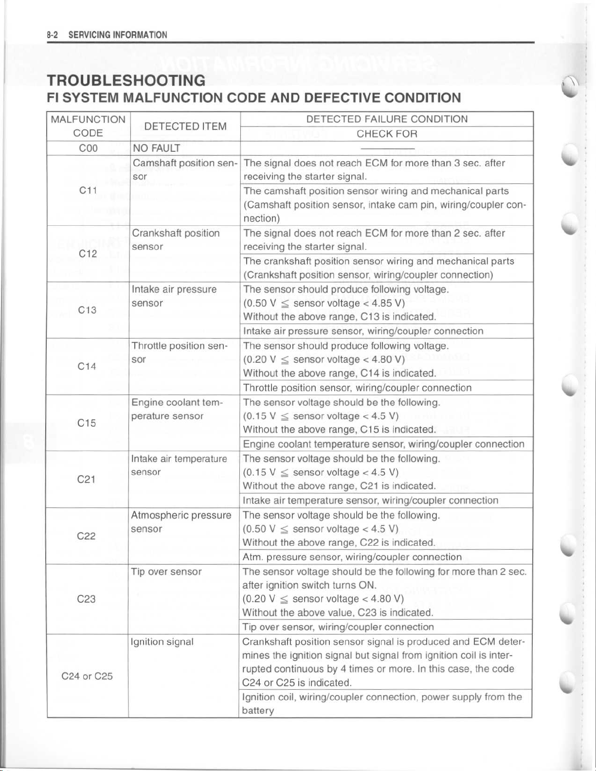
TROUBLESHOOTING
FI SYSTEM MALFUNCTION CODE AND DEFECTIVE CONDITION
MALFUNCTION
CODE
COO
C11
C12
C13
C14
C15
C21
C22
C23
C24 or C25
DETECTED ITEM
NO FAULT
Camshaft position sensor
Crankshaft position
sensor
Intake air pressure
sensor
Throttle position sensor
Engine coolant temperature sensor
Intake air temperature
sensor
Atmospheric pressure
sensor
Tip over sensor
Ignition signal
The signal does not reach ECM for more than 3 sec
receiving the starter signal
The camshaft position sensor wiring and mechanical parts
(Camshaft position sensor, intake cam pin, wiring/coupler connection)
The signal does not reach ECM for more than 2 sec
receiving the starter signal
The crankshaft position sensor wiring and mechanical parts
(Crankshaft position sensor, wiring/coupler connection)
The sensor should produce following voltage
(0
Without the above range, C13 is indicated
Intake air pressure sensor, wiring/coupler connection
The sensor should produce following voltage
(0
Without the above range, C14 is indicated
Throttle position sensor, wiring/coupler connection
The sensor voltage should be the following
(0
Without the above range, C15 is indicated
Engine coolant temperature sensor, wiring/coupler connection
The sensor voltage should be the following
(0
Without the above range, C21 is indicated
Intake air temperature sensor, wiring/coupler connection
The sensor voltage should be the following
(0
Without the above range, C22 is indicated
Atm
The sensor voltage should be the following for more than 2 sec
after ignition switch turns ON
(0
Without the above value, C23 is indicated
Tip over sensor, wiring/coupler connection
Crankshaft position sensor signal is produced and ECM deter-
mines the ignition signal but signal from ignition coil is interrupted continuous by 4 times or more
C24 or C25 is indicated
Ignition coil, wiring/coupler connection, power supply from the
battery
DETECTED FAILURE CONDITION
CHECK FOR
. after
.
. after
.
.
.50 V < sensor voltage < 4
.20 V < sensor voltage < 4
.15 V <_ sensor voltage < 4
.15 V < sensor voltage < 4
.50 V < sensor voltage < 4
. pressure sensor, wiring/coupler connection
.20 V < sensor voltage < 4
.85 V)
.
.
.80 V)
.
.
.5 V)
.
.
.5 V)
.
.
.5 V)
.
.
.80 V)
.
. In this case, the code
.
.
Page 3

SERVICING INFORMATION 8
.3
C28
C29
C31
C32 or C33
C41
C42
C44
C49
Secondary throttle
valve actuator
cated
STVA lead wire/coupler, STVA
Secondary throttle
valve position sensor
The sensor should produce following voltage
(0
Without the above range, C29 is indicated
Secondary throttle position sensor, wiring/coupler connection
Gear position signal
Gear position signal voltage should be higher than the following
for more than 2 seconds
(Gear position switch voltage >_ 0
Without the above value, C31 is indicated
Gear position sensor, wiring/coupler connection, gearshift cam,
etc
Fuel injector
Crankshaft position sensor signal is produced and ECM determines the injection signal but fuel injection signal is interrupted
continuous by 4 times or more
C33 is indicated
Injector, wiring/coupler connection, power supply to the injector
Fuel pump relay
No voltage is applied to fuel pump although fuel pump relay is
turned ON, or voltage is applied to fuel pump although fuel
pump relay is turned OFF
Fuel pump relay, connecting lead, power source to fuel pump
relay
Ignition switch
Ignition switch signal is not input in the ECM
Ignition switch, lead wire/coupler
Heated oxygen sensor
(HO2S) [For E-02, 19]
During 02 feedback control, 02 sensor voltage is higher or
lower than the specification
No signal is detected during engine operation or no electrical
power is supplied from the battery
HO2S lead wire/coupler connection
Battery voltage supply to the HO2S
PAIR control solenoid
valve (PAIR valve)
When no operating voltage is supplied from the ECM, C49 is
indicated
PAIR
No operating voltage is supplied from the ECM, C28 is indi-
. STVA can not operate
.
.
.10 V < sensor voltage < 4
.90 V)
.
.
.6 V)
.
.
. In this case, the code C32 or
.
.
.
.
.
. PAIR valve can not operate
valve
lead wire/coupler
.
Page 4
8-4SERVICING INFORMATION
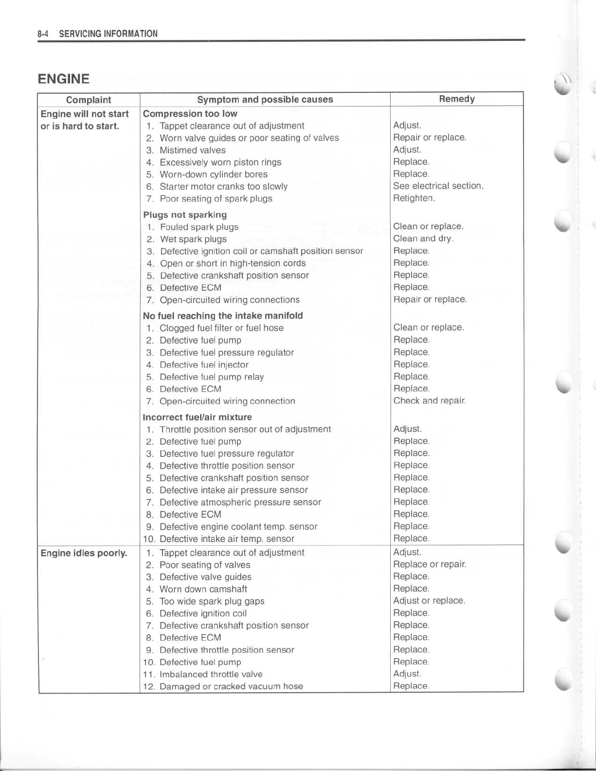
ENGINE
Complaint
Engine will not start
or is hard to start
Engine idles poorly.1
.
Symptom and possible causes
Compression too low
1
. Tappet clearance out of adjustment
2
. Worn valve guides or poor seating of valves
3
. Mistimed valves
4
. Excessively worn piston rings
5
. Worn-down cylinder bores
6
. Starter motor cranks too slowly
7
. Poor seating of spark plugs
Plugs not sparking
1
. Fouled spark plugs
2
. Wet spark plugs
. Defective ignition coil or camshaft position sensor
3
4
. Open or short in high-tension cords
. Defective crankshaft position sensor
5
6
. Defective ECM
7
. Open-circuited wiring connections
No fuel reaching the intake manifold
1
. Clogged fuel filter or fuel hose
2
. Defective fuel pump
. Defective fuel pressure regulator
3
4
. Defective fuel injector
. Defective fuel pump relay
5
6
. Defective ECM
7
. Open-circuited wiring connection
Incorrect fuel/air mixture
1
. Throttle position sensor out of adjustment
2
. Defective fuel pump
3
. Defective fuel pressure regulator
4 . Defective throttle position sensor
5
. Defective crankshaft position sensor
6
. Defective intake air pressure sensor
7
. Defective atmospheric pressure sensor
8
. Defective ECM
. Defective engine coolant temp
9
10
. Defective intake air temp
. Tappet clearance out of adjustment
2
. Poor seating of valves
3
. Defective valve guides
4
. Worn down camshaft
5
. Too wide spark plug gaps
. Defective ignition coil
6
7
. Defective crankshaft position sensor
. Defective ECM
8
9 . Defective throttle position sensor
10
. Defective fuel pump
11
. Imbalanced throttle valve
12
. Damaged or cracked vacuum hose
. sensor
. sensor
Adjust
Repair or replace
Adjust
Replace
Replace
See electrical section
Retighten
Clean or replace
Clean and dry
Replace
Replace
Replace
Replace
Repair or replace
Clean or replace
Replace
Replace
Replace
Replace
Replace
Check and repair
Adjust
Replace
Replace
Replace
Replace
Replace
Replace
Replace
Replace
Replace
Adjust
Replace or repair
Replace
Replace
Adjust or replace
Replace
Replace
Replace
Replace
Replace
Adjust
Replace
Remedy
.
.
.
.
.
.
.
.
.
.
.
.
.
.
.
.
.
.
.
.
.
.
.
.
.
.
.
.
.
.
.
.
.
.
.
.
.
.
.
.
.
.
.
Page 5
SERVICING INFORMATION
8-5
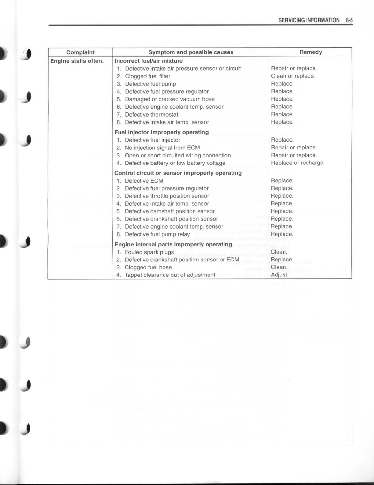
Complaint Symptom and possible causes
Engine stalls often.Incorrect fuel/air mixture
1
. Defective intake air pressure sensor or circuit
2
. Clogged fuel filter
3
. Defective fuel pump
4
. Defective fuel pressure regulator
5
. Damaged or cracked vacuum hose
6
. Defective engine coolant temp
7
. Defective thermostat
8
. Defective intake air temp . sensor
Fuel injector improperly operating
1
. Defective fuel injector
2
. No injection signal from ECM
3
. Open or short circuited wiring connection
4
. Defective battery or low battery voltage
Control circuit or sensor improperly operating
1
. Defective ECM
2
. Defective fuel pressure regulator
3
. Defective throttle position sensor
4
. Defective intake air temp . sensor
5
. Defective camshaft position sensor
6
. Defective crankshaft position sensor
7
. Defective engine coolant temp
8
. Defective fuel pump relay
Engine internal parts improperly operating
1
. Fouled spark plugs
2
. Defective crankshaft position sensor or ECM
3
. Clogged fuel hose
4
. Tappet clearance out of adjustment
. sensor
. sensor
Remedy
Repair or replace
Clean or replace
Replace
Replace
Replace
Replace
Replace
Replace
Replace
Repair or replace
Repair or replace
Replace or recharge
Replace
Replace
Replace
Replace
Replace
Replace
Replace
Replace
Clean
Replace
Clean
Adjust
.
.
.
.
.
.
.
.
.
.
.
.
.
.
.
.
.
.
.
.
.
.
.
.
Page 6
8-6SERVICING INFORMATION
Complaint
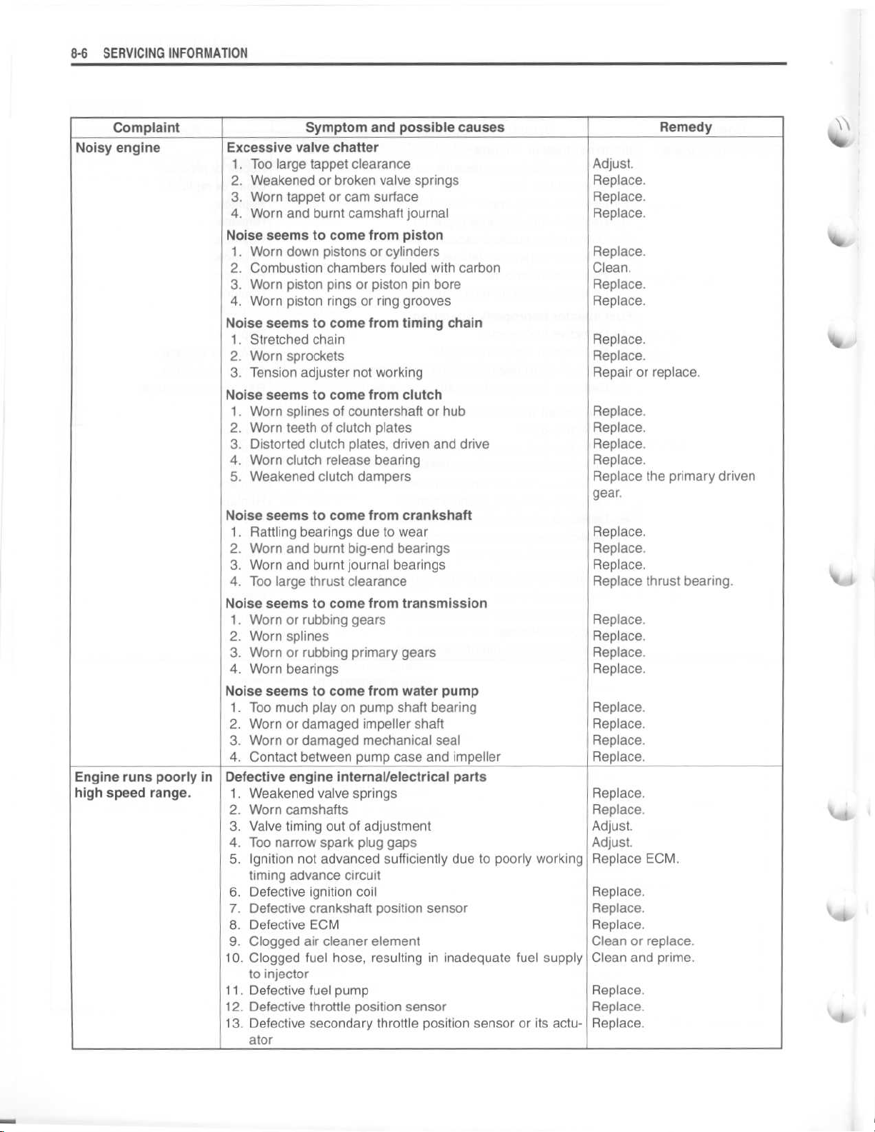
Noisy engine
Noise seems to come from transmission
Noise seems to come from water pump
Engine runs poorly in
high speed range
Defective engine internal/electrical parts
.
10
11
12
13
Symptom and possible causes
Excessive valve chatter
1
. Too large tappet clearance
2
. Weakened or broken valve springs
3
. Worn tappet or cam surface
4
. Worn and burnt camshaft journal
Noise seems to come from piston
1
. Worn down pistons or cylinders
2
. Combustion chambers fouled with carbon
3
. Worn piston pins or piston pin bore
4
. Worn piston rings or ring grooves
Noise seems to come from timing chain
1
. Stretched chain
2
. Worn sprockets
3
. Tension adjuster not working
Noise seems to come from clutch
1
. Worn splines of countershaft or hub
2
. Worn teeth of clutch plates
3 . Distorted clutch plates, driven and drive
4
. Worn clutch release bearing
. Weakened clutch dampers
5
Noise seems to come from crankshaft
1
. Rattling bearings due to wear
2
. Worn and burnt big-end bearings
. Worn and burnt journal bearings
3
4
. Too large thrust clearance
1
. Worn or rubbing gears
2
. Worn splines
3
. Worn or rubbing primary gears
4
. Worn bearings
1
. Too much play on pump shaft bearing
2
. Worn or damaged impeller shaft
3
. Worn or damaged mechanical seal
4
. Contact between pump case and impeller
1
. Weakened valve springs
2
. Worn camshafts
3
. Valve timing out of adjustment
4
. Too narrow spark plug gaps
5
. Ignition not advanced sufficiently due to poorly working
timing advance circuit
6
. Defective ignition coil
7
. Defective crankshaft position sensor
8
. Defective ECM
9
. Clogged air cleaner element
. Clogged fuel hose, resulting in inadequate fuel supply
to injector
. Defective fuel pump
. Defective throttle position sensor
. Defective secondary throttle position sensor or its actu-
ato r
Adjust
.
Replace
Replace
Replace
Replace
Clean
Replace
Replace
Replace
Replace
Repair or replace
Replace
Replace
Replace
Replace
Replace the primary driven
gear
Replace
Replace
Replace
Replace thrust bearing
Replace
Replace
Replace
Replace
Replace
Replace
Replace
Replace
Replace
Replace
Adjust
Adjust
Replace ECM
Replace
Replace
Replace
Clean or replace
Clean and prime
Replace
Replace
Replace
.
.
.
.
.
.
.
.
.
.
.
.
.
.
.
.
.
.
.
.
.
.
.
.
.
.
.
.
.
.
.
.
.
.
.
Remedy
.
.
.
.
.
!I
W
i
I
Page 7
SERVICING INFORMATION 8-7
k I
1 J
1 J
Complaint
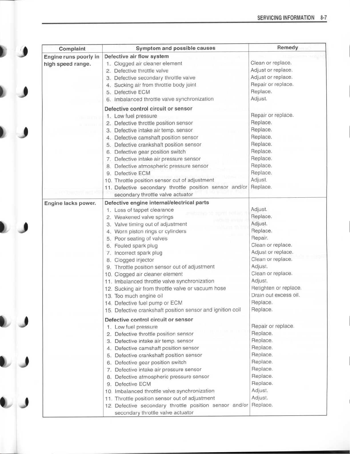
Engine runs poorly in
high speed range
Engine lacks power
Defective air flow system
.
.
Symptom and possible causes
1
. Clogged air cleaner element
. Defective throttle valve
2
3
. Defective secondary throttle valve
. Sucking air from throttle body joint
4
5
. Defective ECM
. Imbalanced throttle valve synchronization
6
Defective control circuit or sensor
. Low fuel pressure
1
2 . Defective throttle position sensor
. Defective intake air temp
3
4
. Defective camshaft position sensor
5
. Defective crankshaft position sensor
. Defective gear position switch
6
7
. Defective intake air pressure sensor
. Defective atmospheric pressure sensor
8
9
. Defective ECM
10
. Throttle position sensor out of adjustment
11
. Defective secondary throttle position sensor and/or
secondary throttle valve actuator
Defective engine internal/electrical parts
. Loss of tappet clearance
1
2
. Weakened valve springs
. Valve timing out of adjustment
3
4
. Worn piston rings or cylinders
. Poor seating of valves
5
6
. Fouled spark plug
7
. Incorrect spark plug
8
. Clogged injector
. Throttle position sensor out of adjustment
9
. Clogged air cleaner element
10
11
. Imbalanced throttle valve synchronization
12
. Sucking air from throttle valve or vacuum hose
. Too much engine oil
13
14
. Defective fuel pump or ECM
. Defective crankshaft position sensor and ignition coil
15
Defective control circuit or sensor
. Low fuel pressure
1
2
. Defective throttle position sensor
. Defective intake air temp
3
4
. Defective camshaft position sensor
. Defective crankshaft position sensor
5
6
. Defective gear position switch
7
. Defective intake air pressure sensor
. Defective atmospheric pressure sensor
8
. Defective ECM
9
. Imbalanced throttle valve synchronization
10
. Throttle position sensor out of adjustment
11
. Defective secondary throttle position sensor and/or
12
secondary throttle valve actuator
. sensor
. sensor
Clean or replace
Adjust or replace
Adjust or replace
Repair or replace
Replace
Adjust
.
Repair or replace
Replace
Replace
Replace
Replace
Replace
Replace
Replace
Replace
Adjust
.
Replace
Adjust
.
Replace
Adjust
.
Replace
Repair
Clean or replace
Adjust or replace
Clean or replace
Adjust
.
Clean or replace
Adjust
.
Retighten or replace
Drain out excess oil
Replace
Replace
Repair or replace
Replace
Replace
Replace
Replace
Replace
Replace
Replace
Replace
Adjust
Adjust
Replace
Remedy
.
.
.
.
.
.
.
.
.
.
.
.
.
.
.
.
.
.
.
.
.
.
.
.
.
.
.
.
.
.
.
.
.
.
.
.
.
.
Page 8
SERVICING INFORMATION
8
-8
Complaint
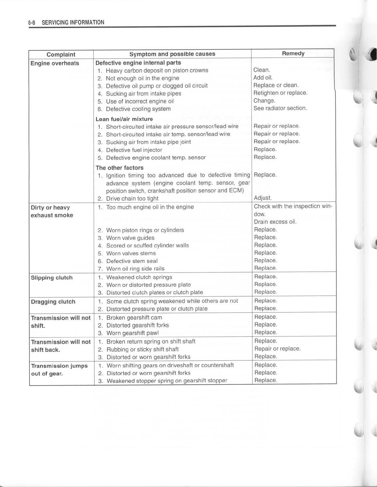
Engine overheats
Dirty or heavy
exhaust smoke
Slipping clutch
Dragging clutch
Transmission will not
shift
.
Transmission will not
shift back
Transmission jumps
out of gear
.
.
Defective engine internal parts
Lean fuel/air mixture
The other factors
Symptom and possible causes
1
. Heavy carbon deposit on piston crowns
. Not enough oil in the engine
2
3
. Defective oil pump or clogged oil circuit
. Sucking air from intake pipes
4
5
. Use of incorrect engine oil
. Defective cooling system
6
. Short-circuited intake air pressure sensor/lead wire
1
2
. Short-circuited intake air temp
. Sucking air from intake pipe joint
3
4
. Defective fuel injector
5
. Defective engine coolant temp
. Ignition timing too advanced due to defective timing
1
advance system (engine coolant temp
position switch, crankshaft position sensor and ECM)
2
. Drive chain too tight
1
. Too much engine oil in the engine
2
. Worn piston rings or cylinders
3
. Worn valve guides
. Scored or scuffed cylinder walls
4
. Worn valves stems
5
6
. Defective stem seal
7
. Worn oil ring side rails
1
. Weakened clutch springs
. Worn or distorted pressure plate
2
3
. Distorted clutch plates or clutch plate
1
. Some clutch spring weakened while others are not
2
. Distorted pressure plate or clutch plate
1
. Broken gearshift cam
. Distorted gearshift forks
2
3
. Worn gearshift pawl
. Broken return spring on shift shaft
1
. Rubbing or sticky shift shaft
2
3
. Distorted or worn gearshift forks
. Worn shifting gears on driveshaft or countershaft
1
2
. Distorted or worn gearshift forks
. Weakened stopper spring on gearshift stopper
3
. sensor/lead wire
. sensor
. sensor, gear
Clean
Add oil
Replace or clean
Retighten or replace
Change
See radiator section
Repair or replace
Repair or replace
Repair or replace
Replace
Replace
Replace
Adjust
Check with the inspection window
.
Drain excess oil
Replace
Replace
Replace
Replace
Replace
Replace
Replace
Replace
Replace
Replace
Replace
Replace
Replace
Replace
Replace
Repair or replace
Replace
Replace
Replace
Replace
Remedy
.
.
.
.
.
.
.
.
.
.
.
.
.
.
.
.
.
.
.
.
.
.
.
.
.
.
.
.
.
.
.
.
.
.
I
Page 9
~
~
~
~
~
1 Y
SERVICING INFORMATION
~
Y
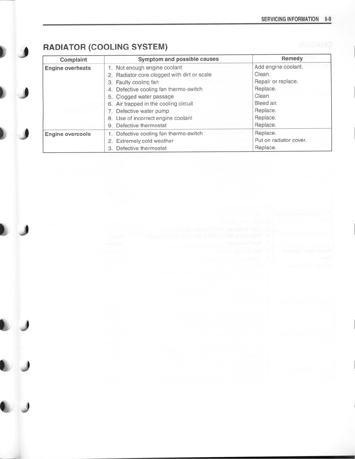
RADIATOR (COOLING SYSTEM)
Complaint Complaint
Engine overheats
Engine
Engine overcools
Engine
Symptom and possible causes
.
1
. Not enough engine coolant
2
. Radiator core clogged with dirt or scale
. Radiator
2
3
. Faulty cooling fan
3
.
.
4
. Defective cooling fan 5
. Clogged water passage
5
.
. Air cooling circuit
6
. Air trapped in the cooling circuit
6
. Defective water pump
7
7
.
8
. Use of incorrect engine coolant
8
.
9
. Defective thermostat
9
.
.
1.Defective cooling
. Extremely cold weather
2
3
. Defective thermostat
cooling
Defective
clogged with dirt or scale
passage
engine coolant
cooling fan thermo-switch
possible causes
coolant
fan thermo-switch
RemedyRemedy
Add engine coolant
Add engine coolant
Clean
.
Clean
.
Repair or replace
Replace
Clean
Clean
Bleed air
Bleed air
Replace
Replace
Replace
Replace
Replace
Put on radiator cover
Replace
.
.
.
.
.
.
.
.
.
.
.
.
.
.
.
8 .9
Page 10
8-10
SERVICING
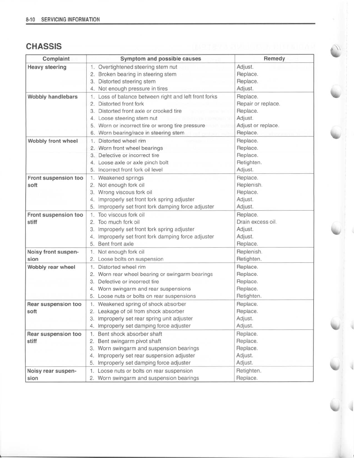
CHASSIS
INFORMATION
Complaint
Heavy steering
Wobbly handlebars
Wobbly front wheel1. Distorted wheel rim
Front suspension too
soft
Front suspension too
stiff
Noisy front suspension
Wobbly rear wheel
Rear suspension too
soft
Rear suspension too
stiff
Noisy rear suspension
1
. Overtightened steering stem nut
. Broken bearing in steering stem
2
3
. Distorted steering stem
4
. Not enough pressure in tires
1
. Loss of balance between right and left front forks
2
. Distorted front fork
3
. Distorted front axle or crooked tire
4
. Loose steering stem nut
. Worn or incorrect tire or wrong tire pressure
5
6
. Worn bearing/race in steering stem
2
. Worn front wheel bearings
3
. Defective or incorrect tire
4
. Loose axle or axle pinch bolt
5
. Incorrect front fork oil level
1
. Weakened springs
2
. Not enough fork oil
3
. Wrong viscous fork oil
4
. Improperly set front fork spring adjuster
. Improperly set front fork damping force adjuster
5
1
. Too viscous fork oil
2
. Too much fork oil
3
. Improperly set front fork spring adjuster
4
. Improperly set front fork damping force adjuster
5
. Bent front axle
1
. Not enough fork oil
2
. Loose bolts on suspension
1
. Distorted wheel rim
2
. Worn rear wheel bearing or swingarm bearings
3
. Defective or incorrect tire
4
. Worn swingarm and rear suspensions
5
. Loose nuts or bolts on rear suspensions
1
. Weakened spring of shock absorber
2
. Leakage of oil from shock absorber
3
. Improperly set rear spring unit adjuster
4
. Improperly set damping force adjuster
1
. Bent shock absorber shaft
2
. Bent swingarm pivot shaft
3
. Worn swingarm and suspension bearings
4
. Improperly set rear suspension adjuster
. Improperly set damping force adjuster
5
1
. Loose nuts or bolts on rear suspension
2
. Worn swingarm and suspension bearings
Symptom and possible causes
Remedy
Adjust
.
Replace
Replace
Adjust
Replace
Repair or replace
Replace
Adjust
Adjust or replace
Replace
Replace
Replace
Replace
Retighten
Adjust
Replace
Replenish
Replace
Adjust
Adjust
Replace
Drain excess oil
Adjust
Adjust
Replace
Replenish
Retighten
Replace
Replace
Replace
Replace
Retighten
Replace
Replace
Adjust
Adjust
Replace
Replace
Replace
Adjust
Adjust
Retighten
Replace
.
.
.
.
.
.
.
.
.
.
.
.
.
.
.
.
.
.
.
.
.
.
.
.
.
.
.
.
.
.
.
.
.
.
.
.
.
.
.
.
.
.
V&
%r
Page 11
~
a
,
a
Si
Si
•
i
J
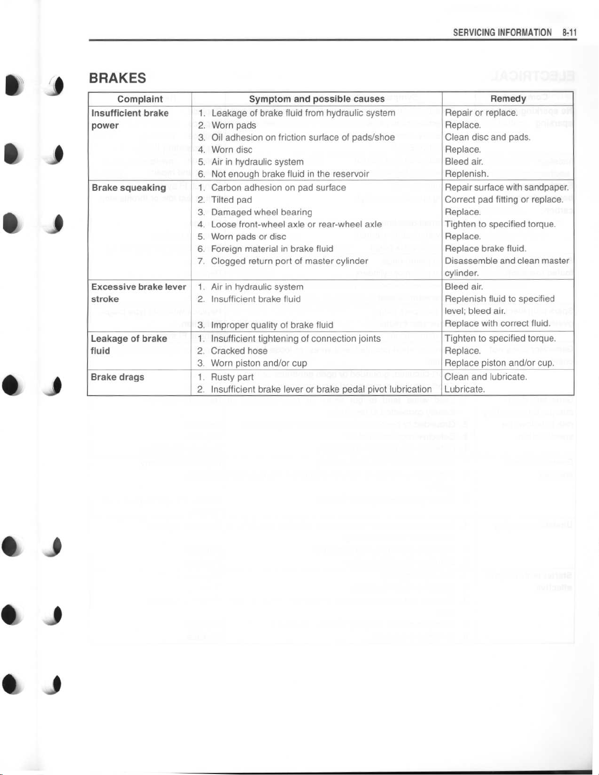
Complaint
Insufficient brake
power
Brake squeaking
Excessive brake lever
stroke
Leakage of brake
fluid
Brake drags
SERVICING INFORMATION
Symptom and possible causes
1
. Leakage of brake fluid from hydraulic system
2
. Worn pads
3
. Oil adhesion on friction surface of pads/shoe
4
. Worn disc
. Air in hydraulic system
5
6
. Not enough brake fluid in the reservoir
1
. Carbon adhesion on pad surface
2
. Tilted pad
3
. Damaged wheel bearing
4
. Loose front-wheel axle or rear-wheel axle
5
. Worn pads or disc
6 . Foreign material in brake fluid
7
. Clogged return port of master cylinder
1
. Air in hydraulic system
2
. Insufficient brake fluid
. Improper quality of brake fluid
3
1
. Insufficient tightening of connection joints
2
. Cracked hose
3
. Worn piston and/or cup
1
. Rusty part
2
. Insufficient brake lever or brake pedal pivot lubrication
Repair or replace
Replace
Clean disc and pads
Replace
Bleed air
Replenish
Repair surface with sandpaper
Correct pad fitting or replace
Replace
Tighten to specified torque
Replace
Replace brake fluid
Disassemble and clean master
cylinder
Bleed air
Replenish fluid to specified
level
Replace with correct fluid
Tighten to specified torque
Replace
Replace piston and/or cup
Clean and lubricate
Lubricate
Remedy
.
.
.
.
.
.
.
.
; bleed air
.
.
8-11
.
.
.
.
.
.
.
.
.
.
.
Si
0 1
Ii
Page 12
8
-12 SERVICING
INFORMATION
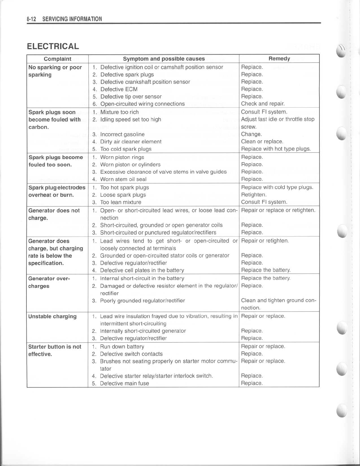
ELECTRICAL
Complaint Symptom and possible causes
1
No sparking or poor
sparking
Spark plugs soon
become fouled with
carbon
Spark plugs become
fouled too soon
Spark plug electrodes
overheat or burn
Generator does not
charge
Generator does
charge, but charging
rate is below the
specification
Generator overcharges
Unstable charging
Starter button is not
effective
.
.
.
.
.
.
. Defective ignition coil or camshaft position sensor
2
. Defective spark plugs
. Defective crankshaft position sensor
3
4
. Defective ECM
. Defective tip over sensor
5
6
. Open-circuited wiring connections
1
. Mixture too rich
2
. Idling speed set too high
. Incorrect gasoline
3
4
. Dirty air cleaner element
5
. Too cold spark plugs
1
. Worn piston rings
2
. Worn piston or cylinders
3
. Excessive clearance of valve stems in valve guides
4
. Worn stem oil seal
1
. Too hot spark plugs
2
. Loose spark plugs
3
. Too lean mixture
1
. Open- or short-circuited lead wires, or loose lead con-
nection
2
. Short-circuited, grounded or open generator coils
. Short-circuited or punctured regulator/rectifiers
3
. Lead wires tend to get short- or open-circuited or
1
loosely connected at terminals
. Grounded or open-circuited stator coils or generator
2
3
. Defective regulator/rectifier
4
. Defective cell plates in the battery
1
. Internal short-circuit in the battery
2
. Damaged or defective resistor element in the regulator/
rectifier
3
. Poorly grounded regulator/rectifier
. Lead wire insulation frayed due to vibration, resulting in
1
intermittent short-circuiting
2 . Internally short-circuited generator
3
. Defective regulator/rectifier
1
. Run down battery
2
. Defective switch contacts
. Brushes not seating properly on starter motor commu-
3
tator
4
. Defective starter relay/starter interlock switch
5
. Defective main fuse
\\
Remedy
Replace
Replace
Replace
Replace
Replace
Check and repair
Consult FI system
Adjust fast idle or throttle stop
screw
Change
Clean or replace
Replace with hot type plugs
Replace
Replace
Replace
Replace
Replace with cold type plugs
Retighten
Consult FI system
Repair or replace or retighten
Replace
Replace
Repair or retighten
Replace
Replace
Replace the battery
Replace the battery
Replace
Clean and tighten ground connection
Repair or replace
Replace
Replace
Repair or replace
Replace
Repair or replace
.
Replace
Replace
.
.
.
.
.
.
.
.
.
.
.
.
.
.
.
.
.
.
.
.
.
.
.
.
.
.
.
.
.
.
.
.
.
.
.
.
Page 13

I P
P
BATTERY
Complaint
1
"Sulfation", acidic
white powdery substance or spots on
surfaces of cell plates
Battery runs down
quickly
Battery "sulfation"1. Incorrect charging rate
.
. Cracked battery case
. Battery has been left in a run-down condition for a long
2
time
1
. Trouble in charging system
2
. Cell plates have lost much of their active material as a
result of overcharging
. Internal short-circuit in the battery
3
4
. Too low battery voltage
. Too old battery
5
(When not in use battery should be checked at least
once a month to avoid sulfation
. The battery was left unused in a cold climate for too
2
long
Symptom and possible causes
.
.
.
.)
SERVICING INFORMATION 8-12
Remedy
Replace the battery
Replace the battery
Check the generator, regulator/
rectifier and circuit connections
and make necessary adjustments to obtain specified
charging operation
Replace the battery, and correct the charging system
Replace the battery
Recharge the battery fully
Replace the battery
Replace the battery
Replace the battery if badly
sulfated
.
.
.
.
.
.
.
.
.
1 l
J
1 1
Page 14
8-14
SERVICING INFORMATION
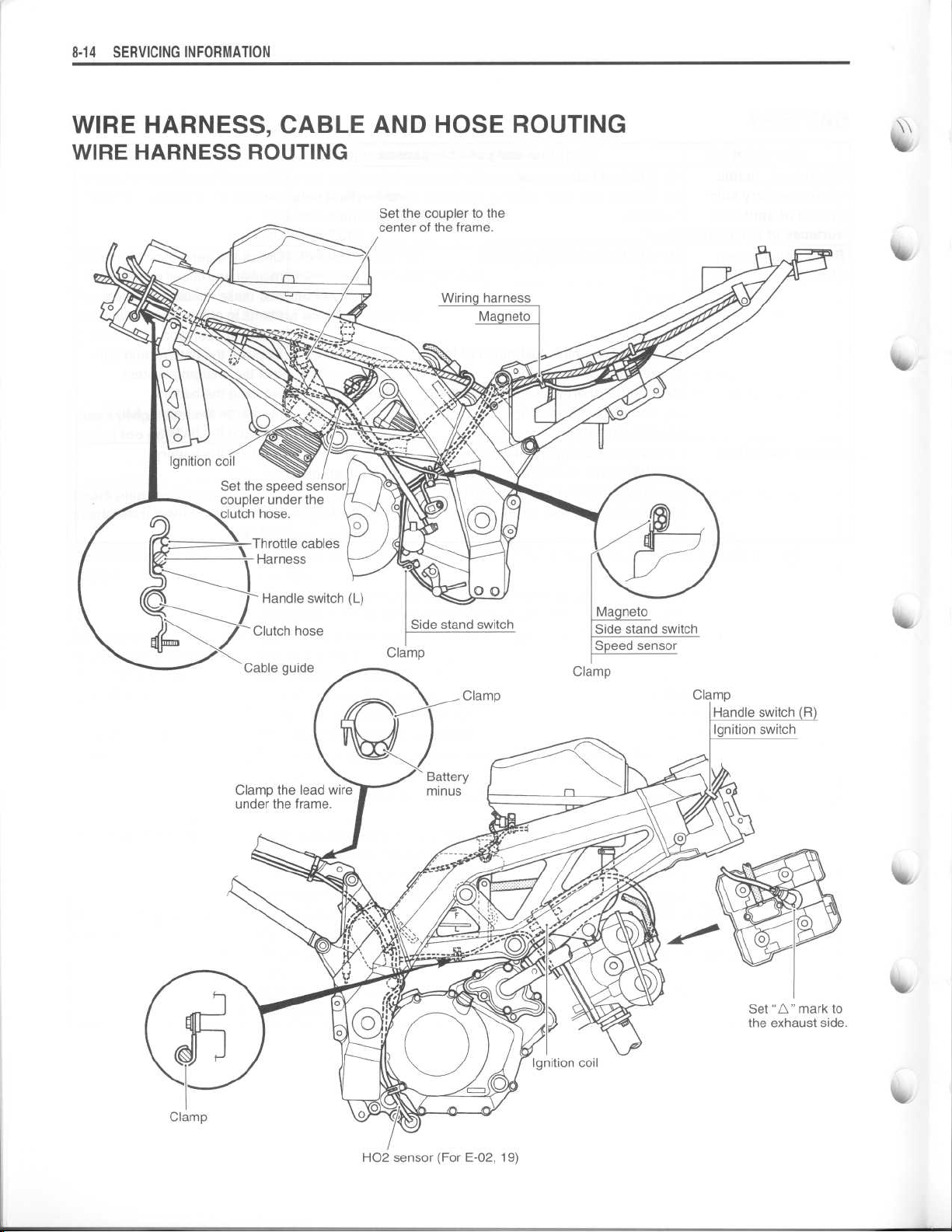
WIRE HARNESS, CABLE AND HOSE ROUTING
WIRE HARNESS ROUTING
Set the coupler to the
Ignition coil
Set the speed sensor
coupler under the
clutch hose
center of the frame
.
.
Handle switch (L)
/ Clutch hose
Cable guide
Clamp
Clamp
Set "A" mark to
the exhaust side
.
Clamp
H02 sensor (For E-02, 19)
Page 15

~
Horn
Set the connector and harness
between the frame and
the reservoir tank
.
SERVICING INFORMATION
Clamp the harness without contacting
to the bracket
.
Clamp
Harness
Rear
turn signal
Licence
lamp
8-15
light
(L)
Taping clamp
Taping clamp
Set
"s"
the exhaust side
mark to
.
Set the coupler inside of
the triangle area between
Set the high tension cord
backward as much as possible
without contacting to the fuel tank
Head lamp
the frame and fender
.
.
Page 16

SERVICING INFORMATION
8-16
ENGINE ELECTRICAL PARTS SET-UP
Apply bond to the groove
of the grommet
.
0
#2 Cylinder
I
Apply bond to the groove
of the grommet
.
10 N
.m
.0 kgf-m, 7
(1
Forward
.3 lb-ft)
Page 17

SERVICING INFORMATION8.17
1
1 1
I )
1
•
REGULATOR/RECTIFIRE INSTALLATION
0
I
l
't
Page 18

8-18
SERVICING INFORMATION
THROTTLE CABLE ROUTING
Throttle cable (pull)
Throttle cable (return)
Harness
Handle switch (L)
Throttle cable guide (pull)
Throttle cable guide (return)
Page 19

~
~
THROTTLE BODY INSTALLATION/HOSE ROUTING
I
1 J
SERVICING INFORMATION 8-19
1 J
1
Water temperature sensor
18 N
•m
(1
.8 kgf-m, 13 lb-ft)
\\
Forward
15-25°
VIEW OF TOP
(Throttle body clamp position)
25°
Air cleaner side
(A
1 l
down side
:
OA
: The ends of the clamp face
©
.
The clamp bolt head faces
. . .
. . .
Air temperature sensor
18 N
•m
(1
.8 kgf-m, 13 lb-ft)
Page 20

8-20
SERVICING INFORMATION
CRANKCASE BREATHER HOSE ROUTING
The clamp bolt head faces
OA
:
©
: The ends of the clamp face
© right side
Breather hose
. .
.
. . .
.
Page 21

S
.Y
Y
y
CLUTCH HOSE ROUTING
VIEW A
After the clutch cable hose union touching to the stopper,
tighten the union bolt
SERVICING INFORMATION 8-21
.
Si
1 l
Clamp the clutch hose firmly
.
Pass through the clutch hose
outside of the guide
SECT C
Clamp the clutch hose firmly
.
l
A-
.
d
l
0
After the clutch hose union
touching to the stopper,
)
tighten the union bolt
.
Page 22

~
8-22
SERVICING INFORMATION
COOLING SYSTEM HOSE ROUTING
Pass through the reservoir hose
right side of the breather hose and
high tension cord
.
(O
bottom side
.
© right side
© front side
Pass through
the reservoir
hose notch of
heat shield
.
.
:
The ends of the clamp face..
OA
©
: The clamp bolt head faces
.
Press fitting position of bearing
surface of clutch cover
.
© up side
. . .
.
.
4
-
u
'~
Tighten the clamp bolt to the
0
specified torque
2 N -m (0
.
.2 kg-m, 1
.5 lb-ft)
side
OA u
side
.
p
.
Page 23

~
W
O
w
w w
After the brake hose union
touching to the stopper,
tighten the union bolt
.
After the brake hose unions
touching to the stopper,
tighten the union bolt
.
After positioning the clamp
with the stopper,
tighten the clamp bolt
Insert the clamp /
to the hole of the
front fender fully
After the brake hose union touching
to the stopper, tighten the union bolt
.
.
.
Page 24

Be careful not to contact the seat rail and
reservoir tank, when installing
The white paint faces outside
.
.
Face the clamp ends backward
After the brake hose union touching
to the stopper, tighten the union bolt
.
.
After the brake hose union touching
to the stopper, tighten the union bolt
.
Page 25

SERVICING INFORMATION
8-25
k
j
s
FUEL TANK DRAIN HOSE ROUTING
Si
41 1
1
1
6
Page 26

8-
2 6
SERVICING INFORMATION
FUEL TANK INSTALLATION
Page 27

~
PAIR (AIR SUPPLY) SYSTEM HOSE ROUTING
k
~7
I
k j
1 1
Matching mark
(White)
SERVICING INFORMATION
8-27
0 p
1 1
Si
-
~m
o
i
Matching mark
(Yellow)
ME
.
10 N
.m 1
.0 kgf-m, 7
A
.0 lb-ft)
r„(©7
w
1
PAIR read valve
Page 28

SERVICING INFORMATION
8-28
SEAT LOCK CABLE ROUTING
Seat lock cable
Page 29

1 1
1 1
SIDE-STAND SET-UP
0
40 N
(4
.0 kgf-m, 29
.m
SERVICING INFORMATION
.0 Ib-ft)
8-29
j
1 1
comi(comal
0
100 N
.m
(10 .0 kgf-m, 72
BRAKE PEDAVFOOTREST SET-UP
.5 Ib-ft)
C
I
[950N
.m
.0 kgf-m, 36
(5
.0 Ib-ft)
I )
ii )
0
1
a
Page 30

8-30
SERVICING INFORMATION
SPECIAL TOOLS
09900-00410
Hexagon wrench set
09900-06107
Snap ring pliers
09900-06108
Snap ring pliers
09900-09004
Impact driver set
I
kAo
09900-18740
Hexagon wrench
(24 mm)
r
1
1111110
!s
09900-20101 or
09900-20102 Micrometer Micrometer Micrometer
Vernier calipers
I
09900-20607 09900-20803
Dial gauge
(1/100 mm, 10 mm)
q
U®
i~
Orr,
-
9
9~
o
2i
09900-q
09900-22302
Plastigauge
3.r2
0
1
09900-20202 09900-20204 09900-20205
(25-50 mm)
®r
r,
09900-20701
Magnetic stand
09900-22403
Small bore gauge
(18 -
35 mm)
(75-100 mm)
~
09900-20806 09900-20805 09900-21304
Thickness gauge
09900-25008 09900-25009 09913-10750
Multi circuit tester
set
(0-25 mm)
Tire depth gaugeV-block (100 mm)
Needle pointed
probe set
~
\
~'
taq
09900-20602
Dial gauge
(1/1 000 mm, 1 mm)
l
ot
.
1Cir
Compression gauge
adapter
09913-13121
Carburetor balancer
set
09913-50121
Oil seal remover
09913-60210
Journal bearing
remover/installer set
09913-60230 09913-60240
Journal bearing Journal bearing
remover/installer
ro
holder
Page 31

I P
k P
k j
4Ir
09913-70210
Bearing installer set
~
09915-40610
Oil
\
filter wrench
09915-64512
Compression gauge
SERVICING INFORMATION8-3
09915-72410
Oil pressure gauge
attachment
09915-74511
Oil pressure
1
gauge
I
e
09915-74521
Oil pressure gauge
hose
09916-14910
Valve spring com-
pressor attachment
09916-34550
Valve guide reamer
(5
.5 mm)
09915-74532
Oil pressure gauge
adaptor
09916-21111
Valve
seat cutter set
09916-34580
Valve guide reamer
(10
.8 mm)
09915-77331
Meter (for high pres-
sure)
09916-24480
Solid pilot
(N-140-5
09916-44910
Valve guide
remover/installer
.5)
09916-10911
Valve lapper set
Valve seat cutter
head
See page 3-42
09916-53340
Attachment
09916-14510
Valve spring com-
pressor
09916-34542
.
Reamer handle
09916-84511
Tweezers
09917-47010
Vacuum pump
gauge
;P
0
09920-13120
Crankcase separating tool
09920-53740
Clutch sleeve hub
holder
09921-20240
Bearing remover set
i
09923-73210
Bearing remover
Page 32

8-32
SERVICING INFORMATION
i
09923-74511
Bearing puller
Final drive gear
bearing installer/
remover
001
~09924-74570
09924-84510
Bearing installer set
09924-84521
Bearing installer set
~g4
09925-18011
Steering bearing
installer
09930-10121
Spark plug wrench
set
09930-30450
Rotor remover bolt
09940-14911
Steering stem nut
wrench
09930-11920
Torx bit JT40H
09930-44541
Rotor holder
®
09940-14940
Swingarm pivot
thrust adjuster
socket wrench
09930-11940
Bit holder
09930-73110
Startertorque
holder
09940-14960
Steering nut wrench
socket
limiter
± i
09930-11950
09930-11960
Torx wrench
09930-73120
Starter
socket
torque limiter
O
09940-14990
Engine mounting
thrust adjuster
socket wrench
09930-30102
Sliding shaft
09930-82720
Mode selection
switch
F
09940-30250
Front fork assem-
bling tool
All
-
09940-40211
Fuel pressure gauge
adapter
IPlI
_
09940-40220
Fuel pressure gauge
hose attachment
09940-52841
Front fork inner rod
holder
~,
"
P
AR
09940-52861
Front fork oil seal
installer
09940-92720
Spring scale
Page 33

SERVICING INFORMATION 8-
3 3
1
•
1 f
1 0
0 9941-34513
Steering race
installer
NOTE
: When ordering a special tool, please confirm whether it is available or not
09943-74111
Fork oil level gauge
.
4 j
0 )
k
)
Page 34

~
~
~
~
~
~
~
~
~
~
~
8-34 SERVICING INFORMATION
TIGHTENING TORQUE
ENGINE
ITEM N-m
Cylinder head cover bolt
Spark plug
Camshaft journal holder bolt
Cam chain tension adjuster bolt
Cam chain tension adjuster mounting bolt
Cam drive idle gear/sprocket shaft
Cam chain tensioner mounting bolt
Cylinder head nut
Cylinder head bolt
PAIR read valve cover bolt
Cylinder nut
Water drain bolt
Clutch sleeve hub nut
Clutch spring set bolt
Clutch spring support bolt
Cam drive idle gear/sprocket nut
Primary drive gear nut
Generator cover plug
Valve timing inspection plug
Generator rotor bolt
Starter clutch bolt
Generator stator set bolt
Generator stator clamp bolt
Crankshaft position sensor set bolt
Gear position sensor mounting bolt
Gearshift cam stopper bolt
Gearshift cam stopper plate bolt
Gearshift arm stopper bolt
Oil pressure switch
Crankcase bolt
Generator cover bolt
Clutch cover bolt
Gearshift cover bolt
Water pump case bolt
Oil gallery plug
[M
[M
[M
[M
[M
[M
[M
[M
[M
[M
[M
[M
[M
[M
[F]
[R]
: 8]
: 6]
: 10]
: 6]
: 6]
: 6]
: 6]
: 8]
: 6]
: 6]
: 6]
: 6]
: 16]
: 8]
14
11
10
23
7 0
10
40
10
25
10
47
10
10
10
5
.5
95
10
23
70
115
15
23
140
25
12
6
.5
6
.5
6
.5
10
10
23
14
11
26
11
11
11
10
35
18
kgf-m
1
.4
1 .1
1
.0
2
.3
.7
1
.0
4
.0
1
.0
2
.5
1
.0
4
.7
1
.0
1
.0
1
.0
0
.55
9
.5
1
.0
2
.3
7
.0
11
.5
1
.5
2
.3
14
.0
2
.5
1
.2
0
.65
0
.65
0
.65
1
.0
1
.0
2
.3
1
.4
1
.1
2
.6
1
.1
1
.1
1
.1
1
.0
3
.5
1
.8
lb-ft
10
8
.0
7
.0
16
5
.0
7
.0
29
7
.0
18
7
.0
34
7
.0
7
.0
7
.0
4
.0
68
7
.0
16
50
83
11 .0
16
101
18
8
.5
4
.7
4
.7
4
.7
7
.0
7
.0
16
10
8
.0
19
8
.0
8
.0
8
.0
7
.3
25
.5
13
.0
.0
.5
.0
.0
.0
.5
.5
.5
.0
.5
.0
.0
.5
.0
.0
Page 35

~
ITEM N
Oil drain plug
Piston cooling oil nozzle screw
Oil pump mounting bolt
Conrod bearing cap bolt
Muffler mounting bolt and exhaust pipe bolt
Muffler mounting nut
Oil cooler mounting bolt
Oil cooler hose union bolt
Engine sprocket nut
Engine mounting pinch bolt
Engine mounting bolt/nut
Engine mounting thrust adjuster
Engine mounting thrust adjuster lock nut
Cooling fan thermo-switch
(Initial)
(Final)
[M
: 12]
[M
: 10]
•m
23
8 0
10
35
After tightening to
a turn (90°)
.
23
25
10
23
115
23
93
55
12
45
17
kgf-m
the above torque,
SERVICING INFORMATION 8-
Ib-ft
2
1
3
2
2
1
2
11
2
9
5
1
4
1
.3
.8
.0
.5
.3
.5
.0
.3
.5
.3
.3
.5
.2
.5
.7
16
.5
6
.0
7
.0
25
.5
tighten 1/4 of
16
.5
18
7
.3
16
83
16
67
40
8
.5
32
12
.0
.5
.0
.5
.6
.0
.5
.5
3
5
FI SYSTEM PARTS
ITEM
ECTS
TATS
CMPS mounting bolt
H02 sensor (For E-02, 19)
Fuel delivery pipe mounting screw
Fuel pump mounting bolt
Throttle body connecting bolt
Actuator motor cover nut
TPS mounting screw
STPS mounting screw
N•m
18
18
10
47
.5
5 0
10
5 0
2 0
3
.5
2 0
kgf-m
1
.8
1
.8
1
.0
4
.75
.5
1
.0
.5
.2
0
.35
.2
I b-ft
13
.0
13
.0
7
.3
34
.3
3
.7
7
.3
3
.7
1
.5
2
.5
1
.5
Page 36

~
8-36
SERVICING INFORMATION
CHASSIS
ITEM
Steering stem head nut
Steering stem lock nut
Front fork upper clamp bolt
Front fork lower clamp bolt
Front fork cap bolt
Front fork inner rod lock nut
Front fork damper rod bolt
Front axle
Front axle pinch bolt
Handlebar clamp bolt
Front brake master cylinder mounting bolt
Front brake caliper mounting bolt
Front brake caliper housing bolt
Front brake pad mounting pin
Brake hose union bolt
Clutch master cylinder mounting bolt
Clutch hose union bolt
Air bleeder valve (Clutch)
Air bleeder valve (Front)
Air bleeder valve (Rear)
Front brake disc bolt
Rear brake caliper mounting bolt
Rear brake caliper sliding pin
Rear brake master cylinder mounting bolt
Rear brake master cylinder rod lock nut
Rear brake pad mounting pin
Rear brake pad mounting pin plug
Front footrest bracket mounting bolt
Front footrest bolt
Swingarm pivot shaft
Swingarm pivot nut
Swingarm pivot shaft lock nut
Rear shock absorber mounting nut (Upper and lower)
Cushion lever mounting nut (Front)
Cushion rod mounting nut (Upper and lower)
Rear brake disc bolt
Rear axle nut
Rear sprocket nut
Seat rail bolt
Steering damper bolt
Steering damper nut
Steering stem nut
(For E-03, 28, 33)
(For the others)
N -m
90
80
23
23
23
15
23
100
23
23
10
26
23
16
23
10
23
5
.4
7
.5
6 0
23
23
27
10
18
18
2
.5
23
39
15
100
90
50
78
78
35
100
120
60
55
23
23
45
kgf-m
9
.0
8
.0
2
.3
2
.3
2
.3
1
.5 11 .5
2
.3
10
.0
2
.3
2
.3
1
.0
2
.6
2
.3
1
.6 11 .5
2
.3
1
.0
2
.3
0
.54
0
.75
.6
2
.3
2
.3
2
.7
1
.0
1
.8
1
.8
0
.25
2
.3
3
.9
1
.5
10
.0
9
.0
5
.0
7
.8
7
.8
3
.5
10
.0
12
.0
6
.0
5
.5
2
.3
2
.3
4
.5
I
b-ft
65
58
16
16
16
16
72
16
16
7
19
16
16
7
16
4
5
4
16
16
20
7
13
13
1
16
28
11
70
65
36
56
56
25
72
87
43
40
16
16
32
.0
.0
.5
.5
.5
.5
.5
.5
.5
.0
.0
.5
.5
.0
.5
.0
.5
.4
.5
.5
.5
.0
.0
.0
.8
.5
.0
.0
.0
.0
.0
.5
.5
.5
.5
.0
.5
.0
.5
.5
.5
Page 37

TIGHTENING TORQUE CHART
For other bolts and nuts listed previously, refer to this chart
:
SERVICING INFORMATION 8-
7
3
1 f
1 0
Bolt Diameter
®
(mm)
4
5 3 0
6 5
8 13
10
12
14
16
18
OA
Conventional bolt
Conventional or "4" marked bolt
N
•m
1
.5
.5
29
45
65
105
160
kgf-m
0
.15
.3
0
.55
1
.3 9
2
.9
4
.5
6
.5
10
.5
16
.0
lb-ft
1
.0
2
.0
4
.0
.5
21
.0
32
.5
47
.0
76
.0
115
.5
ORION
"4" marked bolt
"7" marked bolt
N
•m
2
.3
4
.5
10
23
50 5
85
135
210
240
kgf-m
0
.23
0
.45
1
.0
2
.3
.0
8
.5
13
.5
21
.0
24
.0
"7" marked bolt
lb-ft
1
.5
3
.0
7
.0
16
.5
36
.0
61
.5
97
.5
152
.0
173
.5
1 0
0
1 0
I
P
Page 38

8-38 SERVICING INFORMATION
SERVICE DATA
VALVE + GUIDE
ITEM
Valve diam
Tappet clearance (when cold)
Valve guide to valve stem clearance
Valve guide I .D
Valve stem O.D.
Valve stem deflection
Valve stem runout
Valve head thickness
Valve seat width
Valve head radial runout
Valve spring free length
Valve spring tension
.
.
EX
EX
IN
EX
IN
. & EX
IN
EX
IN
. & EX
IN
. & EX
IN
. & EX
IN
. & EX
IN
. & EX
IN
. & EX
IN
. & EX
IN
IN
116
Unit
: mm (in)
STANDARD
36
(1
.42)
.
.
.
.
.
.
.
.
.
.
.
.
.
(20.1- 23
(0
(0
(0
(0
(0
at length 35
33
(1
.30)
0
.10-0
(0
.004 -0.008)
0
.20-0
(0
.008 -0.012)
0
.010 -0.046
.0004-0
0
.030 - 0
.0012-0
5
.500 -5.512
.2165 -0.2170)
5
.475-5
.2156-0
5
.455 - 5
.2148 -0.2154)
0
(0
.035
197-227 N
.1 kgf, 44
.20
.30
.0018)
.066
.0026)
.490
.2161)
.470
.9-1
.1
- 0
.043)
.3 -51.0 Ibs)
.6 mm (1
.40 in)
LIMIT
0
.35
(0
.014)
0
.05
(0
.002)
0
.5
(0 .02)
0
.03
(0
.001)
41
.2
(1
.62)
CAMSHAFT + CYLINDER HEAD
ITEM
Cam height
Camshaft journal oil clearance
Camshaft journal holder I
Camshaft journal O.D.
Camshaft runout
.D
.
IN
EX
IN
. & EX
IN
. & EX
IN
. & EX
IN
. & EX
.
.
.
.
.
STANDARD
37
.78 -
(1
.487-1
36
.38 - 36 .42
(1
.432 -1.434)
0
.019 - 0
(0
.0007 - 0
22
.012-22
(0
.8666 -0.8671)
21
.972
(0
.8650 -0.8659)
37
.053
.0021)
- 21
.82
.489)
.025
.993
Unit
: mm (in)
LIMIT
37
.48
(1
.476)
36
.08
(1
.420)
0
.150
(0
.0059)
0
.10
(0
.004)
Page 39

~
SERVICING INFORMATION 8-39
ITEM
Cam drive idle gear/sprocket
thrust clearance
Cylinder head distortion
ITEM
Compression pressure
(Automatic de-comp
Compression pressure difference
Piston to cylinder clearance
Cylinder bore
Piston diam
Cylinder distortion
Piston ring free end gap
Piston ring end gap
Piston ring to groove clearance
Piston ring groove width
Piston ring thickness
Piston pin bore I.D.
Piston pin O.D.
.
. actuated)
STANDARD
0
(0
STANDARD
1k000gf-
(10
- 14 gf/cm2,
0
(0
.0006 - 0
98
(3
.8583 -3.8589)
97
(3
.8575 - 3 .8581)
Measure at 10 mm (0
1st
2nd
1 st
2nd
1 st
2nd
1 st
2nd
Oil
1 st
2nd
22
.002-22
(0
.8662-0
21
.993-22
(0
.8658-0
.15-0
.006 -
.015
.000-98
.980-97
.29
.011)
0
_
1 400 kPa
142-199 psi)
-
- 0
.025
.0010)
.015
.995
.4 in) from the skirt end
Approx
Approx
(0
(0
(0
(0
. 8
.8 (0
.35)
. 10 .1 (0
0
.15-0
(0
.006 -0.014)
0
.30-0
(0
.012
0
.93-0
.0366 -0.0374)
1
.55-1
.0610-0
1
.01 -1
.0398-0
2
.51 -2
.0988 - 0
.86-0
0
.034
(0
.38-1
1
(0
.054-0
0
.97-0
(0
.038 -0.039)
- 0
- 0
.008
.8665)
.000
.8661)
.35
.45
.018)
.95
.57
.0618)
.03
.0406)
.53
.0996)
.91
.036)
.40
.055)
.99
.40)
LIMIT
0
.05
(0
.002)
Unit
: mm (in)
LIMIT
800 kPa
(8 kgf/cm2,
114 psi)
200 kPa
(2 kgf/cm2,
28 psi)
0
.12
(0
.0047)
Nicks or
Scratches
97
.880
(3
.
.8535)
0
.05
(0
.002)
7
.0
(0
.28)
8
.1
(0
.32)
0
.7
(0 .03)
0
.7
(0
.03)
0
.18
(0
.0071)
0
.15
(0
.0059)
-
_
22
.030
(0
.8673)
21 .980
(0
.8654)
Page 40

8-40
SERVICING INFORMATION
CONROD + CRANKSHAFT
ITEM
Conrod small end I.D.
Conrod big end side clearance
Con rod big end width
Crank pin width
Conrod big end oil clearance
Crank pin O.D.
Crankshaft journal oil clearance
Crankshaft journal O.D.
Crankshaft runout
OIL PUMP
ITEM
Oil pressure (at 60 °C, 140 °F)
STANDARD
22
.010-22
(0
.8665 - 0
0
.17-0
(0
.007 -0.013)
21
.95-22
(0
.864-0
44
.17-44
(1
.739 - 1
0
.040
(0
.0016 - 0
44
.976-45
(1
.7707
0
.002-0
(0
.0008 - 0
47
.985-48
(1
.8892 - 1
STANDARD LIMIT
Above 350 kPa (3
Below 650 kPa (6
at 3 000 r/min
.018
.8668)
.32
.00
.866)
.22
.741)
- 0
.064
.0025)
.000
- 1
.7717)
.029
.0011)
.000
.8898)
.5 kgf/cm2, 50 psi)
.5 kgf/cm2,
92 psi)
Unit
LIMIT
22
(0
.8677)
0
(0
0.080
(0
.0031)
0.080
(0
.0031)
0
(0
.002)
.040
.50
.020)
_
.05
: mm (in)
CLUTCH
ITEM
Drive plate thickness
Drive plate claw width
Driven plate distortion
Clutch spring free length
Clutch master cylinder bore
Clutch master cylinder piston
diam
.
Clutch release cylinder bore
Clutch release cylinder piston
diam
.
Clutch fluid type
No
No
. 2 and 3
No
No
. 2 and 3
. 1
. 1
STANDARD
2
.92-3
(0
.115 - 0
3
.72-3
(0
.146 - 0
13
.85-13
(0
.545 - 0
13
.90
.547 -
(0
_
28
.1
(1
.11)
14
.000-14
(0
.5512-0
13
.957-13
(0
.5495 - 0
35
.700-35
(1
.4055 - 1 .4079)
35
.650-35
(1
.4035 - 1
.5528)
.5505)
.4045)
DOT 4
-14.00
0
.043
.984
.762
.675
.08
.121)
.88
.153)
.96
.550)
.551)
Unit
LIMIT
2
.103)
(0
3
(0
.135)
13
.514)
(0
13
(0
.516)
0
(0
.004)
26
(1
_
_
_
.62
.42
.05
.10
.10
.05)
: mm (in)
.7
Page 41

THERMOSTAT + RADIATOR + FAN + COOLANT
ITEM
Thermostat valve opening temperature
Thermostat valve lift
Radiator cap valve opening
pressure
Cooling fan thermo-switch operating temperature
Engine coolant temperature
sensor resistance
Engine coolant type
Engine coolant
OFF -* ON
-*
ON
20 °C
(68 °F)
40 °C
(104 °F)
60 °C
(140 °F)
80 °C
(176 °F)
Use an anti-freeze/coolant compatible with aluminum
radiator, mixed with distilled water only, at the ratio of
50
:50
Reservoir
tank side
Engine
side
Over 8
OFF
.
.0 mm (0
110 kPa (1
STANDARD
86.5- 89
(188-193 °F)
.31 in) at 100 °C (212 °F)
.1 kgf/cm
Approx
Approx
Approx
Approx
Approx
Approx
Approx
.3/0
(0
Approx
(2
.1/1
SERVICING INFORMATION 8-
.5 °C
2
, 15
.6 psi)
. 105 °C (221 (IF)
. 100 °C (212 °F)
. 2
.45 kQ
. 1
.15 kQ
. 0
.58 kQ
. 0
.32 kQ
. 250 ml
.2 US/Imp qt)
. 1 950 ml
.7 US/Imp qt)
LIMIT
-
-
-
-
-
4
1
DRIVE TRAIN
ITEM
Primary reduction ratio
Final reduction ratio
Gear ratio
Shift fork to groove clearance
Shift fork groove width
Shift fork thickness
Drive chain
Drive chain slack
Gearshift lever height
Low
2nd
3rd
4th
5th
Top
20-link
Type
Links
length
STANDARD
1
.838 (57/31)
.352 (40/17)
2
2
.666 (32/12)
1
.933 (29/15)
1
.500 (27/18)
1
.227 (27/22)
1
.086 (25/23)
1
.000 (24/24)
0 .1 -0
(0
.004 -
5
.197 -0.201)
(0
4
(0
.189-0
108 links, ENDLESS
(0
.3
.012)
0
.0-5
.1
.8-4
.9
.193)
RK530SMOZ1
20-30
.2)
.8-1
65
(2
.56)
Unit
: mm (in) Except ratio
LIMIT
0
.50
(0
.020)
_
-
319
.4
(12
.6)
Page 42

8-42 SERVICING INFORMATION
INJECTOR + FUEL PUMP + FUEL PRESSURE REGURATOR
ITEM
Injector resistance
Fuel pump discharge amount
for 10 seconds at 300 kPa (3
Fuel pressure regulator operating set pressure
168 ml and more (5
Approx
SPECIFICATION
11
-
13 L2 at 20 °C (68 °F)
.7/5
.9 US/Imp oz)
.0 kgf/cm2,
. 300 kPa (3
.0 kgf/cm2,
43 psi)
43 psi)
FI-SENSORS
NOTE
ITEM
CMP sensor peak voltage
CKP sensor resistance
CKP sensor peak voltage
IAP sensor input voltage
IAP sensor output voltage
TP sensor input voltage
TP sensor resistance
TP sensor output voltage
ECT sensor input voltage
ECT sensor resistance
IAT sensor input voltage
IAT sensor resistance
AP sensor input voltage
AP sensor output voltage
TO sensor resistance
TO sensor voltage
GP switch voltage
Injector voltage
Ignition coil primary peak volt-
age
STP sensor input voltage
STP sensor resistance Closed
STP sensor output voltage
STV actuator resistance
Heated oxygen sensor output
voltage
Heated oxygen sensor resis-
tance
PAIR solenoid valve resistance
Closed
Opened
Closed
Opened
Approx
Opened
Closed
Opened
SPECIFICATION
3 .7 V and more
130-240 S2
5 .0 V and more (When cranking)
4.5-5.5 V
Approx
Approx
Approx 2
0
.6 V and more (From 1st to top)
200 V and more (When cranking)
Approx
Approx
0
0
.6 V and more at 3 000 r/min
4 -
20-24 Q at 20 °C (68 °F)
. 2
.5 V at idle speed
4.5-5.5 V
Approx
Approx
Approx
Approx
4.5-5.5 V
. 2
.45 kQ at 20 °C (68 °F)
4.5- 5
.45 kQ at 20 °C (68 °F)
4
.5
- 5
. 4
.0 V at 100 kPa (760 mmHg)
19.1-19.7 kQ
1
.4 V and less
Battery voltage
4.5-5.5 V
Approx
Approx
. 0
.58 V at input voltage is 5
. 4
.38 V at input voltage is 5
7 -
.4 V and less at idle speed
5 Q at 23 °C (73
.5 V
.5 V
14 Q
. 1
.12 k4
. 4
.26 kQ
. 1
.12 V
. 4
.26 V
.58 kQ
. 0
. 4
.38 kQ
.4 °F)
NOTE
.0 V
.0 V
Except for USA
Except for USA
Except for USA
Page 43

SERVICING INFORMATION 8-
4
3
ID No
ITEM
.
16G0 (For E-02, 19), 16G1 (For E-33),
SPECIFICATION
16G2 (For E-03, 24, 28, E-19 UD/UF)
Bore size
Fast idle r/min
Idle r/min
1 900 -
1 200 ± 100 r/min/Warmed engine
2 500 r/min at 25 °C (77 °F)
Throttle cable play
ITEM
Firing order
Spark plug
Type
SPECIFICATION
1
.2
NGK
DENSO
Gap
(0
Spark performance Over 8(0.3)
Crankshaft position sensor
resistance
Ignition coil resistance
Primary
130-240 S2
2.8-4.2 S2
Secondary
Crankshaft position sensor peak
voltage
Ignition coil primary peak volt-
age
Generator coil resistance
Generator Max
. output
Generator no-load voltage
(When engine is cold)
Regulated voltage
Starter relay resistance
Battery
Type
designation
Capacity
Fuse size
Headlight
HI
LO
Fuel
Ignition
Turn signal
Fan motor
Approx
75 V and more (AC) at 5 000 r/min
5
.0 V and more
200 V and more When cranking
0.2-0.7 Q
. 400 W at 5 000 r/min
14.0-15.5 V at 5 000 r/min
3 -
6 Q
FTX 14-BS
12 V 43
.2 kC (12 Ah)/10 HR
15 A
15 A
10A
15 A
10A
15 A
Main 30 A
52 mm
2.0-4.0 mm
(0
.08-0
.16 in)
: CR8EK
: U24ETR
0
.6-0
.7
.024 -0.028)
at 1 atm
.
24-36 kQ
Unit : mm (in)
NOTE
BI
- G
tap -Otap
OO
S+
tap-Plug cap
When cranking
Y - Y
Page 44

8-44 SERVICING INFORMATION
WATTAGE
ITEM
Headlight
Position light
Brake light/Taillight
Turn signal light
Speedometer/Tachometer light
Turn signal indicator light
High beam indicator light
Neutral indicator light
Fuel indicator light
Coolant temperature/oil pressure/F1 indicator light
License light
HI
LO
BRAKE + WHEEL
ITEM
Rear brake pedal height
Brake disc thickness
Brake disc runout
(Front & Rear)
Master cylinder bore
Master cylinder piston diam
Brake caliper cylinder bore
Brake caliper piston
.
diam
Brake fluid type
.
Leading
Trailing
Leading
Trailing
Front
Rear
Front
Rear
Front
Rear
Front
Rear
Front
Rear
SPECIFICATION
STANDARD
55-65
(2
.17
- 2
(0
.197 ± 0
(0.97
_
15
.870-15 .913
(0
.6248
14
.000-14 .043
(0
.5512-0
15
.827-15 .854
(0
.6231-0
13
.957-13 .984
(0
.5495-0
30
.230-30
(1
.1902-1
33
.960-34
(1
.3370-1
38
.180-38
(1
.5031-1
30
.167-30
(1
.1876-1
33
.901-33
(1
.3346-1
38
.115-38
(1
.5005-1
DOT 4
60 x 2
55 x 2
5 x 2
LED
21x4
LED
LED
LED
LED
LED
LED
5
.56)
5
.0 ± 0
.2
.008)
± 0
.2
7 ± 0 .008)
- 0
.6265)
.5529)
.6242)
.5506)
.1921)
.3389)
.5051)
.1890)
.3360)
.5019)
.280
.010
.230
.200
.934
.148
: mm (in)
Unit
LIMIT
_
4
.5
.18)
(0
4
.5
(0
.18)
0
.30
.012)
(0
_
_
_
Unit
: W
Page 45

SERVICING INFORMATION 8-
4 5
ITEM
Wheel rim runout
(Front & Rear)
Wheel axle runout
Wheel rim size
Tire size
Tire type
Tire tread depth
Axial
Radial
Front
Rear
Front
Rear
Front
Rear
Front
Rear
Front
Rear
SUSPENSION
ITEM
Front fork stroke
Front fork spring free length
Front fork oil level
(without spring, inner tube fully
compressed)
Front fork spring adjuster
Front fork damping force
adjuster
Rear shock absorber spring preset length
Rear shock absorber damping
force adjuster
Rear wheel travel
Swingarm pivot shaft runout
Rebound
Compres-
sion
Rebound
Compres-
sion
STANDARD
-
17 x MT 3 .50, 17M/C x MT 3
17 x MT 5 .50, 17M/C x MT 5
120/70 ZR17M/C (58W), tubeless
180/55 ZR17M/C (73W), tubeless
MICHELIN
MICHELIN
STANDARD
6th groove from top
1 turn out from stiffest position
1 turn out from stiffest position
3/4 turn out from stiffest position
2-1/4 turns out from stiffest position
: PILOT SPORT E
: PILOT SPORT L
120
(4 .72)
296
.3
(11
.7)
162
(6
.4)
199
.5
(7 .85)
129
(5 .08)
.50
.50
LIMIT
2
(0
2
(0
0
(0
.010)
0
(0
.010)
-
1
(0
2
(0
Unit
LIMIT
290
(11
0
(0
.0
.08)
.0
.08)
.25
.25
.6
.06)
.0
.08)
: mm (in)
-
.4)
-
-
-
_
.3
.01)
TIRE PRESSURE
COLD INFLATION
TIRE PRESSURE
FRONT
REAR
kPa
250
250
SOLO
RIDING
kgf/cm
2
.50
2
.50
DUAL
2
psi
36
36
kPa
250
290
RIDING
kgf/cm
2
.50
2
.90
2
psi
36
42
Page 46

8-46 SERVICING INFORMATION
FUEL + OIL
ITEM
Fuel type
Fuel tank
Engine oil type
Engine oil capacity
Front fork oil type
Front fork oil capacity (each leg)
Use only unleaded gasoline of at least 87 pump
octane (R/2 + M/2) or 91 octane or higher rated by the
research method
Tertiary Butyl Ether), less than 10 % ethanol, or less
than 5 % methanol with appropriate cosolvents and
corrosion inhibitor is permissible
Gasoline used should be graded 91 octane or higher
An unleaded gasoline is recommended
Change
Filter change
Overhaul
SUZUKI FORK OIL L01 or an equivalent fork oil
SPECIFICATION
. Gasoline containing MTBE (Methyl
.
.
16 L (4
17 L (4
SAE 1OW-40, API SF or SG
(16
.69/17
.5 US/Imp gal)
.2/3
.7 US/Imp gal)
.5/3
2 700 ml
(2
.9/2
.4 US/Imp qt)
2 900 ml
(3 .1/2
.6 US/Imp qt)
3 300 ml
.9 US/Imp qt)
(3 .5/2
494 ml
.39 US/Imp oz)
NOTE
E-03, 28, 33
.
The others
The others
E-33
 Loading...