

Page 1
Fl SYSTEM
CONTENTS
Fl SYSTEM
4-1
PRECAUTIONS IN SERVICING~~
Fl SYSTEM TECHNICAL FEATURES
FI SYSTEM PARTS LOCATION
FI SYSTEM WIRING DIAGRAM
SELF-DIAGNOSIS FUNCTION
FAIL-SAFE FUNCTION
Fl SYSTEM TROUBLESHOOTING
CONNECTOR/COUPLER
FUSE
~
~
~
~
~
. . . .
. . . . . . . . ..... . . . . . . . . . ..... . . . . . . . . . . .
. . . . .
~
~
~
~
~
~
. .~. . . . . .
.....
. . . . .
.
ECM/VARIOUS SENSORS
ELECTRICAL CIRCUIT INSPECTION PROCEDURE
USING TESTERS
INJECTION TIME (INJECTION VOLUME)
COMPENSATION OF INJECTION TIME (VOLUME)
INJECTION STOP CONTROL
FUEL DELIVERY SYSTEM
FUEL PUMP
FUEL PRESSURE REGULATOR
FUEL INJECTOR
FUEL PUMP CONTROL SYSTEM
ECM (FI CONTROL UNIT)
INJECTION TIMING
SENSORS
USER MODE
DEALER MODE
TPS ADJUSTMENT ----
CUSTOMER COMPLAINT ANALYSIS
SELF-DIAGNOSTIC PROCEDURES
SELF-DIAGNOSIS RESET PROCEDURE
MALFUNCTION CODE AND DEFECTIVE CONDITION
"C11"CMP SENSOR CIRCUIT MALFUNCTION
"C12" CKP SENSOR CIRCUIT MALFUNCTION
"C13" IAP SENSOR CIRCUIT MALFUNCTION
"C14" TP SENSOR CIRCUIT MALFUNCTION
"C15" ECT SENSOR CIRCUIT MALFUNCTION
"C21
"C22" AP SENSOR CIRCUIT MALFUNCTION
"C23" TO SENSOR CIRCUIT MALFUNCTION
"C24" or "C25" IGINTION SYSTEM MALFUNCTION
"C28" STV ACTUATOR CIRCUIT MALFUNCTION
"C29" STP SENSOR CIRCUIT MALFUNCTION
"C31 "
"C32" or "C33" FUEL INJECTOR CIRCUIT MALFUNCTION
"C41
"C42" IG SWITCH CIRCUIT MALFUNCTION
"C44" H02 SENSOR (HO2S) CIRCUIT MALFUNCTION
(FOR E-02,19)
"C49" PAIR CONTROL SOLENOID VALVE
~
"
IA T SENSOR CIRCUIT MALFUNCTION
GEAR POSITION (GP) SWITCH CIRCUIT MALFUNCTION
" FP RELAY CIRCUIT MALFUNCTION
~
~
~
. . .
. . . ..... . . . .
~
~
~
~.. . . . . . . . . .
. . . . . . .
~
~
~
~
~
. . . . . . .
4- 3
4- 3
. . . . . . . . . . .
. . . . .
~
~
~
~
~
~
~
~
~
~
~
~
~
~
~
~
~
~
~
. . . . . . . .
~
~
~
. . . . ....~
. . .....4- 4
4- 4
4- 6
4- 9
4-10
4-10
4-11
4-11
4-12
4-13
4-14
4-14
4-15
4-16
4-16
4-17
4-21
4-23
4-24
4-24
4-25
4-26
4-27
4-28
4-28
4-30
4-30
4-31
4-33
4-35
4-37
4-40
4-42
4-44
4-46
4-49
4-51
4-51
4-53
4-57
4-58
4-60
4-60
. .
.4-61
4-63
4
Page 2
4-2Fl SYSEM
Fl SYSTEM
CONTENTS
FUEL SYSTEM
FUEL TANK LIFT-UP
FUEL TANK REMOVAL
FUEL TANK INSTALLATION
FUEL PRESSURE INSPECTION
FUEL PUMP INSPECTION
FUEL PUMP RELAY INSPECTION
FUEL PUMP AND FUEL FILTER REMOVAL
FUEL MESH FILTER INSPECTION AND CLEANING
FUEL PUMP CASE BUSHING INSPECTION
FUEL PUMP AND FUEL MESH FILTER INSTALLATION
THROTTLE BODY AND STV ACTUATOR
CONSTRUCTION
AIR CLEANER AND THROTTLE BODY REMOVAL
THROTTLE BODY DISASSEMBLY
THROTTLE BODY CLEANING
THROTTLE BODY INSPECTION
THROTTLE BODY REASSEMBLY
THROTTLE BODY INSTALLATION
STP SENSOR ADJUSTMENT
FUEL INJECTOR INSPECTION
FUEL INJECTOR REMOVAL
FUEL INJECTOR INSTALLATION
FAST IDLE INSPECTION
FAST IDLE ADJUSTMENT
THROTTLE VALVE SYNCHRONIZATION
THROTTLE CABLE ADJUSTMENT
SENSOR
~
lAP SENSOR INSPECTION
IAP SENSOR REMOVAL/INSTALLATION
TP SENSOR INSPECTION
STP SENSOR INSPECTION
STP SENSOR REMOVAL/INSTA LLA TION
CKP SENSOR INSPECTION
CKP SENSOR REMO VAUINSTALLA TION
CMP SENSOR INSPECTION
CMP SENSOR REMOVAL/INSTALLATION
IAT SENSOR INSPECTION
IAT SENSOR REMOVAL/INSTALLATION
ECT SENSOR INSPECTION
ECT SENSOR REMOVAL/INSTALLATION
AP SENSOR INSPECTION
AP SENSOR REMOVAL/INSTALLATION
TO SENSOR INSPECTION
TO SENSOR REMOVAL/INSTALLATION
HO2 SENSOR INSPECTION (FOR E-02,19)
H02 SENSOR REMOVAL/INSTALLATION (FOR E-02,19)
~
~
~
~
~
~
~
~
~
~
~
~
~
~
~
TP
~
SENSOR ADJUSTMENT~4-85
~
~
~
~
~
~
~
~
~
~
TP SENSOR REMOVAL/INSTALLATION~4-91
~
~
~
~
~
~
~
~
~
~
~
~
~
~
~
~
4-92
~
4-65
4-65
4-65
4-66
4-67
4-68
4-69
4-69
~
~
~
~
4-71
4-71
4-71
4-74
4-74
4-75
4-77
4-80
4-80
4-81
4-84
4-85
4-86
4-86
4-86
4-87
4-87
4-88
4-90
4-91
4-91
4-91
4-91
4-91
4-91
4-92
4-92
4-92
4-92
4-92
4-93
4-93
4-93
4-93
4-93
4-93
4-93
4-94
Page 3
~
~
~
~
PRECAUTIONS IN SERVICING
When handling the FI component parts or servicing the FI system, observe the following points for the safety of the system
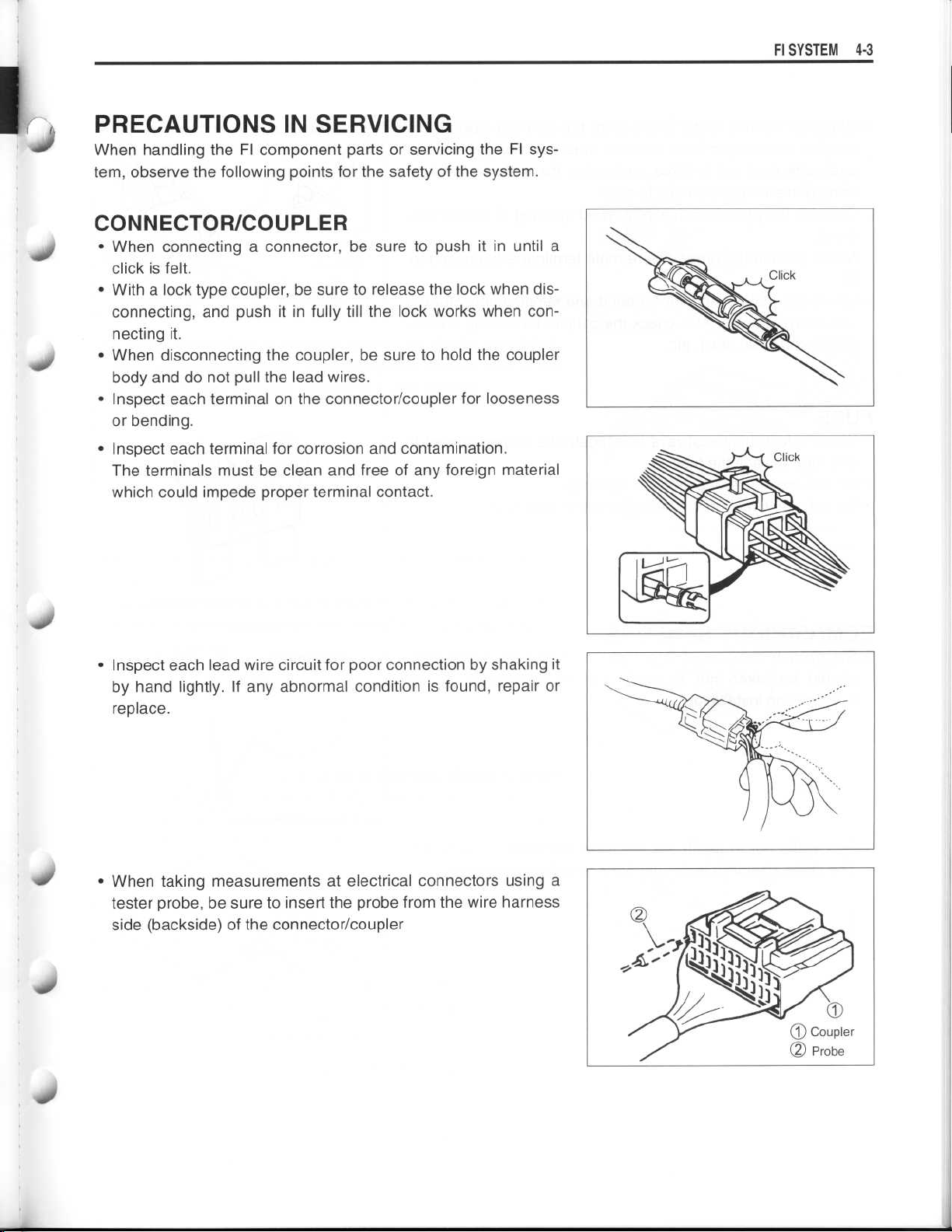
CONNECTOR/COUPLER
•
When connecting a connector, be sure to push it in until a
click is felt
•
With a lock type coupler, be sure to release the lock when disconnecting, and push it in fully till the lock works when connecting it
•
When disconnecting the coupler, be sure to hold the coupler
body and do not pull the lead wires
•
Inspect each terminal on the connector/coupler for looseness
or bending
•
Inspect each terminal for corrosion and contamination
The terminals must be clean and free of any foreign material
which could impede proper terminal contact
.
.
.
.
.
.
.
FI SYSTEM 4-
3
•
Inspect each lead wire circuit for poor connection by shaking it
by hand lightly . If any abnormal condition is found, repair or
replace
•
When taking measurements at electrical connectors using a
tester probe, be sure to insert the probe from the wire harness
side (backside) of the connector/coupler
.
Page 4
~
~
~
~
4
-4 Fl SYSTEM
•
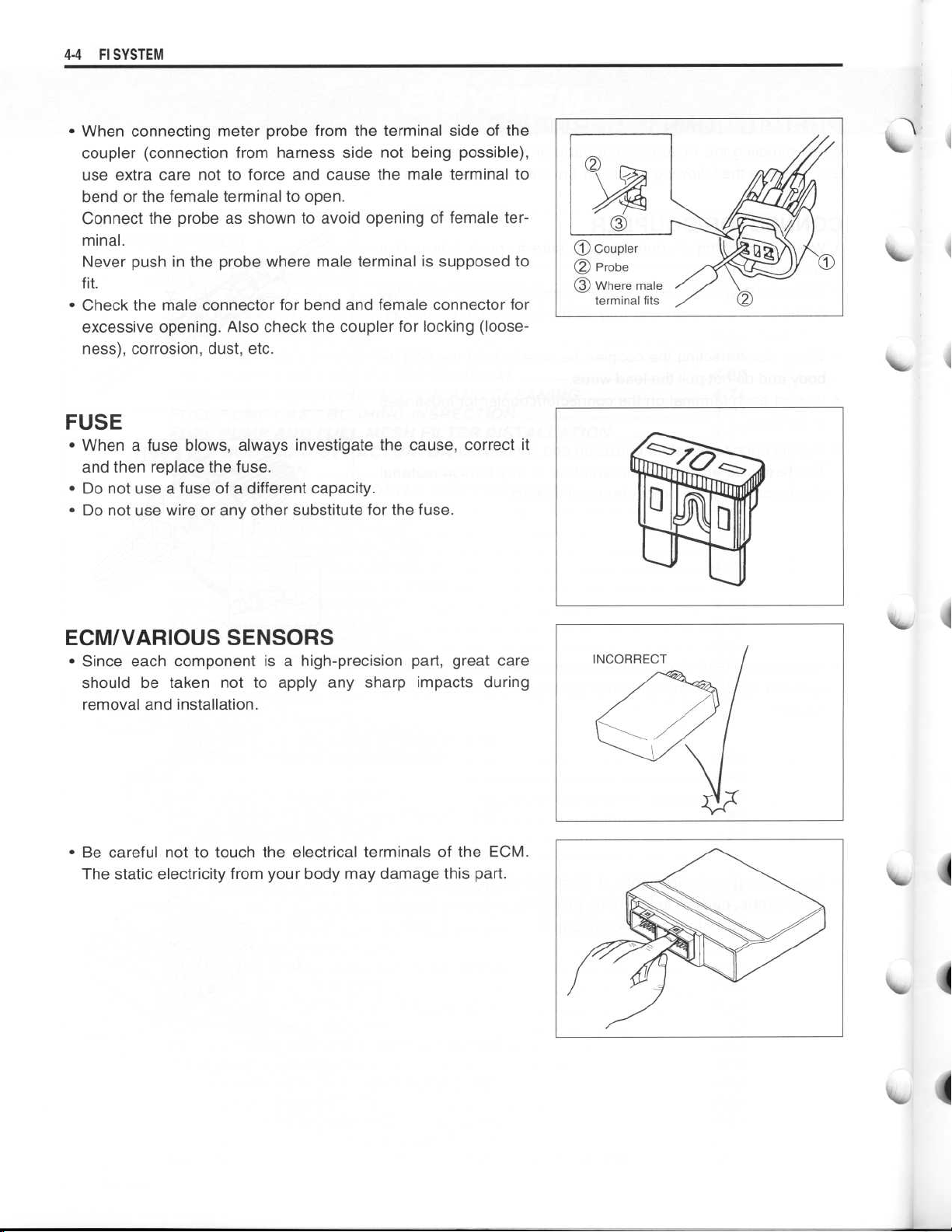
When connecting meter probe from the terminal side of the
coupler (connection from harness side not being possible),
use extra care not to force and cause the male terminal to
bend or the female terminal to open
Connect the probe as shown to avoid opening of female ter-
minal
.
Never push in the probe where male terminal is supposed to
.
fit
Check the male connector for bend and female connector for
•
excessive opening
ness), corrosion, dust, etc
. Also check the coupler for locking (loose-
.
.
FUSE
When a fuse blows, always investigate the cause, correct it
•
and then replace the fuse
Do not use a fuse of a different capacity
•
•
Do not use wire or any other substitute for the fuse
.
.
.
ECM/VARIOUS SENSORS
Since each component is a high-precision part, great care
•
should be taken not to apply any sharp impacts during
removal and installation
Be careful not to touch the electrical terminals of the ECM
•
The static electricity from your body may damage this part
.
.
.
I"
Page 5
~
FI SYSTEM4-5
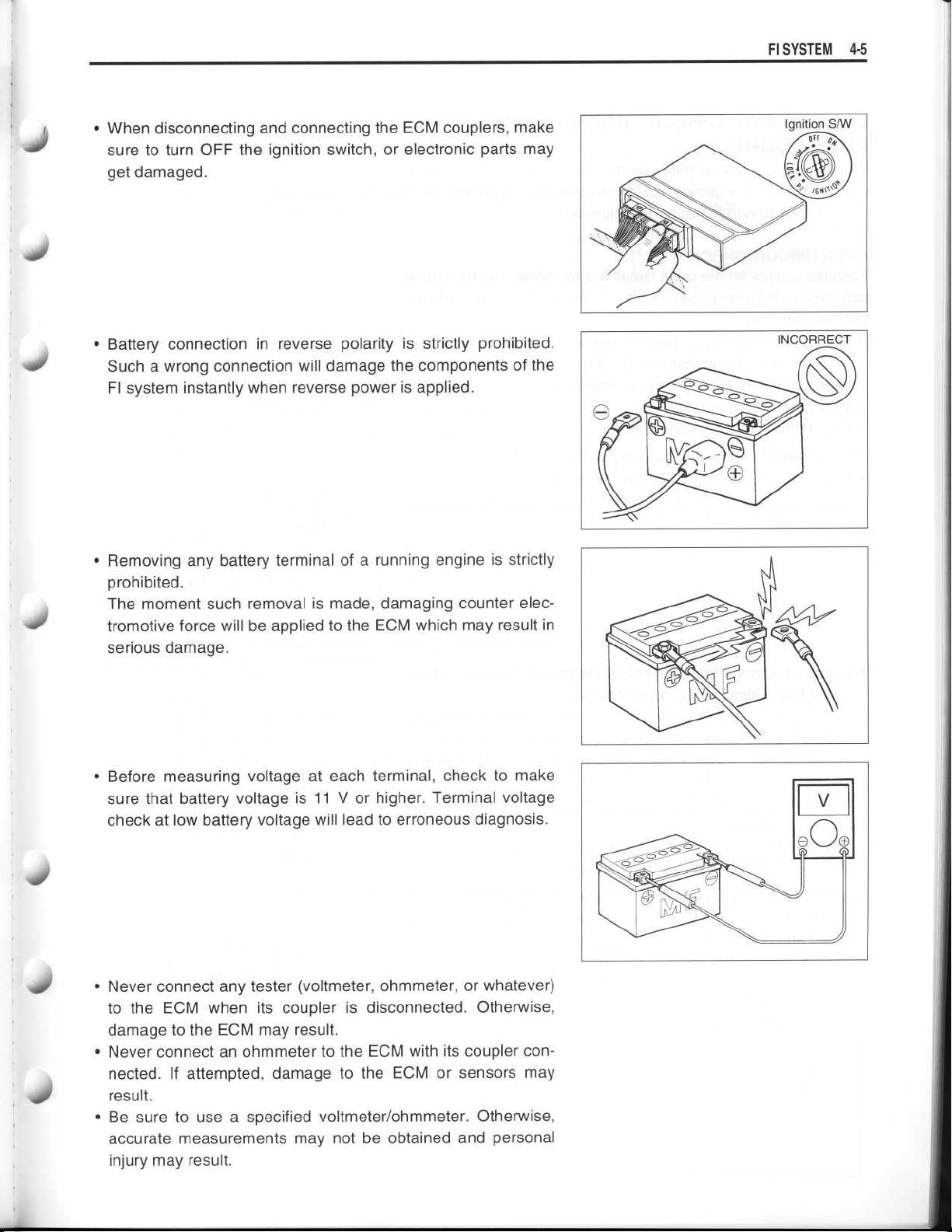
•
When disconnecting and connecting the ECM couplers, make
sure to turn OFF the ignition switch, or electronic parts may
get damaged
.
Battery connection in reverse polarity is strictly prohibited
•
Such a wrong connection will damage the components of the
FI system instantly when reverse power is applied
•
Removing any battery terminal of a running engine is strictly
prohibited
The moment such removal is made, damaging counter electromotive force will be applied to the ECM which may result in
serious damage
Before measuring voltage at each terminal, check to make
•
sure that battery voltage is 11 V or higher
check at low battery voltage will lead to erroneous diagnosis
.
.
. Terminal voltage
.
.
.
4
Never connect any tester (voltmeter, ohmmeter, or whatever)
•
to the ECM when its coupler is disconnected
damage to the ECM may result
Never connect an ohmmeter to the ECM with its coupler con-
•
nected
result
•
Be sure to use a specified voltmeter/ohmmeter
accurate measurements may not be obtained and personal
injury may result
. If attempted, damage to the ECM or sensors may
.
.
.
. Otherwise,
. Otherwise,
Page 6
~
~
~
~
~
~
~
4
-6 FI SYSTEM
ELECTRICAL CIRCUIT INSPECTION
PROCEDURE
While there are various methods for electrical circuit inspection,
described here is a general method to check for open and short
circuit using an ohmmeter and a voltmeter
OPEN CIRCUIT CHECK
Possible causes for the open circuit are as follows
can exist in the connector/coupler or terminal, they need to be
checked carefully
•
Loose connection of connector/coupler
•
Poor contact of terminal (due to dirt, corrosion or rust, poor
contact tension, entry of foreign object etc
•
Wire harness being open
•
Poor terminal-to-wire connection
.
.
. As the cause
.)
•
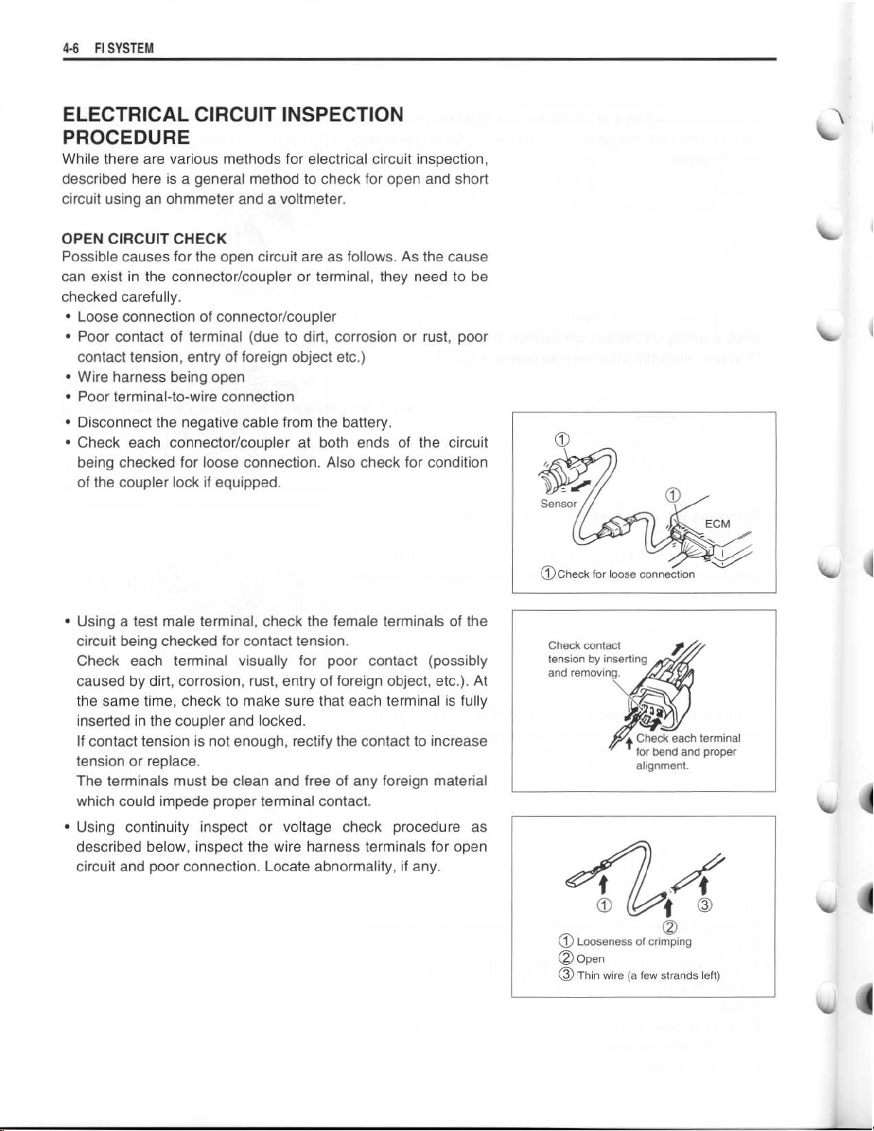
Disconnect the negative cable from the battery
•
Check each connector/coupler at both ends of the circuit
being checked for loose connection
of the coupler lock if equipped
Using a test male terminal, check the female terminals of the
•
circuit being checked for contact tension
Check each terminal visually for poor contact (possibly
caused by dirt, corrosion, rust, entry of foreign object, etc
the same time, check to make sure that each terminal is fully
inserted in the coupler and locked
If contact tension is not enough, rectify the contact to increase
tension or replace
The terminals must be clean and free of any foreign material
which could impede proper terminal contact
Using continuity inspect or voltage check procedure as
•
described below, inspect the wire harness terminals for open
circuit and poor connection
.
. Locate abnormality, if any
. Also check for condition
.
.
.
.
.)
. At
.
.
Check contact
tension by inserting
and removing
.
441
t
Check each terminal
for bend and proper
alignment
.
Page 7
~
~
~
~
~
~
~
~
~
FI SYSTEM 4-7
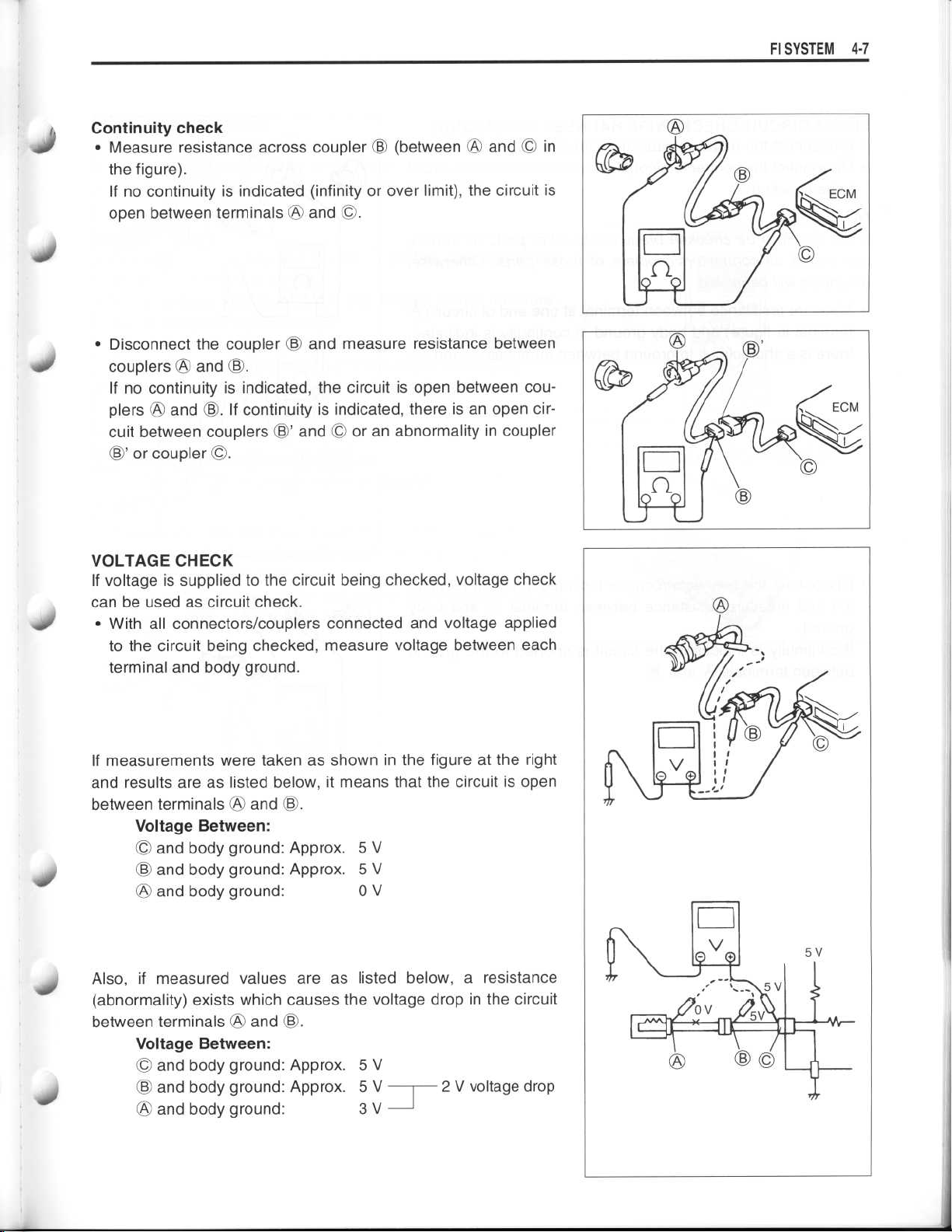
Continuity check
•
.-
S
Measure resistance across coupler © (between
the figure)
If no continuity is indicated (infinity or over limit), the circuit is
open between terminalsWOand ©
Disconnect the coupler © and measure resistance between
•
couplersWOand ©
If no continuity is indicated, the circuit is open between couplersWOand ©
cuit between couplers ©' and © or an abnormality in coupler
©' or coupler ©
.
.
.
. If continuity is indicated, there is an open cir-
.
and © in
WO
,,ill/
40
10
VOLTAGE CHECK
If voltage is supplied to the circuit being checked, voltage check
can be used as circuit check
•
With all connectors/couplers connected and voltage applied
to the circuit being checked, measure voltage between each
terminal and body ground
If measurements were taken as shown in the figure at the right
and results are as listed below, it means that the circuit is open
between terminals
Voltage Between
•
and body ground
•
and body ground
and body ground
•
Also, if measured values are as listed below, a resistance
(abnormality) exists which causes the voltage drop in the circuit
between terminalsWOand ©
Voltage Between
and body ground
•
•
and body ground
and body ground
•
WO
and ©
.
.
.
:
: Approx
: Approx
:
.
:
: Approx
: Approx
:
. 5 V
. 5 V
0 V
. 5 V
. 5 V
3 V
2 V voltage drop
Page 8
~
~
4-8 FI
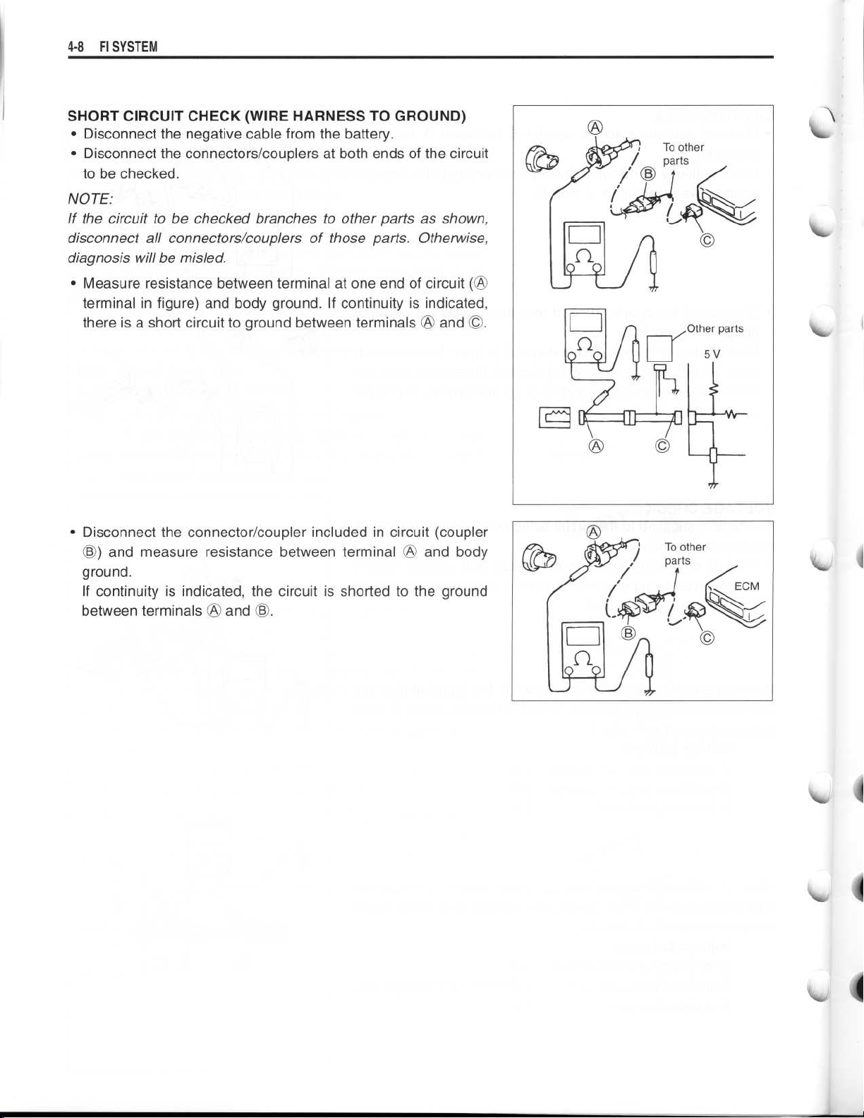
SHORT CIRCUIT CHECK (WIRE HARNESS TO GROUND)
NOTE
If the circuit to be checked branches to other parts as shown,
disconnect all connectors/couplers of those parts
diagnosis will be misled
SYSTEM
•
Disconnect the negative cable from the battery
•
Disconnect the connectors/couplers at both ends of the circuit
to be checked
:
•
Measure resistance between terminal at one end of circuit
terminal in figure) and body ground
there is a short circuit to ground between terminals
.
.
. If continuity is indicated,
.
. Otherwise,
and ©
OA
(A
.
•
Disconnect the connector/coupler included in circuit (coupler
©) and measure resistance between terminalOOand body
ground
If continuity is indicated, the circuit is shorted to the ground
between terminalsOand ©
.
.
Page 9
~
~
~
~
~
~
~
~
Fl SYSTEM 4-9
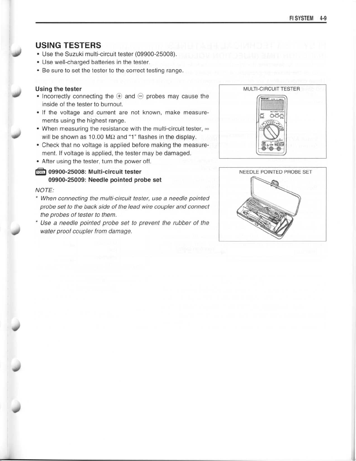
USING TESTERS
•
Use the Suzuki multi-circuit tester (09900-25008)
•
Use well-charged batteries in the tester
•
Be sure to set the tester to the correct testing range
Using the tester
•
Incorrectly connecting the (+ andOprobes may cause the
inside of the tester to burnout
•
If the voltage and current are not known, make measurements using the highest range
•
When measuring the resistance with the multi-circuit tester,
will be shown as 10
•
Check that no voltage is applied before making the measurement
. If voltage is applied, the tester may be damaged
•
After using the tester, turn the power off
.00 MS2 and "1" flashes in the display
.
.
.
.
.
.
.
.
40
40
Irs
09900-25008
09900-25009
NOTE
:
•
When connecting the multi-circuit tester, use a needle pointed
probe set to the back side of the lead wire coupler and connect
the probes of tester to them
* Use a needle pointed probe set to prevent the rubber of the
waterproof coupler from damage
: Multi-circuit tester
: Needle pointed probe set
.
.
q0
Page 10

~
4-10 FI SYSTEM
FI SYSTEM TECHNICAL FEATURES
INJECTION TIME (INJECTION VOLUME)
The factors to determine the injection time include the basic fuel injection time which is calculated on the
basis of the intake air pressure, engine speed and throttle opening angle, and various compensations
These compensations are determined according to the signals from various sensors that detect the engine
and driving conditions
.
.
-
Intake Air Pressure
Sensor (IAP Sensor)
~
Crankshaft Position
Sensor (CKP Sensor)
Throttle Position
Sensor (TP Sensor)
Various
Sensors
Injectors
Intake air pressure
signal
Engine speed
signal
Throttle opening
signal
Various signals
Injection signal
~
ECM
Basic
fuel
injection
time
Compensation
Ultimate
fuel
injection
time
- -
-t
44
Page 11
FI SYSTEM 4
.11
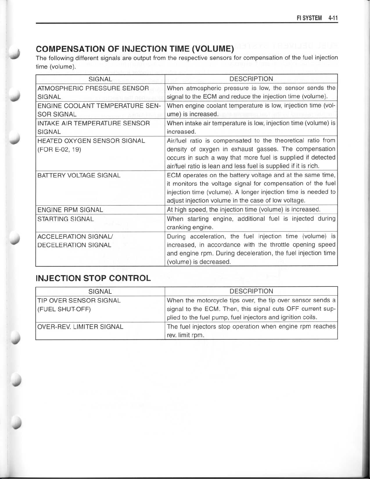
COMPENSATION OF INJECTION TIME (VOLUME)
The following different signals are output from the respective sensors for compensation of the fuel injection
time (volume)
.
S
S
SIGNAL
ATMOSPHERIC PRESSURE SENSOR
SIGNAL
ENGINE COOLANT TEMPERATURE SEW
SOR SIGNAL
INTAKE AIR TEMPERATURE SENSOR
SIGNAL
HEATED OXYGEN SENSOR SIGNAL
(FOR E-02,19)
BATTERY VOLTAGE SIGNAL
ENGINE RPM SIGNAL
STARTING SIGNAL
ACCELERATION SIGNAL/
DECELERATION SIGNAL
DESCRIPTION
When atmospheric pressure is low, the sensor sends the
signal to the ECM and reduce the injection time (volume)
When engine coolant temperature is low, injection time (volume) is increased
When intake air temperature is low, injection time (volume) is
increased
Air/fuel ratio is compensated to the theoretical ratio from
density of oxygen in exhaust gasses
occurs in such a way that more fuel is supplied if detected
air/fuel ratio is lean and less fuel is supplied if it is rich
ECM operates on the battery voltage and at the same time,
it monitors the voltage signal for compensation of the fuel
injection time (volume)
adjust injection volume in the case of low voltage
At high speed, the injection time (volume) is increased
When starting engine, additional fuel is injected during
cranking engine
During acceleration, the fuel injection time (volume) is
increased, in accordance with the throttle opening speed
and engine rpm
(volume) is decreased
.
.
. The compensation
. A longer injection time is needed to
.
.
. During deceleration, the fuel injection time
.
.
.
.
INJECTION STOP CONTROL
SIGNAL
TIP OVER SENSOR SIGNAL
(FUEL SHUT-OFF)
OVER-REV
. LIMITER SIGNAL
DESCRIPTION
When the motorcycle tips over, the tip over sensor sends a
signal to the ECM
plied to the fuel pump, fuel injectors and ignition coils
The fuel injectors stop operation when engine rpm reaches
. limit rpm
rev
. Then, this signal cuts OFF current sup-
.
.
Page 12
4
-12 Fl SYSTEM
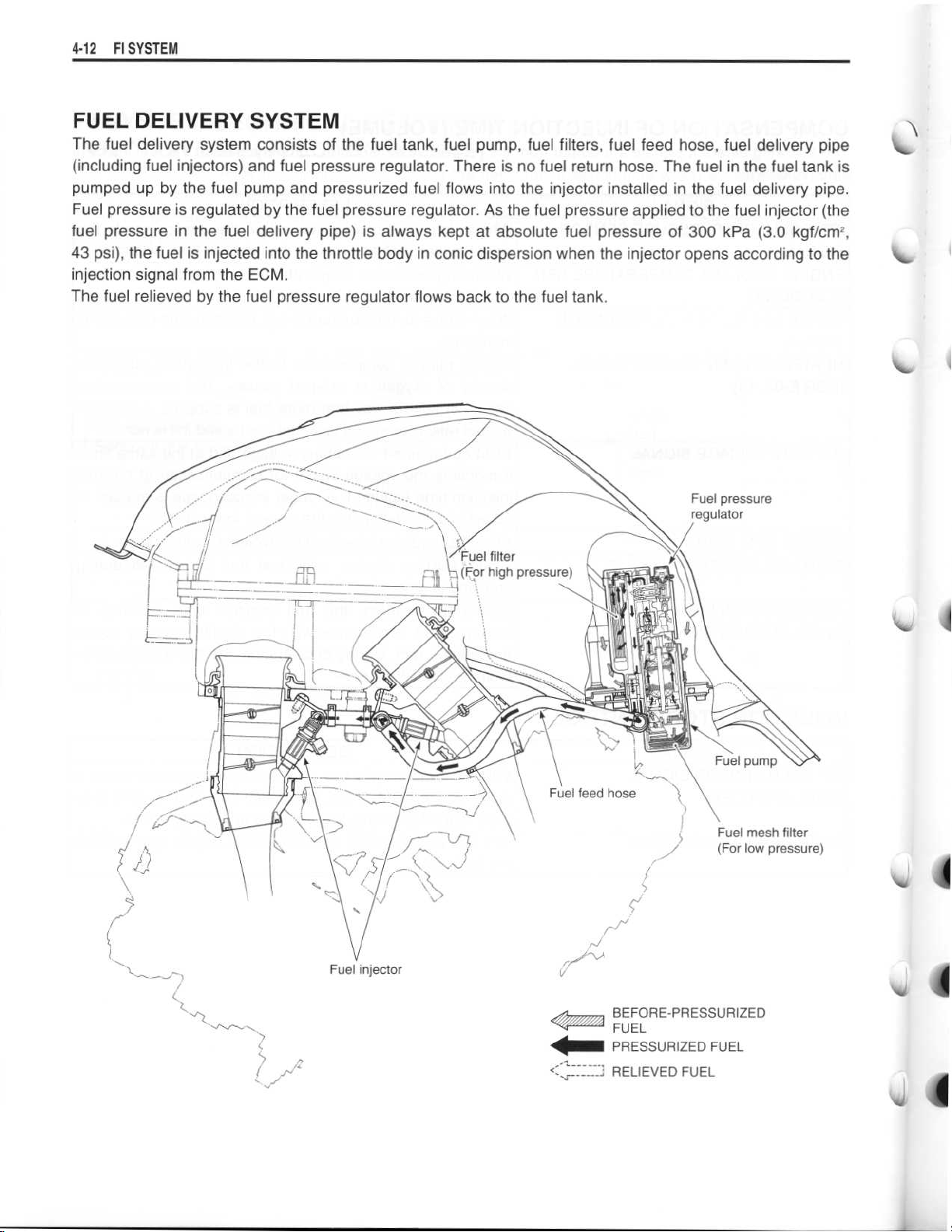
FUEL DELIVERY SYSTEM
The fuel delivery system consists of the fuel tank, fuel pump, fuel filters, fuel feed hose, fuel delivery pipe
(including fuel injectors) and fuel pressure regulator . There is no fuel return hose
pumped up by the fuel pump and pressurized fuel flows into the injector installed in the fuel delivery pipe
Fuel pressure is regulated by the fuel pressure regulator
. As the fuel pressure applied to the fuel injector (the
fuel pressure in the fuel delivery pipe) is always kept at absolute fuel pressure of 300 kPa (3
43 psi), the fuel is injected into the throttle body in conic dispersion when the injector opens according to the
injection signal from the ECM
The fuel relieved by the fuel pressure regulator flows back to the fuel tank
.
.
. The fuel in the fuel tank is
.
.0 kgf/cm2,
Fuel pressure
regulator
Fuel injector
BEFORE-PRESSURIZED
FUEL
PRESSURIZED FUEL
__~RELIEVED FUEL
Page 13
~
Fl SYSTEM 4
.13
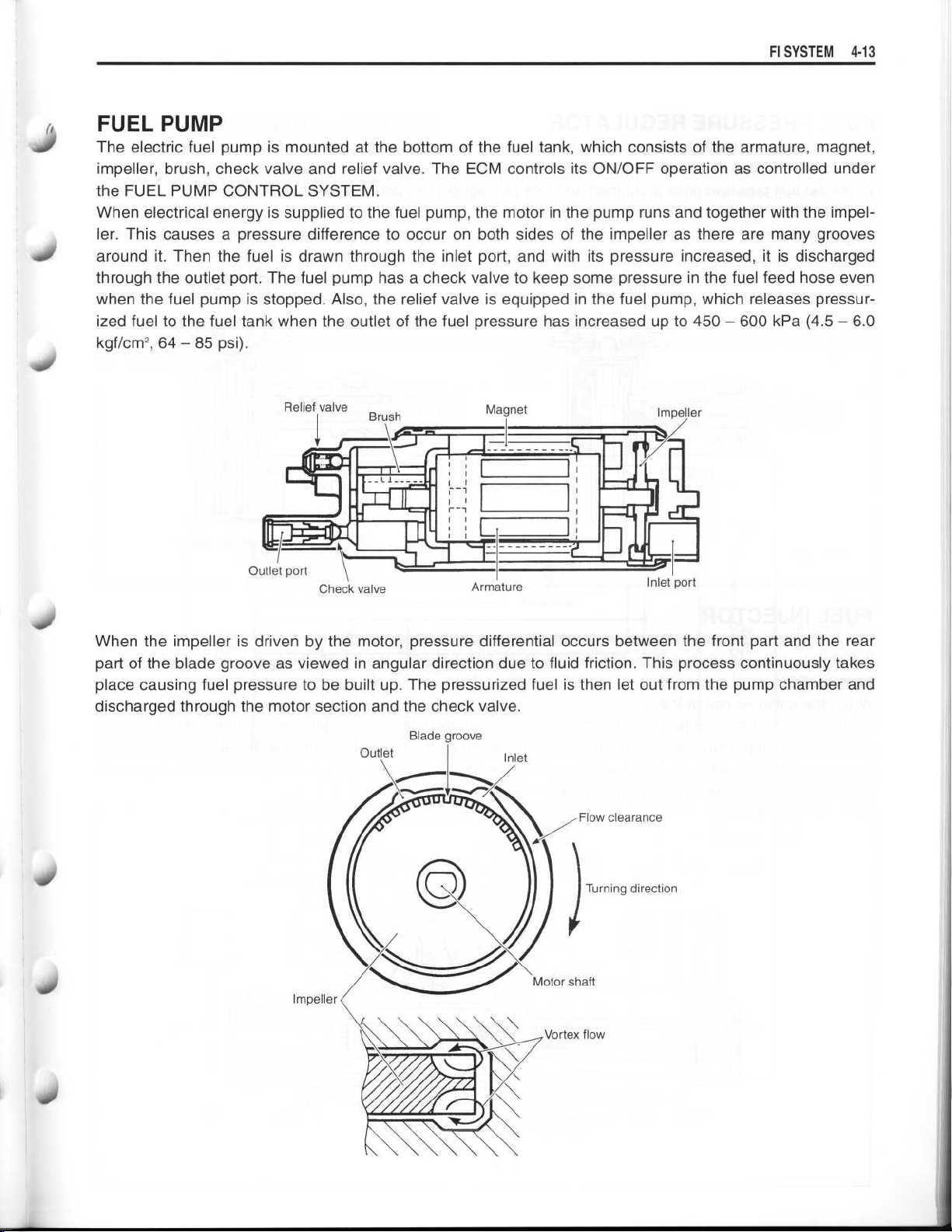
FUEL PUMP
The electric fuel pump is mounted at the bottom of the fuel tank, which consists of the armature, magnet,
impeller, brush, check valve and relief valve
the FUEL PUMP CONTROL SYSTEM
When electrical energy is supplied to the fuel pump, the motor in the pump runs and together with the impeller
. This causes a pressure difference to occur on both sides of the impeller as there are many grooves
around it
through the outlet port
when the fuel pump is stopped
. Then the fuel is drawn through the inlet port, and with its pressure increased, it is discharged
. The fuel pump has a check valve to keep some pressure in the fuel feed hose even
. Also, the relief valve is equipped in the fuel pump, which releases pressurized fuel to the fuel tank when the outlet of the fuel pressure has increased up to 450
kgf/cm2,
64
- 85 psi)
.
Relief valve
'∎
Brush
. The ECM controls its ON/OFF operation as controlled under
.
-
600 kPa (4.5-6.0
Magnet
I
Impeller
S
1
-71-
W1101
Check valve
When the impeller is driven by the motor, pressure differential occurs between the front part and the rear
part of the blade groove as viewed in angular direction due to fluid friction
place causing fuel pressure to be built up
discharged through the motor section and the check valve
. The pressurized fuel is then let out from the pump chamber and
Blade groove
Outlet
L_
Armature
Inlet
Inlet port
. This process continuously takes
.
40
Page 14
~
4-14 FI SYSTEM
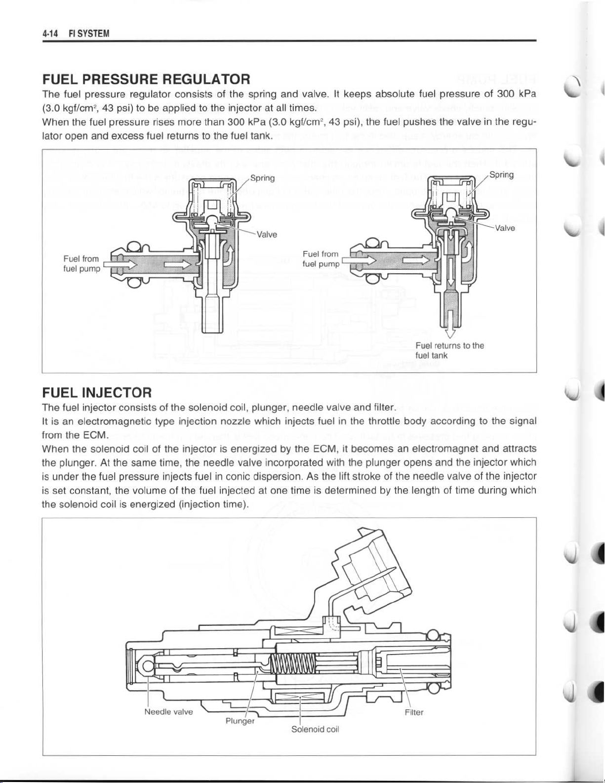
FUEL PRESSURE REGULATOR
The fuel pressure regulator consists of the spring and valve
(3
.0 kgf/cm2, 43 psi) to be applied to the injector at all times
When the fuel pressure rises more than 300 kPa (3
lator open and excess fuel returns to the fuel tank
.0 kgf/cm2,
.
. It keeps absolute fuel pressure of 300 kPa
.
43 psi), the fuel pushes the valve in the regu-
FUEL INJECTOR
The fuel injector consists of the solenoid coil, plunger, needle valve and filter
It is an electromagnetic type injection nozzle which injects fuel in the throttle body according to the signal
from the ECM
.
When the solenoid coil of the injector is energized by the ECM, it becomes an electromagnet and attracts
the plunger
is under the fuel pressure injects fuel in conic dispersion
. At the same time, the needle valve incorporated with the plunger opens and the injector which
. As the lift stroke of the needle valve of the injector
is set constant, the volume of the fuel injected at one time is determined by the length of time during which
the solenoid coil is energized (injection time)
.
.
u
10,
IV
1~
~
Needle valve
~
Plunger
1111110-
Filter
Solenoid coil
Page 15
~
~
~
~
~
Fl SYSTEM4-15
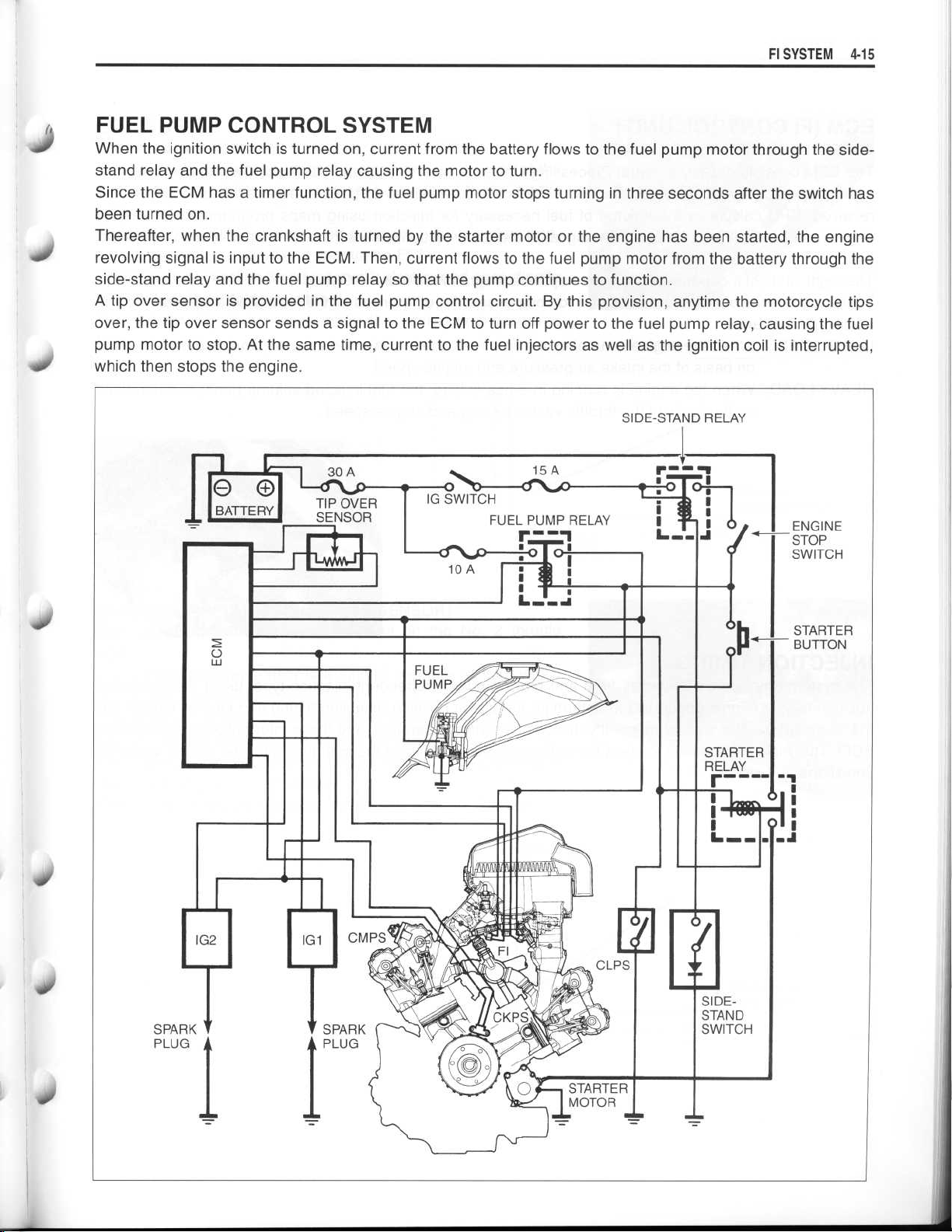
FUEL PUMP CONTROL SYSTEM
When the ignition switch is turned on, current from the battery flows to the fuel pump motor through the sidestand relay and the fuel pump relay causing the motor to turn
Since the ECM has a timer function, the fuel pump motor stops turning in three seconds after the switch has
been turned on
.
Thereafter, when the crankshaft is turned by the starter motor or the engine has been started, the engine
revolving signal is input to the ECM
. Then, current flows to the fuel pump motor from the battery through the
side-stand relay and the fuel pump relay so that the pump continues to function
A tip over sensor is provided in the fuel pump control circuit . By this provision, anytime the motorcycle tips
over, the tip over sensor sends a signal to the ECM to turn off power to the fuel pump relay, causing the fuel
pump motor to stop
which then stops the engine
. At the same time, current to the fuel injectors as well as the ignition coil is interrupted,
.
.
.
SIDE-STAND RELAY
O O
BATTERY
30A
TIP OVER
SENSOR
15A
IG SWITCH
FUEL PUMP RELAY
to
Page 16
4-16 FI SYSTEM
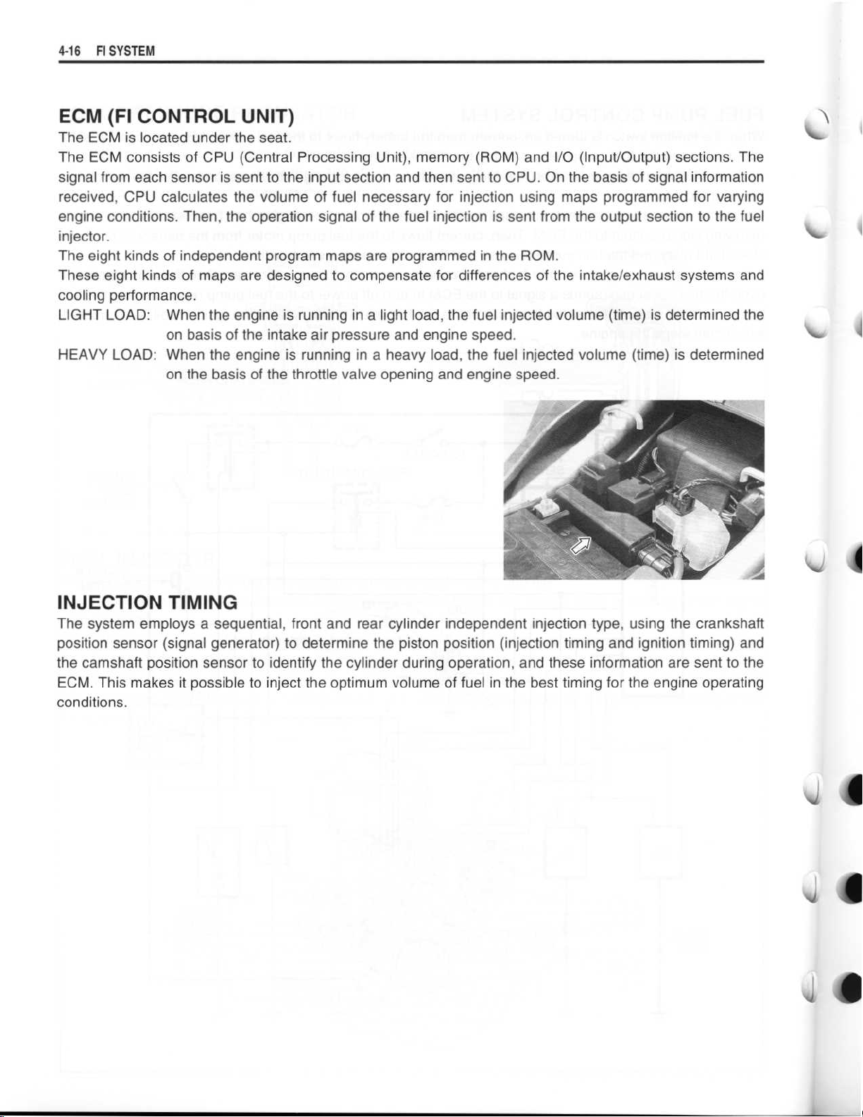
ECM (FI CONTROL UNIT)
The ECM is located under the seat
The ECM consists of CPU (Central Processing Unit), memory (ROM) and I/O (Input/Output) sections
signal from each sensor is sent to the input section and then sent to CPU
received, CPU calculates the volume of fuel necessary for injection using maps programmed for varying
engine conditions
injector
The eight kinds of independent program maps are programmed in the ROM
These eight kinds of maps are designed to compensate for differences of the intake/exhaust systems and
cooling performance
LIGHT LOAD:When the engine is running in a light load, the fuel injected volume (time) is determined the
HEAVY LOAD
.
. Then, the operation signal of the fuel injection is sent from the output section to the fuel
.
on basis of the intake air pressure and engine speed
: When the engine is running in a heavy load, the fuel injected volume (time) is determined
on the basis of the throttle valve opening and engine speed
.
. The
. On the basis of signal information
.
.
.
INJECTION TIMING
The system employs a sequential, front and rear cylinder independent injection type, using the crankshaft
position sensor (signal generator) to determine the piston position (injection timing and ignition timing) and
the camshaft position sensor to identify the cylinder during operation, and these information are sent to the
ECM
. This makes it possible to inject the optimum volume of fuel in the best timing for the engine operating
conditions
.
J
is
Page 17
SENSORS
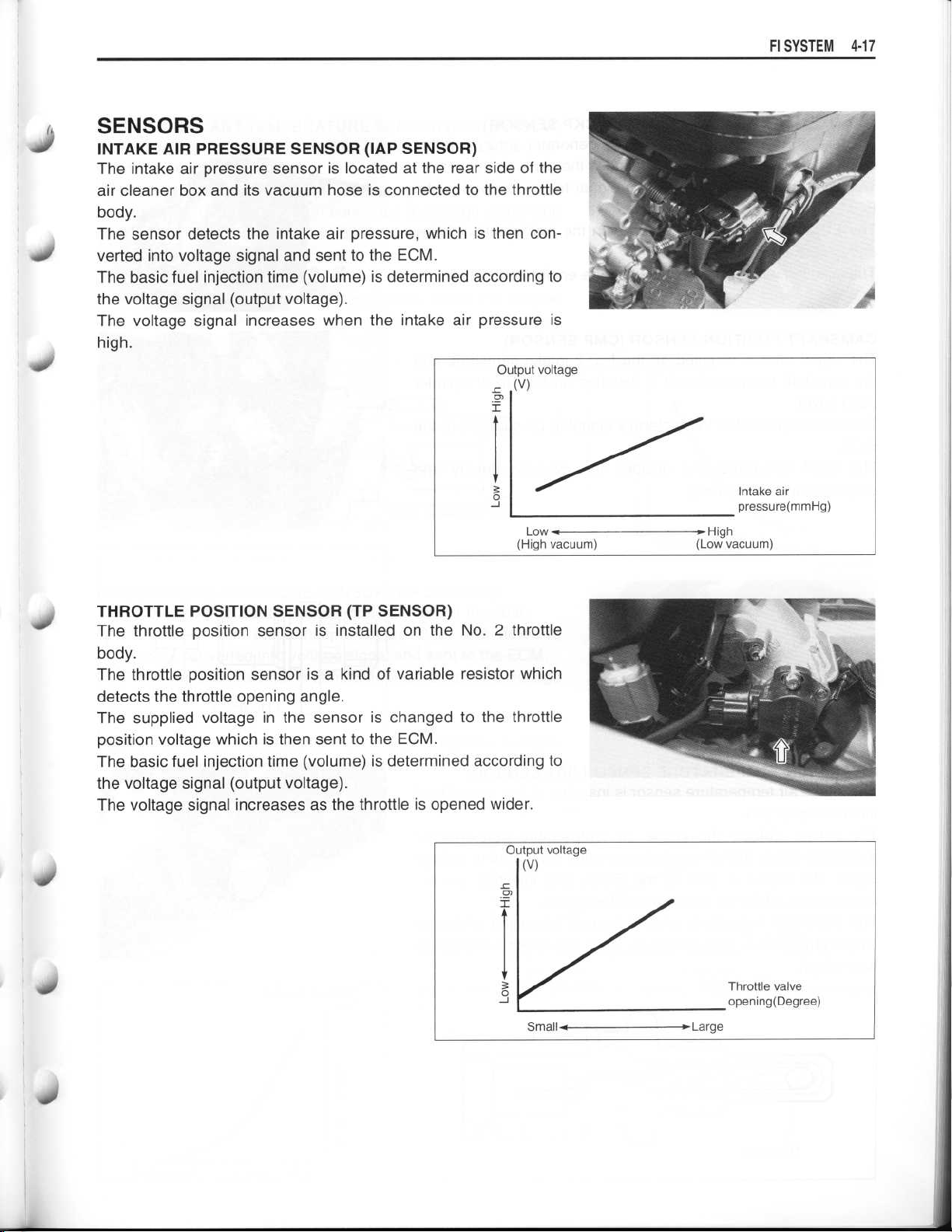
INTAKE AIR PRESSURE SENSOR (IAP SENSOR)
The intake air pressure sensor is located at the rear side of the
air cleaner box and its vacuum hose is connected to the throttle
body
.
The sensor detects the intake air pressure, which is then converted into voltage signal and sent to the ECM
The basic fuel injection time (volume) is determined according to
the voltage signal (output voltage)
The voltage signal increases when the intake air pressure is
high
.
.
.
FI SYSTEM 4-17
THROTTLE POSITION SENSOR (TP SENSOR)
The throttle position sensor is installed on the No
body
.
The throttle position sensor is a kind of variable resistor which
detects the throttle opening angle
The supplied voltage in the sensor is changed to the throttle
position voltage which is then sent to the ECM
The basic fuel injection time (volume) is determined according to
the voltage signal (output voltage)
The voltage signal increases as the throttle is opened wider
.
.
.
. 2 throttle
.
Page 18
4-18
FI SYSTEM
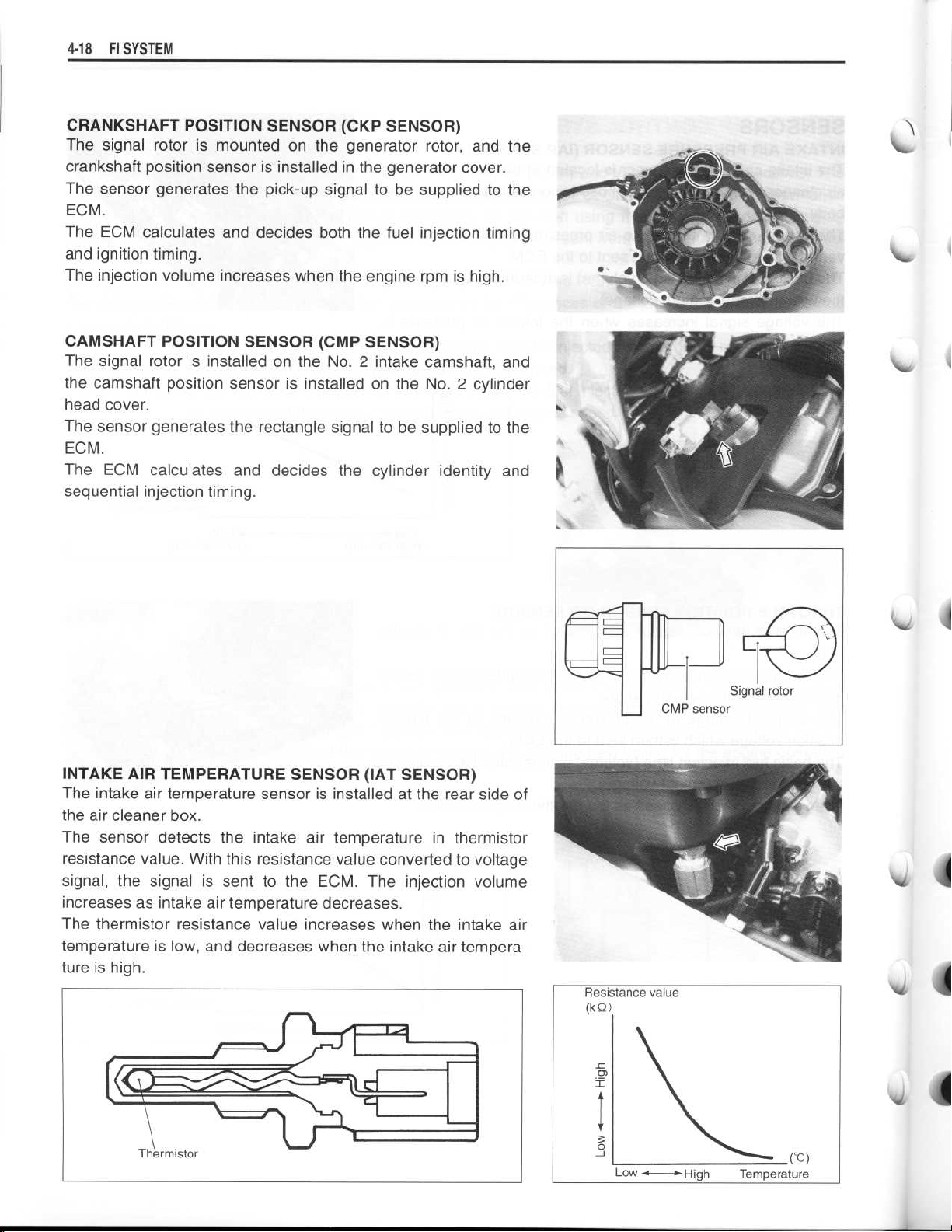
CRANKSHAFT POSITION SENSOR (CKP SENSOR)
The signal rotor is mounted on the generator rotor, and the
crankshaft position sensor is installed in the generator cover
.
The sensor generates the pick-up signal to be supplied to the
ECM
.
The ECM calculates and decides both the fuel injection timing
and ignition timing
The injection volume increases when the engine rpm is high
.
.
CAMSHAFT POSITION SENSOR (CMP SENSOR)
The signal rotor is installed on the No
the camshaft position sensor is installed on the No
head cover
.
. 2 intake camshaft, and
. 2 cylinder
The sensor generates the rectangle signal to be supplied to the
ECM
.
The ECM calculates and decides the cylinder identity and
sequential injection timing
.
CMP sensor
INTAKE AIR TEMPERATURE SENSOR (IAT SENSOR)
The intake air temperature sensor is installed at the rear side of
the air cleaner box
.
The sensor detects the intake air temperature in thermistor
resistance value
signal, the signal is sent to the ECM
increases as intake air temperature decreases
. With this resistance value converted to voltage
. The injection volume
.
The thermistor resistance value increases when the intake air
temperature is low, and decreases when the intake air tempera-
ture is high
.
10
~
1
Signal rotor
Thermistor
Page 19
FI SYSTEM 4-19
(I
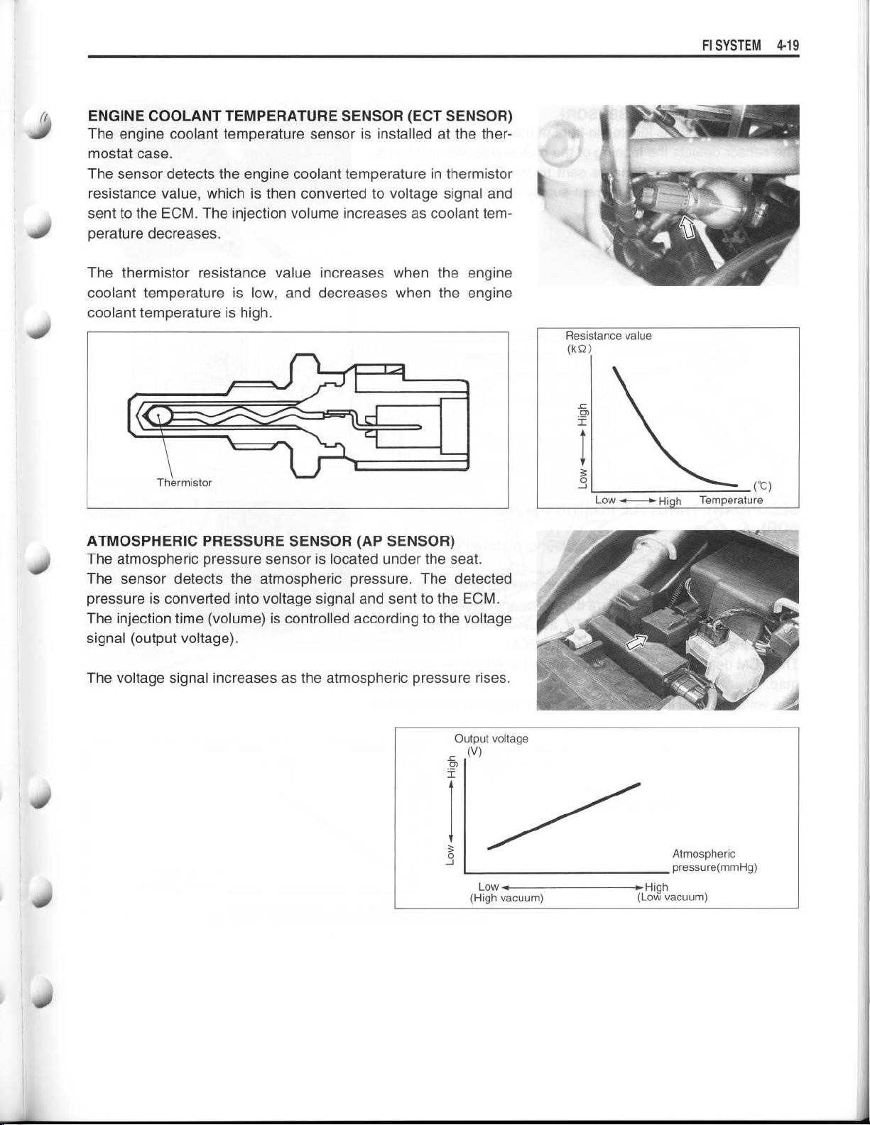
ENGINE COOLANT TEMPERATURE SENSOR (ECT SENSOR)
The engine coolant temperature sensor is installed at the ther-
mostat case
.
The sensor detects the engine coolant temperature in thermistor
resistance value, which is then converted to voltage signal and
sent to the ECM
perature decreases
. The injection volume increases as coolant tem-
.
The thermistor resistance value increases when the engine
coolant temperature is low, and decreases when the engine
coolant temperature is high
Thermistor
.
10
ATMOSPHERIC PRESSURE SENSOR (AP SENSOR)
The atmospheric pressure sensor is located under the seat
The sensor detects the atmospheric pressure
. The detected
pressure is converted into voltage signal and sent to the ECM
.
.
The injection time (volume) is controlled according to the voltage
signal (output voltage)
The voltage signal increases as the atmospheric pressure rises
.
.
Page 20
4-20 Fl
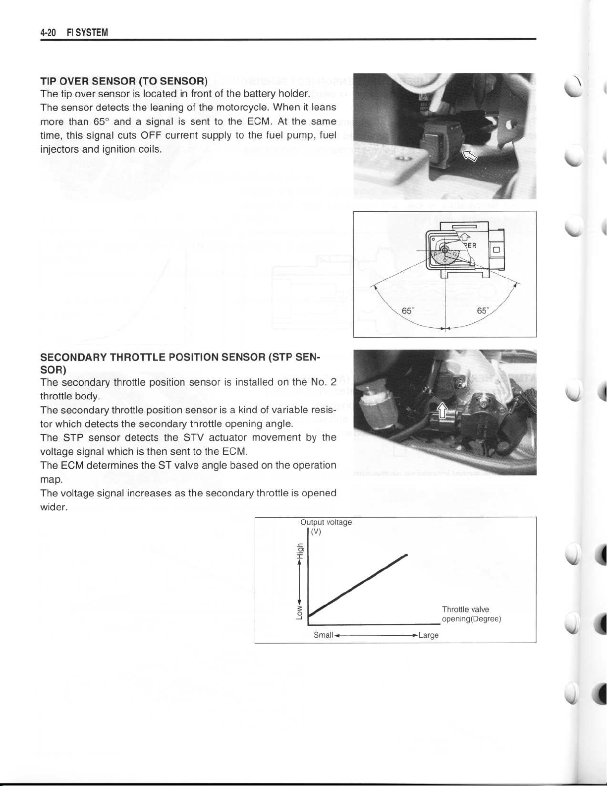
TIP OVER SENSOR (TO SENSOR)
The tip over sensor is located in front of the battery holder
The sensor detects the leaning of the motorcycle
more than 65° and a signal is sent to the ECM . At the same
time, this signal cuts OFF current supply to the fuel pump, fuel
injectors and ignition coils
SYSTEM
.
. When it leans
.
NNW
SECONDARY THROTTLE POSITION SENSOR (STP SENSOR)
The secondary throttle position sensor is installed on the No
throttle body
The secondary throttle position sensor is a kind of variable resistor which detects the secondary throttle opening angle
The STP sensor detects the STV actuator movement by the
voltage signal which is then sent to the ECM
The ECM determines the ST valve angle based on the operation
map
.
The voltage signal increases as the secondary throttle is opened
wider
.
.
.
.
. 2
4
Page 21
FI SYSTEM 4-
2
1
0
.r
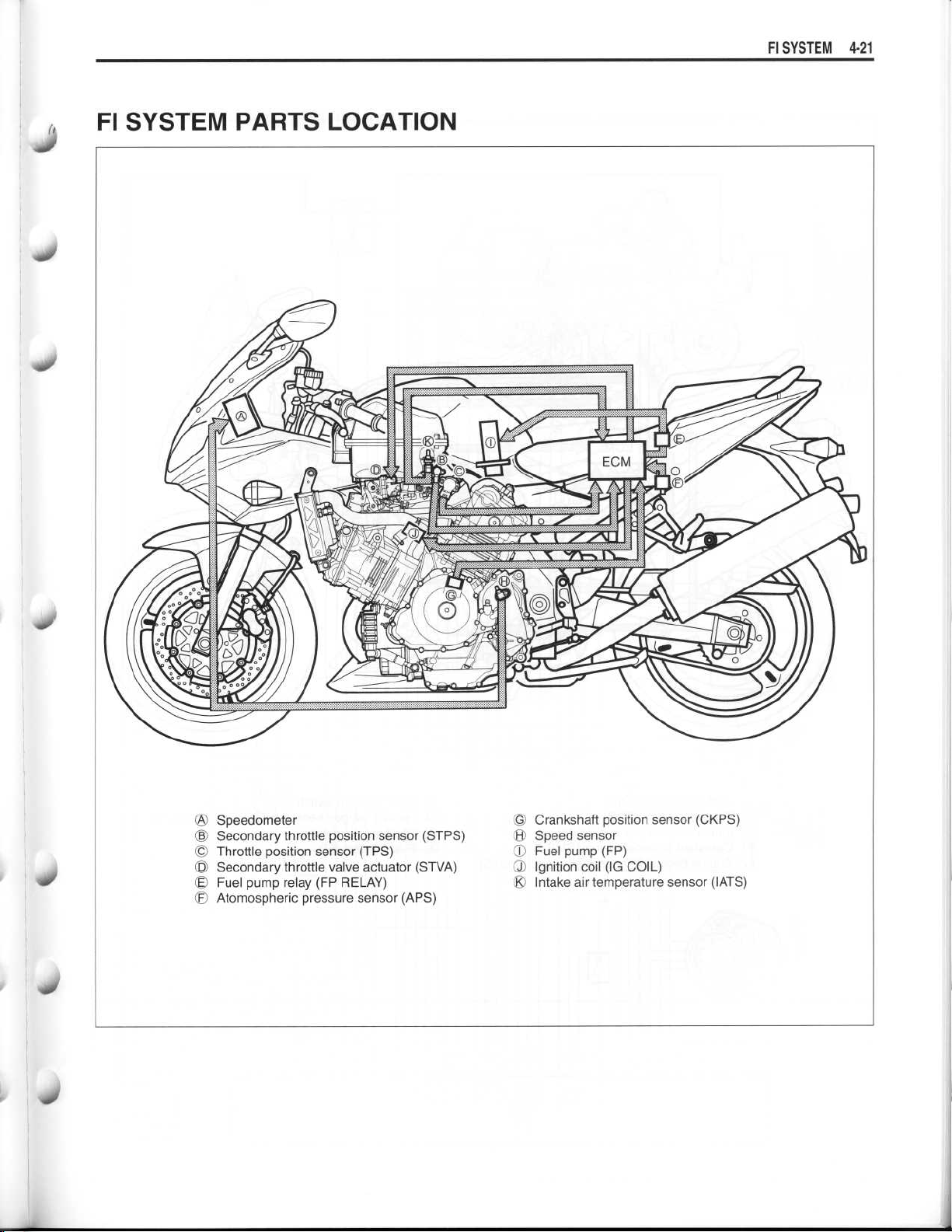
FI SYSTEM PARTS LOCATION
Speedometer
OA
©
Secondary throttle position sensor (STPS)®Speed sensor
Throttle position sensor (TPS)
©
Secondary throttle valve actuator (STVA)©Ignition coil (IG COIL)
©
©OFFuel pump relay (FP RELAY)
Atmospheric pressure sensor (APS)
©
Crankshaft position sensor (CKPS)
Fuel pump (FP)
O
®
Intake air temperature sensor (IATS)
Page 22
~
~
~
~
~
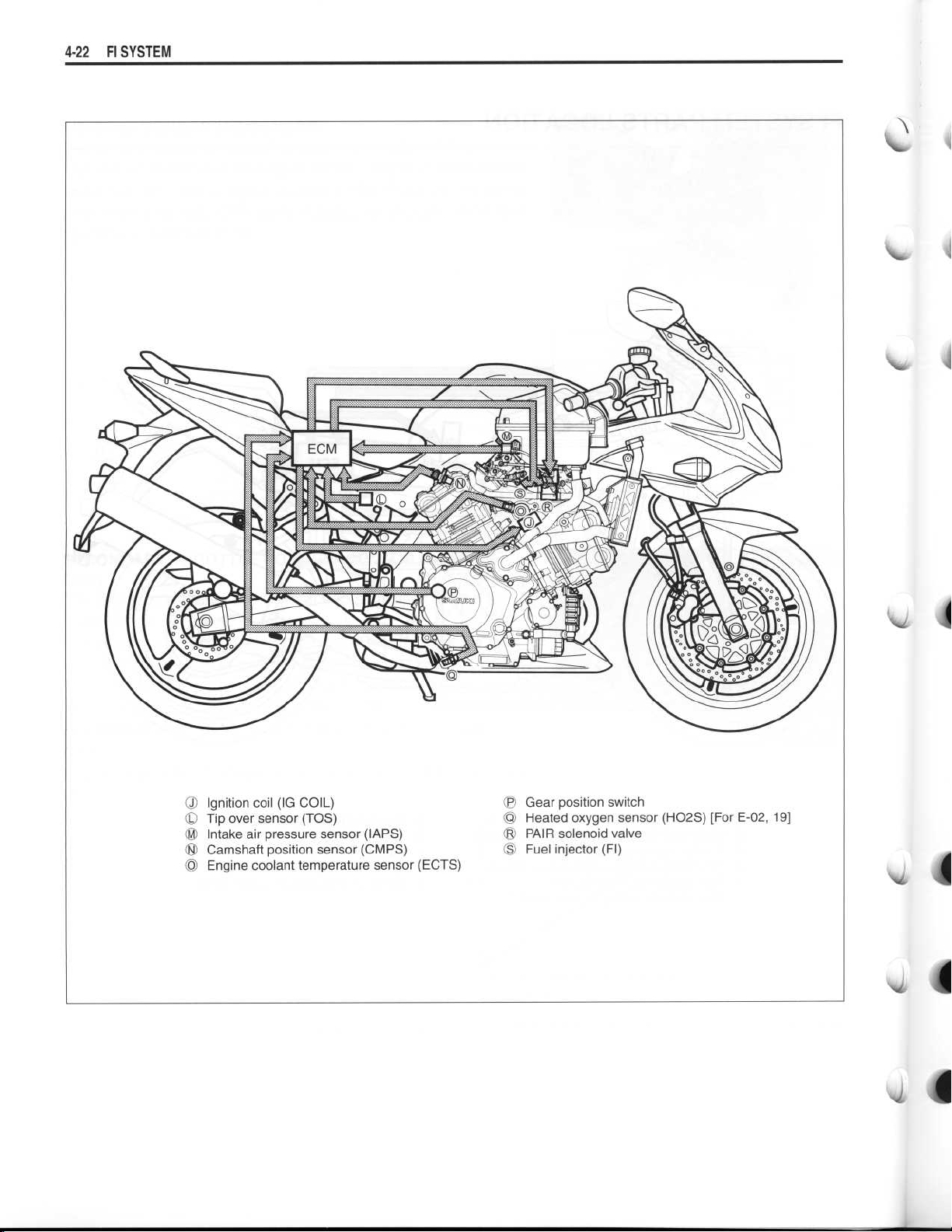
4-22
FI SYSTEM
Ignition coil (IG COIL)
•
•
Tip over sensor (TOS)
Intake air pressure sensor (ZAPS)
•
•
Camshaft position sensor (CMPS)
•
Engine coolant temperature sensor (ECTS)
® Gear position switch
® Heated oxygen sensor (HO2S) [For E-02, 19]
® PAIR solenoid valve
Fuel injector (FI)
OO
Page 23
~
~
SIDE-STAND ENGINE STOP
_RELAY
SWITCH
ECM
4-
C
H02 (OXH)
C
H02 (OX)
4
© TECH
BATT
OO
2
,
FP
TOS
© AT
'f$ +B
CLT
G1
1
0
G2
VM
THW
SOL
5 FI #1
CFI#2
© STA
3
MO+
© MO-
94 THA
VCC
v TPS
E2
STPS
G+
GP
N+
N-
T S
1e` PM
,It PA
TACO
4© NT
C
C13
©
-
Br
-Gr/W
- Gr/B
-
Y/G
-
B/R
-
R/B
Dg
-R
-P/W
-B/Br
-Y
-
W/B
- W/G
-
Y/W
MODE SELECTION SWITCH
1
IG1
1
10A
TIP OVER SENSOR
ATMOSPHERIC
PRESSURE
SENSOR
NEUTRAL
LAMP
FUEL PUMP RELAY
IL
O
h
STARTER
Y BUTTON
FUEL PUMP
CMPS
TPS
STPS
7
FI
FI
ECTS
.
y
SPEEDOMETER
0
INTAKE AIR
INTAKE
PRESSURE
SENSOR
PAIR SOLENOID
CONTROL VALVE
GEAR
SIDE-
POSITION LEVER
STAND
SWITCH SWITCH
CLUTCH
POSITION
SWITCH
H02SENSOR
(Except for USA)
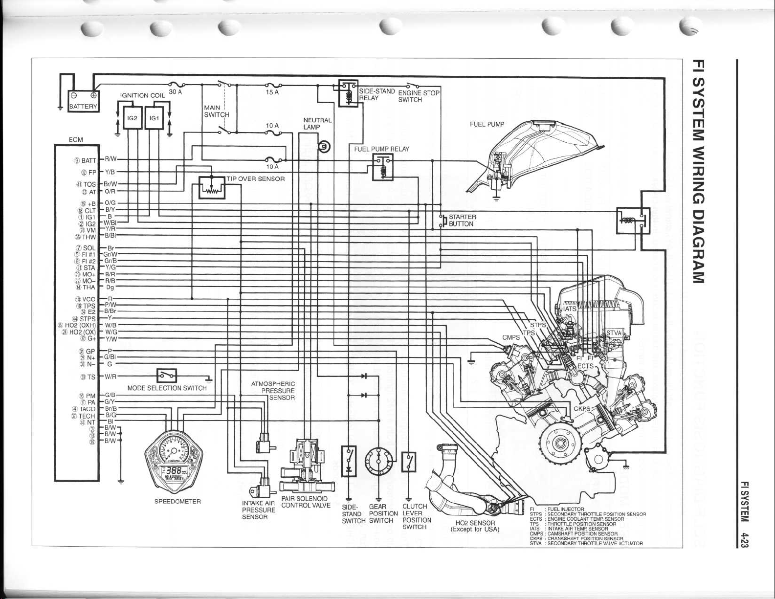
FI~FUEL INJECTOR
STPS SECONDARY THROTTLE POSITION SENSOR
ECTS ENGINE COOLANT TEMP
TPS
THROTTLE POSITION SENSOR
IATS
INTAKE AIR TEMP SENSOR
CMPS CAMSHAFT POSITION SENSOR
CKPS CRANKSHAFT POSITION SENSOR
STVA
SECONDARY THROTTLE VALVE ACTUATOR
. SENSOR
Page 24

4-24 FI SYSTEM
SELF-DIAGNOSIS FUNCTION
The self-diagnosis function is incorporated in the ECM
"Dealer mode"
. The user can only be notified by the LCD (DISPLAY) panel and FI light
tion of the individual FI system devices, the dealer mode is prepared
sary to read the code of the malfunction items
USER MODE
.
. The function has two modes, "User mode" and
. In this check, the special tool is neces-
. To check the func-
MALFUNCTION
"NO"
"YES"
LCD (DISPLAY)
INDICATION
Engine coolant
temp
.
Engine coolant
temp
. and "Fl"
letters
Engine can start
*
.
1
Engine can not start."Fl" letters*2"Fl" letter turns
*
1
When one of the signals is not received by the ECM, the fail-safe circuit works and injection is not stopped
In this case, "Fl" and engine coolant temp
. are indicated in the LCD panel and motorcycle can run
LCD (DISPLAY)
DA
INDICATION ©
"Fl" letter turns
ON
.
ON and blinks
FI LIGHT
INDICATION
FI light turns
ON
.
FI light turns ON
.
and blinks
.
INDICATION
CC
;
MODE
Each 2 sec
.
Engine coolant
temp
. or "Fl" is
indicated
.
"Fl" is indicated
continuously
.
.
.
*2
The injection signal is stopped, when the camshaft position sensor signal, crankshaft position sensor signal,
tip over sensor signal, both #1/#2 ignition signals, both #1/#2 injection signals, fuel pump relay signal or ignition switch signal is not sent to the ECM
.
run
"CHEC"
: The LCD panel indicates "CHEC" when no communication signal from the ECM is received for
5 seconds
For Example
.
:
The ignition switch is turned ON, and the engine stop switch is turned OFF
ometer does not receive any signal from the ECM, and the panel indicates "CHEC"
If "CHEC" is indicated, the LCD does not indicate the trouble code
ing harness between ECM and speedometer couplers
The possible cause of this indication is as follows
stand/ignition inter-lock system is not working
. In this case, "Fl" is indicated in the LCD panel
. Motorcycle does not
. In this case, the speed-
.
. It is necessary to check the wir-
.
; Engine stop switch is in OFF position
. Ignition fuse is burnt
.
. Side-
N
Page 25
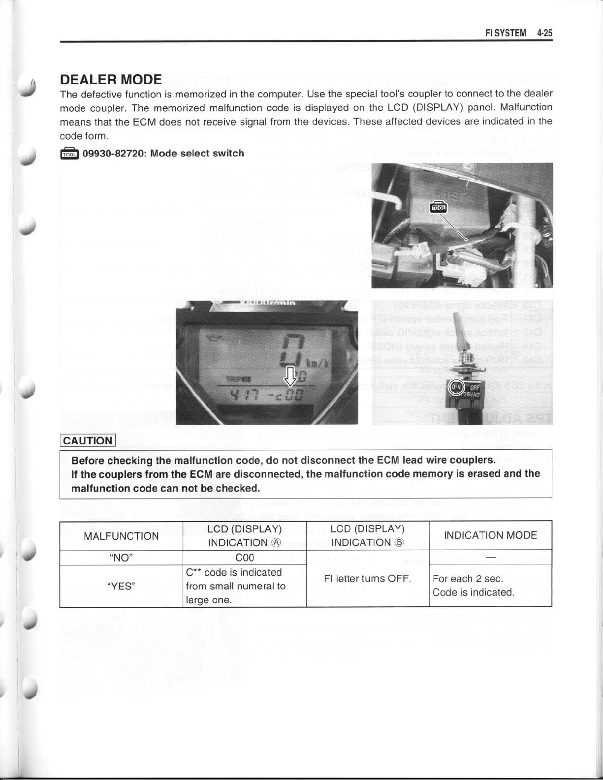
DEALER MODE
The defective function is memorized in the computer
mode coupler
means that the ECM does not receive signal from the devices
code form
.
•
09930-82720
. The memorized malfunction code is displayed on the LCD (DISPLAY) panel
.
: Mode select switch
. Use the special tool's coupler to connect to the dealer
. These affected devices are indicated in the
FI SYSTEM4-25
. Malfunction
40
CAUTION
Before checking the malfunction code, do not disconnect the ECM lead wire couplers
If the couplers from the ECM are disconnected, the malfunction code memory is erased and the
malfunction code can not be checked
MALFUNCTION
"NO"
"YES"
LCD (DISPLAY)
INDICATION
C** code is indicated
from small numeral to
large one
.
C00
.
LCD (DISPLAY)
INDICATION
FI letter turns OFF.For each 2 sec
INDICATION MODE
Code is indicated
.
-
.
.
Page 26
4-26 FI SYSTEM
CODE
COO
C11
C12
C13
C14
C15
C21
C22
C23
C24
C25
C28
C29
C31
C32
C33
C41
C42
C44
C49
MALFUNCTION PART
None
No defective part
Camshaft position sensor (CMPS)
Crankshaft position sensor (CKPS)
Pick-up coil signal, signal generator
Intake air pressure sensor (ZAPS)
Throttle position sensor (TPS)
Engine coolant temp
Intake air temp
. sensor (ECTS)
. sensor (IATS)
Atmospheric pressure sensor (APS)
Tip over sensor (TOS)
Ignition signal #1 (IG coil #1)
Ignition signal #2 (IG coil #2)
For #1 cylinder
For #2 cylinder
Secondary throttle valve actuator (STVA)
Secondary throttle valve position sensor
Gear position signal (GP switch)
Injector signal #1 (FI #1)
Injector signal #2 (F1 #2)
Fuel pump control system (FP control system)
Ignition switch signal (IG switch signal)
Heated oxygen sensor (HO2S)
For #1 cylinder
For #2 cylinder
Fuel pump, fuel pump relay
Anti-theft
For E-02, 19
PAIR control solenoid valve (PAIR valve)
REMARKS
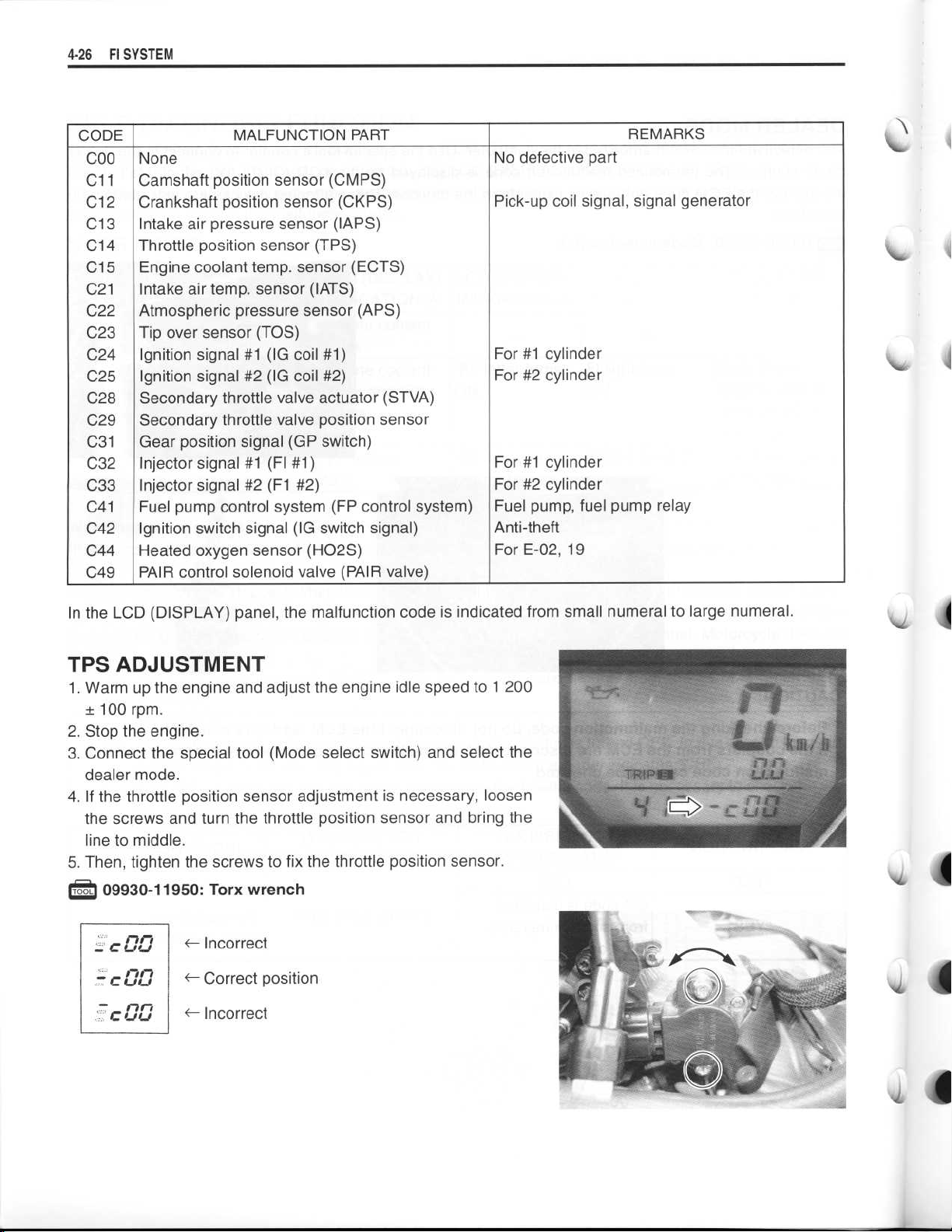
In the LCD (DISPLAY) panel, the malfunction code is indicated from small numeral to large numeral
.
TPS ADJUSTMENT
. Warm up the engine and adjust the engine idle speed to 1 200
1
± 100 rpm
. Stop the engine
2
. Connect the special tool (Mode select switch) and select the
3
dealer mode
. If the throttle position sensor adjustment is necessary, loosen
4
the screws and turn the throttle position sensor and bring the
line to middle
. Then, tighten the screws to fix the throttle position sensor
5
.
.
09930-11950
C L/
C
r_ %i(J
U %
J
.
.
.
.
: Torx wrench
-
Incorrect
Correct position
-
~- Incorrect
.
Page 27
40
FI SYSTEM 4-
2 7
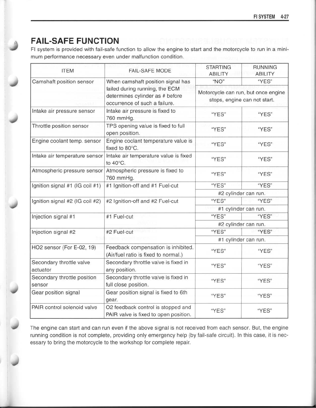
FAIL-SAFE FUNCTION
FI system is provided with fail-safe function to allow the engine to start and the motorcycle to run in a mini-
mum performance necessary even under malfunction condition
.
ITEM
Camshaft position sensor
Intake air pressure sensor
Throttle position sensor
Engine coolant temp
Intake air temperature sensor
Atmospheric pressure sensor
Ignition signal #1 (IG coil #1)
Ignition signal #2 (IG coil #2)
Injection signal #1
Injection signal #2
H02 sensor (For E-02, 19) Feedback compensation is inhibited
Secondary throttle valve
actuator
Secondary throttle position
sensor
Gear position signal
PAIR control solenoid valve
. sensor
When camshaft position signal has
failed during running, the ECM
determines cylinder as # before
occurrence of such a failure
Intake air pressure is fixed to
760 mmHg
TPS opening value is fixed to full
open position
Engine coolant temperature value is
fixed to 80°C
Intake air temperature value is fixed
to 40°C
Atmospheric pressure is fixed to
760 mmHg
#1 Ignition-off and #1 Fuel-cut
#2 Ignition-off and #2 Fuel-cut
#1 Fuel-cut
#2 Fuel-cut
(Air/fuel ratio is fixed to normal
Secondary throttle valve is fixed in
any position
Secondary throttle valve is fixed in
full close position
Gear position signal is fixed to 6th
gear
02 feedback control is stopped and
PAIR valve is fixed to open position
FAIL-SAFE MODE
Motorcycle can run,
.
.
.
.
.
.
.
.)
.
.
.
.
STARTING
ABILITY
"NO"
stops, engine
"YES" "YES"
"YES"
"YES"
"YES"
"YES" "YES"
"YES" "YES"
#2 cylinder
"YES" "YES"
#1 cylinder
"YES" "YES"
#2 cylinder
"YES" "YES"
#1 cylinder
"YES" "YES"
"YES" "YES"
"YES" "YES"
"YES"
"YES" "YES"
RUNNING
ABILITY
"YES"
but once engine
can not start
"YES"
"YES"
"YES"
can run
can run
can run
can run
"YES"
.
.
.
.
.
10
The engine can start and can run even if the above signal is not received from each sensor
running condition is not complete, providing only emergency help (by fail-safe circuit)
essary to bring the motorcycle to the workshop for complete repair
.
. But, the engine
. In this case, it is nec-
Page 28
~
~
~
~
~
4-
2 8
FI SYSTEM
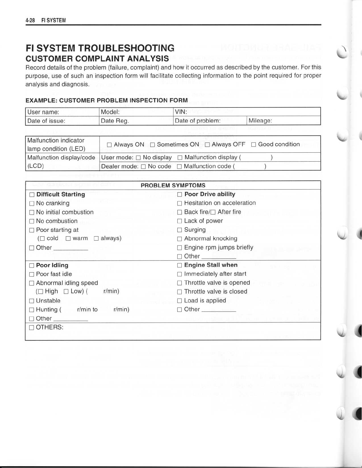
FI SYSTEM TROUBLESHOOTING
CUSTOMER COMPLAINT ANALYSIS
.
Record details of the problem (failure, complaint) and how it occurred as described by the customer
purpose, use of such an inspection form will facilitate collecting information to the point
analysis and diagnosis
.
required for proper
For this
EXAMPLE
User name
Date of issue
Malfunction indicator
lamp condition (LED)
Malfunction display/code
(LCD)
Difficult Starting
∎
0 No cranking
∎ No initial combustion
] No combustion
Poor starting at
]
(I] cold
I] Other
Poor Idling
]
∎ Poor fast idle
∎ Abnormal idling speed
(∎ High
Unstable
]
∎ Hunting
Other
]
OTHERS
]
: CUSTOMER PROBLEM INSPECTION FORM
:
.
∎ warm ∎ always)
Low)
El
(
:
(
r/min to~r/min)
Model
:
Date Reg
•
User mode
Dealer mode
r/min)
.
Always ON ∎ Sometimes ON
No display ∎ Malfunction display
: El
: ∎ No code]Malfunction code
PROBLEM SYMPTOMS
VIN
:
Date of problem
Poor Drive ability
]
∎ Hesitation on acceleration
Back fire/∎ After fire
El
∎ Lack of power
∎ Surging
Abnormal knocking
]
∎ Engine rpm jumps briefly
∎ Other
Engine Stall when
]
∎ Immediately after start
∎ Throttle valve is opened
] Throttle valve is closed
∎ Load is applied
Other
]
:
∎ Always OFF ∎ Good condition
Mileage
(
(
:
)
)
Page 29
~
~
~
~
Fl SYSTEM4-29
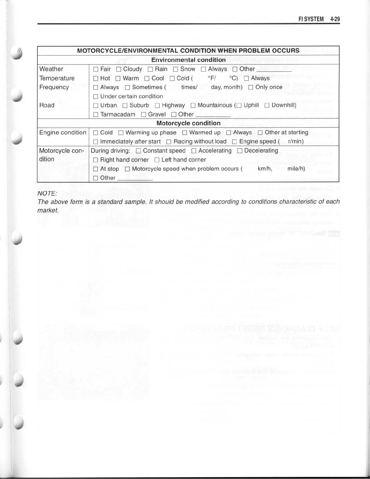
MOTORCYCLE/ENVIRONMENTAL CONDITION WHEN PROBLEM OCCURS
Environmental condition
Weather
Temperature
Frequency
Road
Engine conditionElCold
Motorcycle condition
∎ Fair 0 Cloudy 0 Rain El Snow ∎ Always ∎ Other
0 Hot
∎ Always
∎ Under certain condition
El
El
∎ Immediately after startElRacing without load ∎ Engine speed(r/min)
During driving
∎ Right hand cornerElLeft hand corner
∎ At stop
LI
El Warm El
El
Urban
Tarmacadam
Other
El
Warming up phase ∎ Warmed up ∎ Always
El
El Motorcycle speed when problem occurs (~km/h,
Cool ∎ Cold
Sometimes(
Suburb
: ∎ Constant speed ∎ Accelerating
El Highway El Mountainous (LI Uphill El
Gravel ∎ Other
El
Motorcycle condition
times/
(
°F/~°C)
day, month) ∎ Only once
Always
El
El
Decelerating
El
Downhill)
Other at starting
mile/h)
NOTE
:
The above form is a standard sample
market
.
. It should be modified according to conditions characteristic of each
Page 30

~
~
~
~
~
~
~
~
4-30 FI SYSTEM
SELF-DIAGNOSTIC PROCEDURES
•
Don't disconnect couplers from the ECM, battery cable from
the battery, ECM ground wire harness from the engine or
main fuse before confirming malfunction code (self-diagnostic
trouble code) stored in memory
erase memorized information in ECM memory
•
Malfunction code stored in ECM memory can be checked by
the special tool
•
Before checking malfunction code, read SELF-DIAGNOSIS
FUNCTION "USER MODE and DEALER MODE" (r r4-24,
-25 and -26) carefully to have good understanding as to what
functions are available and how to use it
•
Be sure to read "PRECAUTIONS for Electrical Circuit Service" (r r4-6) before inspection and observe what is written
there
.
•
Remove the seat
•
Connect the special tool to the dealer mode coupler ®A at the
wiring harness, and start the engine or crank the engine for
more than 4 seconds
•
Turn the special tool's switch ON and check the malfunction
code to determine the malfunction part
.
.
.
. Such disconnection will
.
.
.
09930-82720
SELF-DIAGNOSIS RESET PROCEDURE
•
After repairing the trouble, turn OFF the ignition switch and
turn ON again
•
If the malfunction code indicates (COO), the malfunction is
cleared
•
Disconnect the special tool from the dealer mode coupler
.
: Mode select switch
.
.
Page 31

MALFUNCTION CODE AND DEFECTIVE CONDITION
Fl SYSTEM 4-31
40
S
MALFUNCTION
CODE
C00
C11
C12
C13
C14
C15
C21
C22
C23
C24 or C25
DETECTED ITEM
NO FAULT
Camshaft position sen-
sor
Crankshaft position
sensor
Intake air pressure
sensor
Throttle position sensor
Engine coolant tem-
perature sensor
Intake air temperature
sensor
Atmospheric pressure
sensor
Tip over sensor
Ignition signal
The signal does not reach ECM for more than 3 sec
receiving the starter signal
The camshaft position sensor wiring and mechanical parts
(Camshaft position sensor, intake cam pin, wiring/coupler connection)
The signal does not reach ECM for more than 2 sec
receiving the starter signal
The crankshaft position sensor wiring and mechanical parts
(Crankshaft position sensor, wiring/coupler connection)
The sensor should produce following voltage
(0
Without the above range, C13 is indicated
Intake air pressure sensor, wiring/coupler connection
The sensor should produce following voltage
(0
Without the above range, C14 is indicated
Throttle position sensor, wiring/coupler connection
The sensor voltage should be the following
(0
Without the above range, C15 is indicated
Engine coolant temperature sensor, wiring/coupler connection
The sensor voltage should be the following
(0
Without the above range, C21 is indicated
Intake air temperature sensor, wiring/coupler connection
The sensor voltage should be the following
(0
Without the above range, C22 is indicated
Atm
The sensor voltage should be the following for more than 2 sec
after ignition switch turns ON
(0
Without the above value, C23 is indicated
Tip over sensor, wiring/coupler connection
Crankshaft position sensor signal is produced and ECM deter-
mines the ignition signal but signal from ignition coil is interrupted continuous by 4 times or more
C24 or C25 is indicated
Ignition coil, wiring/coupler connection, power supply from the
battery
DETECTED FAILURE CONDITION
CHECK FOR
. after
.
. after
.
.
.50 V < sensor voltage < 4
.20 V <_ sensor voltage < 4
.15 V < sensor voltage < 4
.15 V <_ sensor voltage < 4
.50 V <_ sensor voltage < 4
. pressure sensor, wiring/coupler connection
.20 V < sensor voltage < 4
.85 V)
.
.
.80 V)
.
.
.85 V)
.
.
.85 V)
.
.
.85 V)
.
.
.80 V)
.
. In this case, the code
.
.
Page 32

4-32 FI SYSTEM
C28
C29
C31
C32 or C33
C41
C42
C44
C49
Secondary throttle
valve actuator
No operating voltage is supplied from the ECM, C28 is indi-
cated
STVA lead wire/coupler, STVA
Secondary throttle
valve position sensor
The sensor should produce following voltage
(0
Without the above range, C29 is indicated
Secondary throttle position sensor, wiring/coupler connection
Gear position signal
Gear position signal voltage should be higher than the following
for more than 2 seconds
(Gear position switch voltage > 0
Without the above value, C31 is indicated
Gear position sensor, wiring/coupler connection, gearshift cam,
etc
Fuel injector
Crankshaft position sensor signal is produced and ECM determines the injection signal but fuel injection signal is interrupted
continuous by 4 times or more
C33 is indicated
Injector, wiring/coupler connection, power supply to the injector
Fuel pump relay
No voltage is applied to fuel pump although fuel pump relay is
turned ON, or voltage is applied to fuel pump although fuel
pump relay is turned OFF
Fuel pump relay, connecting lead, power source to fuel pump
relay
Ignition switch
Ignition switch signal is not input in the ECM
Ignition switch, lead wire/coupler
Heated oxygen sensor
(HO2S) [For E-02, 19]
During 02 feedback control, 02 sensor voltage is higher or
lower than the specification
No signal is detected during engine operation or no electrical
power is supplied from the battery
H02S lead wire/coupler connection
Battery voltage supply to the HO2S
PAIR control solenoid
valve (PAIR valve)
When no operating voltage is supplied from the ECM, C49 is
indicated
PAIR valve lead wire/coupler
. STVA can not operate
.10 V 5 sensor voltage < 4
.
.90 V)
.
.
. In this case, the code C32 or
.
.
.
. PAIR valve can not operate
.
.
.6 V)
.
.
.
114
Page 33

~
~
.00
Fl SYSTEM 4-
3 3
"C11" CMP SENSOR CIRCUIT MALFUNCTION
DETECTED CONDITION POSSIBLE CAUSE
The CMP sensor signal does not reach ECM for•Metal particles or foreign materiel being attached
more than 3 seconds after receiving the starter signal
INSPECTION
Step 1
1) Lift and support the fuel tank with its prop stay
2) Turn the ignition switch OFF
3) Check the CMP sensor coupler for loose or poor contacts
If OK, then measure the CMP sensor peak voltage
.
. (=4-65)
on the CMP sensor and rotor tip
•
CMP sensor circuit open or short
•
CMP sensor malfunction
•
ECM malfunction
.
.
+0
4) Insert the needle pointed probes to the CMP sensor coupler
and crank the engine a few seconds or start the engine, and
measure the peak voltage
[
CMP sensor peak voltage
09900-25008
09900-25009
~tzj Tester knob indication : Voltage (_)
Is the peak voltage OK?
YES
NO
: Multi circuit tester
: Needle pointed probe set
Go to step 2
Replace the CMP sensor with a new one, if the
rotor is OK
.
: 3
.7 V and more
Y/W
((
.
.
-OB/W)
Page 34

~
~
~
~
~
~
~
4-34 FI SYSTEM
Step 2
1) Remove the CMP sensor
.
2
2) If the metal particles or foreign material is attached on the
CMP sensor and rotor tip, signal not flow correctly to the
ECM
. Clean the CMP sensor and rotor tip with a spray type
carburetor cleaner and blow dry with compressed air and also
change the engine oil if necessary
.
Is the cleaning OK?
•
Y/W or B/W wire open or shorted to ground, or
YES
NO
poor 12 or 13 connection
If wire and connection are OK, intermittent trou-
•
ble or faulty ECM
•
Recheck each terminal and wire harness for
.
open circuit and poor connection
•
Loose or poor contacts on the CMP sensor coupler or ECM coupler
•
Replace the CMP sensor with a new one
.
(E-
;-4-23)
. (=4-6)
4-6)
Irl
0 0 0 0 0 0 0 0 0 0 0
0000000000000000000000
.
.
1213
0 0
0 0 0 0 0 0 0 0 0
ECM coupler
~\
Page 35

~
~
FI SYSTEM 4-35
do
40
rI
"C12" CKP SENSOR CIRCUIT MALFUNCTION
DETECTED CONDITION
•
No CKP sensor signal for more than 2 seconds after
receiving the starter signal
INSPECTION
Step 1
(r
1) Remove the seat
screw
.
2) Turn the ignition switch OFF
3) Check the CKP sensor coupler for loose or poor contacts
If OK, then measure the CKP sensor resistance
4) Disconnect the CKP sensor coupler and measure the resistance
.
CKP sensor resistance
[
,
5) If OK, then check the continuity between each terminal and
ground
[
.
CKP sensor continuity
r6-3) and left seat tail cover mounting
.
: 130-240 S2
(Blue-Green)
:WQ (Infinity)
(Blue-Ground)
(Green-Ground)
Metal particles or foreign materiel being attached
on the CKP sensor and rotor tip
•
CKP sensor circuit open or short
•
CKP sensor malfunction
•
ECM malfunction
.
.
POSSIBLE CAUSE
(
;round
. .
09900-25008
R J Tester knob indication
Are the resistance and continuity OK?
YES
NO
: Multi circuit tester set
: Resistance (S2)
Go to step 2
Replace the CKP sensor with a new one
.
.
Page 36

~
~
~
~
~
4-36 FI SYSTEM
Step 2
1) Disconnect the CKP sensor coupler
.
2) Crank the engine a few seconds with the starter motor, and
measure the CKP sensor peak voltage at the coupler
CKP sensor peak voltage
: 5
.0 V and more
(0+
Blue -OGreen)
3) Repeat the above test procedure a few times and measure
the highest peak voltage
.
4) If OK, then measure the CKP sensor peak voltage at the ECM
terminals
. .
09900-25008
. (N+/N- or
(SAX)
: Multi circuit tester set
.
0000000000000000000000
000
.000500000000000000
26~30
~
ECM coupler
V
Tester knob indication
: Voltage (---)
Is the peak voltage OK?
•
Green or G/BI wire open or shorted to ground,
or poor 26 or 30 connection
If wire and connection are OK, intermittent trou-
YES
•
ble or faulty ECM
•
Recheck each terminal and wire harness for
open circuit and poor connection
•
Loose or poor contacts on the CKP sensor cou-
NO
pler or ECM coupler
•
Replace the CKP sensor with a new one
.
(L_?--4-23)
.
.
(r
--
74-6)
.
.
Page 37

~
~
FI SYSTEM 4-37
"C13" IAP SENSOR CIRCUIT MALFUNCTION
d
40
40
DETECTED CONDITION
IAP sensor voltage low or high
(0
.50 V < Sensor voltage < 4
(without the above range)
NOTE
:
Note that atmospheric pressure varies depending on
weather conditions as well as altitude
Take that into consideration when inspecting volt-
age
.
INSPECTION
Step 1
1) Lift and support the fuel tank with its prop stay
2) Turn the ignition switch OFF
3) Check the IAP sensor coupler for loose or poor contacts
If OK, then measure the IAP sensor input voltage
.85 V)
.
.
.
([7'4-65)
Clogged vacuum passage between throttle body
•
and IAP sensor
Air being drawn from vacuum passage between
•
throttle body and IAP sensor
IAP sensor circuit open or shorted to ground
•
•
IAP sensor malfunction
ECM malfunction
•
.
.
POSSIBLE CAUSE
4) Disconnect the IAP sensor coupler
5) Turn the ignition switch ON
6) Measure the voltage at the Red wire and ground
7) If OK, then measure the voltage at the Red wire and B/Br
wire
.
IAP sensor input voltage
~ •
09900-25008
(Eli Tester knob indication
Is the voltage OK?
YES
NO
: Multi circuit tester set
Go to Step 2
•
Loose or poor contacts on the ECM coupler
Open or short circuit in the Red wire or B/Br
•
wire
.
.
: Voltage
.
.
: 4.5-5.5 V
(O+
Red -OGround)
(O+
Red -OB/Br)
(-)
.
.
B/Br
Page 38

~
~10~
~
~
~
~
~
~
4- 38FI SYSTEM
Step 2
1) Connect the IAP sensor coupler
2) Insert the needle pointed probes to the lead wire coupler
3) Start the engine at idle speed
.
.
.
4) Measure the IAP sensor output voltage at the wire side coupler (between G/B and B/Br wires)
(
IAP sensor output voltage
.
.
09900-25008
09900-25009
Tester knob indication
: Multi circuit tester set
: Needle pointed probe set
: Voltage
.
: Approx
G/B -OB/Br)
(O
(--)
. 2
.5 V at idle speed
4
YES
NO
Go to Step 3
•
Check the vacuum hose for crack or damage
•
Open or short circuit in the G/B wire
•
Replace the IAP sensor with a new one
.
.
.
.
Step 3
1) Remove the IAP sensor.(1
r4-91)
2) Connect the vacuum pump gauge to the vacuum port of the
IAP sensor
3) Arrange 3 new 1
age is 4
minal and
4) Check the voltage between Vout and ground
.
.5 V batteries in series (check that total volt-
.5
- 5
.0 V) and connectOterminal to the ground ter-
terminal to the Vcc terminal
O+
.
. Also, check if
voltage reduces when vacuum is applied up to 400 mmHg by
using vacuum pump gauge
. .
09917-47010
09900-25008
Tester knob indication
Zi
: Vacuum pump gauge
: Multi circuit tester set
Is the voltage OK?
. (r-
74-39)
: Voltage (--)
6
0000000000000000000000
00000000000
`~
~
16
.0000000000
34
~
1%
1
YES
NO
Red, G/B or B/Br wire open or shorted to
•
ground, or poor 10,16 or 34 connection
(r
-
7-4-23)
If wire and connection are OK, intermittent trou-
•
ble or faulty ECM
•
Recheck each terminal and wire harness for
.
.
open circuit and poor connection . (C r4-6)
If check result is not satisfactory, replace the IAP
sensor with a new one
.
ECM coupler
10
Page 39

Fl SYSTEM 4-39
S
MW
Output voltage (Vcc voltage 4.5-5.0 V, ambient temp
30
°C, 68-86 °F)
ALTITUDE
(Reference)
(ft)
0
2000
2001
1 1
5 000
5 001
8 000
8 001
10 000 3 048
(m)
0
610 707
611
1 524
1 525
1
2 438
2 439
1
ATMOSPHERIC
PRESSURE
(mmHg)
760
707
634
634
567
567
526
kPa
100
1
94
94
85
85
1
76
76
70
. 20
OUTPUT
VOLTAGE
(V)
3
.4-4
3
.0-3
2
.6-3
2
.4-3
-
.0
.7
.4
.1
Page 40

~
~
~
4-
4 0
FI SYSTEM
"C14" TP SENSOR CIRCUIT MALFUNCTION
DETECTED CONDITION
Output voltage low or high
(0
.20 V < Sensor voltage < 4
.80 V)
(without the above range)
•
TP sensor maladjusted
•
TP sensor circuit open or short
•
TP sensor malfunction
•
ECM malfunction
POSSIBLE CAUSE
INSPECTION
Step 1
1) Lift and support the fuel tank with its prop stay
2) Turn the ignition switch OFF
.
3) Check the TP sensor coupler for loose or poor contacts
If OK, then measure the TP sensor input voltage
4) Disconnect the TP sensor coupler
5) Turn the ignition switch ON
.
.
6) Measure the voltage at the Red wire and ground
. (=4-65)
.
.
.
7) If OK, then measure the voltage at the Red wire and B/Br
wire
.
L
TP sensor input voltage
. .
09900-25008
: Multi circuit tester set
: 4.5-5.5 V
Red -OGround)
(O
(O+
Red
-OB/Br)
~g Tester knob indication
: Voltage
Is the voltage OK?
YES
NO
Go to Step 2
•
Loose or poor contacts on the ECM coupler
•
Open or short circuit in the Red wire or B/Br
wire
.
.
(--)
.
Page 41

~
~
~
~
~
~
~
~
FI SYSTEM 4-41
(i
Step 2
1) Turn the ignition switch OFF
2) Disconnect the TP sensor coupler
.
.
3) Check the continuity between P/W wire and ground
L
TP sensor continuity
: -
0 (Infinity)
(P/W - Ground)
4) If OK, then measure the TP sensor resistance at the coupler
.ilk'`~(between P/W and B/Br wires)
.
5) Turn the throttle grip and measure the resistance
[
TP sensor resistance
Throttle valve is closed
Throttle valve is opened
09900-25008
~J
Tester knob indication
: Multi circuit tester set
: Approx
: Approx
: Resistance (S2)
Are the resistance and continuity OK?
YES
NO
Go to Step 3
Reset the TP sensor position correctly
•
•
Replace the TP sensor with a new one
.
.12 kS2
. 1
. 4
.26 kS2
.
.
.
.
or
Step 3
1) Connect the TP sensor coupler
2) Insert the needle pointed probes to the lead wire coupler
3) Turn the ignition switch ON
.
.
.
4) Measure the TP sensor output voltage at the coupler
(between *+ P/W andOB/Br) by turning the throttle grip
.
TP sensor output voltage
Throttle valve is closed
Throttle valve is opened
09900-25008
09900-25009
: Multi circuit tester set
: Needle pointed probe set
.~Tester knob indication
: Approx
: Approx
: Voltage
. 1
. 4
(- -)
.12 V
.26 V
Is the voltage OK?
000000000x00000000
0000000000000000000000
"1'-,
~
YES
• Red, P/W or B/Br wire open or shorted to
ground, or poor 10,19 or 34 connection
4-23)
(=4-23)
•
If wire and connection are OK, intermittent trouble or faulty ECM
•
Recheck each terminal and wire harness for
.
open circuit and poor connection
.
(L'4-6)
.
If check result is not satisfactory, replace the TP
NO
sensor with a new one
.
10
34
ECM coupler
is
.000
Page 42

~
~
~
~
~
4-42
FI SYSTEM
"C15" ECT SENSOR CIRCUIT MALFUNCTION
DETECTED CONDITION
Output voltage low or high
.15 V < Sensor voltage < 4
(0
.85 V)
(without the above range)
ECT sensor circuit open or short
•
ECT sensor malfunction
•
ECM malfunction
•
POSSIBLE CAUSE
INSPECTION
Step 1
1) Turn the ignition switch OFF
2) Check the ECT sensor coupler for loose or poor contacts
.
.
If OK, then measure the ECT sensor voltage at the wire side
coupler
3) Disconnect the coupler and turn the ignition switch ON
4) Measure the voltage between B/BI wire terminal and ground
.
.
.
5) If OK, then measure the voltage between B/BI wire terminal
and B/Br wire terminal
ECT sensor voltage
09900-25008
Tester knob indication
.
: 4 .5
- 5
.5 V
(O+
B/Bl -OGround)
BIB I
(O+
-OBIB r)
: Multi circuit tester set
: Voltage (-)
Is the voltage OK?
YES
NO
Go to Step 2
•
Loose or poor contacts on the ECM coupler
Open or short circuit in the B/BI wire or B/Br
•
wire
.
.
.
Page 43

~
~
~
~
~
.
.d
Step 2
1) Turn the ignition switch OFF
2) Measure the ECT sensor resistance
[
ECT sensor resistance
.
:
Approx
.
. 2
.45 kSZ at 20 °C (68 °F)
(Terminal-Terminal)
09900-25008
~gy Tester knob indication
Refer to page 5-10 for details
: Multi circuit tester set
: Resistance (S2)
.
Is the resistance OK?
•
B/BI or B/Br wire open or shorted to ground, or
YES
poor 34 or 36 connection
If wire and connection are OK, intermittent trou-
•
ble or faulty ECM
•
Recheck each terminal and wire harness for
.
. (F-74-23)
open circuit and poor connection
NO
Replace the ECT sensor with a new one
.(r-7-
4-6)
.
0000000000000000000000
00000000000
~
.0•0000000o
34 36
ECM coupler
~
Fl SYSTEM 4-
4 3
Engine Coolant Temp
20 °C (68 °F)
40 °C (104 °F)
80 °C (176 °F)
100 °C (212 °F)
Resistance
Approx
Approx
Approx
Approx
. 0
. 2
.45 kQ
. 1
.15 kQ
. 0
.318 kS2
.1836 kS2
Page 44

~
~
~
~
~
4-44
FI SYSTEM
"C21" IAT SENSOR CIRCUIT MALFUNCTION
DETECTED CONDITION
Output voltage low or high
(0
.15 V <_ Sensor voltage < 4
(without the above range)
INSPECTION
Step 1
1) Lift and support the fuel tank with its prop stay
2) Turn the ignition switch OFF
3) Check the IAT sensor coupler for loose or poor contacts
If OK, then measure the IAT sensor voltage at the wire side
coupler
4) Disconnect the coupler and turn the ignition switch ON
5) Measure the voltage between Dg wire terminal and ground
6) If OK, then measure the voltage between Dg wire terminal
and B/Br wire terminal
.
IAT sensor voltage
.85 V)
.
.
: 4.5- 5
(O
(~+
.5 V
Dg -OGround)
Dg -0B/Br)
.
(r
•
IAT sensor circuit open or short
•
IAT sensor malfunction
•
ECM malfunction
--
74-65)
.
.
.
POSSIBLE CAUSE
09900-25008
Tester knob indication
~J
Is the voltage OK?
YES
NO
: Multi circuit tester set
Go to Step 2
Loose or poor contacts on the ECM coupler
•
•
Open or short circuit in the Dg wire or B/Br wire
: Voltage (--)
.
.
.
Page 45

~
~
~
FI SYSTEM 4-45
Step 2
1) Turn the ignition switch OFF
2) Measure the IAT sensor resistance
.
.
IAT sensor resistance
. .
09900-25008
: Multi circuit tester set
Tester knob indication
Is the resistance OK?
•
Dg or B/Br wire open or shorted to ground, or
poor 14 or 34 connection
If wire and connection are OK, intermittent trou-
YES
•
ble or faulty ECM
•
Recheck each terminal and wire harness for
open circuit and poor connection
NO
Replace the IAT sensor with a new one
Intake Air Temp
20 °C (68 °F)
40 °C (104 °F)
80 °C (176 °F)
100 °C (212 °F)
: Approx
(Terminal -
. 2
.45 kL2 at 20 °C (68 °F)
Terminal)
: Resistance (S2)
. (=4-23)
.
. (C r4-6)
Resistance
Approx
Approx
Approx
Approx
. 2
. 1
. 0
.322 kQ
. 0
.189 kQ2
.
.45 kQ
.14 kS2
0 0 0 0 0 0 0 0 0 0 0 0 0 0 0 0 0 0 0 0 0 0
0000000000050000000000
ECM coupler
14
34
:
NOTE
IAT sensor resistance measurement method is the same way as
that of the ECT sensor
. Refer to page 5-10 for details
.
Page 46

~
~
4
.46 FI SYSTEM
"C22" AP SENSOR CIRCUIT MALFUNCTION
DETECTED CONDITION
AP sensor voltage low or high
(0
.50 V < Sensor voltage < 4
(without the above range)
NOTE
:
Note that atmospheric pressure varies depending on
weather conditions as well as altitude
Take that into consideration when inspecting volt-
age
.
INSPECTION
Step 1
1) Remove the seat.([7'6-7)
2) Turn the ignition switch OFF
3) Check the AP sensor coupler for loose or poor contacts
If OK, then measure the AP sensor input voltage
4) Disconnect the AP sensor coupler
5) Turn the ignition switch ON
6) Measure the voltage at the Red wire and ground
7) If OK, then measure the voltage at the Red wire and B/Br
wire
.
.85 V)
.
.
.
.
•
Clogged air passage with dust
•
AP sensor circuit open or shorted to ground
•
AP sensor malfunction
•
ECM malfunction
.
.
.
POSSIBLE CAUSE
IN
('~,~AP sensor input voltage
: 4 .5
(O
(O+
09900-25008
Tester knob indication
Is the voltage OK?
YES
NO
: Multi circuit tester set
: Voltage (---)
Go to Step 2
•
Loose or poor contacts on the ECM coupler
•
Open or short circuit in the Red wire or B/Br
wire
.
.
- 5
.5 V
Red
-OGround)
Red
-OB/Br)
1
.
B/Br
Page 47

~
~
~
~
~
~
~
~
~
FI SYSTEM 4-47
~(
Step 2
1) Connect the AP sensor coupler
2) Insert the needle pointed probes to the lead wire coupler
Turn the ignition switch ON
.
.
.
3) Measure the AP sensor output voltage at the wire side coupler (between G/Y and B/Br wires)
(
AP sensor output voltage
Approx
(E
G/Y
09900-25008
09900-25009
)g Tester knob indication
YES
NO
: Multi circuit tester set
: Needle pointed probe set
: Voltage
Go to Step 3
•
Check the air passage for clogging
Open or short circuit in the G/Y wire
•
•
Replace the AP sensor with a new one
.
.
:
. 4
.0 V (760 mmHg, 100 kPa)
-OB/Br)
(--)
.
.
.
Step 3
1) Remove the AP sensor
.
2) Connect the vacuum pump gauge to the air passage port of
the AP sensor
3) Arrange 3 new 1
age is 4.5- 5
minal andO+terminal to the Vcc terminal
4) Check the voltage between Vout and ground
.
.5 V batteries in series (check that total volt-
.0 V) and connectOterminal to the ground ter-
.
. Also, check if
voltage reduces when vacuum is applied up to 400 mmHg by
using vacuum pump gauge
. .
09917-47010
09900-25008
: Vacuum pump gauge
: Multi circuit tester set
. (=4-48)
rvli
Tester knob indication
itv
~
Is the voltage OK?
•
Red, G/Y or B/Br wire open or shorted to
ground, or poor 10,17 or 34 connection
: Voltage
(-)
000000000
000000000 0*0000 00000
.
10
.000000500000
34
ECM coupler
17
~
(C r4-23)
YES
If wire and connection are OK, intermittent trou-
•
ble or faulty ECM
•
Recheck each terminal and wire harness for
open circuit and poor connection
.
. (E7'4-6)
If check result is not satisfactory, replace the AP
NO
sensor with a new one
.
Page 48

FI
4-48
Output voltage (Vcc voltage 4
30 °C, 68-86 °F)
SYSTEM
.5-5
.0 V, ambient temp
. 20
-
ALTITUDE
(Reference)
(ft)
0 0
2000
2001
5 000
5 001
1
8 000
8 001
10 000
(m)
610
611
1
1 524
1 525
2 438
2 439
1
3 048
ATMOSPHERIC
PRESSURE
(mmHg)
760 100
707
707
1
634
634
567
567
526
kPa
94
94
85
85
76
76
70
OUTPUT
VOLTAGE
(V)
3
.4-4
3
.0-3
2
.6-3
.4-3
2
.0
.7
.4
.1
Page 49

~
~
~
~
FI SYSTEM 4-49
(r
"C23" TO SENSOR CIRCUIT MALFUNCTION
DETECTED CONDITION
Output voltage low or high
(0
.20 V < Sensor voltage < 4
(without the above range)
INSPECTION
Step 1
1) Remove the frame cover
2) Turn the ignition switch OFF
3) Check the TO sensor coupler for loose or poor contacts
If OK, then measure the TO sensor resistance
4) Disconnect the TO sensor coupler
5) Measure the resistance between Red wire and B/Br wire terminals
[
~p Tester knob indication
.
TO sensor resistance
09900-25008
Is the resistance OK?
: Multi circuit tester set
.80 V)
. (Clr6-7)
.
.
.1 -19
: 19
(Red -
: Resistance (S2)
.7 kS2
B/Br)
.
TO sensor circuit open or short
•
TO sensor malfunction
•
•
ECM malfunction
.
POSSIBLE CAUSE
1
YES
NO
Go to Step 2
Replace the TO sensor with a new one
.
.
S
Page 50

~
~
~
~
~
~
~
~
4-50 FI SYSTEM
Step 2
1) Connect the TO sensor coupler
2) Insert the needle pointed probes to the lead wire coupler
3) Turn the ignition switch ON
.
.
.
4) Measure the voltage at the wire side coupler between Br/W
and B/Br wires
•
TO sensor voltage
.
: 1
.4 V and less
(E
Br/W
-OB/Br)
Also, measure the voltage when leaning of the motorcycle
.
5) Dismount the TO sensor from its bracket and measure the
voltage when it is leaned more than 65°, left and right, from
the horizontal level
•
TO sensor voltage
09900-25008
09900-25009
~P
Tester knob indication
.
: 3
.7 V and more
Br/W
(0+
-OB/Br)
: Multi circuit tester set
: Needle pointed probe set
: Voltage
(---)
Is the voltage OK?
•
Red, Br/W or B/Br wire open or shorted to
YES
NO
ground, or poor
((74-23)
•
If wire and connection are OK, intermittent trouble or faulty ECM
•
Recheck each terminal and wire harness for
open circuit and poor connection
•
Loose or poor contacts on the ECM coupler
Open or short circuit in the Br/W wire or B/Br
•
wire
.
•
Replace the TO sensor with a new one
(2,
34 or 41 connection
.
.
(r
-7-
.
0000000000000000000000
00000000000
4-6)
.
.
000005000
•0
34
~
ECM coupler
41
~
Page 51

~
~
~
~
~
FI SYSTEM 4-51
1r
"C24" or "C25" IGINTION SYSTEM MALFUNCTION
*Refer to the IGNITION SYSTEM for details
.
(E"
77-22)
"C28" STV ACTUATOR CIRCUIT MALFUNCTION
DETECTED CONDITION
The operation voltage does not reach the STVA
ECM does not receive communication signal from
the STVA or STVA dose not operate the ECM signal
INSPECTION
Step 1
1) Lift and support the fuel tank with its prop stay
2) Turn the ignition switch OFF
3) Remove the air cleaner element
4) Check the STVA lead wire coupler for loose or poor contacts
5) Turn the ignition switch ON to check the STV operation
STV operating order
any position (Battery voltage > 8
Is the operating order OK?
:
100% open-any position
.0 V)
.
. (E'2-5)
.
.
(C---r4-65)
STVA malfunction
•
•
STVA circuit open or short
.
•
STVA motor malfunction
.
.
POSSIBLE CAUSE
YES
NO
Go to Step 2
Loose or poor contacts on the STVA coupler
•
Open or short circuit in the R/B wire and B/R
•
wires
.
.
.
Page 52

~
~
~
4-52 FI SYSTEM
Step 2
1) Turn the ignition switch OFF
2) Remove the air cleaner box
3) Check the STVA lead wire coupler for loose or poor contacts
4) Disconnect the STVA lead wire coupler
5) Check the continuity between R/B wire and ground
41
STVA continuity
:ooSZ (Infinity)
.
. ((74-75)
.
.
.
6) If OK, then measure the STVA resistance (between R/B wire
and B/R wires)
.
STVA resistance
: 7-14 Q
(R/B-B/R)
09900-25008
Tester knob indication
: Multi circuit tester set
: Resistance
(S2)
Are the resistance and continuity OK?
•
Loose or poor contacts on the STVA coupler, or
YES
NO
poor 20 or(aconnection
•
If wire and connection are OK, intermittent trouble or faulty ECM
•
Recheck each terminal and wire harness for
.
open circuit and poor connection
4-6)
(=4-6)
Replace the STVA with a new one
. (c'4-23)
.
.
0000000000000000000
0000000000000000000000
ECM coupler
20 22
.0
•
~~
J
Page 53

~
~
~
FI SYSTEM 4-53
"C29" STP SENSOR CIRCUIT MALFUNCTION
40
DETECTED CONDITION
Output voltage low or high
(0
.10 V < Sensor voltage < 4
(without the above range)
INSPECTION
Step 1
1) Lift and support the fuel tank with its prop stay
2) Turn the ignition switch OFF
3) Check the STP sensor coupler for loose or poor contacts
4) Disconnect the STP sensor coupler
5) Turn the ignition switch ON
6) Measure the voltage at the Red wire and ground
7) If OK, then measure the voltage at the Red wire and B/Br
wire
.
[
STP sensor input voltage
.
.
09900-25008
: Multi circuit tester set
.90 V)
.
.
.
: 4 .5-5
(( Red -OGround)
(O+
.5 V
Red -OB/Br)
•
STP sensor maladjusted
•
STP sensor circuit open or short
•
STP sensor malfunction
•
ECM malfunction
. (=4-65)
4-65)
.
.
POSSIBLE CAUSE
1
,'p Tester knob indication
Is the voltage OK?
YES
NO
Go to Step 2
•
Loose or poor contacts on the ECM coupler
•
Open or short circuit in the Red wire and B/Br
wires
.
: Voltage
.
(--)
.
Page 54

~
~
4-54 FI SYSTEM
Step 2
1) Turn the ignition switch OFF
2) Remove the air cleaner box (C'4-75) and disconnect the
STP sensor coupler
3) To set the ST valve to fully close position, turn the STVA
motor shaftOcounterclockwise by fingers
.
.
.
4) Measure the position sensor resistance at fully close position
STP sensor resistance
ST valve is fully closed
5) Then, to set the ST valve to fully open position, turn the STVA
motor shaft 02 clockwise by fingers
6) Measure the position sensor resistance at fully open position
: Approx
(Yellow-Black)
.
. 0
.58 kS2
.
.
[
STP sensor resistance
ST valve is fully opened
09900-25008
$
Tester knob indication : Resistance
CAUTION
Do not use the tool for turning the STVA shaft to pre-
vent breakdown
Is the resistance OK?
YES
NO
: Multi circuit tester set
.
Go to Step 3
Reset the STP sensor position correctly
'
•
Replace the STP sensor with a new one
.
: Approx
(Yellow - Black)
. 4
.38 kS2
(S2)
.
.
04,
Page 55

~
~
40
~/
Step 3
1) Turn the ignition switch OFF and connect the STP sensor
coupler
.
2) Insert the needle pointed probes into the back side of the
position sensor lead wire coupler
3) Disconnect the
STVA
motor/injector coupler 1O
4) To set the ST valve to fully close position, turn the
motor shaftO2counterclockwise by fingers
5) Turn the ignition switch ON
.
.
STVA
.
.
6) Measure the position sensor output voltage at fully close posi-
tion
.
STP sensor output voltage
ST valve is fully closed
Approx
(O+
. 0
Yellow
:
.58 V at input voltage is 5
.0 V
-OBlack)
FI SYSTEM 4-
5 5
40
7) Then, to set the ST valve to fully open position, turn the
motor shaft02clockwise by fingers
.
STVA
8) Measure the position sensor output voltage at fully open position
.
STP sensor output voltage
ST valve is fully opened
Approx
Yellow
(O
09900-25008
09900-25009
: Multi circuit tester set
: Needle pointed probe set
(„$Tester knob indication
:
. 4
.38 V at input voltage is 5
-OBlack)
: Voltage (--)
.0 V
Page 56

~
~
4-56 FI SYSTEM
Is the voltage OK?
•
Red, Yellow or B/Br wire open or shorted to
ground, or poor 10
(=4-23)
~
YES
NO
If
the
wire
or
faulty
and
•
trouble
•
Recheck each terminal and wire harness for
open circuit and poor connection
(=4-6)
If check result is not satisfactory, replace the
sensor with a new one
,
34 or ® connection .
000000000000000000000
000000000000000000000
connection
ECM
are
OK,
intermittent
.
.
STP
.
10
34
~
ECM coupler
•
44
Page 57

~
~
~
~
~
~
~
~
FI SYSTEM 4-57
mr
i'
"C31" GEAR POSITION (GP) SWITCH CIRCUIT MALFUNCTION
DETECTED CONDITION
No Gear Position switch voltage
Switch voltage low
(Switch voltage > 0
.6 V)
•
Gear Position switch circuit open or short
•
Gear Position switch malfunction
•
ECM malfunction
(without the above range)
INSPECTION
1) Lift and support the fuel tank with its prop stay
2) Turn the ignition switch OFF
.
3) Check the GP switch coupler for loose or poor contacts
If OK, then measure the GP switch voltage
4) Support the motorcycle with a jack
5) Turn the side-stand to up-right position
6) Turn the engine stop switch ON
.
.
.
7) Insert the needle pointed probe to the lead wire coupler
8) Turn the ignition switch ON
.
. (
r
-
74-65)
.
.
.
9) Measure the voltage between Pink wire and ground, when
shifting the gearshift lever from 1st to top
GP switch voltage
:
.
09900-25008
09900-25009
: Multi circuit tester set
: Needle pointed probe set
: 0
.6 V and more
(O+
Pink -OGround)
.
POSSIBLE CAUSE
Tester knob indication
Is the voltage OK?
•
Pink wire open or shorted to ground, or poor 31
YES
connection
If wire and connection are OK, intermittent trou-
•
. (f"74-23)
ble or fautrly ECM
Recheck each terminal and wire harness for
open circuit and poor connection
Open or short circuit in the Pink wire
NO
•
•
Replace the GP switch with a new one
: Voltage
.
( j
.
(L--7-4-6)
.
.
i
0000000000000000000000
0000000050000000000000
31
ECM coupler
/~
Page 58

~
~
~
~
4-58
Fl SYSTEM
"C32" or "C33" FUEL INJECTOR CIRCUIT MALFUNCTION
DETECTED CONDITION
CKP signals produced and ECM determines the
injection signal but fuel injection signal is interrupted
continuous by 4 times or more
INSPECTION
Step 1
1) Lift and support the fuel tank with its prop stay
2) Turn the ignition switch OFF
3) Remove the air cleaner box
4) Check the injector coupler for loose or poor contacts
If OK, then measure the injector resistance
5) Disconnect the injector coupler and measure the resistance
between terminals
Injector resistance
.
.
.
. (=4-75)
.
: 11 -
13 0 at 20 °C (68 °F)
(Terminal-Terminal)
•
Injector circuit open or short
•
Injector malfunction
•
ECM malfunction
. (Cr4-65)
.
POSSIBLE CAUSE
6) If OK, then check the continuity between each terminal and
ground
[
0
.
Injector continuity
09900-25008
Tester knob indication
Is the resistance OK?
YES
NO
: Multi circuit tester set
Go to Step 2
Replace the injector with a new one
74-78 and -83)
(F
-
: o
(Terminal-Ground)
.
92 (Infinity)
: Resistance (S2)
.
Page 59

~
~
~
~
~
FI SYSTEM 4-59
~f
Step 2
1) Turn the ignition switch ON
.
2) Measure the injector voltage between Y/R wire and ground
Injector voltage
NOTE
:
: Battery voltage
(~+
Y/R
- O
Ground)
L
.
Injector voltage can be detected only 3 seconds after ignition
switch is turned ON
. .
09900-25008
~P
Tester knob indication
.
: Multi circuit tester set
: Voltage
(_ )
Is the voltage OK?
• Gr/W, Gr/B or Y/R wire open or shorted to
ground, or poor 05,© or 28 connection
.
r
~~
56
0000000000000000000000
0000010000000000000000
~
(f"'4-23)
YES
NO
•
If wire and connection are OK, intermittent trou-
ble or faulty ECM
•
Recheck each terminal and wire harness for
open circuit and poor connection
.
. (Lc4-6)
Open circuit in the Y/R wire or FP relay circuit mal-
function
.
28
~
ECM coupler
J
I
Page 60

~
~
~
~
~
~
~
~
~
~
~
4-60
FI SYSTEM
"C41" FP RELAY CIRCUIT MALFUNCTION
DETECTED CONDITION
No voltage is applied to fuel pump although fuel
pump relay is turned ON, or voltage is applied to fuel
pump although fuel pump relay is turned OFF
.
•
Fuel pump relay circuit open or short
•
Fuel pump relay malfunction
•
ECM malfunction
INSPECTION
Step 1
1) Remove the seat
2) Turn the ignition switch OFF
3) Check the FP relay coupler for loose or poor contacts
. (=6-7)
6-7)
.
.
If OK, then check the insulation and continuity . Refer to page
4-68 for details
.
Is the FP relay OK?
•
Y/B or Y/R wire open or shorted to ground, or
YES
NO
poor 28 or 3~ connection
If wire and connection are OK, intermittent trou-
•
ble or faulty ECM
•
Recheck each terminal and wire harness for
.
open circuit and poor connection
Replace the FP relay with a new one
. (=4-23)
.
(["r4-6)
.
POSSIBLE CAUSE
0000000000000000000000
00000
•0
00
.000000000000
28~32
ECM coupler
"C42" IG SWITCH CIRCUIT MALFUNCTION
DETECTED CONDITION
Ignition switch signal is not input in the ECM
INSPECTION
*Refer to the IGNITION SWITCH INSPECTION for details
•
Lift and support the fuel tank with its prop stay
•
Remove the air cleaner box
•
Inspect the ignition switch
.
(1'"74-75)
.
( r -
7-7-35)
.
.(rr4-65)
•
Ignition system circuit open or short
•
ECM malfunction
.
In
POSSIBLE CAUSE
Page 61

~
~
~
FI SYSTEM 4-61
"C44" H02 SENSOR (HO2S) CIRCUIT MALFUNCTION (FOR E-02,19)
DETECTED CONDITION POSSIBLE CAUSE
40
During 02 feedback control, 02 sensor voltage is
higher or lower than the specification
The heater circuit disconnection is detected during
engine operation, or no electrical power is supplied
from battery
INSPECTION
Step
1
1) Lift and support the fuel tank with its prop stay
2) Turn the ignition switch OFF
3) Check the H02 sensor coupler for loose or poor contacts
4) Insert the needle pointed probes to the H02 sensor lead wire
coupler
5) Warm up the engine enough
6) Measure the H02 sensor output voltage at the coupler
(between W/G or B and B/Br or Gr wires) when idling condition
.
7) Measure the H02 sensor output voltage while holding the
engine speed at 3 000 r/min
.
.
.
.
.
.
. (
r
•
H02 sensor or its circuit open or short
•
Fuel system malfunction
•
ECM malfunction
-
74-65)
.
H02 sensor output voltage at idle speed
0
.4 V and less
H02 sensor output voltage at 3 000 r/min
0
.6 V and more
09900-25008
09900-25009
Tester knob indication
Is the voltage OK?
YES
NO
: Multi circuit tester set
: Needle pointed probe set
Go to Step 2
Replace the HOB
.
(E
W/G or B-O
(OO
W/G or B
: Voltage
(- -)
:
-OB/Br or Gr)
B/Br or Gr)
:
Page 62

~
~
~
~
~
~
~
~
~34~
4-62 FI SYSTEM
Step 2
1) Turn the ignition switch OFF
.
2) Turn the ignition switch ON and measure the heater voltage
between O/W wire (ECM side) and ground
.
3) If the tester voltage indicates the battery voltage for few seconds, it is good condition
•
Heater voltage
NOTE
:
.
: Battery voltage
01W
(
-
O
Ground)
Battery voltage can be detected only during few seconds after
ignition switch is turned ON
.
09900-25008
Tester knob indication
: Multi circuit tester set
: Voltage (-)
Is the voltage OK?
YES
NO
Step 3
1) Turn the ignition switch OFF
2) Disconnect the H02 sensor coupler
3) Check the resistance between the terminals (White
of the H02 sensor
•
H02 heater resistance
NOTE
•
Temperature of the sensor affects resistance value largely-
•
Make sure that the sensor heater is at correct temperature
. .
09900-25008
Tester knob indication
0
Go to Step 3
Replace the H02 sensor with a new one
.
.
3
.
.
-
White)
.
-
5 Q (at 23 °C/73
: 4
(White
- White)
.4 °F)
:
.
: Multi circuit tester set
: Resistance (Q)
Is the resistance OK?
YES
NO
•
W/G, W/B, O/G or B/Br wire open or shorted to
ground, or poor
(r
r4-23)
•
If wire and connection are OK, intermittent trouble or faulty ECM
•
Recheck each terminal and wire harness for
®, 015),
.
24
or
connection
C4)
.
open circuit and poor connection . (f"74-6)
Replace the HO2 sensor with a new one
.
II
0000000S000000~0000000
000000ooooo
24
8
ECM coupler
15
•0
000000000
-
Page 63

"C49" PAIR CONTROL SOLENOID VALVE
Fl SYSTEM 4-
6 3
40
1
40
DETECTED CONDITION
No signal from PAIR valve after starting the engine
•
PAIR valve circuit open or short
•
PAIR valve malfunction
•
ECM malfunction
POSSIBLE CAUSE
INSPECTION
Step 1
1) Lift and support the fuel tank with its prop stay
2) Turn the ignition switch OFF
.
3) Check the PAIR valve coupler for loose or poor contacts
If OK, then measure the PAIR valve resistance
4) Disconnect the PAIR valve coupler
.
.
(r-_
.
74-65)
.
5) Measure the resistance between Red and Black wire terminals
.
PAIR valve resistance
: 20-24 S2 (at 20 °C/68 °F)
(Red - Black)
. .
09900-25008
~gy Tester knob indication
: Multi circuit tester set
: Resistance (S2)
Is the resistance OK?
40
40
aI
YES
NO
Go to Step 2
Replace the PAIR valve with a new one
.
.
Page 64

~
~
~
~
~
~
~
4-64 FI SYSTEM
Step 2
1) Disconnect the PAIR valve coupler
2) Turn the ignition switch ON
.
3) Measure the voltage between O/W and Brown wire terminals
.
.
PAIR valve voltage
.
.
09900-25008
: Multi circuit tester set
~gy Tester knob indication
: Battery voltage
O/W
(O
: Voltage
Is the voltage OK?
Brown or O/G wire open or shorted to ground,
•
or poor7or 15 connection
If wire and connection are OK, intermittent trou-
YES
•
ble or faulty ECM
•
Recheck each terminal and wire harness for
open circuit and poor connection
•
Loose or poor contacts on the ECM coupler
NO
•
Open or short circuit
•
Replace the PAIR valve with a new one
-OGround)
(-)
.
.
. (CY4-23)
.
(r -
74-6)
000000
0000000000000000000000
7
•0
00000050000000
ECM coupler
15
.
.
Page 65

~
~
~
~
~
~
~
l
FUEL SYSTEM
FUEL TANK LIFT-UP
•
Remove the seat
•
Remove the fuel tank mounting bolts
•
Lift and support the fuel tank with its prop stay
. (L7'6-7)
.
.
FI SYSTEM
4-65
FUEL TANK REMOVAL
•
Lift and support the fuel tank with its prop stay
•
Disconnect the fuel pump lead wire coupler
•
Place a rag under the fuel feed hose and disconnect the feed
hoseOZfrom the fuel tank
CAUTION
When removing the fuel tank, do not leave the fuel
feed hose
A WARNING
Gasoline is highly flammable and explosive
Keep heat, spark and flame away
•
Remove the air vent hose and fuel drain hose
on the fuel tank side
OO
.
.
.
. (=above)
D
.
.
.
Page 66

~
~
~
~
~
FI SYSTEM
4-66
•
Remove the fuel tank mounting bolt
•
Remove the fuel tank
•
Remove the fuel tank bracket
.
.
.
•
Remove the fuel tank stay and its rubber cushion
FUEL TANK INSTALLATION
•
Installation is in the reverse order of removal
.
.
Page 67

~
~
~
~
~
~
~
~
~
~
~
FUEL PRESSURE INSPECTION
•
Lift and support the fuel tank with the fuel tank prop stay
(
r--
i-4-65)
•
Place a rag under the fuel feed hose
•
Disconnect the fuel feed hose from the fuel delivery pipe
•
Install the special tools between the fuel tank and fuel delivery
pipe
.
09940-40211
09940-40220
09915-77331
09915-74521
Turn the ignition switch ON and check the fuel pressure
Fuel pressure : Approx
If the fuel pressure is lower than the specification, inspect the
following items
•
Fuel hose leakage
•
Clogged fuel filter
•
Pressure regulator
•
Fuel pump
: Fuel pressure gauge adaptor
: Fuel pressure gauge hose attachment
: Oil pressure gauge
: Oil pressure gauge hose
. 300 kPa (3
:
.
.
.0 kg f/cm2, 43 psi)
.
.
FI SYSTEM 4-
6
7
If the fuel pressure is higher than the specification, inspect the
following items
•
Fuel pump check valve
•
Pressure regulator
A
WARNING
•
Before removing the special tools, turn the ignition
switch to OFF position and release the fuel pressure
slowly
•
Gasoline is highly flammable and explosive . Keep
heat, sparks and flame away
:
.
.
Page 68

~
~
~
~
~
~~
~~
4-68 FI SYSTEM
FUEL PUMP INSPECTION
Turn the ignition switch ON and check that the fuel pump operates for few seconds
If the fuel pump motor does not make operating sound, replace
the fuel pump assembly or inspect the fuel pump relay and tip
over sensor
FUEL DISCHARGE AMOUNT INSPECTION
A
WARNING
.
.
Gasoline is highly flammable and explosive
Keep heat, spark and flame away
•
Lift and support the fuel tank with the fuel tank prop stay
(C
r4-65)
•
Disconnect the fuel feed hose from the fuel delivery pipe
•
Place the measuring cylinder and insert the fuel feed hose
end into the measuring cylinder
•
Disconnect the ECM lead wire coupler
•
Push the lock
low with red tracer)
•
Apply 12 volts to the fuel pump for 10 seconds and measure
the amount of fuel discharged
Battery(Oterminal
OO
to pull out the power source lead wire (Yel-
.
Power source lead wire 90
(Yellow with red tracer)
.
.
.
.
.
.
.
If the pump does not discharge the amount specified, it means
that the fuel pump is defective or that the fuel filter is clogged
Fuel discharge amount
NOTE
:
The battery must be in fully charged condition
: 168 ml and more/10 sec
(5
.7/5
.9 US/Imp oz)/10 sec
.
.
.
.
Page 69

~
~
~
~
~
~
.0
FUEL PUMP RELAY INSPECTION
Fuel pump relay is located behind the ECM
•
Remove the seat
•
Remove the fuel pump relay
.
.
First, check the insulation between 1O and
pocket tester
andOto ®, and check the continuity between
03
. Then apply 12 volts toO3and ® terminals,O+to
If there is no continuity, replace it with a new one
.
terminals with
O
and 02
0
.
.
FI SYSTEM 4-
6 9
Id
FUEL PUMP AND FUEL FILTER REMOVAL
•
Remove the fuel tank.(f
•
Remove the heat shield
•
Remove the fuel pump assembly by removing its mounting
bolts diagonally
.
r4-65)
.
A WARNING
Gasoline is highly flammable and explosive
Keep heat, spark and flame away
•
Remove the nuts
.
.
.
Page 70

~
~
~
~
~
4-70 FI SYSTEM
•
Remove the screws and fuel level thermistor
•
Remove the fuel pump assembly from the fuel pump plate
.
.
•
Remove the fuel pump holder
•
Remove the rubber cap
•
Remove the fuel mesh filter
.
.
.
Page 71

~
~
~
~
~
~
Fl SYSTEM 4-71
((
•
Remove the fuel pressure regulator holder
pressure regulator
•
Remove the fuel pump
Z
.
.
O
and the fuel
FUEL MESH FILTER INSPECTION AND
CLEANING
If the fuel mesh filter is clogged with sediment or rust, fuel will
not flow smoothly and loss in engine power may result
•
Blow the fuel mesh filter with compressed air
NOTE
:
If the fuel mesh filter is clogged with many sediment or rust,
replace the fuel filter cartridge with a new one
.
.
.
O
too
FUEL PUMP CASE BUSHING INSPECTION
•
Inspect the fuel pump case rubber bushing for damage
THERMISTOR INSPECTION
(1
--
7-7-29)
.
FUEL PUMP AND FUEL MESH FILTER
INSTALLATION
Install the fuel pump and fuel mesh filter in the reverse order of
removal, and pay attention to the following points
•
Install the new 0-rings to the fuel pressure regulator and fuel
pipe
.
•
Apply thin coat of the engine oil to the 0-rings
:
.
Page 72

~
~
~
~
4-72FlSYSTEM
CAUTION
Use the new 0-rings to prevent fuel leakage
•
Tighten the screws together with the lead wire terminals and
fuel level thermistor
•
Tighten the nuts together with the lead wire terminals
...
. . .
•
•
(+ terminal for fuel pump
. . ... .
Thermistor for fuel level
.
.
.
Im
:
+O
OA
terminal for fuel pump
©
: Thermistor for fuel level
: Ground terminal
©
SI
IMMM
Page 73

~
~
~
FI SYSTEM 4-73
•
Install the new 0-ring and apply grease to it
.
A WARNING
The O-ring must be replaced with a new one to prevent
fuel leakage
99000-25030
99000-25010
•
When installing the fuel pump assembly, first tighten all the
.
: SUZUKI SUPER GREASE "A" (USA)
: SUZUKI SUPER GREASE "A"
(Others)
fuel pump assembly mounting bolts lightly in the ascending
order of numbers, and then tighten them to the specified
torque in the above tightening order
Fuel pump mounting bolt
NOTE
:
: 10 N
.m (1
.0 kgf-m,
7
.3
lb-ft)
Apply a small quantity of the THREAD LOCK to the thread por-
tion of the fuel pump mounting bolt
99000-32050
: THREAD LOCK "1342"
.
Fuel pressure regulator
(2 Fuel pump case/Fuel filter cartridge
(For high pressure)
Fuel pump
•
•
Fuel mesh filter
(For low pressure)
•
Fuel level thermistor
W
,~~
E~
MEN
.
.~
l
Page 74

~
4
-74
FI SYSTEM
THROTTLE BODY AND STV ACTUATOR
CONSTRUCTION
D
TP sensor
2© STP sensor
03 STV actuator
® Fuel delivery pipe
~5 0-ring
© Injector
07 Cushion seal
5 N
•m
.5 kgf-m, 3
(0
.7 Ib-ft)
05 -
ff
5
H
0
1 :J
~~ 2 N
/~ 2 N
.2 kgf-m, 1
(0
•m
.2 kgf-m, 1
(0
•m
.5 Ib-ft)
.5 lb-ft)
Vr
Page 75

Page 76

~
~
~
~
~
~
~
~
~
4-
7 6
FI SYSTEM
•
Disconnect the PAIR hose
•
Remove the PAIR valve
•
Remove the air cleaner box
THROTTLE BODY
•
Lift and support the fuel tank with its prop stay
•
Remove the air cleaner box
•
Disconnect the fuel feed hose
•
Disconnect the TP, STP and STVA motor/injector coupler
.
.
.
. (=4-75)
.
. (L14-65)
4-75)
.
•
Disconnect the IAP sensor vacuum hose
•
Disconnect the idle stop screw
.
.
Page 77

~
~
~
~
FI SYSTEM4-7 7
•
Loosen the throttle body clamp screws
.
r+
•
Disconnect the throttle cables from their drum
•
Dismount the throttle body assembly
CAUTION
•
Be careful not to damage the throttle cable bracket
and fast idle lever when dismounting or remounting
the throttle body assembly
•
After disconnecting the throttle cables, do not snap
the throttle valve from full open to full close
cause damage to the throttle valve and throttle body
THROTTLE BODY DISASSEMBLY
•
Remove the IAP sensor vacuum hose
,
.
.
.
. It may
.
.
Page 78

~
~
~
~
~
4-
7 8
Fl SYSTEM
•
Disconnect the STVA motor and injector couplers
.
CAUTION
* Do not attempt to remove or disassemble the STVA
motor
.
* The STVA motor is available only as a throttle body
assembly
Remove the throttle link rod 90 and secondary throttle link rod
•
OO
.
NOTE
:
.
The throttle link rod 1O is longer than the secondary throttle link
rod (O
.
•
Remove the fuel delivery pipe
•
Remove the fuel injectors
•
Remove the TPS and STPS with the special tool
.
.
.
09930-11950
09930-11960
: Torx wrench
: Torx wrench
Page 79

~
FI SYSTEM 4-79
NOTE
:
Prior to disassembly, mark each sensor's original position with a
40
paint or scribe for accurate reinstallation
•
Remove the idle stop screw
NOTE
:
(T
.
Measure the lengthOOfor accurate reinstallation
.
.
CAUTION
Avoid removing the STV adjuster
necessary
.
©
unless absolutely
CAUTION
Never remove the throttle valve and secondary throttle
valve
.
Page 80

~
~
~
~
4- 80Fl SYSTEM
THROTTLE BODY CLEANING
Some carburetor cleaning chemicals, especially diptype soaking solutions, are very corrosive and must
be handled carefully
ufacturer's instructions on proper use, handling and
storage
•
Clean all passageways with a spray type carburetor cleaner
and blow dry with compressed air
CAUTION
.
. Always follow the chemical man-
.
Do not use wire to clean passageways
age passageways
cleaned with a spray cleaner it may be necessary to
use a dip-type cleaning solution and allow them to
soak
. Always follow the chemical manufacturer's
instructions for proper use and cleaning of the throttle
body components
chemicals to the rubber and plastic materials
. If the components cannot be
. Do not apply carburetor cleaning
. Wire can dam-
.
THROTTLE BODY INSPECTION
•
Check following items for any damage or clogging
* O-ring
*Throttle shaft bushing and seal~* Injector cushion seal
*Throttle valve
*Secondary throttle valve
*Vacuum hose
.
Ll
Page 81

~
~
~
~
~
THROTTLE BODY REASSEMBLY
Reassemble the throttle body in the reverse order of disassembly
. Pay attention to the following points
•
Install the seal
NOTE
:
The flanged side of the seal faces the mechanical seal and fit
them to the throttle shaft
•
Install the idle stop screw
NOTE
:
Make the idle stop screw's exposed length A as same as it had
been before removal
.
.
O
.
.
:
Fl SYSTEM 4-
8 1
•
Apply a small quantity of grease to the shaft ends and seal
lips
.
99000-25030
99000-25010
•
With the throttle valve fully closed, install the TP sensor
S
Turn the TP sensor counterclockwise and install the mounting
•
screws
.
: SUZUKI SUPER GREASE "A" (USA)
: SUZUKI SUPER GREASE "A" (Others)
.
Page 82

~
~
~
~
4-82 Fl SYSTEM
•
Tighten the TP sensor mounting screws
. .
09930-11950
: Torx wrench
.
TP sensor mounting screw
J
NOTE
:
Make sure the throttle valve open or close smoothly
•
With the ST valve fully closed, engage the return spring to the
throttle lever
NOTE
:
Make sure the ST valve operation smoothly
.
: 3
.5 N
.m (0
.35 kgf-m, 2
.
.5 lb-ft)
.
•
Align the bossOof the STP sensor to the groove © of the ST
valve shaft
•
Install the STP sensor
.
.
Page 83

~
~
~
~
~
~
~
~
FI
SYSTEM 4-83
•
Tighten the STP sensor mounting screws
.
09930-11960
•
STP sensor mounting screw
NOTE
:
Make sure the ST valve open or close smoothly
•
Apply thin coat of the engine oil to the new fuel injector cush-
ion seal 90, and install it to the fuel injector
: Torx wrench
: 2 N
.m (0
.2 kgf-m, 1
.
.5 lb-ft)
.
CAUTION
Replace the cushion seal and 0-ring with a new one
•
Install the 0-ringOOto the fuel injector
•
Apply thin coat of the engine oil to the new 0-ring
•
Install the fuel injectors by pushing them straight to each throt-
tle body
CAUTION
Never turn the injector while pushing it
•
Install the fuel delivery pipe assembly to the throttle body
assembly
CAUTION
.
.
.
.
OO
.
.
Never turn the fuel injectors while installing them
•
Tighten the fuel delivery pipe mounting screws
5 N
:
.m (0
.5 kgf-m, 3
Fuel delivery pipe mounting screw
•
.
.
.7 lb-ft)
Page 84

~
~
~
~
4
-84 FI SYSTEM
Connect the fuel injector couplers to the fuel injectors
•
NOTE
:
The fuel injector coupler No
from that of the No
•
Install the throttle link rod ® and secondary throttle link rod
®
.
NOTE
:
The throttle link rod (O is longer than the secondary throttle link
rod ®
.
•
First, set the STV on the #1 throttle body to the same height
and © (flat position) by turning the STVA motor shaft coun-
OA
terclockwise
. 2 (REAR) by the "F" mark
. (
r
-
r4-55)
. 1 (FRONT) can be distinguished
OA
.
.
k
•
Second, adjust the STV on the #2 throttle body to the same
heightOAand © (flat position) by turning the balance screw
and check each STV to the same opening
THROTTLE BODY INSTALLATION
Installation is in the reverse order of removal . Pay attention to
the following points
Connect the throttle pulling cable and throttle returning cable
•
to the throttle cable drum
Adjust the throttle cable play with the cable adjusters
•
Refer to page 2-16 for details
:
.
.
.
.
(f
,
Page 85

~
~
~
~
~
~
~
~
FI SYSTEM 4-85
STP SENSOR ADJUSTMENT
If the STP sensor adjustment is necessary, measure the sensor
voltage and adjust the STP sensor positioning as follows
•
Insert the needle pointed probes into the back side of the
position sensor lead wire coupler
•
Disconnect the STVA motor/injector coupler
•
Turn the ignition switch ON
•
To set the ST valve to fully open position, turn the STVA
motor shaftOOclockwise by fingers
.
U
.
.
.
:
S
40
•
Measure the position sensor output voltage at fully open posi-
.
tion
STP sensor output voltage
ST valve is fully opened
Approx
(O
Yellow
09900-25008
09900-25009
Tester knob indication
•
If the STP sensor output voltage is out of specification, loosen
the STP sensor mounting screws and adjust the STP sensor
output voltage to specification
•
Tighten the STP sensor mounting screws
09930-11960
STP sensor mounting screw
J
: Multi circuit tester set
: Needle pointed probe set
: Torx wrench
:
. 4
.38 V at input voltage is 5
-OBlack)
: Voltage
.
: 2 N
(-)
.
.m (0
.2 kgf-m, 1
.5 lb-ft)
.0 V
TP SENSOR ADJUSTMENT
After checking or adjusting the throttle valve synchronization,
adjust the TP sensor positioning as follows
•
After warming up engine, adjust the idling speed to 1 200 ±
100 rpm
•
Stop the warmed-up engine and connect the special tool to
the dealer mode coupler
.
.
.
09930-82720
. (=4-25)
: Mode select switch
:
Page 86

~
~
~
~
~
~
~
~
~
~
4-86 Fl SYSTEM
•
If the TP sensor adjustment is necessary, loosen the TP sen-
sor mounting screws
•
Turn the TP sensor and bring the line to middle
•
Tighten the TP sensor mounting screws
09930-11950
TP sensor mounting screw
0
.
: Torx wrench
: 3
.5 N
.
.m (0
.35 kgf-m, 2
4-
.
.5 lb-ft)
C
c
C
JJ
0,10
nJ
Incorrect
<- Correct position
4-
Incorrect
FUEL INJECTOR INSPECTION
The fuel injector can be checked without removing it from the
throttle body
Refer to page 4-58 for details
.
.
FUEL INJECTOR REMOVAL
Lift and support the fuel tank with its prop stay
•
Remove the air cleaner box
•
•
Disconnect the injector couplers
•
Remove the fuel delivery pipe assembly
Remove the fuel injectors No
•
INSPECTION
Check fuel injector filter for evidence of dirt and contamination
present, clean and check for presence of dirt in the fuel lines and
fuel tank
.
. (L"74-75)
.
. 1 and No
. (=4-65)
. (L14-78)
. 2.(F--74-78)
4-65)
. If
FUEL INJECTOR INSTALLATION
•
Apply thin coat of the engine oil to new injector cushion seals
and 0-rings.(f
•
Install the injector by pushing it straight to the throttle body
Never turn the injector while pushing it
r4-83)
.(F--
.
74-83)
Page 87

~
~
~
~
~
~
~
FI SYSTEM 4-87
FAST IDLE INSPECTION
The fast idle system is automatic type
When the fast idle cam is turned by the secondary throttle valve
actuator, the cam pushes the lever on the throttle valve shaft
causing the throttle valve to open and raise the engine speed
When the engine has warmed up, depending on the water tem-
perature and ambient temperature as shown in the following
table, the fast idle is cancelled allowing the engine to resume
idle speed
.
.
.
.r#
1T Fast idle cam
O2 STVA
C3) Fast idle link lever
NOTE
The fast idle link lever opens throttle valve
a little to increase the engine speed
.
40
Fast
Ambient Temp
-
5 °
(- 23 °F)
(59
°F)
(
77
°
If, under the above conditions, the fast idle cannot be cancelled,
the cause may possibly be short-circuit in the engine coolant
temperature sensor or wiring connections or maladjusted fast
idle
.
F)
.
Fast idle rpm
2
000
- 2
600 rpm
1
900
- 2
500 rpm
1
900
- 2
500 rpm
idle cancelling
Water
Temp
.
-
20 °
10
(50-68 °F)
(620 -
30
8 - 86 F)
(82 -
100 F)
C
OC
FAST IDLE ADJUSTMENT
•
Lift and support the fuel tank with its prop stay
•
Remove the air cleaner box
•
Disconnect the STVA motor/injector coupler
•
Insert the needle pointed probes to the TP sensor coupler
•
Open the STV fully by turning the motor shaft
•
Turn the ignition switch ON
•
With the STV held at this position, measure the output voltage
of the TP sensor
•
If the TP sensor output voltage is out of specification, turn the
fast idle adjusting screwOand adjust the output voltage to
specification (1
TP sensor output voltage
. .
09900-25008
09900-25009
.
.16 V)
.
: Multi circuit tester
: Needle pointed probe set
. (=4-75)
.
: 1
.16 V
. (
r-_
~-4-65)
.
.(Cr4-55)
.
Page 88

~
~
~
~
~
~
~
~
~
4-88 Fl SYSTEM
0
Tester knob indication
•
After adjusting the fast idle speed, set the idle speed to 1 100
- 1 300 rpm by turning the throttle stop screw
THROTTLE VALVE SYNCHRONIZATION
Check and adjust the throttle valve synchronization between two
cylinders
CALIBRATING EACH GAUGE (For vacuum balancer gauge)
•
Lift and support the fuel tank
•
Start up the engine and run it in idling condition for warming
up
•
Stop the warmed-up engine
•
Remove the air cleaner box
•
Connect the IAT and IAP sensor couplers
•
Remove the rubber capOfrom the No
.
.
: Voltage
.
([-
4-65)
.
.(Cr4-75)
(-)
(Z
.
.
. 1 throttle body
.
•
Connect one of the four rubber hoses of the vacuum balancer
gauge to the nippleCCon the No
09913-13121
•
Start up the engine and keep it running at 1 200 rpm by turning throttle stop screw 3
CAUTION
Avoid drawing dirt into the throttle body while running
the engine without air cleaner box
engine will damage the internal engine parts
: Vacuum balancer gauge
.
. 1 throttle body
. Dirt drawn into the
.
.
Page 89

~
~
~
~
~
~
•
Turn the air screw ® of the gauge so that the vacuum acting
on the tube of that hose will bring the steel ball © in the tube
to the center line ©
NOTE
:
The vacuum gauge is positioned approx
level
.
•
After making sure that the steel ball stays steady at the center
line, disconnect the hose from the No
and connect the next hose to this nipple
•
Turn air screw to bring the other steel ball 07 to the center
line
.
.
. 30° from the horizontal
. 1 throttle body nipple
.
The balancer gauge is now ready for use in balancing the throttle valves
.
Fl SYSTEM 4-
I
8 9
THROTTLE VALVE SYNCH R NIZATION
•
Lift and support the fuel tank
•
Remove the air cleaner box
•
Connect the IAT and IAP sensor couplers
•
To synchronize throttle valves, remove the rubber caps i
. (r74-65)
.(lr4-75)
.
from each vacuum nipple and connect the vacuum balancer
gauge hoses to the vacuum nipples
. .
09913-13121
: Vacuum balancer gauge
respectively
OO
.
Page 90

~
~
~
~
~
4-90
Fl SYSTEM
•
Connect a tachometer and start up the engine
•
Bring the engine rpm to 1 200 rpm by the throttle stop screw
•
Check the vacuum of the two cylinders and balance the two
throttle valves with the synchronizing screw
NOTE
:
•
During balancing the throttle valves, always set the engine
rpm at 1200 rpm, using throttle stop screw
•
After balancing the two valves, set the idle rpm to 1200 rpm
CAUTION
.
.
(1
.
.
.
Avoid drawing dirt into the throttle body while running
the engine without the air cleaner box
the engine will damage the internal engine parts
(For vacuum balancer gauge)
The vacuum gauge is positioned approx
level, and in this position the two balls should be within one ball
dia
. If the difference is larger than one ball, turn the synchronizing screw on the throttle body and bring the ball to the same
level
.
A correctly adjusted throttle valve synchronization has the balls
in the No
NOTE
Make sure that the throttle lever should have a gapOA(between
the throttle lever and throttle lever stopper screw) during synchronization
CAUTION
Don't adjust the screw©.
. 1 and No
:
.
. 2 at the same level
. Dirt drawn into
.
. 30° from the horizontal
.
'~Throttle lever gap
0
.14 mm (0
AO
:
[For E-02, 19]
0
.20 mm (0
[For the others]
.006 in)
.007 in)
THROTTLE CABLE ADJUSTMENT
NOTE
:
Minor adjustment can be made by the throttle grip side adjuster
(=2-17)
2-17)
.
Page 91

~
~
~
~
~
~
~
~
~
~
FI SYSTEM 4-91
SENSOR
IAP SENSOR INSPECTION
The intake air pressure sensor is located at the rear side of the
air cleaner box
.(Cr4-37)
IAP SENSOR REMOVAL
•
Lift and support the fuel tank
•
Remove the IAP sensor by removing the screw 1O and disconnect the coupler 02 and vacuum hose 03
•
Installation is in the reverse order of removal
/I
NSTALLATION
. (CL-7-4-65)
.
.
TP SENSOR INSPECTION
•
The throttle position sensor is installed on the No
body
. (Cr4-40)
. 2 throttle
TP SENSOR REMOVAL/INSTALLATION
•
Lift and support the fuel tank
•
Remove the TP sensor setting screwsDand disconnect the
coupler
•
Install the TP sensor to the No
4-85 for TP sensor setting procedure
.
. (=4-65)
. 2 throttle body
.
. Refer to page
S
STP SENSOR INSPECTION
The secondary throttle position sensor is installed on the No
throttle body.(C
STP SENSOR REMOVA
•
Lift and support the fuel tank
•
Remove the STP sensor setting screws 90 and disconnect the
coupler
•
Install the STP sensor to the No
pages 4-85 for STP sensor setting procedure
.
r4-53)
L/I
NSTALLATION
.(Cr4-65)
. 2 throttle body . Refer to
.
. 2
Page 92

~
~
~
~
~
~
4-92
Fl SYSTEM
CKP SENSOR INSPECTION
The signal rotor is mounted on the generator rotor and crankshaft position sensor is installed in the generator cover
(=4-35)
.
CKP SENSOR REMOVAL/INSTALLATION
(F--r3-77)
CMP SENSOR INSPECTION
The signal rotor is installed on the No
the camshaft position sensor is installed on the No
head cover
. (=4-33)
4-33)
CMP SENSOR REMOVA
•
Lift and support the fuel tank
•
Disconnect the coupler and remove the CMP sensor
•
Installation is in the reverse order of removal
.
(E--i-4-65)
. 2 intake camshaft, and
. 2 cylinder
L/
INSTALLATION
.
. (
73-4)
F
-
IAT SENSOR INSPECTION
The intake air temperature sensor is installed at the rear side of
the air cleaner box
.
(r
--
74-44)
IAT SENSOR REMOVAL/INSTALLATION
•
Lift and support the fuel tank
Disconnect the IAT sensor coupler (1) and remove the IAT
•
sensor from the air cleaner box
•
Installation is in the reverse order of removal
IAT sensor
0
: 18 N
.m (1
. (=4-65)
.
.8 kgf-m, 13
.
.0 Ib-ft)
Page 93

~
~
~
~
~
~
~
40
ECT SENSOR INSPECTION
The engine coolant temperature sensor is installed on the thermostat case
. (f"74-42 and 5-10)
ECT SENSOR REMOVAL/INSTALLATION
(
r
-
r5-10)
AP SENSOR INSPECTION
The atmospheric pressure sensor is located under the seat
(1174-46)
.
AP SENSOR REMOVAL/INSTALLATION
•
Remove the seat . (CL6-7)
•
Disconnect the couplerDand remove the AP sensor
•
Installation is in the reverse order of removal
.
.
FI SYSTEM 4-93
TO SENSOR INSPECTION
The tip over sensor is located in front of the battery holder
(P-7-
4-49)
.
TO SENSOR REMOVAL/INSTALLATION
•
Remove the frame cover
•
Disconnect the coupler
•
Installation is in the reverse order of removal
NOTE
:
When installing the TO sensor, bring the "UPPER" letter
to the top
.
. (f"7-
6-7)
O
and remove the TO sensor
.
.
AA
on it
H02 SENSOR INSPECTION (FOR E-02,19)
The heated oxygen sensor is installed on the exhaust pipe
(=4-61)
.
I
Page 94

~
~
~
~
~
~
~
4-94
Fl SYSTEM
H02 SENSOR REMOVAL/INSTALLATION
(FOR E-02,19)
•
Lift and support the fuel tank
•
Disconnect the H02 sensor lead wire coupler
•
Remove the H02 sensor unit
WARNING
A
.
(f-4-65)
.
.
Do not remove the H02 sensor while it is hot
CAUTION
Be careful not to expose it to excessive shock
Do not use an impact wrench while removing or
installing the H02 sensor unit
Be careful not to twist or damage the sensor lead wire
•
Installation is in the reverse order of removal
CAUTION
Do not apply oil or other materials to the sensor air
hole
.
•
Tighten the sensor unit to the specified torque
H02 SENSOR
0
•
Route the H02 sensor lead wire properly
•
Connect the H02 sensor coupler
: 47
.5 N-m (4
.
.75 kgf-m, 34
. (=8-14)
.
.
.
.
.
.3 lb-ft)
.
 Loading...