

Page 1
ELECTRICAL SYSTEM
CONTENTS
ELECTRICAL SYSTEM
7-1
CAUTIONS IN SERVICING
COUPLER
CLAMP
FUSE
SEMI-CONDUCTOR EQUIPPED PART
BATTERY
CONNECTING THE BATTERY
WIRING PROCEDURE
USING THE MULTI CIRCUIT TESTER
LOCATION OF ELECTRICAL COMPONENTS
CHARGING SYSTEM
TROUBLE SHOOTING
INSPECTION
STARTER SYSTEM AND SIDE-STAND/IGNITION INTERLOCK
SYSTEM
TROUBLE SHOOTING
STARTER MOTOR REMOVAL AND DISASSEMBLY
STARTER MOTOR INSPECTION
STARTER MOTOR REASSEMBLY
STARTER RELAY INSPECTION
SIDE-STAND/IGNITION INTERLOCK SYSTEM PARTS
INSPECTION
IGNITION SYSTEM
TROUBLESHOOTING
INSPECTION
COMBINATION METER
REMOVAL
PARTS NAME
OPERATING PROCEDURE
ENGINE COOLANT TEMPERATURE METER AND INDICATOR
LAMPS
RELAYS
~
HEADLIGHT AND POSITION LIGHT
BRAKE LIGHT/TAILLIGHT, TURN SIGNAL LIGHT AND
LICENCE PLATE LIGHT
TURN SIGNAL/SIDE-STAND RELAY
STARTER RELAY
FUEL PUMP RELA Y
SWITCHES
~
~
~
~
~
~
~
~
~
~
~
~
~
~
~
~
~
~
~
~
~
~
~
~
~
~
~
~
~
~
~
~
~
~
7- 3
7- 3
7- 3
7- 3
7- 3
7- 4
7- 4
7- 4
7- 4
7- 5
7- 7
7- 7
7- 9
7-12
7-12
7-13
7-14
7-15
7-16
7-17
7-20
7-20
7-22
7-25
7-25
7-26
7-26
~
7-28
7-31
7-31
7-32
7-33
7-33
7-33
7--33
7-34
7
Page 2
7-2
ELECTRICAL
SYSTEM
ELECTRICAL SYSTEM
CONTENTS
BATTERY
SPECIFICATIONS
INITIAL CHARGING
SERVICING
RECHARGING OPERATION
~
~
7-36
~
~
~
7-36
7-36
7-37
7-38
Page 3
~
~
~
~
~
~
~
~
~
~
~
~
CAUTIONS IN SERVICING
COUPLER
•
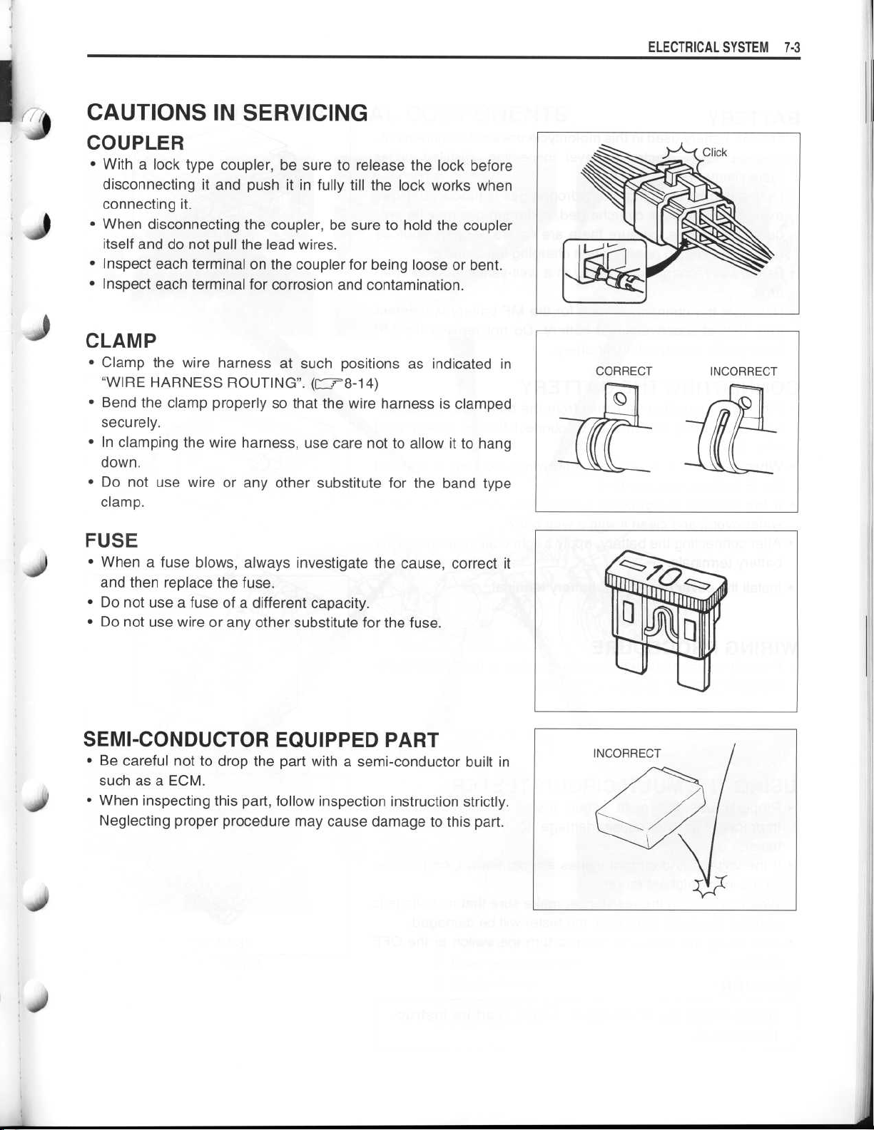
With a lock type coupler, be sure to release the lock before
disconnecting it and push it in fully till the lock works when
connecting it
•
When disconnecting the coupler, be sure to hold the coupler
itself and do not pull the lead wires
•
Inspect each terminal on the coupler for being loose or bent
•
Inspect each terminal for corrosion and contamination
CLAMP
•
Clamp the wire harness at such positions as indicated in
"WIRE HARNESS ROUTING"
•
Bend the clamp properly so that the wire harness is clamped
securely
•
In clamping the wire harness, use care not to allow it to hang
down
.
•
Do not use wire or any other substitute for the band type
clamp
.
.
.
.
.
.
-
78-14)
(C"
.
ELECTRICAL SYSTEM 7-
3
FUSE
•
When a fuse blows, always investigate the cause, correct it
and then replace the fuse
•
Do not use a fuse of a different capacity
•
Do not use wire or any other substitute for the fuse
.
.
.
SEMI-CONDUCTOR EQUIPPED PART
•
Be careful not to drop the part with a semi-conductor built in
such as a ECM
•
When inspecting this part, follow inspection instruction strictly
Neglecting proper procedure may cause damage to this part
.
.
.
Page 4
~
~
~
~
~
~
~
~
~
~
7-4 ELECTRICAL SYSTEM
BATTERY
•
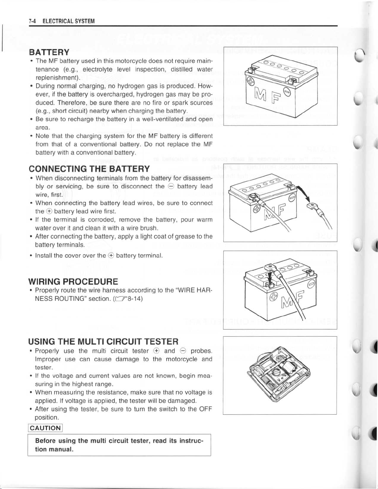
The MF battery used in this motorcycle does not require maintenance (e.g.,
replenishment)
•
During normal charging, no hydrogen gas is produced
ever, if the battery is overcharged, hydrogen gas may be produced
. Therefore, be sure there are no fire or spark sources
(e.g., short circuit) nearby when charging the battery
•
Be sure to recharge the battery in a well-ventilated and open
area
.
•
Note that the charging system for the MF battery is different
from that of a conventional battery
battery with a conventional battery
electrolyte level inspection, distilled water
.
. How-
.
. Do not replace the MF
.
CONNECTING THE BATTERY
•
When disconnecting terminals from the battery for disassem-
bly or servicing, be sure to disconnect the
wire, first
•
When connecting the battery lead wires, be sure to connect
theOObattery lead wire first
•
If the terminal is corroded, remove the battery, pour warm
water over it and clean it with a wire brush
•
After connecting the battery, apply a light coat of grease to the
battery terminals
•
Install the cover over the
.
.
.
.
battery terminal
O
battery lead
O
.
WIRING PROCEDURE
•
Properly route the wire harness according to the "WIRE HARNESS ROUTING" section
. (CJ8-14)
USING THE MULTI CIRCUIT TESTER
•
Properly use the multi circuit testerOand
Improper use can cause damage to the motorcycle and
tester
.
•
If the voltage and current values are not known, begin mea-
suring in the highest range
•
When measuring the resistance, make sure that no voltage is
applied
•
After using the tester, be sure to turn the switch to the OFF
position
CAUTION
Before using the multi circuit tester, read its instruc-
tion manual
. If voltage is applied, the tester will be damaged
.
.
.
e
probes
.
.
Page 5
~
~
~
~
ELECTRICAL SYSTEM 7-5
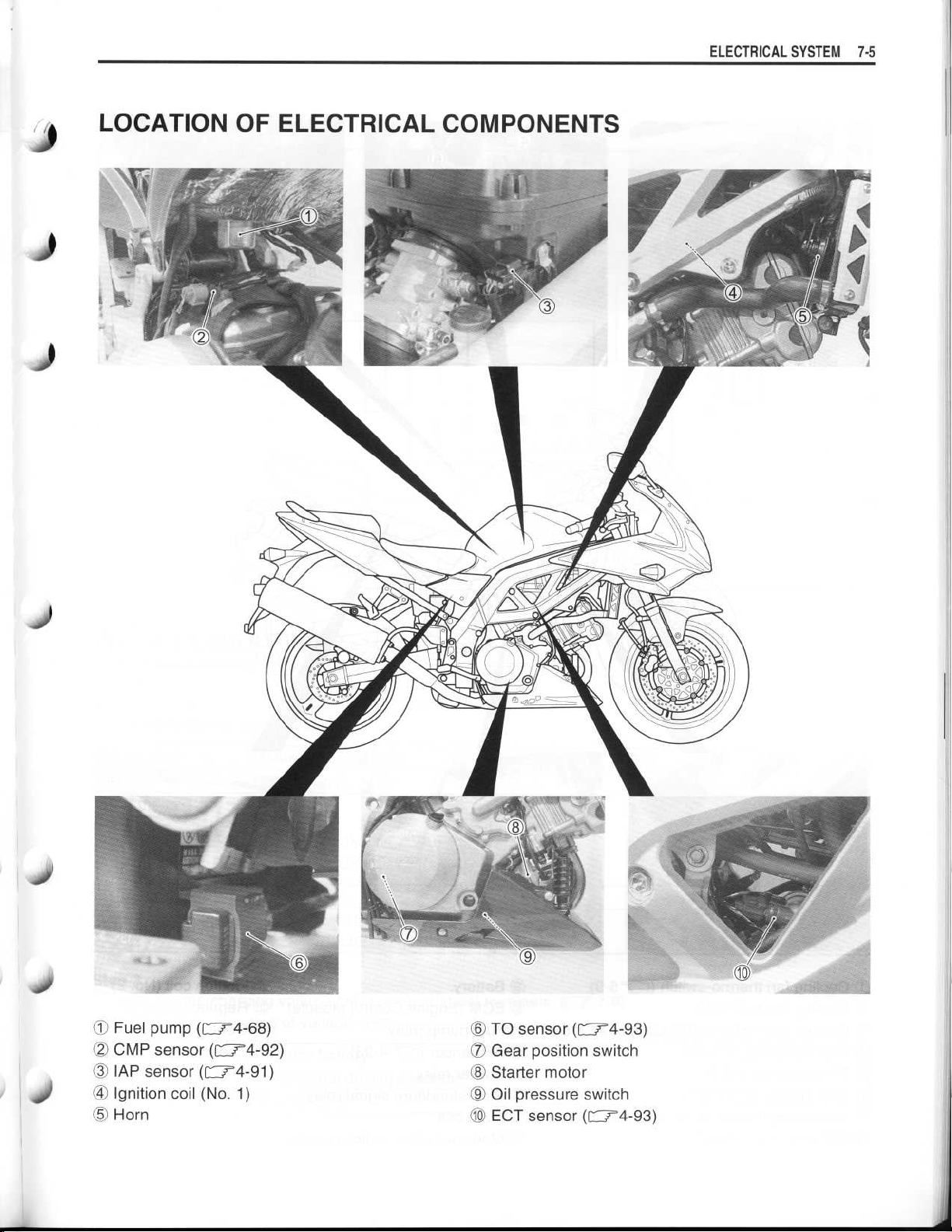
LOCATION OF ELECTRICAL COMPONENTS
~ 40
•
Fuel pump (C14-68)
02 CMP sensor (C'4-92)
~3 IAP sensor (=4-91)
Ignition coil (No
•
05 Horn
. 1)
® TO sensor (=4-93)
07 Gear position switch
Starter motor
•
Oil pressure switch
•
1o ECT sensor(f-
4-93)
4-93)
Page 6
~
~
~
~
~
~
~
~
7-6 ELECTRICAL SYSTEM
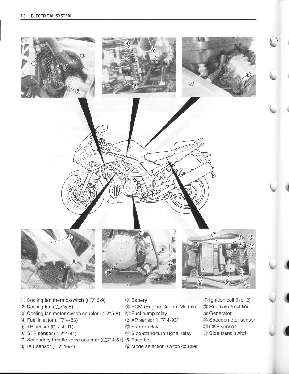
90 Cooling fan thermo-switch
Cooling fan
•
Cooling fan motor switch coupler (=5-8)
•
•
Fuel injector
~5 TP sensor (=4-91)
STP sensor
•
Secondary throttle valve actuator (=4-51)
•
IAT sensor
•
(r
-
75-8)
(r
--
74-86)
(f"74-91)
(r
--
74-92)
(
F-75-9)
O
10 ECM (Engine Control Module)
5-8)
0
13 Starter relay
14 Side-stand/turn signal relay
4-51) 15 Fuse box
16 Mode selection switch coupler
Battery
11 Fuel pump relay
AP sensor (=4-93)
4-93)
17 Ignition coil (No
18 Regulator/rectifier
19 Generator
20 Speedometer sensor
21 CKP sensor
22 Side stand switch
. 2)
Page 7
~
~
~
~
~
~
~
~
~
~
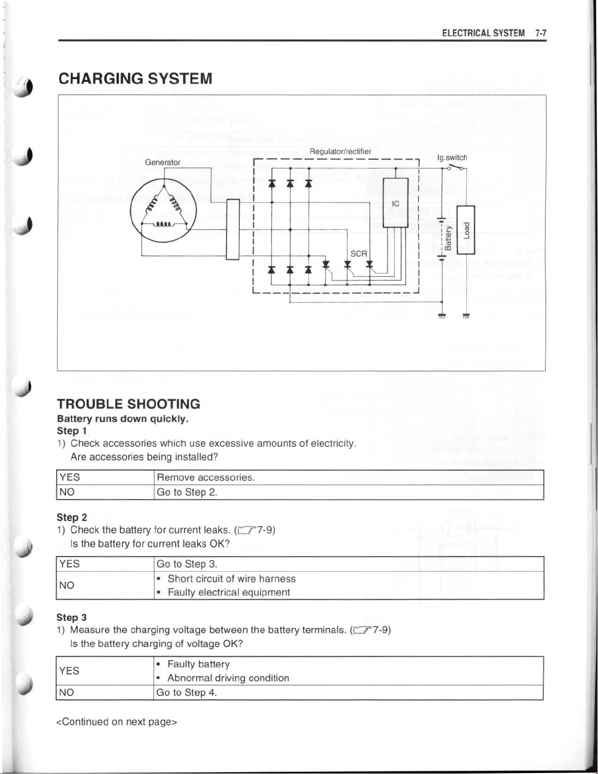
j CHARGING SYSTEM
ELECTRICAL SYSTEM 7-7
4)
4)
Regulator/rectifier
Generator
I
TROUBLE SHOOTING
Battery runs down quickly
.
I
I
I
I
I
I
I
.,
~
SCR
I
I
is
Step 1
1) Check accessories which use excessive amounts of electricity
.
Are accessories being installed?
Ig
l
.switch
I N
m
a
m
0
J
40
YES
NO
Remove accessories
Go to Step 2
.
.
Step 2
1) Check the battery for current leaks
. (=7-9)
Is the battery for current leaks OK?
YES
NO
Go to Step 3
Short circuit of wire harness
•
•
Faulty electrical equipment
.
Step 3
1) Measure the charging voltage between the battery terminals
. (11r7-9)
Is the battery charging of voltage OK?
Faulty battery
YES
NO
•
•
Abnormal driving condition
Go to Step 4
.
<Continued on next page>
Page 8
~
~
~
~
~
~
7-8 ELECTRICAL SYSTEM
Step 4
1) Measure the resistance of the generator coil
Is the resistance of generator coil OK?
. (=7-1 0)
YES
NO
Step 5
1) Measure the generator no-load voltage
Is the generator no-load voltage OK?
YES
NO
Step 6
1) Inspect the regulator/rectifier
Is the regulator/rectifier OK?
YES
NO
Step 7
1) Inspect the wirings
Are the wirings OK?
YES
NO
Go to Step 5
Faulty
Go to Step 6
Faulty
Go to Step 7
Faulty regulator/rectifier
.
Faulty battery
Short circuit of wire harness
•
•
Poor contact of couplers
.
generator
.
generator
.(I"
77-11)
.
coilordisconnected
. (C_r7-10)
lead~^.iros
Battery overcharge
•
Faulty regulator/rectifier
•
Faulty battery
•
Poor contact of generator lead wire coupler
Page 9
~
~
~
~
~
ELECTRICAL SYSTEM
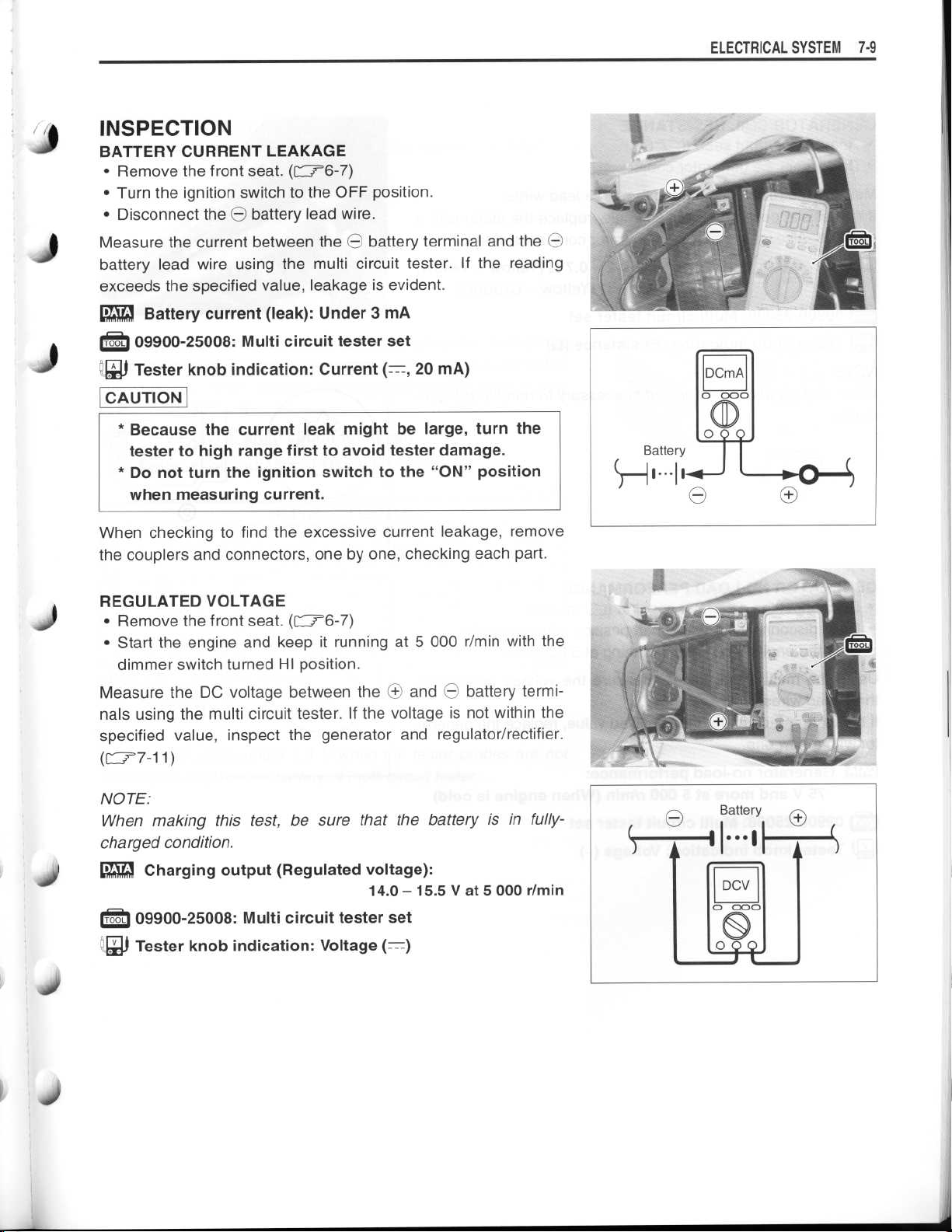
INSPECTION
j
BATTERY CURRENT LEAKAGE
Remove the front seat
•
•
Turn the ignition switch to the OFF position
•
Disconnect theObattery lead wire
Measure the current between the
battery lead wire using the multi circuit tester
exceeds the specified value, leakage is evident
Battery current (leak)
09900-25008
~j Tester knob indication
CAUTION
* Because the current leak might be large, turn the
tester to high range first to avoid tester damage
* Do not turn the ignition switch to the "ON" position
when measuring current
: Multi circuit tester set
. (=6-7)
: Under 3 mA
: Current
.
.
.
battery terminal and the
O
. If the reading
.
20 mA)
(-,
O
.
7-9
When checking to find the excessive current leakage, remove
the couplers and connectors, one by one, checking each part
REGULATED VOLTAGE
Remove the front seat.(r'6-7)
•
Start the engine and keep it running at 5 000 r/min with the
•
dimmer switch turned HI position
Measure the DC voltage between the
nals using the multi circuit tester
specified value, inspect the generator and regulator/rectifier
(r--r7-1
NOTE
When
charged condition
.
1)
:
making
Charging output (Regulated voltage)
.
09900-25008
Tester knob indication
this
test,besure
.
: Multi circuit tester set
.
and
O
. If the voltage is not within the
that
the
14.0- 15
: Voltage
(-)
battery termi-
O
battery is in fully-
:
.5 V at 5 000 r/m i n
.
.
Page 10
~
~
~
~
~
7
.10 ELECTRICAL SYSTEM
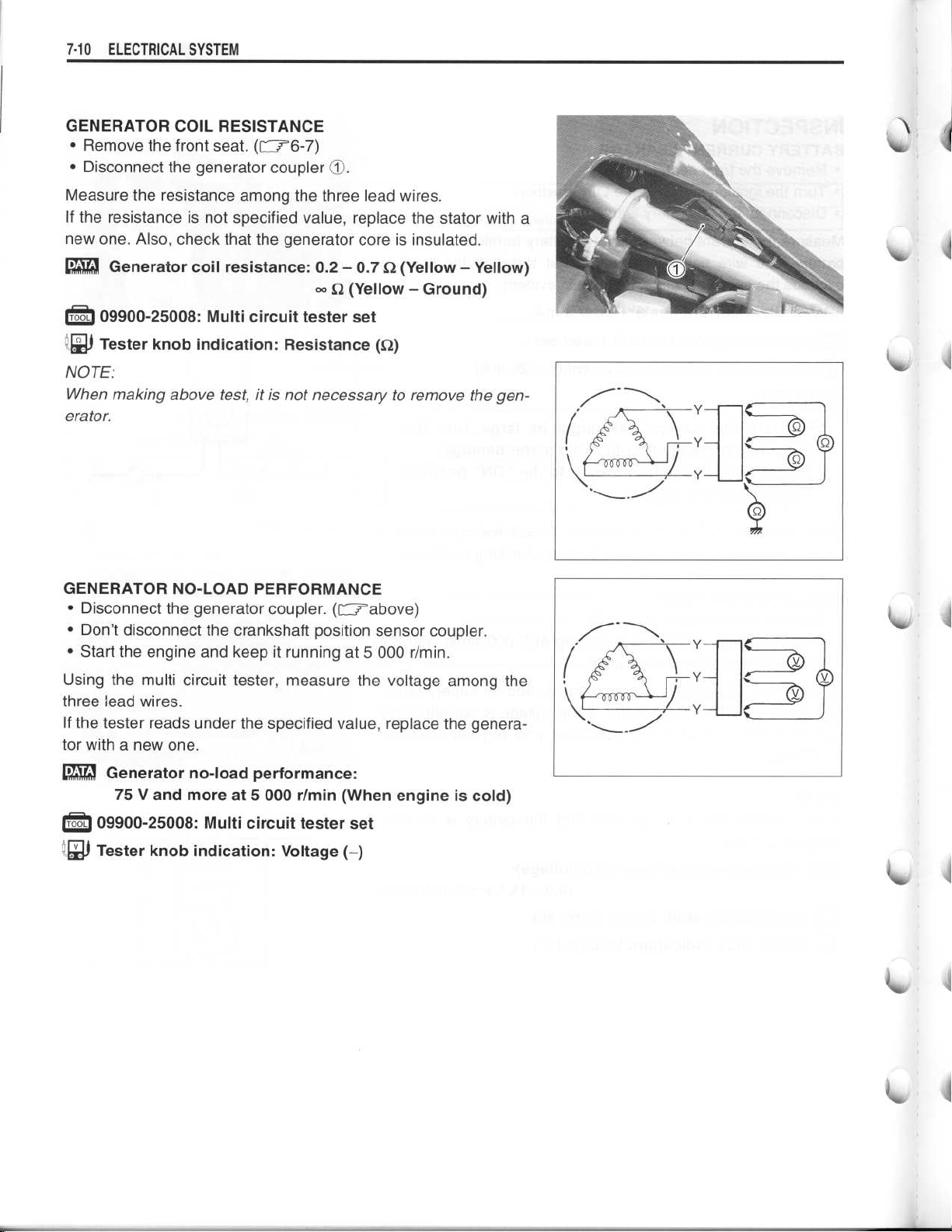
GENERATOR COIL RESISTANCE
•
Remove the front seat
•
Disconnect the generator coupler
Measure the resistance among the three lead wires
If the resistance is not specified value, replace the stator with a
new one
['~Generator coil resistance
. Also, check that the generator core is insulated
. (F-
76-7)
: 0.2- 0
D
.
.
(Yellow-Yellow)
.7 S2
-
S (Yellow-Ground)
.
09900-25008
Tester knob indication
ZJ
NOTE
:
When making above test, it is not necessary to remove the generator
.
GENERATOR NO-LOAD PERFORMANCE
•
Disconnect the generator coupler
•
Don't disconnect the crankshaft position sensor coupler
•
Start the engine and keep it running at 5 000 r/min
Using the multi circuit tester, measure the voltage among the
three lead wires
If the tester reads under the specified value, replace the generator with a new one
: Multi circuit tester set
: Resistance (S2)
. (Crabove)
.
.
.
.
A
A
A
Generator no-load performance
75 V and more at 5 000 r/min (When engine is cold)
09900-25008
Tester knob indication
: Multi circuit tester set
: Voltage
:
(-)
Page 11
~
~
I
4)
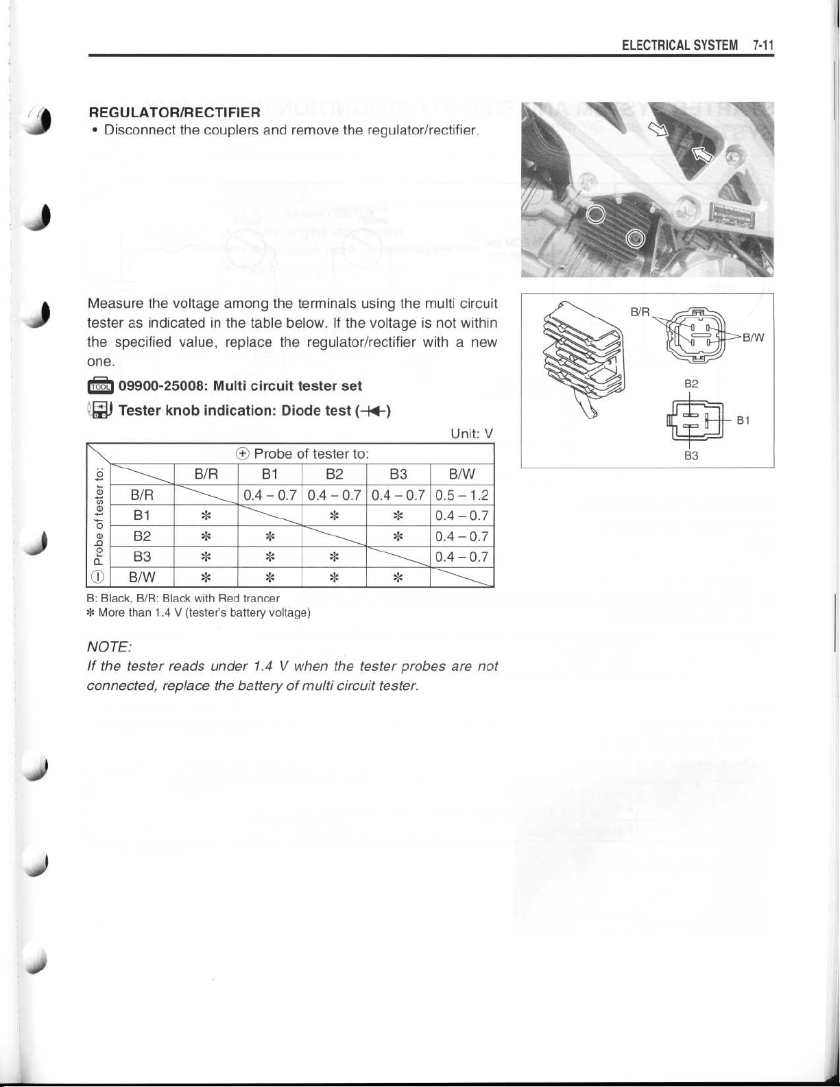
REGULATOR/RECTIFIER
•
Disconnect the couplers and remove the regulator/rectifier
Measure the voltage among the terminals using the multi circuit
tester as indicated in the table below
the specified value, replace the regulator/rectifier with a new
one
.
09900-25008
~$
Tester knob indication
g
~'
B/R
131
0
B2
B3
a
B/W
OI
B
: Black, B/R
* More than 1
: Black with Red trancer
.4 V (tester's battery voltage)
: Multi circuit tester set
: Diode test
Probe of tester to
O
B/R
*
*
131
0.4-0.70.4-0.70.4-0.70.5-1
*
. If the voltage is not within
(-W)
:
B2 B3
*
*
*
.
Unit
: V
B/W
.2
0
.4-0
.7
0
.4-0
.7
0.4-0.7
ELECTRICAL SYSTEM
7-11
NOTE
:
If the tester reads under 1
connected, replace the battery of multi circuit tester
.4 V when the tester probes are not
.
Page 12
~
~
~
7-12 ELECTRICAL SYSTEM
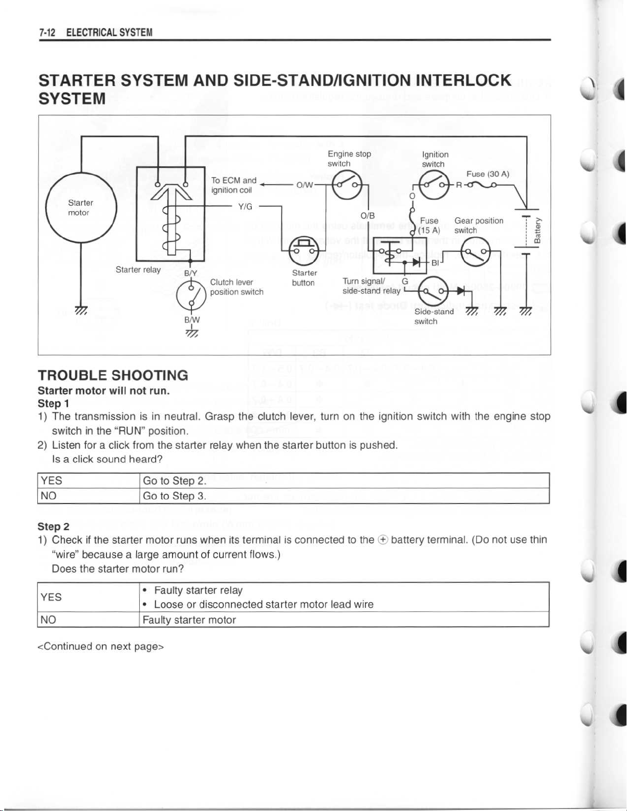
STARTER SYSTEM AND SIDE-STAND/IGNITION INTERLOCK
SYSTEM
Engine stop
switch
0
Starter
motor
Starter relay
To ECM and
0
ignition coil
B/Y
Clutch lever
position switch
B/W
I
Y/G
Starter
button
W
TROUBLE SHOOTING
Starter motor will not run
Step 1
1) The transmission is in neutral
switch in the "RUN" position
2) Listen for a click from the starter relay when the starter button is pushed
Is a click sound heard?
.
. Grasp the clutch lever, turn on the
ignition switch with the engine stop
.
Ignition
switch
Fuse (30 A)
.
ro
m
A
rr
In
J
YES
NO
Step 2
1) Check if the starter motor runs when its terminal is connected to the
"wire" because a large amount of current flows
Go to Step 2
Go to Step 3
.
.
.)
battery terminal
O
. (Do not use thin
Does the starter motor run?
Faulty starter relay
YES
NO
•
•
Loose or disconnected starter motor lead wire
Faulty starter motor
<Continued on next page>
Page 13

~
~
~
~
~
~
~
~
~
~
~
~
~
Step 3
1) Measure the starter relay voltage at the starter
starter button is pushed
Is the voltage OK?
YES
NO
Step 4
1) Check the starter relay.(F-t
Is the starter relay OK?
.
Go to Step 4
•
Faulty ignition switch
•
Faulty engine stop switch
•
Faulty clutch lever position switch
Faulty gear position switch
•
•
Faulty turn signal/side-stand relay
•
Faulty starter button
•
Poor contact of connector
•
Open circuit in wire harness
.
7-1 6)
relay connectors (between Y/GO+and B/YO)when the
ELECTRICAL SYSTEM7-1
3
YES
NO
NOTE
:
Poor contact of the starter relay
Faulty starter relay
The starter motor runs when the transmission is in neutral with the side-stand up or down, but does not run
when the transmission is in any position other than neutral with the side-stand down
2) Check the side-stand switch
Is the side-stand switch OK?
YES
NO
Engine does not turn though the starter motor runs
•
Faulty starter torque limiter (=3-64)
Open circuit in wire harness
•
•
Poor contact of connector
Faulty side-stand switch
. (CIT7-17)
.
.
STARTER MOTOR REMOVAL AND
DISASSEMBLY
•
Remove the under cowling
•
Disconnect the starter motor lead wire
starter motor
.
. (=6-5)
6-5)
90 and remove the
Page 14

~
~
~
~
7-14 ELECTRICAL SYSTEM
•
Disassemble the starter motor as shown in the illustration
.
0-ring
T
Housing
02
©3
Armature
Washer
•
0-ring
O5
Starter motor case
•
07 Starter brush holder assembly
0-ring
•
STARTER MOTOR INSPECTION
CARBON BRUSH
Inspect the brushes for abnormal wear, cracks, or smoothness
in the brush holder
If any damages are found, replace the brush assembly with a
new one
.
.
i
V
COMMUTATOR
Inspect the commutator for discoloration, abnormal wear or
undercut
If abnormal wear is found, replace the armature with a new one
OA
.
.
If the commutator surface is discolored, polish it with #400 sand
paper and wipe it using a clean dry cloth
.
If there is no undercut, scrape out the insulator 10 with a saw
blade
.
ARMATURE COIL INSPECTION
Check for continuity between each segment, and between each
segment and the armature shaft using the multi circuit tester
.
If there is no continuity between the segments or there is continuity between the segments and shaft, replace the armature
with a new one
09900-25008
i E
Tester knob indication
0
e
.
: Multi circuit tester set
: Continuity test
(
•I
)))
Page 15

~
~
~
~
~
ELECTRICAL SYSTEM 7-15
OIL SEAL INSPECTION
Check the oil seal lip for damage or leakage
If any damage is found, replace the housing end
.
.
J
STARTER MOTOR REASSEMBLY
l
Reassemble the starter motor in the reverse order of disassem-
bly
. Pay attention to the following points
•
Apply SUSUKI SUPER GREASE to the lip of the oil seal
:
.
99000-25030
99000-25010
•
Apply a small quantity of SUZUKI MOLY PASTE to the armature shaft
Apply a small quantity of THREAD LOCK to the starter motor
•
housing bolts
•
Apply SUZUKI SUPER GREASE to the O-ring
.
99000-25140
99000-32050
99000-25030
99000-25010
: SUZUKI SUPER GREASE "A" (USA)
: SUZUKI SUPER GREASE "A" (Others)
: SUZUKI MOLY PASTE
.
: THREAD LOCK "1342"
.
: SUZUKI SUPER GREASE "A" (USA)
: SUZUKI SUPER GREASE "A" (Others)
Tighten the starter motor lead wire nut to the specified torque
•
: 5 N
.m (0
Starter motor lead wire nut
19
.5 kgf-m, 3
.7 Ib-ft)
.
Page 16

~
~
~
~
~
~
7-16 ELECTRICAL SYSTEM
STARTER RELAY INSPECTION
•
Remove the front seat.(F--r6-7)
•
Disconnect theObattery lead wire from the battery
•
Disconnect the starter relay coupler 1O
•
Remove the starter relay cover 02
.
.
.
•
Disconnect the starter motor lead wire
wire ®
•
Remove the starter relay 05
Apply 12 V to ® and © terminals and check for continuity
between the positive and negative terminals using the multi circuit tester
relay is OK
CAUTION
Do not apply a battery voltage to the starter relay for
more than five seconds, since the relay coil may overheat and damaged
.
.
. If the starter relay clicks and continuity is found, the
.
09900-25008
Tester knob indication
: Multi circuit tester set
: Continuity test (
.
and battery lead
(s
•~
l))
Measure the relay coil resistance between the terminals using
the multi circuit tester
value, replace the starter relay with a new one
Starter relay resistance
. .
09900-25008
~y Tester knob indication
. If the resistance is not within the specified
.
: 3 - 6
: Multi circuit tester set
: Resistance (SZ)
SZ
Page 17

~
~
~
~
J
SIDE-STAND/IGNITION INTERLOCK
SYSTEM PARTS INSPECTION
Check the interlock system for proper operation
system does not operate properly, check each component for
damage or abnormalities
the component with a new one
SIDE-STAND SWITCH
•
Lift and support the fuel tank
•
Disconnect the side-stand switch coupler and measure the
voltage between Green and Black/Yellow lead wires
09900-25008
P71
i
Tester knob indication
ON
(Side-stand up)
OFF
(Side-stand down)
: Multi circuit tester set
. If any abnormality is found, replace
.
.
(
F-74-65)
: Diode test (-~W)
Green
(O+
Probe)
0 .4
-
1
.4 V and more
(Tester's battery voltage)
. If the interlock
.
Black/Yellow
Probe)
(O
0
.6 V
ELECTRICAL SYSTEM 7-
1
7
NOTE
:
If the tester reads under 1
connected, replace its battery
GEAR POSITION SWITCH
•
Lift and support the fuel tank
•
Disconnect the gear position switch coupler and check the
continuity between Blue and Black with the transmission in
"NEUTRAL"
ON (Neutral)
OFF (Expect neutral)
CAUTION
When disconnecting and connecting the gear position
switch coupler, make sure to turn OFF the ignition
switch, or electronic parts may get damaged
.
.4 V when the tester probes are not
.
.
(r
-
74-65)
Blue
0
Black
0
.
Down
Page 18

~
~
~
~
7-18
ELECTRICAL SYSTEM
•
Connect the gear position switch coupler to the wiring harness
.
•
Turn the ignition switch to "ON" position and side-stand to
upright position
Measure the voltage between Pink and Black lead wires using
the multi circuit tester when shifting the gearshift lever from low
to top
.
.
Gear position switch voltage
(* Low to top gear position)
(*
Except neutral position)
09900-25008
09900-25009
1
711
Tester knob indication
TURN SIGNAL/SIDE-STAND RELAY
The turn signal/side-stand relay is composed of the turn signal
relay, and the side-stand relay and diode
•
Remove the front seat
•
Remove the turn signal/side-stand relay
SIDE-STAND RELAY INSPECTION
First check the insulation betweenOandOterminals with the
tester
. Then apply 12 V to terminalsODand ©
©) and check the continuity betweenODand
continuity, replace the turn signal/side-stand relay with a new
one
.
.
.
09900-25008
: Multi circuit tester set
: Needle pointed probe set
: Voltage
. (=6-7)
6-7)
: Multi circuit tester set
.6 V and more
: 0
(Pink-Black)
(--)
.
.
(
O+
toOandOto
(e
.
If there is no
Tester knob indication
e
0
: Continuity test
(•))))
Page 19

~
~
ELECTRICAL SYSTEM 7-
DIODE INSPECTION
J
~
Measure the voltage between the terminals using the multi cir-
cuit tester
0
0
0
0
0-
go
NOTE
If the multi circuit tester reads under 1
probes are not connected, replace its battery
. Refer to the following table
Probe of tester to
©, ©
~
0
©, ©
0
.4-0
.6
09900-25008
Tester knob indication
:
: Multi circuit tester set
: Diode test
.
Unit
:
OO
More than 1
(Tester's battery
voltage)
(-W)
.4 V when the tester
.
.4 V
: V
iii
© OO
1 9
Page 20

~
~
7-20
ELECTRICAL SYSTEM
IGNITION SYSTEM
Engine stop switch
0
CKP
sensor
I
I
1 0
I
Cam position
sensor
ECM
Power
source
circuit
0
Wave form
arrangement
circuit
Wave form
arrangement
circuit
Throttle
position
sensor
CPU
Engine
coolant temp
sensor
.
Gear
position
switch
Ignition
coil
0
t 0
a
00
0
°
o
'ta
Spark plug
#1
#2
m m
Side-
b
standstand
relay
Fuse
Ignition
switch
Fuse
Battery
V
NOTE
:
The fuel cut-off circuit is incorporated in this ECM in order to prevent over-running of engine
speed reaches 10 600 r/min, this circuit cuts off fuel at the fuel injector
.
. When engine
CAUTION
Under no load, the engine can run over 10 600 r/min, even if the fuel cut-off circuit is effective,
and it may cause engine damage
time
.
. Do not run the engine without load over 10 600 r/min at any-
TROUBLESHOOTING
NOTE
:
Check that the transmission is in neutral and the engine stop switch is in the "RUN" position
lever
. Check that the fuse is not blown and the battery is fully-charged before diagnosing
No spark or poor spark
Step 1
1) Check the ignition system couplers for poor connections
.
Is there connection in the ignition switch couplers?
YES
NO
Go to Step 2
.
Poor connection of couplers
. Pull the clutch
.
<Continued on next page>
Page 21

~
~
~
~
~
~
~
~
ELECTRICAL SYSTEM 7-21
Step 2
1) Measure the battery voltage between input lead wires (O/W and B/W) at the ECM with the ignition switch
in the "ON" position
Is the voltage OK?
.
YES
NO
Step 3
1) Measure the ignition coil primary peak voltage
NOTE
:
This inspection method is applicable only with the multi circuit tester and the peak volt adaptor
Is the peak voltage OK?
YES
NO
Step 4
1) Inspect the spark plugs
Are the spark plugs OK?
YES
NO
Go to Step 3
•
Faulty ignition switch
Faulty turn signal/side-stand relay
•
•
Faulty engine stop switch
•
Broken wire harness or poor connection of related circuit couplers
Go to Step 4
Go to Step 5
. (=2-6)
Poor connection of the spark plug cap
•
•
Go to Step 5
Faulty spark plug
.
.
.
2-6)
.
(-s)
.(f"
77-22)
.
(-s)
Step 5
1) Inspect the ignition coils
Are the ignition coils OK?
YES
NO
Step 6
1) Measure the crankshaft position sensor peak voltage and its resistance
NOTE
:
The crankshaft position
peak volt adaptor
Are the peak voltage and its resistance OK?
YES
NO
.
. (E177-23)
Go to Step 6
Faulty ignition coil
sensor
Faulty ECM
•
•
Poor connection of ignition couplers
Faulty crankshaft position sensor
.
(-s)
peak voltage inspection is applicable only with the mufti circuit tester and
.
Page 22

~
~
~
~
~
~
~
~
~
~
7-22
ELECTRICAL SYSTEM
INSPECTION
IGNITION COIL PRIMARY PEAK VOLTAGE
•
Lift and support the fuel tank.(l1_,,--4-65)
•
Disconnect both of the spark plug caps.(f'72-6)
•
Connect new spark plugs to each spark plug cap and ground
them
.
NOTE
:
Make sure that all couplers and spark plugs are connected properly and the battery used is in fully-charged condition
CAUTION
Avoid grounding the spark plugs and suppling the
electrical shock to the cylinder head cover (magnesium parts) in order to prevent the magnesium material from damage
.
.
Measure the No
in the following procedure
Connect the multi circuit tester with peak voltage adaptor as
•
follows
No
.
. 1 ignition coil
. 1 and No
:OOProbe
•
No
. 2 ignition coil
:OOProbe
•
NOTE
:
Do not disconnect the ignition coil primary wire coupler
. .
09900-25008
CAUTION
Before using the multi circuit tester and peak volt
adaptor, be sure to refer to the appropriate instruction
manual
•
Shift the transmission into neutral
•
Allow the engine to crank for a few seconds, and then measure the ignition coil primary peak voltage
.
: Multi circuit tester set
. 2 ignition coils primary peak voltage
.
: Black terminal
Probe
: Ground
: White/Blue terminal
Probe
: Ground
.
.
.
r
In
•
Repeat the above procedure a few times and measure the
highest ignition coil primary peak voltage
Ignition coil primary peak voltage
Tester knob indication
WARNING
A
While testing, do not touch the tester probes and
spark plugs to prevent receiving an electric shock
•
If the peak voltage is lower than the specified values, inspect
the ignition coil.(F---r7-23)
: Voltage
.
: 200 V and more
(--)
.
Page 23

~
~(~
~
~
~
ELECTRICAL SYSTEM 7-23
IGNITION COIL RESISTANCE
•
J
Disconnect the spark plug caps
Measure the ignition coil resistance in both the primary and sec-
ondary windings
range, replace the ignition coil with a new one
. If the resistance is not within the standard
.
.
1
Ignition coil resistance
Primary
Secondary
09900-25008
Tester knob indication : Resistance
CKP SENSOR PEAK VOLTAGE
•
Remove the front seat
•
Disconnect the ECM coupler
NOTE
:
Make sure that all of the couplers are connected properly and
the battery used is in fully-charged condition
: 2.8-4.2 S2
: 24 -
: Multi circuit tester set
((O
terminal -Sterminal)
36 kL2 (Plug cap
. (116-7)
.
-Oterminal)
(4)
.
Measure the CKP sensor peak voltage in the following procedures
.
•
Connect the multi circuit tester with peak volt adaptor as fol-
lows
.
O
Probe
: Green/Blue lead wire
Probe
9
. .
09900-25008
CAUTION
Before using the multi circuit tester and peak volt
adaptor, be sure to refer to the appropriate instruction
manual
: Green lead wire
: Multi circuit tester set
.
Page 24

~
~
~
~
~
~
~
~
7-
2 4
ELECTRICAL SYSTEM
•
Shift the transmission into neutral
•
Allow the engine to crank for a few seconds, and then measure the CKP sensor peak voltage
•
Repeat the above procedure a few times and measure the
highest peak voltage
[
CKP sensor peak voltage
I
rPli
Tester knob indication
If the peak voltage is lower than the specified values, check the
peak voltage at the CKP sensor lead wire coupler
•
Disconnect the CKP sensor lead wire coupler and connect the
multi circuit tester with the peak volt adaptor
•
Probe
: Green lead wire
Probe
•
•
Measure the CKP sensor peak voltage at the CKP sensor
lead wire coupler in the same manner as on the ECM coupler
: Blue lead wire
.
: Voltage
.
.
: 5
.0 V and more
(-)
(Z
.
.
.
CKP sensor peak voltage
Tester knob indication
~,~
If the peak voltage on the CKP sensor lead wire coupler is OK
but on the ECM coupler is out of specification, the wire harness
must be replaced
the CKP sensor must be replaced and re-checked
CKP SENSOR RESISTANCE
Measure the resistance between the lead wires and ground
the resistance is not specified value, the CKP sensor must be
replaced
.
CKP sensor resistance
09900-25008
Tester knob indication
. If both peak voltages are out of specification,
: Multi circuit tester set
: 5
.0 V and more
: Voltage
: 130 -
W Q (Green -
: Resistance (S2)
(-)
240 Q (Green-Blue)
Ground)
.
. If
Page 25

~
~
~
~
COMBINATION METER
ELECTRICAL SYSTEM
J)
Conbination meter cover
Conbination meter unit
(2
7- 2
5
REMOVAL
•
Remove the body cowling
•
Remove the meter panel mounting bolts and disconnect the
meter coupler 1T
CAUTION
•
When disconnecting and connecting the combination meter coupler, make sure to turn OFF the ignition switch, or electronic parts may get damaged
•
Do not attempt to disassemble the combination
meter unit
.
.
.
(r
--
r6-6)
.
Page 26

~
~
~
~
~
~
~
7-26
ELECTRICAL SYSTEM
PARTS NAME
10 Turn signal indicator light
(2
Neutral indicator light
(3 Indicator light (Oil, Temp
•
SELECT button
•
Clock
Coolant temperature/Fl display
•
(7
Odo/Trip meter display
•
ADJUST button
~9 Fuel indicator light
1o High beam indicator light
., FI)
OPERATING PROCEDURE
INITIAL DISPLAY
When the ignition switch is turned to ON, the indicator light
andOcome on, then ©9 goes out two seconds later
NOTE
:
If the
power supply is cut (e, g, when the battery is replaced)
* The speedometer, tripmeter and clock are displayed after the
initial display appears
* Since the clock resets to
.
"1
:00",
it will need to be readjusted
CHANGE THE DISPLAY MODE
With each press of the SELECT button, the display changes
between odometer, tripmeter A and tripmeter B as shown
WARNING
A
Odometer
-n
Tripmeter A~~ Tripmeter
To avoid riding with only one hand, do not operate the
buttons while riding
.
ODOMETER
•
Displays the total distance travelled
.
:
.
.
B1-
1
TRIPMETER
•
Displays the distance travelled since the tripmeter was last
reset
NOTE
:
The tripmeters A and B can be used independently
Hold down the ADJUST button for two seconds to reset the
•
tripmeter
.
.
Page 27

~
~
CLOCK
•
Displays the time (hours and minutes) on a 12-hour clock
•
Setting the time
10 Push the SELECT and ADJUST buttons simultaneously until
the hour display starts blinking
02 Adjust the hour display by pushing the ADJUST button
NOTE
:
.
.
When the ADJUST button is kept depressed for more than two
seconds, the display progresses continuously
03 Push the SELECT button
changed
.
. The setting that is blinking can be
.
ELECTRICAL SYSTEM 7-
ADJ
2 7
® Adjust the minute display by pushing the ADJUST button
($ Push the SELECT button to finish setting time
.
.
TACHOMETER
•
The tachometer pointer operates one time as shown below to
reset tachometer pointer, when connecting the
tachometer coupler
i
.
battery or
Page 28

~
~
~
~
7-28 ELECTRICAL SYSTEM
ENGINE COOLANT TEMPERATURE METER
AND INDICATOR
•
Disconnect the engine coolant temperature sensor coupler
CAUTION
When connecting and disconnecting the engine coolant temp
OFF the ignition switch, or electronic parts may get
damaged
•
Connect the variable resistor
•
Turn the ignition switch "ON"
•
Check the LCD and LED operations when the resistance is
adjusted to the specified values
. sensor lead wire coupler, make sure to turn
.
between the terminals
OO
.
.
.
.
Engine
coolant
temp
.
Variable resister
sensor
Resistance
AO
Over 2
(Jumper wire)
If either one or all indications are abnormal, replace the combi-
nation meter with a new one
NOTE
If the engine stop switch is turned OFF while the ignition switch
is ON, the LCD displays "CHEC"
This condition implies that combination meter receives no signal
from the ECM
In that case, they are restored to ordinary indication by turning
the engine stop switch RUN
.45 kS
Approx
0
.811 kS2
Approx
0
.1 kS2
0c
:
LED © LCD ©
OFF
.
OFF
.
ON
ON
.
---
"50"
"120"-"139"
"HI"
.
. But it is not malfunction
.
LCD
0
-
Flicker
Flicker
Water
temperature
Under 19 °C
Approx
120-139
Over 140 °C
50 °C
.
.
0
C
Page 29

~
~
~
~
1
FUEL LEVEL INDICATOR SWITCH INSPECTION
. (=4-69)
•
Remove the fuel pump assembly
•
Connect 12 V battery and test bulb (12 V, 3
level indicator switch as shown in the right illustrations
bulb should come on after several seconds if the switch is in
good condition
.
4-69)
.4 W) to the fuel
. The
ELECTRICAL SYSTEM 7-
29
•
When the switch is immersed in water under the above condition, the bulb should go out
unit with a new one
FUEL LEVEL INDICATOR LIGHT INSPECTION
If the fuel level indicator light does not function properly, check
the fuel level indicator switch and its lead wire/coupler
If the fuel level indicator switch and its lead wire/coupler are all
right, replace the combination meter with a new one
OIL PRESSURE INDICATOR
NOTE
:
Before inspecting the oil pressure switch, check the engine oil
level.(rr2-15)
.
. If the bulb remains it, replace the
.
.
•
Remove the under cowling
•
Disconnect the oil pressure switch lead wire from the oil pres-
sure switch
•
Turn the ignition switch "ON" position
.
.(C7-6-5)
.
Page 30

~
~
~
7
.30 ELECTRICAL SYSTEM
Check if the oil pressure indicator will light, when grounding the
lead wire
replace the meter with a new one after checking the connection
of couplers
SPEEDOMETER
If the speedometer, odometer or trip meter does not function
properly, inspect the speedometer sensor and connection of
coupler 1)
right, replace the meter with a new one
. If the oil pressure indicator does not function properly,
.
. If the speedometer sensor and connection are all
.
SPEEDOMETER SENSOR
•
Disconnect speedometer sensor coupler
•
Remove the speedometer sensor (2 by removing its mounting
bolt
.
•
Connect 12 V battery, 10 kQ resistor and the multi circuit
tester as shown in the right illustration
B/R
: Black with Red tracer
B/W
: Black with White tracer
B
: Black
:
.
09900-25008
Tester knob indication
•
Under above condition, if a suitable screwdriver touching the
pick-up surface of the speedometer sensor is moved, the
tester reading voltage changes (0 V
the tester reading voltage does not change, replace the
speedometer sensor with a new one
NOTE
:
The highest voltage reading in this test will be the same as that
of battery voltage
: Multi circuit tester set
: Voltage
.
.
.
(=)
- 12 V or 12 V -
.
0 V)
. If
Page 31

~
~
~
~
LAMPS
HEADLIGHT AND POSITION LIGHT
ELECTRICAL SYSTEM7-3
10
Head light
12 V 60/55 W x 2
(2 Position light
12 V 5 W x 2
1
l
BULB REPLACEMENT
Headlight
•
Remove the headlight coupler and boot
•
Unhook the holder spring 9I and replace the headlight bulb
Position light
•
Open the lids
•
Remove the position light couplers 10
. (L & R)
.
. (L & R)
.
CAUTION
If you touch the bulb with your bare hands, clean the
bulb with a cloth moistened with alcohol or soapy
water to prevent premature bulb failure
.
Page 32

~
~
7-32
ELECTRICAL
HEADLIGHT BEAM ADJUSTMENT
Adjust the headlight beam, both vertical and horizontal
•
Turn the adjuster
NOTE
:
To adjust the headlight beam, adjust the beam horizontally first,
then adjust the vertically
•
Turn the bolt © for the vertical adjustment
SYSTEM
for the horizontal adjustment
OA
.
.
.
.
BRAKE LIGHT/TAILLIGHT, TURN SIGNAL LIGHT AND LICENCE PLATE
LIGHT
Page 33

RELAYS
TURN SIGNAL/SIDE-STAND RELAY
The turn signal/side-stand relay is composed of the turn signal
relay, side-stand relay and diode
INSPECTION
Before removing the turn signal/side-stand relay, check the
operation of the turn signal light
If the turn signal light does not illuminate, inspect the bulb, turn
signal switch and circuit connection
If the bulb, turn signal switch and circuit connection are OK, the
turn signal relay may be faulty
side-stand relay with a new one
NOTE
:
* Make sure that the battery is fully charged
* Refer to page 7-17 for the side-stand relay and diode inspec-
tion
.
.
.
.
; therefore, replace the turn signal/
.
.
ELECTRICAL SYSTEM 7-33
T)
SIDE-STAND RELAY
TURN
SIGNAL
RELAY
4)
STARTER RELAY
r -
77-1
6
FUEL PUMP RELAY
17'4-69
Page 34

~
~
~
~
~
7-34
ELECTRICAL SYSTEM
SWITCHES
IGNITION SWITCH REMOVAL
•
Lift and support the fuel tank
•
Remove the air cleaner box.(F
•
Disconnect the ignition switch coupler
•
Remove the body cowling.(
•
Remove the ignition switch mounting bolts with the special
tools
.
. (=4-65)
74-75)
--
r -
76-6)
.
09930-11920
09930-11940
CAUTION
When reusing the ignition switch bolt, clean thread and
apply THREAD LOCK
99000-32050
: Torx bit JT40H
: Bit holder
.
: THREAD LOCK "1342"
Page 35

~
~
ELECTRICAL SYSTEM 7.3 5
J
J
Inspect each switch for continuity with the multi circuit tester
tive switch assemblies with new ones
09900-25008
IGNITION
Position
ON
P
DIMMER SWITCH
Position
HI (=D)
LO (D)
TURN SIGNAL SWITCH
Position
L
PUSH
R
PASSING LIGHT SWITCH
Position
PUSH
ENGINE STOP SWICH
Position
OFF (>Z)
RUN (0)
STARTER BUTTON
Position
PUSH
HORN BUTTON
Position
PUSH
SWITCH
Color
Color
Color
Color
Color
Color
Color
: Multi circuit tester set
R
W
0 0
Lg
0
0
y
0 0
Lbl
0 0
0
0 Y
O/B
0
O/W
0
13/131
0
ON
.
Br
0
B
O/W
Y/G
B/W
. If any abnormality is found, replace the respec-
HAZARD
Color
Position
ON
OFF
FRONT BRAKE SWITCH
Color
Position
OFF
ON
REAR BRAKE SWITCH
Color
Position
OFF
ON
CLUTCH LEVER POSITION SWITCH
Color
Position
OFF
ON
OIL PRESSURE SWITCH
Color
Position
ON (engine
is stopped)
OFF (engine
is running)
NOTE
:
Before inspecting the oil pressure switch, check the
engine oil level
WIRE COLOR
B~:
Black
Br
: Brown
LbI
: Light blue
Lg
: Light green
0
:
Orange
R
:
Red
Y~:
Yellow
W
: White
Lg
0
B/R
O/G
B/Y
G/Y Ground
. (C72-15)
Lbl
0
0 0
W/B
0
O O
B/BI
: Black with Blue tracer
B/W
: Black with White tracer
B/Y
: Black with Yellow tracer
B/R
: Black with Red tracer
G/Y
: Green with Yellow tracer
O/B
: Orange with Black tracer
O/G
: Orange with Green tracer
O/W
: Orange with White tracer
ON
:Orange with Yellow tracer
W/B
: White with Black tracer
Y/G
: Yellow with Green tracer
B
0
B/BI
0
B/Y
Page 36

~
~
~
~
~
~
~
~
~
7-36
ELECTRICAL SYSTEM
BATTERY
SPECIFICATIONS
Type designation
Capacity
Anode plates
•
Separator (fiberglass plate)
•
Cathode plates
•
Upper cover breather
•
12 V, 43
FTX14-BS
.2 kC (12 Ah)/10 HR
© Stopper
Filter
•
Terminal
•
•
Safety valve
INITIAL CHARGING
FILLING ELECTROLYTE
•
Remove the aluminum tape 10 sealing the battery electrolyte
filler holes 02
•
Remove the caps
.
(T
.
NOTE
:
* After filling the electrolyte completely, use the removed caps
O3 as the sealed caps of battery filler holes
* Do not remove or pierce the sealed areas ® of the electrolyte
container
•
Insert the nozzles of the electrolyte container ($ into the bat-
tery's electrolyte filler holes, holding the container firmly so
that it does not fall
fluid to spill
.
. Take precaution not to allow any of the
.
.
IN
V
Page 37

~
~
~
ELECTRICAL SYSTEM7-37
•
Make sure air bubbles © are coming up each electrolyte con-
tainer, and leave in this position for about more than 20 min-
0
O
oV
0
0
J
°
0
L)
U
O
o
Vo
0
U
O
O
°
o
I
0
H,
I
U
0
O
o
0
U
G
V
0
Go
G
oU
0
0G
~`
1
utes
.
NOTE
:
If on air bubbles are coming up from a filler port, tap the bottom
of the electrolyte container two or three times
Never remove the container from the battery
•
After confirming that the electrolyte has entered the battery
completely, remove the electrolyte containers from the bat-
tery
. Wait for about more than 20 minutes
.
.
.
l
•
Insert the caps O7 into the filler holes, pressing in firmly so that
the top of the caps do not protrude above the upper surface of
the battery's top cover
CAUTION
•
Never use anything except the specified battery
•
Once install the caps to the battery
the caps
•
Do not tap the caps with a hammer when installing
them
.
.
.
.
; do not remove
Page 38

~
~
~
~
~
~
~
~
7-
ELECTRICAL SYSTEM
3
8
•
For initial charging, use the charger specially designed for MF
battery
CAUTION
•
•
•
.
For charging the battery, make sure to use the
charger specially designed for MF battery
wise, the battery may be overcharged resulting in
shortened service life
Do not remove the cap during charging
Position the battery with the cap facing upward during charging
.
.
. Other-
.
SERVICING
Visually inspect the surface of the battery container
of cracking or electrolyte leakage from the sides of the battery
have occurred, replace the battery with a new one
terminals are found to be coated with rust or an acidic white
powdery substance, clean the battery terminals with sandpaper
. If any signs
. If the battery
.
RECHARGING OPERATION
•
Measure the battery voltage using the multi circuit tester
the voltage reading
battery with a battery charger
CAUTION
When recharging the battery, remove the battery from
the motorcycle
NOTE
:
While recharging, do not remove the caps on the top of the bat-
tery
.
Recharging time
CAUTION
Be careful not to permit the charging current to
exceed 6 A at any time
•
After recharging, wait at least 30 minutes and then measure
the battery voltage using the multi circuit tester
voltage is less than 12
battery voltage is still less than 12
replace the battery with a new one
•
When a battery is left unused for a long time, its voltage
needs to be regularly measured
used for more than one month (especially during the winter
season), measure the battery voltage at least once a month
is less
.
: 1
.4 A for 5 to 10 hours or 6 A for 1 hour
than the
.
.
.5 V, recharge the battery again
12 V
.5 V after recharging,
.
. When the motorcycle is not
recharge the
(DC),
. If the battery
. If
. If the
.
Charging period
(V)
18
17
16
15
14 13
12
0 10
Stop charging
20
30 40 50
Time
60
(Minutes)
 Loading...