

Page 1
EMISSION CONTROL INFORMATION
EMISSION CONTROL INFORMATION
CONTENTS
9-1
01
0
0
EMISSION CONTROL SYSTEMS
FUEL INJECTION SYSTEM
CRANKCASE EMISSION CONTROL SYSTEM
EXHAUST EMISSION CONTROL
NOISE EMISSION CONTROL SYSTEM
EVAPORATIVE EMISSION CONTROL SYSTEM (FOR E-33)
PAIR (AIR SUPPLY) SYSTEM INSPECTION
HOSES
PAIR REED VALVE
PAIR CONTROL SOLENOID VALVE
PAIR (AIR SUPPLY) SYSTEM HOSE ROUTING
HEATED
EVAPORATIVE EMISSION CONTROL SYSTEM INSPECTION
(FOR E-33)
HOSES
EVAP CANISTER
TANK PRESSURE CONTROL VALVE
EVAP CANISTER HOSE ROUTING (FOR E-33)
~
OXGEN
~
~
~
SENSOR (HO2S) INSPECTION (FOR E-02,19)
~
~
~
~
SYSTEM (PAIR SYSTEM)
~
~
~
~
~
~
9- 2
2
99- 3
~
~
~
9- 4
9- 5
9- 5
9- 6
9- 6
9- 6
9- 6
9- 8
9- 9
9-10
9-10
9-10
9-10
9-11
0
It
9
Page 2

9-2
EMISSION CONTROL INFORMATION
EMISSION CONTROL SYSTEMS
FUEL INJECTION SYSTEM
SV1000S motorcycles are equipped with a fuel injection system for emission level control
This fuel injection system is precision designed, manufactured and adjusted to comply with the applicable
emission limits
.
.
~%~~~
~
BEFORE-PRESSURIZED
FUEL
PRESSURIZED FUEL
RELIEVED FUEL
I'
Ift
Page 3
~
0
0
9
EMISSION CONTROL INFORMATION 9-3
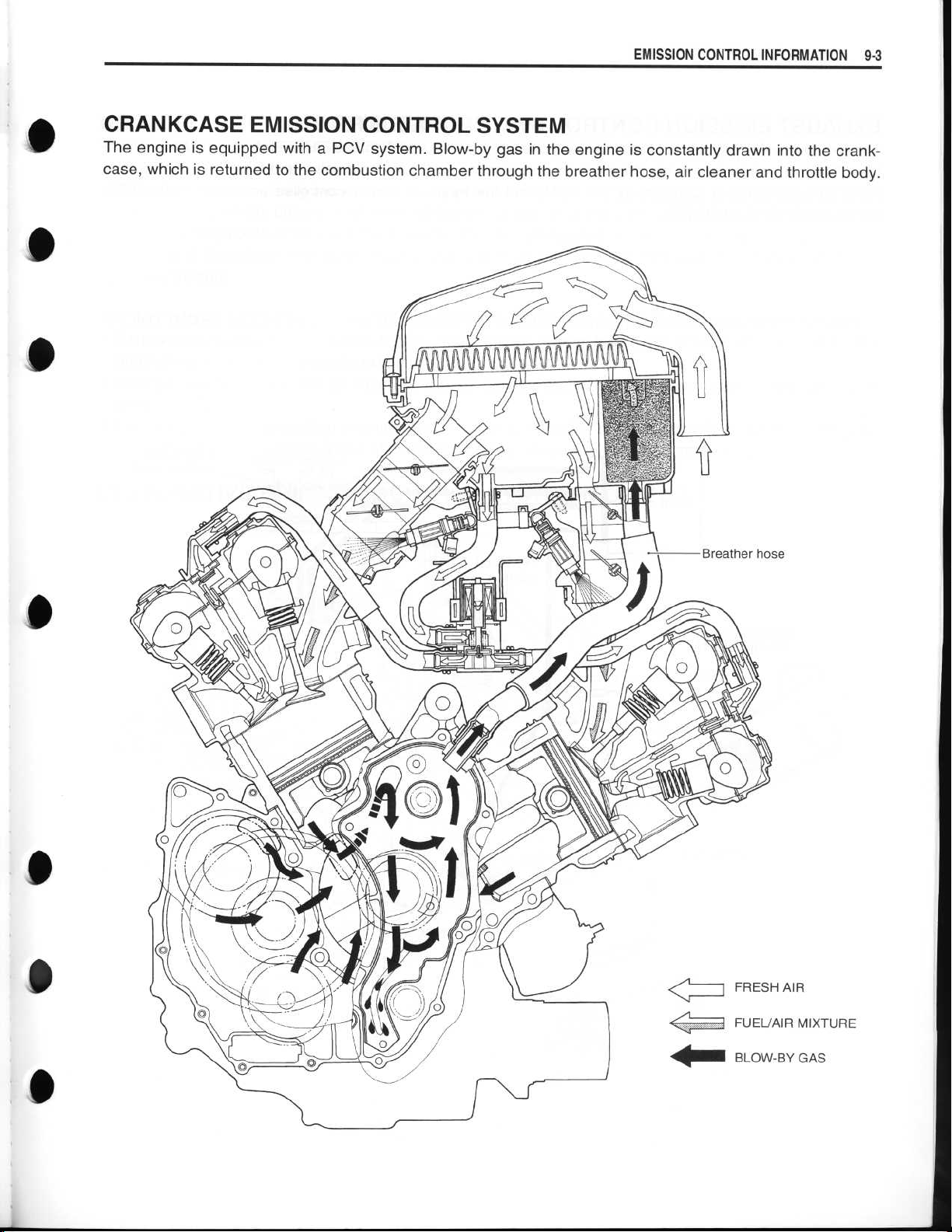
CRANKCASE EMISSION CONTROL SYSTEM
The engine is equipped with a PCV system
case, which is returned to the combustion chamber through the breather hose, air cleaner and throttle body
. Blow-by gas in the engine is constantly drawn into the crank-
.
0
0
0
C
411111110
FRESH AIR
FUEL/AIR MIXTURE
BLOW-BY GAS
Page 4
9-4 EMISSION CONTROL INFORMATION
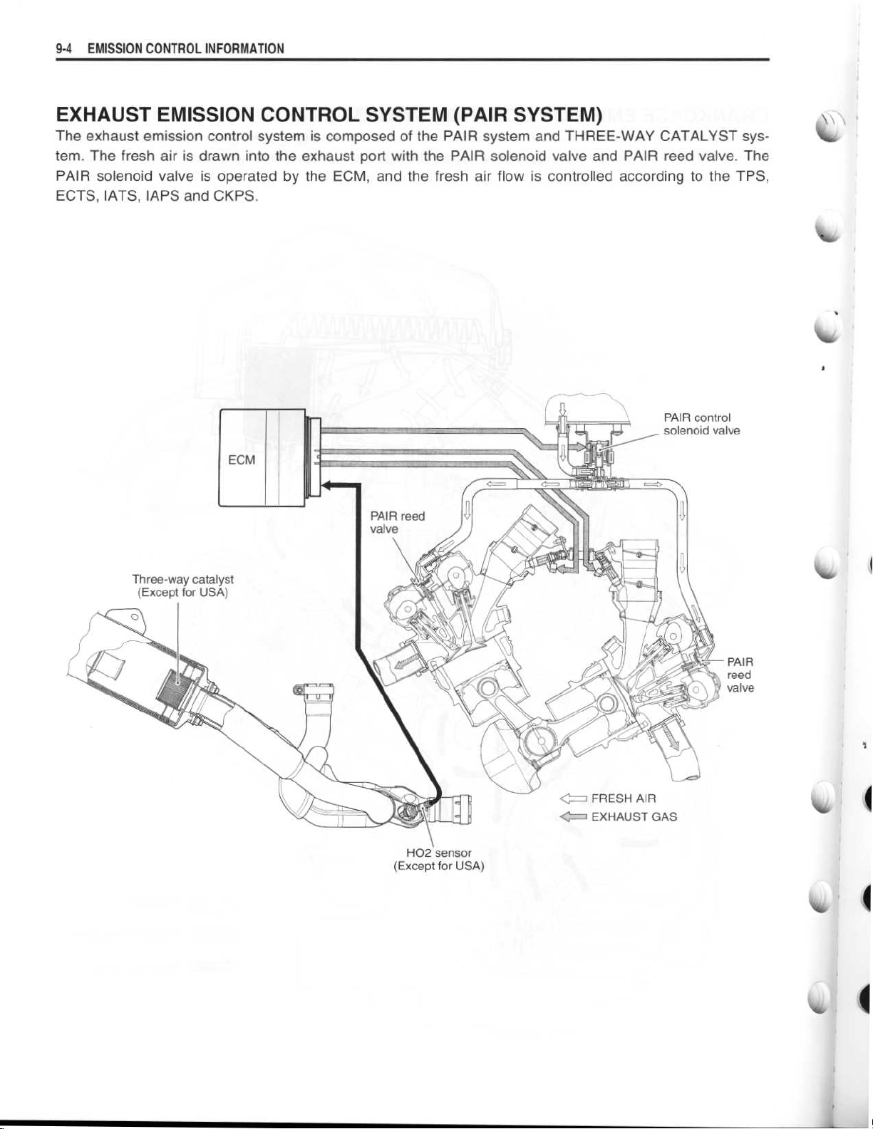
EXHAUST EMISSION CONTROL SYSTEM (PAIR SYSTEM)
The exhaust emission control system is composed of the PAIR system and THREE-WAY CATALYST sys-
tem
. The fresh air is drawn into the exhaust port with the PAIR solenoid valve and PAIR reed valve
PAIR solenoid valve is operated by the ECM, and the fresh air flow is controlled according to the TPS,
ECTS, IATS, ZAPS and CKPS
.
. The
H02 sensor
(Except for USA)
I
Page 5
~
~
~
EMISSION CONTROL INFORMATION 9-5
NOISE EMISSION CONTROL SYSTEM
0
0
TAMPERING WITH THE NOISE CONTROL SYSTEM PROHIBITED
acts or the causing thereof
1
. The removal or rendering inoperative by any person, other than for purposes of maintenance, repair or
replacement, of any device or element of design incorporated into any new vehicle for the purpose of
noise control prior to its sale or delivery to the ultimate purchaser or while it is in use, or
2
. The use of the vehicle after such device or element of design has been removed or rendered inoperative
by any person
.
:
: Federal law prohibits the following
0
0
AMONG THOSE ACTS PRESUMED TO CONSTITUTE TAMPERING ARE THE ACTS LISTED BELOW
Removing or puncturing the muffler, baffles, header pipes, screen type spark arrester (if equipped) or any
•
other component which conducts exhaust gases
•
Removing or puncturing the air cleaner case, air cleaner cover, baffles or any other component which
conducts intake air
•
Replacing the exhaust system or muffler with a system or muffler not marked with the same model spe-
cific code as the code listed on the Motorcycle Noise Emission Control Information label
.
.
.
:
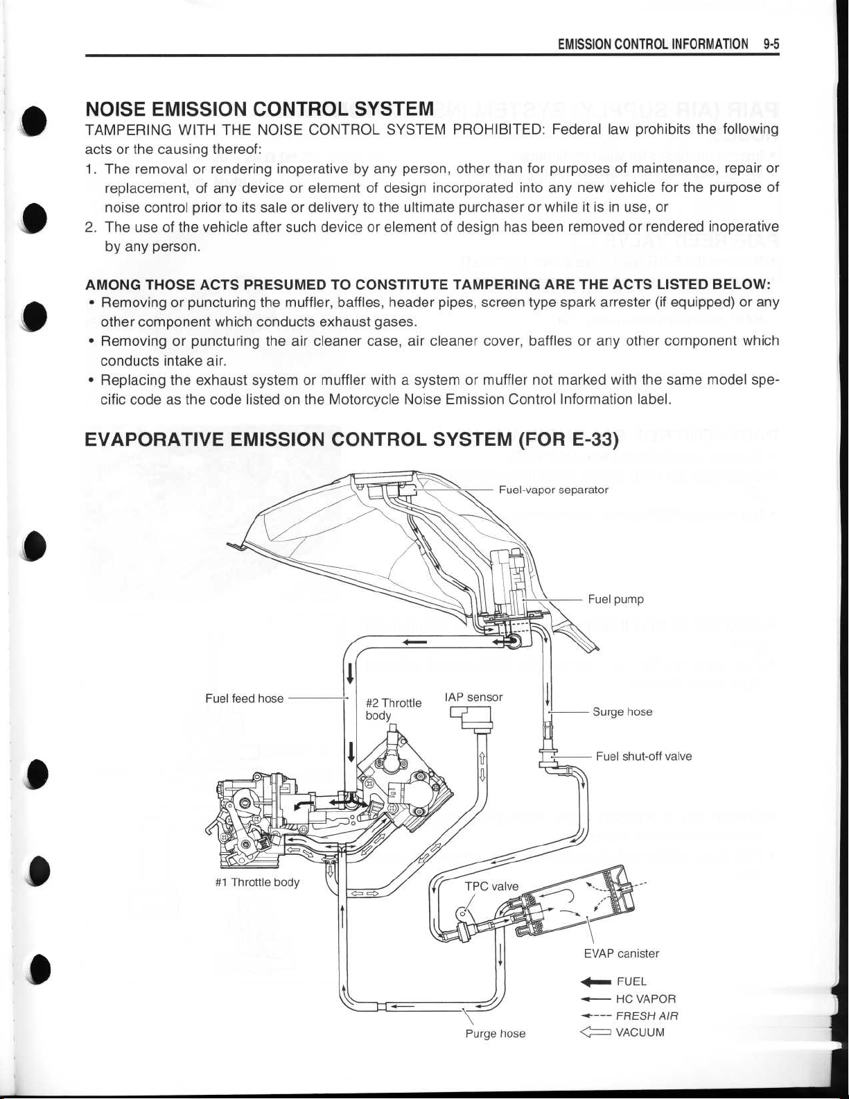
EVAPORATIVE EMISSION CONTROL SYSTEM (FOR E-33)
0
#1 Throttle body
EVAP canister
FUEL
1~
<- HC VAPOR
----
FRESH AIR
< f
VACUUM
Page 6

~
~
~
~
~
~
~
~
~
~
~
~
9-6 EMISSION CONTROL INFORMATION
PAIR (AIR SUPPLY) SYSTEM INSPECTION
HOSES
•
Inspect the hoses for wear or damage
•
Inspect that the hoses are securely connected
PAIR REED VALVE
•
Remove the PAIR reed valve cover
•
Inspect the reed valve for the carbon deposit
If the carbon deposit is found in the reed valve, replace the
•
PAIR reed valve with a new one
.
.
. (=3-34)
.
.
PAIR CONTROL SOLENOID VALVE
Remove the air cleaner box
•
Disconnect the PAIR control solenoid valve lead wire coupler
•
10
.
Remove the PAIR control solenoid valve
•
Check that air flows through the air inlet port to the air outlet
•
ports
.
If air does not flow out, replace the PAIR control solenoid
•
valve with a new one
•
Connect the 12 V battery to the PAIR control solenoid valve
terminals and check the air flow
•
If air does not flow out, the solenoid valve is in normal condition
.
.(f-74-75)
(Z
.
.
.
No
I
Page 7

~
EMISSION CONTROL INFORMATION 9-7
•
Check the resistance between the terminals of the PAIR con-
9
trol solenoid valve
.
0
0
0
Resistance
09900-25008
~gy Tester knob indication
If the resistance is not within the standard range, replace the
PAIR control solenoid valve with a new one
: 20-24 S (at 20 °C/68 °F)
: Multi circuit tester set
: Resistance (S2)
.
0
Page 8

~
9-8EMISSION
CONTROL INFORMATION
PAIR (AIR SUPPLY) SYSTEM HOSE ROUTING
Matching mark
(White)
I II
11
.Mm
4V
'
10 N•m1
0
MI
Matching mark
(Yellow)
.0 kgf-m, 7
.0 lb-ft)
1
%
4
4
4
PAIR read valve
qu
4
Page 9

~
~
~
0
0
EMISSION CONTROL INFORMATION 9-9
H EATED OXGEN SENSOR (HO2S) INSPECTION (FOR E-02, 19)
•
Disconnect the H02 sensor lead wire coupler
•
Inspect the H02 sensor and its circuit referring to flow table of
the malfunction code (C44)
.
. (=4-61)
J
I
•
Check the resistance between the terminals of the H02 sensor
.
Resistance
.
.
09900-25008
Tester knob indication
0
If the resistance is not within the standard range, replace the
H02 sensor with a new one
NOTE
:
* Temperature of the sensor affects resistance value largely
* Make sure that the sensor heater is at correct temperature
A WARNING
Do not remove the H02 sensor while it is hot
CAUTION
Be careful not to expose it to excessive shock
Do not use an impact wrench while removing or
installing the H02 sensor unit
Be careful not to twist or damage the sensor lead wire
: 4-5 S2 (at 23 °C/73
: Multi circuit tester set
: Resistance (0)
.
.4 °F)
.
.
.
.
.
.
0
0
0
Page 10

~
~
~
~
9-10
EMISSION CONTROL INFORMATION
EVAPORATIVE EMISSION CONTROL SYSTEM INSPECTION
(FOR E-33)
•
Remove the air cleaner box.((-
HOSES
Inspect the hoses for wear or damage
Make sure that the hoses are securely connected
EVAP CANISTER
Inspect the canister for damage to the body
TANK PRESSURE CONTROL VALVE
Inspect the tank pressure contorol valve body for damage
Inspect the tank pressure control valve operation in the following
procedure
.
r4-75)
.
VA
.
.
Vol,'
.
I
0
•
Remove the tank pressure control valve
•
When air pressure is applied to the tank pressure control
valve from the side
control valve
•
When air pressure is applied to the tank pressure control
valve from the side ©, air should not flow through the purge
valve
.
•
If the tank pressure control valve operates otherwise, it must
be replaced
A WARNING
Gasoline and gasoline vapor is toxic
of fuel remains in the tank pressure control valve
when checking it
Do not swallow the fuel when blowing the tank pres-
sure control valve
NOTE
:
When connecting the tank pressure control valve to the hose,
the side © should face toward the fuel shut-off valve side, and
the side AO should face toward the canister side
.
.
air should flow out through the purge
OO
,
.
.
.
. A small amount
.
1
% 4
1
4,
Page 11

EMISSION CONTROL INFORMATION
9-11
•
EVAP CANISTER HOSE ROUTING (FOR E-33)
EVAP canister
Fuel shut-off valve
Clamp ends should face top side
Clamp ends should face outside
Tank pressure~~~
control valve
.
i
.
Page 12

~
~
~
WIRING DIAGRAM
FI SYSTEM WIRING DIAGRAM
0
0
0
is
ECM
© BATT
©FP
41 TOS
33 AT
a
+B
18 CLT
® IG1
© IG2
©VM
36 THW
© SOL
05 FI #1
Fl #2
21 STA
© MO+
©MO-
14 THA
10 VCC
19 TPS
34 E2
® STPS
© H02 (OXH)
24 H02 (OX)
(2
G+
31 GP
© N+
30 N-
3s TS
16 PM
© PA
® TACO
© TECH
40 NT
•
•
•
IGNITION COIL 30 A
IG2
-R/W
- Y/B
-Br/W
O/R
-
O/G
-
B/Y
-B
-W/BI-
-Y/R
-B/BI
-Br
-Gr/W
-
Gr/B
-
Y/G
-
B/R
-
R/B
-
Dg
--R
-P/W
-B/Br
-y-
-
W/B
-
W/G
-
Y/W
-
G/BI
- G
-W/R
-G/B
-G/Y
-
-
-
-B/W-
-B/W-
-B/W
MODE SELECTION SWITCH
Br/B
B/G
BI
-
IG1
15A
MAIN
SWITCH
10A
6'`p
10A
TIP OVER SENSOR
0
L
ATMOSPHERIC
PRESSURE
SENSOR
NEUTRAL
LAMP
SI
RE
FUE
4)
SPEEDOMETER
INTAKE AIR CONTROL VALVE
PRESSURE
SENSOR
PAIR SOLENOID
SIDESTAND
SWITCH
Page 13

~
~
~
RELA
RELAY
I
ENGINE STOP
Y
SWITCH
FUEL PUMP RELAY
GEAR CLUTCH
END
POSITION LEVER
ITCH SWITCH
POSITION
SWITCH
HO2SENSOR
(Except for USA)
FUEL INJECTOR
Fl
STPS SECONDARY THROTTLE POSITION SENSOR
ECTS ENGINE COOLANT TEMP SENSOR
TPS
THROTTLE POSITION SENSOR
TATS
INTAKE AIR TEMP SENSOR
CMPS
CAMSHAFT POSITION SENSOR
CKPS
CRANKSHAFT POSITION SENSOR
STVA SECONDARY THROTTLE VALVE ACTUATOR
10
Page 14

~
~
~
~
~
~
~
~
~
WIRING DIAGRAM
E-03, 24, 28, 33
R:TURN SIGNAL INDICATOR LIGHT (R)
L:TURN SIGNAL INDICATOR LIGHT (L)
B
: HI-BEAM INDICATOR LIGHT
N:NEUTRAL INDICATOR LIGHT
F:FUEL WARNNING LIGHT
O
: OIL PRESSURE, FI INDICATOR LIGHT
POSITION LIGHT (R)
B
Br-,1-Br
Bnv~env
FRONT TURN SIGNAL LIGHT (R)
Lg
Lg
B/W
B/W
HEADLIGHT (R)
HEADLIGHT (L)
FRONT TURN SIGNAL LIGHT (L)
a
POSITION LIGHT (L)
B
-/W~13111W
B/W
B/W
B/W
Y
W
Y
W
BB/W
,
B/W
Lg
W -
Br
Y -
B -
HANDLEBAR
HAZARD ENGINE
N
vi'
SPEEDOMETER
m m
~mm0
OmOammm~
-
-
Lg
Y
-
BIW
- W
-
IIL'
B
IGNITION SWITCH
~onom
mMMO
mu∎∎//
MESON
SWITCH SWITCH
m
~~ooo3>
Ell
SWITCH
STOP
STARTER FRONT BRAKE
SWITCH SWITCH
ICoT mCl
J
(R)
IL
PORE,'
swIT
m
m
m
03
u
mjJmom3mmm
J
~
HORN
IIIIIIIIII
O
O//
i~~ //
HORN
BUTTON TURN SIGNAL LIGHT
mCN
El
~C01-
0-11
SWITCH
HANDLEBAR SWITCH (L)
PASSING DIMM
SWITCH
DIMMER
SWITCH
OCR
LEVER
POSITION
SWITCH
o'o
mm
B/R
CTid//
FAN MOTOR FAN
SWITCH
m
0
00
MOTOR
mam
STP
SENSOR
I
ACTUATOR
MOTOR
mm¢m
mmi/j
m¢¢m
m i
¢
~y
#2 #1
INJECTOR
m` mm5oL~~
O
IAP
SENSOR
R(
Ofm
CENSO
R
mm`
mm
ECT
SENS(
Page 15

~
~
~
~
~
~
~
~
~
~
IRE
FUEL
PUMP
¢gym
:~i2
REAR BRAKE
SWITCH
MEN
M//
mm
of
FUEL PUMP
RELAY
ffm
m0=>
SENSOR
m
mm
AP
SENSOR
0
m ¢
~IIIIIII
mm
~m~m
;mm0O
IIIillllllllll
m
~¢m~~>o~B?z5
¢
m>m
Oc~mmam>3
ECM
IIIIIIIIIIIIIIIIIIII
C3B~>mms?Oam¢m`>LmQ~¢m~~¢>
mi3m>r
>ommmmm3
mmm
(
III II
m~mr~¢Z
mmmmmm
~~
¢ ¢
0 3
10
¢~
Cm
m¢m
GEAR
POSITION
SWITCH
Br
B/W
REAR TURN SIG NAL LIGHT (R)
Lg
B/W
Br
B/W
B
REAR TURN SIGN
O
mm
0OO
>
R-1
FUSE BOX
m
om
F
1
. HEAD HI 15 A
2
. HEAD LO 15 A
3
. FUEL
4
. IGNITION 15 A
5
. SIGNAL
6
. FAN~15A
10 A
10A
PAIR
SORENOID
SENSOR
m
SPEEDOMETER
SENSOR
¢
0
SIDE STAND
SWITCH
GENERATOR
-RECTIFIER
RECTIFIER
STARTER 1
MOTOR
Z- S2 Q~ q~
m
>mm
: MAIN 30 A
STARTER
RELAY
BATTERY
LIC ENSE LIGHT
B
B
B
B/W
10
BRAKE LIG HTITAILLIGHT
Gr
0
B/W
W/BW/B
B
I
ji
B/W
AL LIGHT (L)
V-
Page 16

0
Prepared by
SUZUKI MOTOR CORPORATION
0
0
February, 2003
Part No
. 99500-39250-03E
Printed in Japan
476
Page 17

SUZUKI MOTOR CORPORATION
Printed in Japan ~TK
;
K3
 Loading...