

Page 1

IMPORTANT
WARNING /CAUTION/ NOTE
Please read this manual and follow its instructions
carefully. To emphasize special information, the
words WARNING, CAUTION and NOTE have special meanings. Pay special attention to the messages
highlighted by these signal words.
NOTE:
Indicates special information to make maintenance easier or instructions clearer.
WARNING:
Indicates a potential hazard that could result
in death or injury.
CAUTION:
Indicates a potential hazard that could result
in vehicle damage.
WARNING:
This service manual is intended for authorized
SUZUKI dealers and qualified service mechanics only. Inexperienced mechanics or
mechanics without the proper tools and
equipment may not be able to properly perform the services described in this manual.
Improper repair may result in injury to the mechanic and may render the vehicle unsafe for
the driver and passengers.
Page 2

()
x
()
x
()
x
()
x
()
x
()
x
()
x
()
x
()
x
()
x
()
x
()
x
()
x
()
x
()
x
()
x
()
x
()
x
FOREWORD
This SUPPLEMENTARY SERVICE MANUAL is a supplement to SF SERIES SERVICE MANUALS mentioned in next page and has been prepared exclusively for the following applicable model.
Applicable model: SF310/SF413 of and after the vehicle identification numbers below.
Vehicle Identification Number (Vehicle Specification)
TSMMAA44S00600001 (SF310 3 door H/B 2WD)
TSMMAB44S00600001 (SF310 5 door H/B 2WD)
TSMMAA35S00600001 (SF413 3 door H/B 2WD)
TSMMAB35S00600001 (SF413 5 door H/B 2WD)
TSMMAB35S10600001 (SF413 5 door H/B 2WD)
TSMMSF35S00600001 (SF413 3 door H/B 4WD)
TSMMSG35S00600001 (SF413 5 door H/B 4WD)
TSMMAH35S00600001 (SF413 4 door N/B 2WD)
TSMMAH35S10600001 (SF413 4 door N/B 2WD)
When servicing the above applicable models, refer to this SUPPLEMENTARY SERVICE MANUAL first. If necessary information is not found in this SUPPLEMENTARY SERVICE MANUAL, refer to RELATED MANUALS specified next page.
All information, illustrations and specifications contained in this literature are based on the latest
product information available at the time of publication approval. And used as the main subject
of description is the vehicle of standard specifications among others. Therefore, note that illustrations may differ from the vehicle being actually serviced.
The right is reserved to make changes at any time without notice.
OVERSEAS SERVICE DEPARTMENT
COPYRIGHT SUZUKI MOTOR CORPORATION 2000
Page 3

RELATED MANUALS
Related manuals listed below are in the chronological order with the latest one at the top. For the efficient use of
manuals, start with one at the top of the list (i.e., the latest one). If desired section, item or description is not found
in it, try next one in the list and do the same one by one till what is being searched is found.
MODEL
NO. RELATED SERVICE MANUAL APPLICABILITY
SF310/
SF413
1
SF310/SF413
WIRING DIAGRAM MANUAL
(99512-80E10-019)
This manual is prepared exclusively for the applicable model mentioned in FOREWORD of this
supplementary service manual.
SF
SERIES
1
SF SERIES SUPPLEMENTARY
SERVICE MANUAL
(99501-80E00-xxx)
This manual describes the updated information
from the SF310 and SF413 Service Manuals
below.
SF310
1
SF310 SUPPLEMENTARY
SERVICE MANUAL
(99501-60B00-xxx)
This manual describes the items that are updated
(modified and added) from the Service Manual
(99500-60B01).
(1,000 cc)
2
SF310 SERVICE MANUAL
(99500-60B01-xxx)
This manual is the base manual for the above
manual.
1
SF413 SUPPLEMENTARY
SERVICE MANUAL
(99501-63B30-xxx)
[Pub. No. G4203GE]
This manual describes the items that are updated
(modified and added) from the Service Manual
(99500-63B01).
SF413
(1,300 cc)
2
SF413 SUPPLEMENTARY
SERVICE MANUAL
(99501-63B20-xxx)
[Pub. No. G4202GE]
This manual describes the items for 4WD model
that are updated (modified and added) from the
Service Manual (99500-63B01).
(, )
2
SF413 SUPPLEMENTARY
SERVICE MANUAL
(99501-63B10-xxx)
This manual describes the items for SEDAN model that are updated (modified and added) from the
Service Manual (99500-63B01).
3
SF413 SERVICE MANUAL
(99500-63B01-xxx)
[Pub. No. G4200GE]
This manual is the base manual for the above
manuals.
SF
SERIES
(A/C)
1
AIR CONDITIONING BASIC
MANUAL (99520-02130-xxx)
This manual is the base manual of A/C system.
Page 4

6
6
6-1
6A
6A1
6B
6C
6E1
6E1
6E2
6F
6F
6F1
6G
6H
6K
GENERAL INFORMATION
General Information
Maintenance and Lubrication
1A
1B
TABLE OF CONTENTS SECTION
0A
0B
7B
8
8A
8G
HEATING AND AIR CONDITIONING
Heater and Ventilation
Air Conditioning (Oprional)
ENGINE
General Information and Diagnosis
(TBI for G10)
General Information and Diagnosis
(TBI for G13)
General lnformation and Diagnosis
(SFI for G13)
Engine Mechanical (G10 Engine)
Engine Mechanical
(G13 1-cam 16-valves Engine)
Engine Cooling
Engine Fuel
Engine and Emission Control System
(TBI for G10)
Engine and Emission Control System
(TBI for G13)
Engine and Emission Control System
(SFI for G13)
Ignition System (TBI for G10)
Ignition System (TBI for G13)
Ignition System (SFI for G13)
Cranking System
Charging System
Exhaust System
TRANSMISSION, CLUTCH AND
DIFFERENTIAL
Automatic Transmission
BODY ELECTRICAL SYSTEM
Wiring Diagram
IMMOBILIZER CONTROL SYSTEM
1B
0B
0A
1A
6
6B
6C
6E1
6A1
6F
6G
6H
6K
7B
8
8A
8G
6-1
6A
6E2
6F1
6
6E1
6F
NOTE:
The screen toned Section 8A is contained in WIRING DIAGRAM MANUAL mentioned in
RELATED MANUALS.
Page 5

GENERAL INFORMATION 0A-1
0A
SECTION 0A
GENERAL INFORMATION
CONTENTS
HOW TO USE THIS MANUAL 0A- 2. . . . . . . . . . . . . . . . . . . . . . . . . . . . . . . . . . . . . . . . . . . . . . . . . . . . . . . . . . . . . . .
PRECAUTIONS 0A- 3. . . . . . . . . . . . . . . . . . . . . . . . . . . . . . . . . . . . . . . . . . . . . . . . . . . . . . . . . . . . . . . . . . . . . . . . . . . .
Precaution for Vehicles Equipped with a Supplemental Restraint (Air Bag) System 0A- 3. . . . . . . . . . . . . . . .
General Precautions 0A- 6. . . . . . . . . . . . . . . . . . . . . . . . . . . . . . . . . . . . . . . . . . . . . . . . . . . . . . . . . . . . . . . . . . . . . .
Precautions for Catalytic Converter 0A- 9. . . . . . . . . . . . . . . . . . . . . . . . . . . . . . . . . . . . . . . . . . . . . . . . . . . . . . . . .
Precautions for Electrical Circuit Service 0A- 9. . . . . . . . . . . . . . . . . . . . . . . . . . . . . . . . . . . . . . . . . . . . . . . . . . . . .
Electrical Circuit Inspection Procedure 0A-12. . . . . . . . . . . . . . . . . . . . . . . . . . . . . . . . . . . . . . . . . . . . . . . . . . . . . .
Intermittent and Poor Connection 0A-15. . . . . . . . . . . . . . . . . . . . . . . . . . . . . . . . . . . . . . . . . . . . . . . . . . . . . . . . . . .
Precaution for Installing Mobile Communication Equipment 0A-16. . . . . . . . . . . . . . . . . . . . . . . . . . . . . . . . . . . .
Precaution in Servicing Full-Time 4WD Vehicle 0A-17. . . . . . . . . . . . . . . . . . . . . . . . . . . . . . . . . . . . . . . . . . . . . . .
IDENTIFICATION INFORMATION 0A-18. . . . . . . . . . . . . . . . . . . . . . . . . . . . . . . . . . . . . . . . . . . . . . . . . . . . . . . . . . . .
Vehicle Identification Number 0A-18. . . . . . . . . . . . . . . . . . . . . . . . . . . . . . . . . . . . . . . . . . . . . . . . . . . . . . . . . . . . . .
Identification Whether Vehicle Equipped with WU-TWC or Not 0A-18. . . . . . . . . . . . . . . . . . . . . . . . . . . . . . . . . .
Engine Identification Number 0A-18. . . . . . . . . . . . . . . . . . . . . . . . . . . . . . . . . . . . . . . . . . . . . . . . . . . . . . . . . . . . . . .
Transmission Identification Number 0A-18. . . . . . . . . . . . . . . . . . . . . . . . . . . . . . . . . . . . . . . . . . . . . . . . . . . . . . . . .
WARNING, CAUTION AND INFORMATION LABELS 0A-19. . . . . . . . . . . . . . . . . . . . . . . . . . . . . . . . . . . . . . . . . .
VEHICLE LIFTING POINTS 0A-20. . . . . . . . . . . . . . . . . . . . . . . . . . . . . . . . . . . . . . . . . . . . . . . . . . . . . . . . . . . . . . . . .
ABBREVIATIONS AND SYMBOLS MAY BE USED IN THIS MANUAL 0A-22. . . . . . . . . . . . . . . . . . . . . . . . . . .
FASTENER INFORMATION 0A-25. . . . . . . . . . . . . . . . . . . . . . . . . . . . . . . . . . . . . . . . . . . . . . . . . . . . . . . . . . . . . . . . .
Metric Fasteners 0A-25. . . . . . . . . . . . . . . . . . . . . . . . . . . . . . . . . . . . . . . . . . . . . . . . . . . . . . . . . . . . . . . . . . . . . . . . .
Fasteners Strength Identification 0A-25. . . . . . . . . . . . . . . . . . . . . . . . . . . . . . . . . . . . . . . . . . . . . . . . . . . . . . . . . . .
Standard Tightening Torque 0A-26. . . . . . . . . . . . . . . . . . . . . . . . . . . . . . . . . . . . . . . . . . . . . . . . . . . . . . . . . . . . . . . .
Page 6
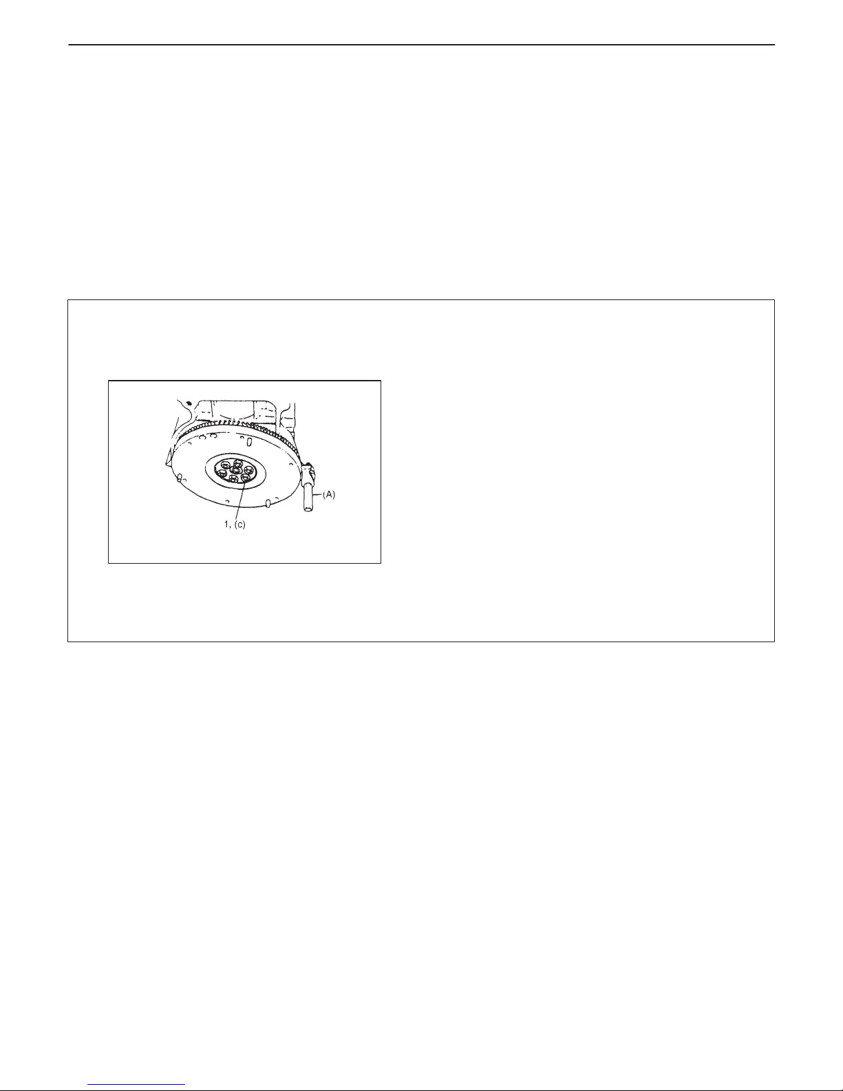
1. Flywheel bolts or drive plate bolts for A / T vehicle
6) Install oil pump. Refer to “Oil pump”.
7) Install flywheel (for M/T vehicle) or drive plate
(for A/ T vehicle).
Using special tool, lock flywheel or drive plate, and
tighten flywheel or drive plate bolts to specified
torque.
Special Tool
(A): 09924-17810
Tightening Torque
(c): 78 N
.
m (7.8 kg-m, 56.0 lb-ft)
0A-2 GENERAL INFORMATION
HOW TO USE THIS MANUAL
1) There is a TABLE OF CONTENTS FOR THE WHOLE MANUAL
on the third page of this manual, whereby you can easily find the
section that offers the information you need. Also, there is a
CONTENTS on the first page of EACH SECTION, where the
main items in that section are listed.
2) Each section of this manual has its own pagination. It is indicated
at the top of each page along with the Section name.
3) The SPECIAL TOOL usage and TIGHTENING TORQUE
SPECIFICATION are given as shown in figure below.
4) A number of abbreviations are used in the text.
For their full explanations, refer to “ABBREVIATIONS AND
SYMBOLS MAY BE USED IN THIS MANUAL” of this section.
5) The SI, metric and foot-pound systems are used as units in this
manual.
6) DIAGNOSIS are included in each section as necessary.
7) At the end of each section, there are descriptions of SPECIAL
TOOLS, REQUIRED SERVICE MATERIALS and TIGHTENING TORQUE SPECIFICATIONS that should be used for the
servicing work described in that section.
Page 7
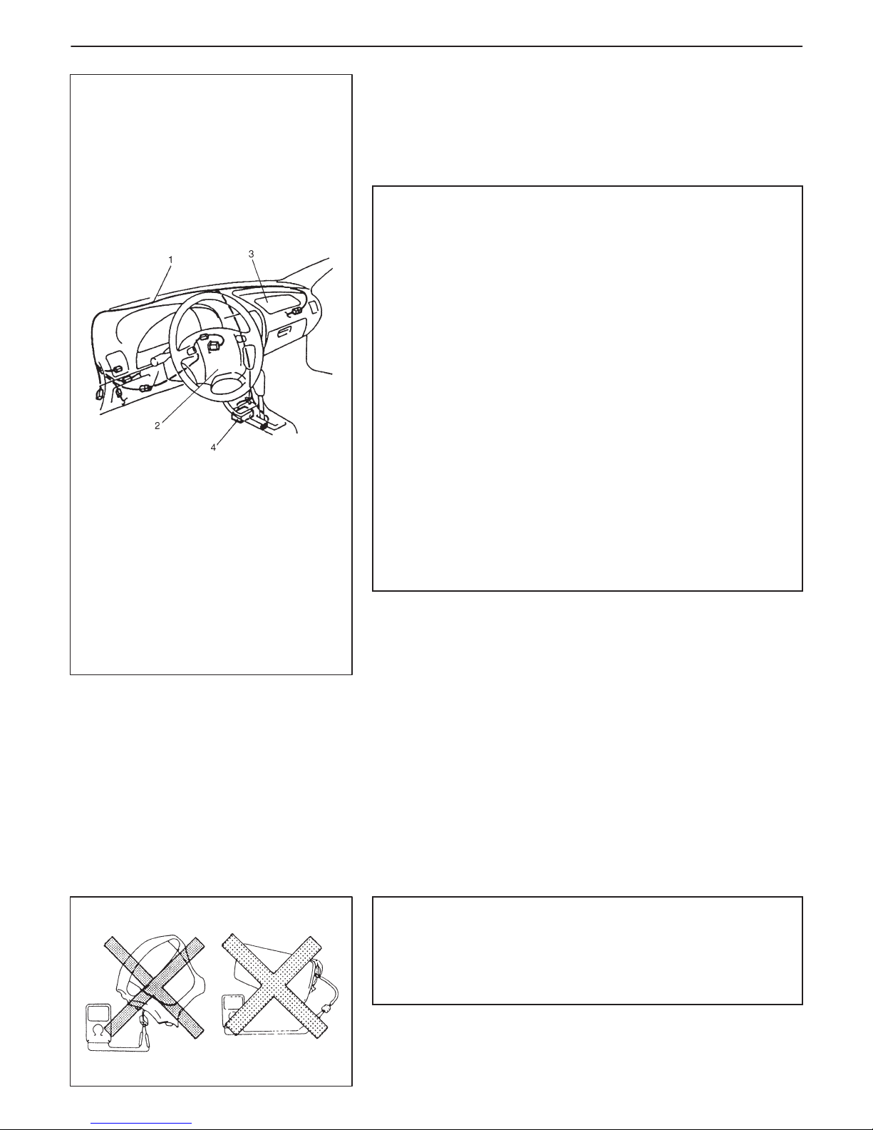
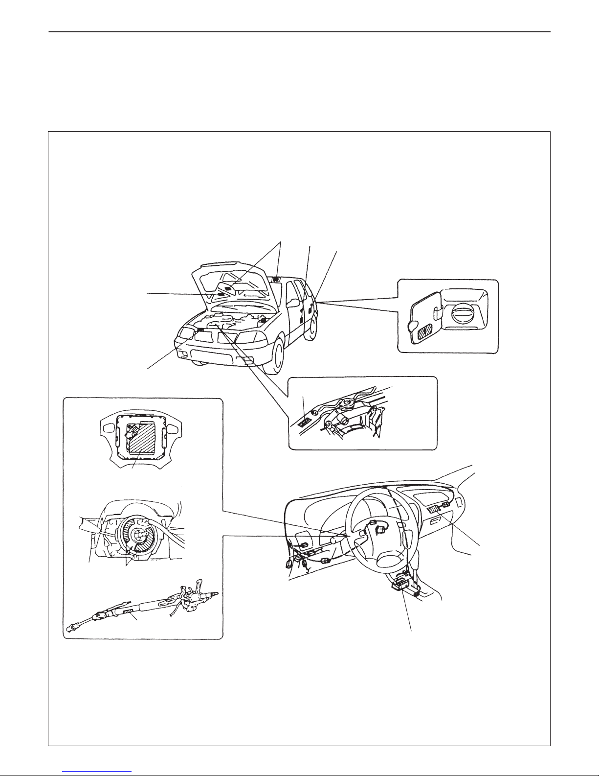
1. Air bag wire harness
2. Driver air bag (inflator) module
3. Passenger air bag (inflator) module
4. SDM
GENERAL INFORMATION 0A-3
PRECAUTIONS
PRECAUTION FOR VEHICLES EQUIPPED
WITH A SUPPLEMENTAL RESTRAINT (AIR
BAG) SYSTEM
WARNING:
D The configuration of air bag system parts are as shown in
the figure. When it is necessary to service (remove, reinstall and inspect) these parts, be sure to follow procedures described in Section 9J. Failure to follow proper
procedures could result in possible air bag deployment,
personal injury, damage to parts or air bag being unable
to deploy when necessary.
D If the air bag system and another vehicle system both
need repair, Suzuki recommends that the air bag system
be repaired first, to help avoid unintended air bag deployment.
D Do not modify the steering wheel, dashboard, or any other
air bag system component. Modifications can adversely
affect air bag system performance and lead to injury.
D If the vehicle will be exposed to temperatures over 93_C,
200_F (for example, during a paint baking process), remove the air bag system components (air bag (inflator)
modules, sensing and diagnostic module) beforehand to
avoid component damage or unintended deployment.
DIAGNOSIS
D When troubleshooting air bag system, be sure to follow
“DIAGNOSIS” in Section 9J. Bypassing these procedures
may result in extended diagnostic time, incorrect diagnosis,
and incorrect parts replacement.
D Never use electrical test equipment other than that specified
in this manual.
WARNING:
Never attempt to measure the resistance of the air bag (inflator) modules (driver and passenger). It is very dangerous
as the electric current from the tester may deploy the air
bag.
Page 8
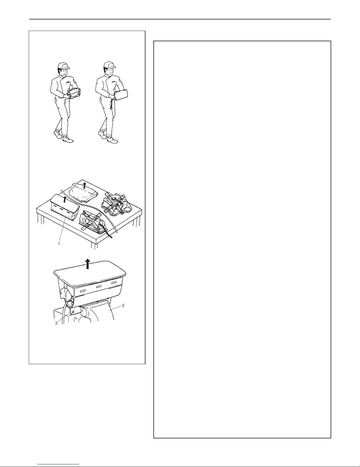
1. Slit on workbench
2. Workbench vise
3. Lower mounting bracket
ALWAYS CARRY AIR BAG (INFLATOR) MODULE
WITH TRIM COVER (AIR BAG OPENING) AWAY
FROM BODY.
ALWAYS PLACE AIR BAG (INFLATOR) MODULE
ON WORKBENCH WITH TRIM COVER (AIR BAG
OPENING) UP, AWAY FROM LOOSE OBJECTS.
0A-4 GENERAL INFORMATION
HANDLING AND SERVICING
WARNING:
D Many of service procedures require disconnection of
“AIR BAG” fuse and air bag (inflator) modules (driver and
passenger) from deployment loop to avoid an accidental
deployment.
Driver and Passenger Air Bag (Inflator) Modules
D For handling and storage of a live air bag (inflator) module,
select a place where the ambient temperature below 65_C
(150_F), without high humidity and away from electric
noise.
D When carrying a live air bag (inflator) module, make sure
the bag opening is pointed away from you. In case of an
accidental deployment, the bag will then deploy with minimal chance of injury. Never carry the air bag (inflator)
module by the wires or connector on the underside of the
module. When placing a live air bag (inflator) module on
a bench or other surface, always face the bag up, away
from the surface. As the live passenger air bag (inflator)
module must be placed with its bag (trim cover) facing up,
place it on the workbench with a slit or use the workbench
vise to hold it securely at its lower mounting bracket. This
is necessary so that a free space is provided to allow the
air bag to expand in the unlikely event of accidental deployment. Otherwise, personal injury may result.
D Never dispose of live (undeployed) air bag (inflator) mod-
ules (driver and passenger). If disposal is necessary, be
sure to deploy them according to deployment procedures
described in Section 9J before disposal.
D The air bag (inflator) module immediately after deploy-
ment is very hot. Wait for at least half an hour to cool it off
before proceeding the work.
D After an air bag (inflator) module has been deployed, the
surface of the air bag may contain a powdery residue.
This powder consists primarily of cornstarch (used to lubricate the bag as it inflates) and by-products of the chemical reaction. As with many service procedures, gloves
and safety glasses should be worn.
SDM
D During service procedures, be very careful when handling
a Sensing and Diagnostic Module (SDM). Never strike or
jar the SDM. Never power up the air bag system when the
SDM is not rigidly attached to the vehicle. All SDM and
mounting bracket fasteners must be carefully torqued
and the arrow must be pointing toward the front of the vehicle to ensure proper operation of the air bag system. The
SDM could be activated when powered while not rigidly attached to the vehicle which could cause deployment and
result in personal injury.
Page 9

GENERAL INFORMATION 0A-5
CAUTION:
D Even when the accident was light enough not to cause air
bags to deploy, be sure to inspect system parts and other
related parts according to instructions under “Repair and
Inspection Required after an Accident” in Section 9J.
D When servicing parts other than air bag system, if shocks
may be applied to air bag system component parts, remove those parts beforehand.
D When handling the air bag (inflator) modules (driver and
passenger) or SDM, be careful not to drop it or apply an impact to it. If an excessive impact was applied (e.g.,
dropped from a height of 91.4 cm (3 feet) or more), never
attempt disassembly or repair but replace it with a new
one.
D When grease, cleaning agent, oil, water, etc. has got onto
air bag (inflator) modules (driver and passenger), wipe off
immediately with a dry cloth.
D Air bag wire harness can be identified easily as it is cov-
ered with a yellow protection tube. Be very careful when
handling it.
D When an open in air bag wire harness, damaged wire har-
ness, connector or terminal is found, replace wire harness, connectors and terminals as an assembly.
D Do not apply power to the air bag system unless all com-
ponents are connected or a diagnostic chart requests it,
as this will set a diagnostic trouble code.
D Never use air bag system component parts from another
vehicle.
D When using electric welding, be sure to temporarily dis-
able air bag system referring to “Disabling Air Bag System” under “Service Precaution” in Section 9J.
D Never expose air bag system component parts directly to
hot air (drying or baking the vehicle after painting) or
flames.
D WARNING/CAUTION labels are attached on each part of
air bag system components. Be sure to follow the instructions.
D After vehicle is completely repaired, perform “Air Bag
Diagnostic System Check” described in “Diagnosis” in
Section 9J.
Page 10
0A-6 GENERAL INFORMATION
GENERAL PRECAUTIONS
The WARNING and CAUTION below describe some general precautions that you should observe when servicing
a vehicle. These general precautions apply to many of the service procedures described in this manual, and they
will not necessarily be repeated with each procedure to which they apply.
WARNING:
D Whenever raising a vehicle for service, be sure to follow the instructions under “VEHICLE LIFTING
POINTS” on SECTION 0A.
D When it is necessary to do service work with the engine running, make sure that the parking brake
is set fully and the transmission is in Neutral (for manual transmission vehicles) or Park (for automatic
transmission vehicles). Keep hands, hair, clothing, tools, etc. away from the fan and belts when the
engine is running.
D When it is necessary to run the engine indoors, make sure that the exhaust gas is forced outdoors.
D Do not perform service work in areas where combustible materials can come in contact with a hot
exhaust system. When working with toxic or flammable materials (such as gasoline and refrigerant),
make sure that the area you work in is well-ventilated.
D To avoid getting burned, keep away from hot metal parts such as the radiator, exhaust manifold, tail-
pipe, muffler, etc.
D New and used engine oil can be hazardous. Children and pets may be harmed by swallowing new or
used oil. Keep new and used oil and used engine oil filters away from children and pets.
Continuous contact with used engine oil has been found to cause [skin] cancer in laboratory animals.
Brief contact with used oil may irritate skin. To minimize your exposure to used engine oil, wear a
long-sleeve shirt and moisture-proof gloves (such as dish washing gloves) when changing engine
oil. If engine oil contacts your skin, wash thoroughly with soap and water. Launder any clothing or
rags if wet with oil, recycle or properly dispose of used oil and filters.
D Make sure the bonnet is fully closed and latched before driving. If it is not, it can fly up unexpectedly
during driving, obstructing your view and resulting in an accident.
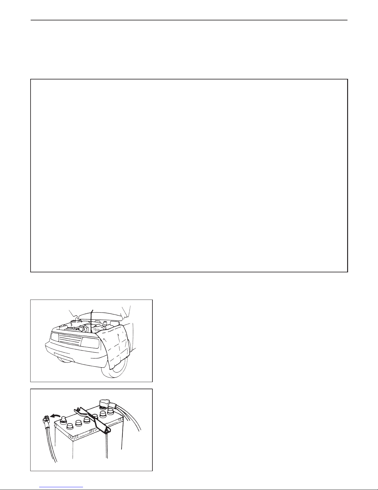
CAUTION:
D Before staring any service work, cover fenders, seats and
any other parts that are likely to get scratched or stained during servicing. Also, be aware that what you wear (e.g. buttons) may cause damage to the vehicle’s finish.
D When performing service to electrical parts that does not re-
quire use of battery power, disconnect the negative cable of
the battery.
Page 11
GENERAL INFORMATION 0A-7
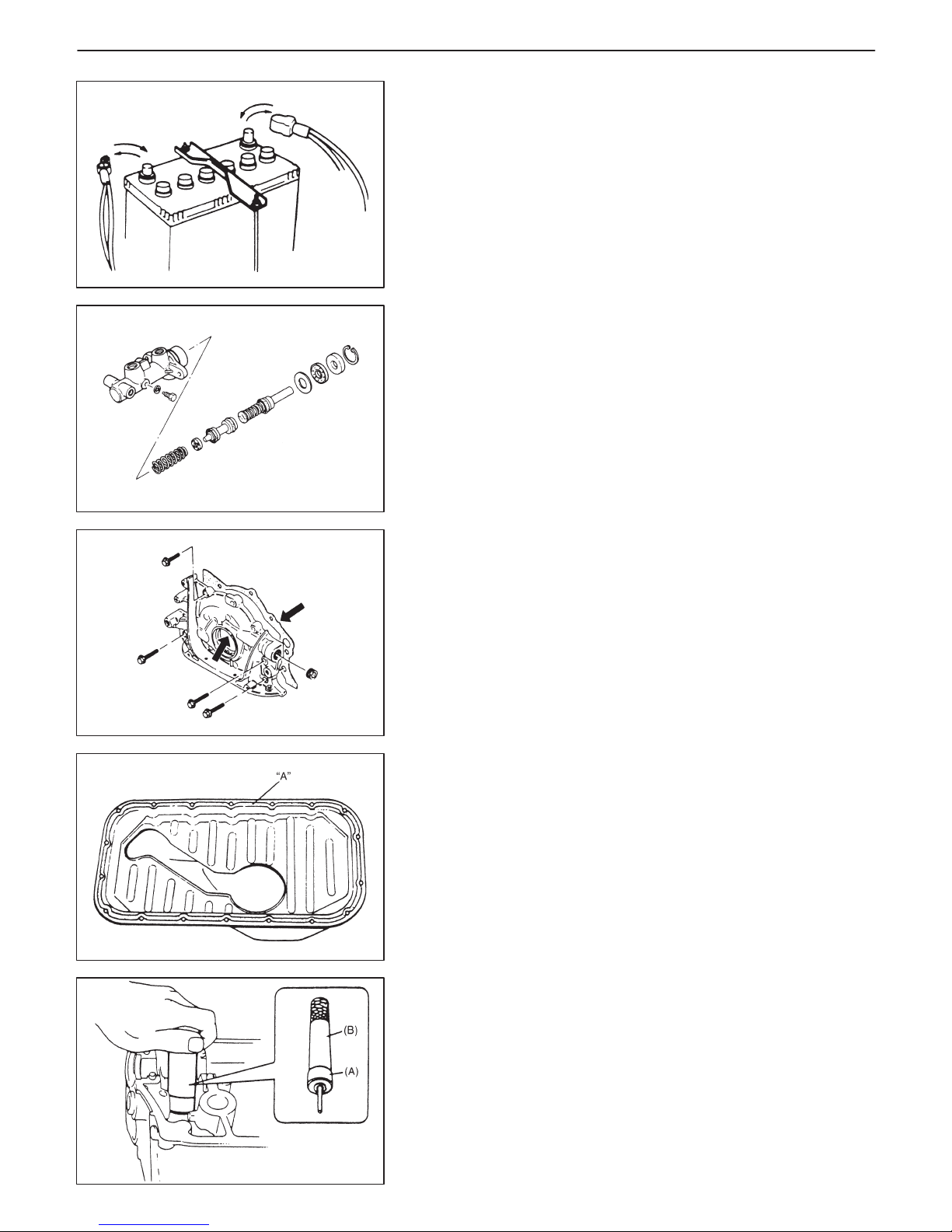
D When removing the battery, be sure to disconnect the nega-
tive cable first and then the positive cable. When reconnecting the battery, connect the positive cable first and then the
negative cable, and replace the terminal cover.
D When removing parts that are to be reused, be sure to keep
them arranged in an orderly manner so that they may be reinstalled in the proper order and position.
D Whenever you use oil seals, gaskets, packing, O-rings, lock-
ing washers, split pins, self-locking nuts, and certain other
parts as specified, be sure to use new ones. Also, before
installing new gaskets, packing, etc., be sure to remove any
residual material from the mating surfaces.
D Make sure that all parts used in reassembly are perfectly
clean.
D When use of a certain type of lubricant, bond or sealant is
specified, be sure to use the specified type.
“A”: Sealant 99000-31150
D Be sure to use special tools when instructed.
Special Tool
(A): 09917-98221
(B): 09916-58210
Page 12
0A-8 GENERAL INFORMATION
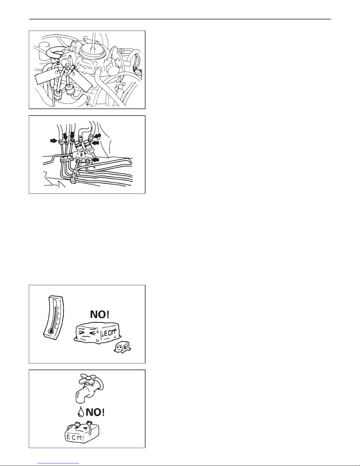
D When disconnecting vacuum hoses, attach a tag describing
the correct installation positions so that the hoses can be reinstalled correctly.
D After servicing fuel, oil, coolant, vacuum, exhaust or brake
systems, check all lines related to the system for leaks.
D For vehicles equipped with fuel injection systems, never dis-
connect the fuel line between the fuel pump and injector
without first releasing the fuel pressure, or fuel can be
sprayed out under pressure.
D When performing a work that produces a heat exceeding
80_C in the vicinity of the electrical parts, remove the heat
sensitive electrical part(s) beforehand.
D Use care not to expose connectors and electrical parts to wa-
ter which will be a cause of a trouble.
Page 13
GENERAL INFORMATION 0A-9
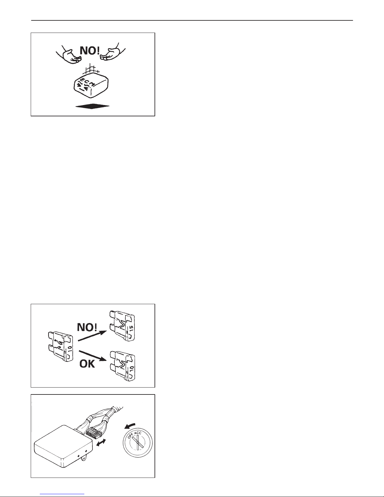
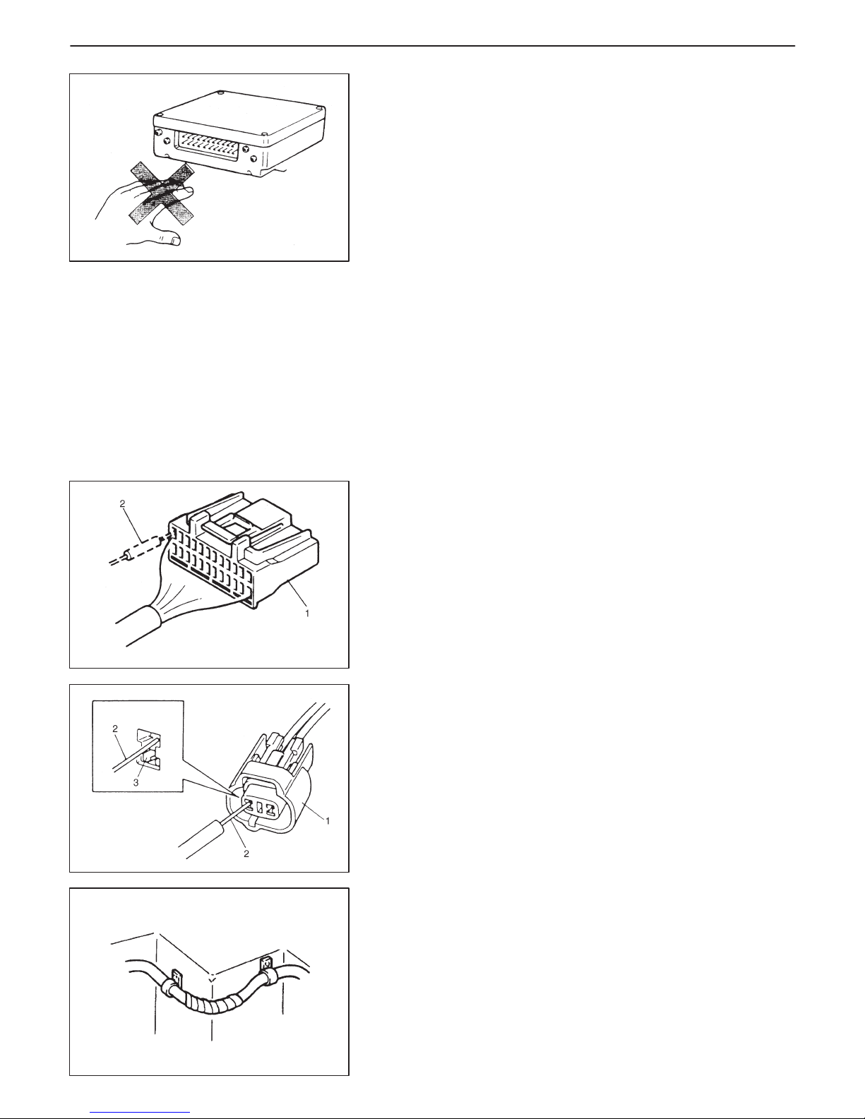
D Always be careful not to handle electrical parts (computer,
relay, etc.) in a rough manner or drop them.
PRECAUTIONS FOR CATALYTIC CONVERTER
For vehicles equipped with a catalytic converter, use only unleaded gasoline and be careful not to let a large amount of unburned gasoline enter the converter or it can be damaged.
– Conduct a spark jump test only when necessary, make it as
short as possible, and do not open the throttle.
– Conduct engine compression checks within the shortest
possible time.
– Avoid situations which can result in engine misfire (e.g.
starting the engine when the fuel tank is nearly empty.).
PRECAUTIONS FOR ELECTRICAL CIRCUIT
SERVICE
D When replacing a fuse, make sure to use a fuse of the speci-
fied capacity. Use of a fuse with a larger capacity will cause
a damage to the electrical parts and a fire.
D When disconnecting and connecting coupler, make sure to
turn ignition switch OFF, or electronic parts may get damaged.
Page 14
0A-10 GENERAL INFORMATION
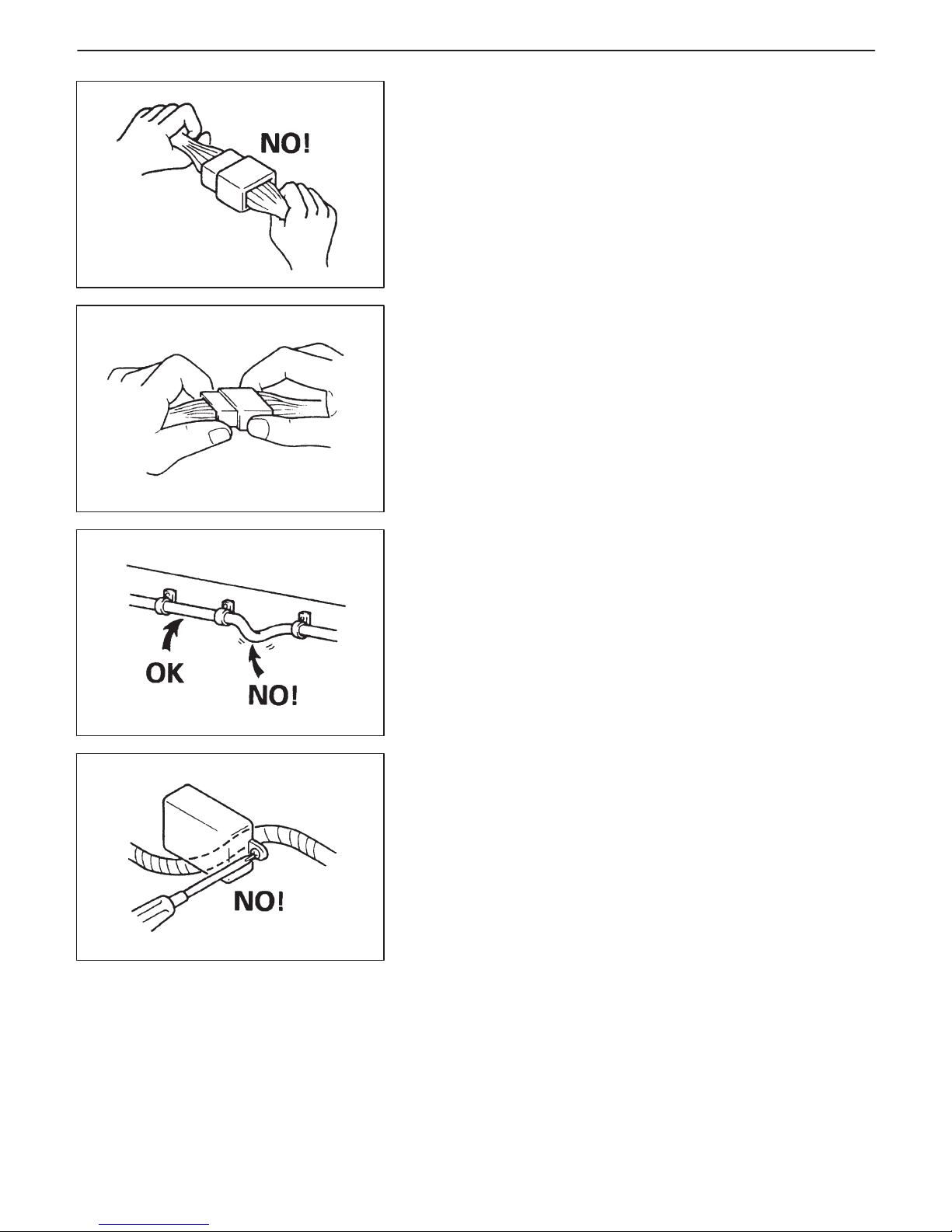
D When disconnecting connectors, never pull the wiring har-
ness. Unlock the connector lock first and then pull them
apart by holding connectors themselves.
D When connecting connectors, also hold connectors and put
them together until they lock securely (a click is heard).
D When installing the wiring harness, fix it with clamps so that
no slack is left.
D When installing vehicle parts, be careful so that the wiring
harness is not interfered with or caught by any other part.
Page 15
GENERAL INFORMATION 0A-11
D Be careful not to touch the electrical terminals of parts which
use microcomputers (e.g. electronic control unit like as
ECM, PCM, P/S controller, etc.). The static electricity from
your body can damage these parts.
D Never connect any tester (voltmeter, ohmmeter, or whatever)
to electronic control unit when its coupler is disconnected.
Attempt to do it may cause damage to it.
D Never connect an ohmmeter to electronic control unit with
its coupler connected to it. Attempt to do it may cause damage to electronic control unit and sensors.
D Be sure to use a specified voltmeter / ohmmeter. Otherwise,
accurate measurements may not be obtained or personal injury may result. If not specified, use a voltmeter with high-impedance (MΩ /V minimum) or a digital type voltmeter.
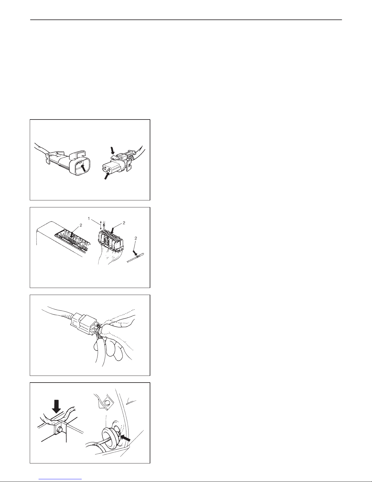
D When taking measurements at electrical connectors using a
tester probe (2), be sure to insert the probe from the wire harness side (backside) of the connector (1).
D When connecting meter probe (2) from terminal side of cou-
pler (1) because it can’t be connected from harness side, use
extra care not to bend male terminal of coupler of force its female terminal open for connection.
In case of such coupler as shown connect probe as shown
to avoid opening female terminal.
Never connect probe where (3) male terminal is supposed to
fit.
D To avoid damage to the harness, protect its part which may
contact against a part forming a sharp angle by winding tape
or the like around it.
Page 16
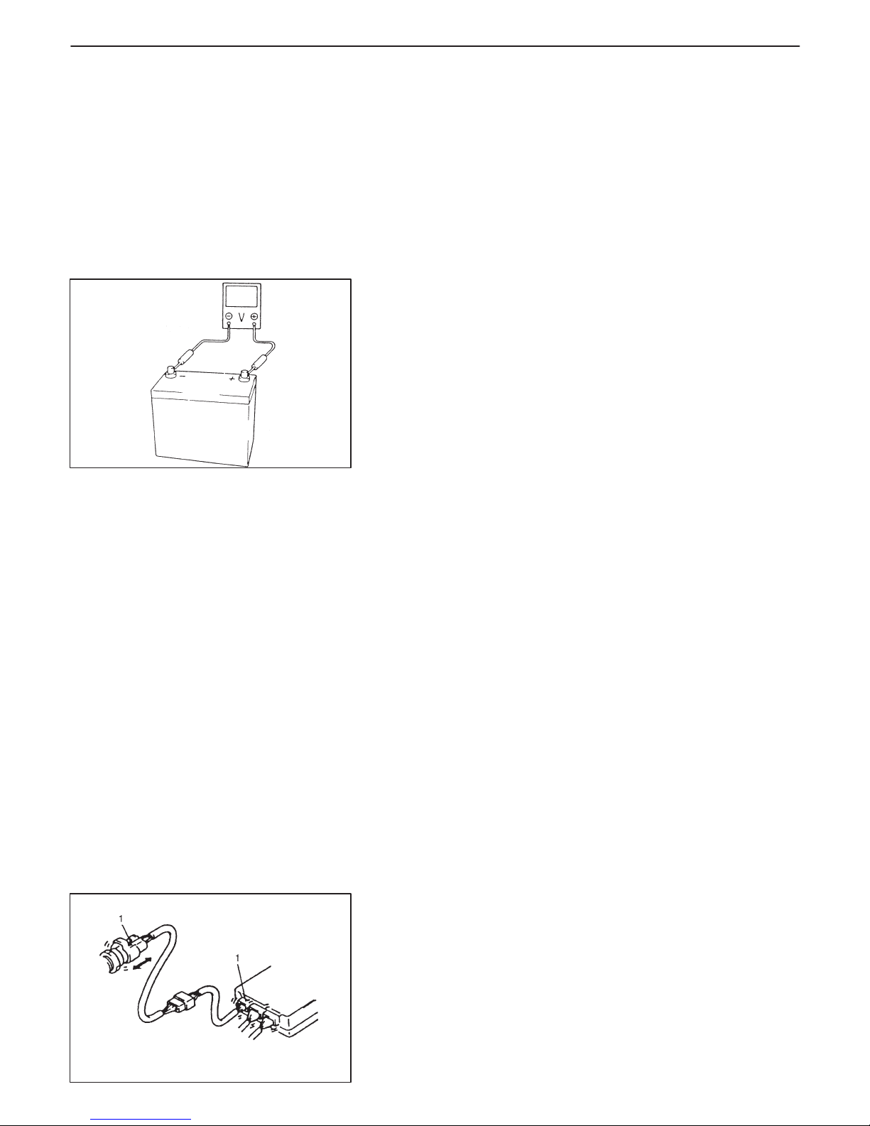
1. Check for loose connection
Sensor
ECM
0A-12 GENERAL INFORMATION
D When checking connection of terminals, check its male half
for bend and female half for excessive opening and both for
locking (looseness), corrosion, dust, etc.
D Before measuring voltage to check for electrical system,
check to make sure that battery voltage is 11 V or higher.
Such terminal voltage check at low battery voltage will lead
to erroneous diagnosis.
ELECTRICAL CIRCUIT INSPECTION
PROCEDURE
While there are various electrical circuit inspection methods, described here is a general method to check its open and short circuit
by using an ohmmeter and a voltmeter.
OPEN CIRCUIT CHECK
Possible causes for the open circuit are as follows. As the cause is
in the connector or terminal in many cases, they need to be checked
particularly carefully.
D Loose connection of connector.
D Poor contact of terminal (due to dirt, corrosion or rust on it, poor
contact tension, entry of foreign object etc.).
D Wire harness being open.
When checking system circuits including an electronic control unit
such as ECM, TCM, ABS control module, etc., it is important to perform careful check, starting with items which are easier to check.
1) Disconnect negative cable from battery.
2) Check each connector at both ends of the circuit being checked
for loose connection. Also check lock condition of connector if
equipped with connector lock.
Page 17
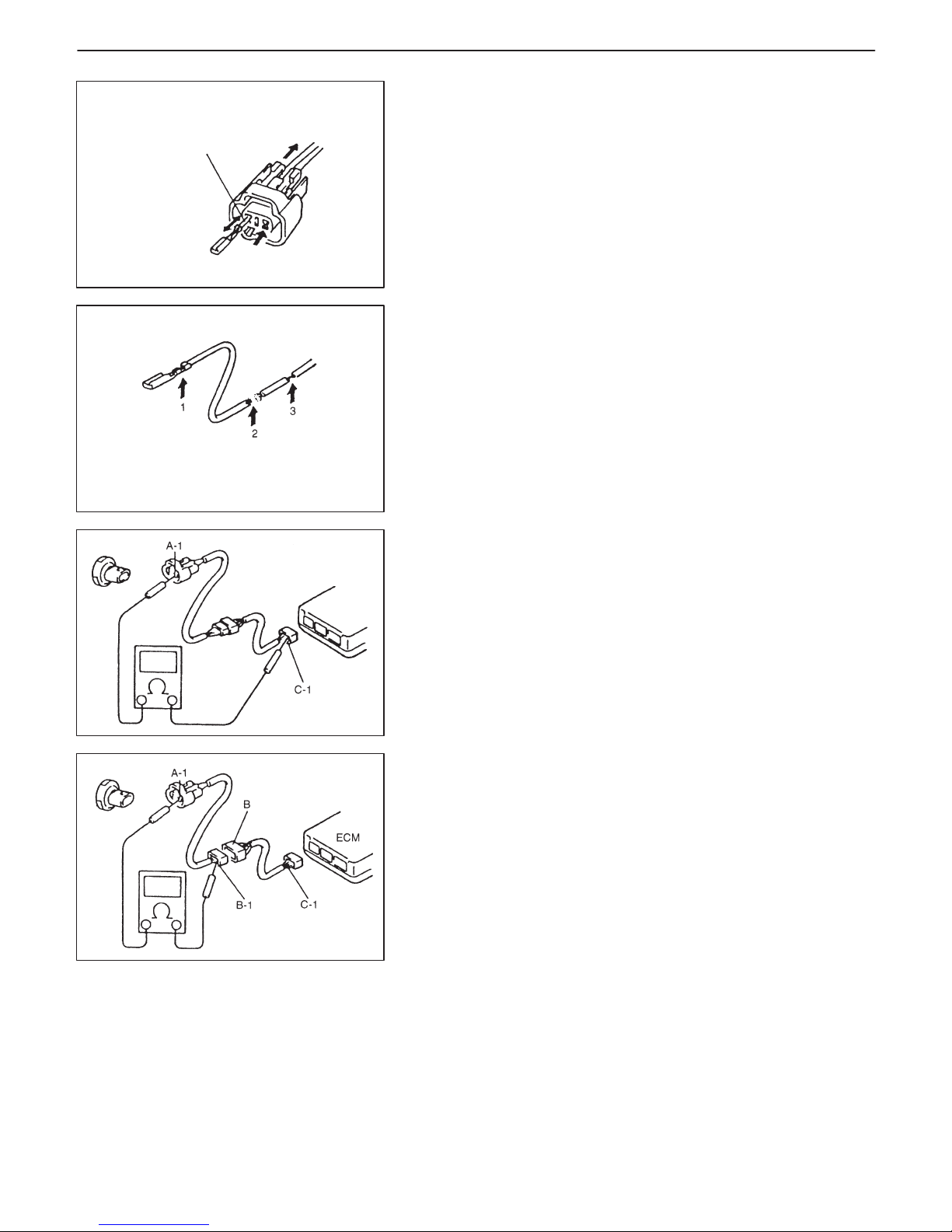
1. Looseness of crimping
2. Open
3. Thin wire (single strand of wire)
Check contact tension by
inserting and removing just
for once
GENERAL INFORMATION 0A-13
3) Using a test male terminal, check both terminals of the circuit being checked for contact tension of its female terminal.
Check each terminal visually for poor contact (possibly caused
by dirt, corrosion, rust, entry of foreign object, etc.).
At the same time, check to make sure that each terminal is
locked in the connector fully.
4) Using continuity check or voltage check procedure described in
the following page, check the wire harness for open circuit and
poor connection with its terminals. Locate abnormality, if any.
Continuity Check
1) Measure resistance between connector terminals at both ends
of the circuit being checked (between A-1 and C-1 in the figure).
If no continuity is indicated (infinity or over limit), that means that
the circuit is open between terminals A-1 and C-1.
2) Disconnect the connector included in the circuit (connector-B in
the figure) and measure resistance between terminals A-1 and
B-1.
If no continuity is indicated, that means that the circuit is open
between terminals A-1 and B-1. If continuity is indicated, there
is an open circuit between terminals B-1 and C-1 or an abnormality in connector-B.
Voltage Check
If voltage is supplied to the circuit being checked, voltage check can
be used as circuit check.
1) With all connectors connected and voltage applied to the circuit
being checked, measure voltage between each terminal and
body ground.
Page 18
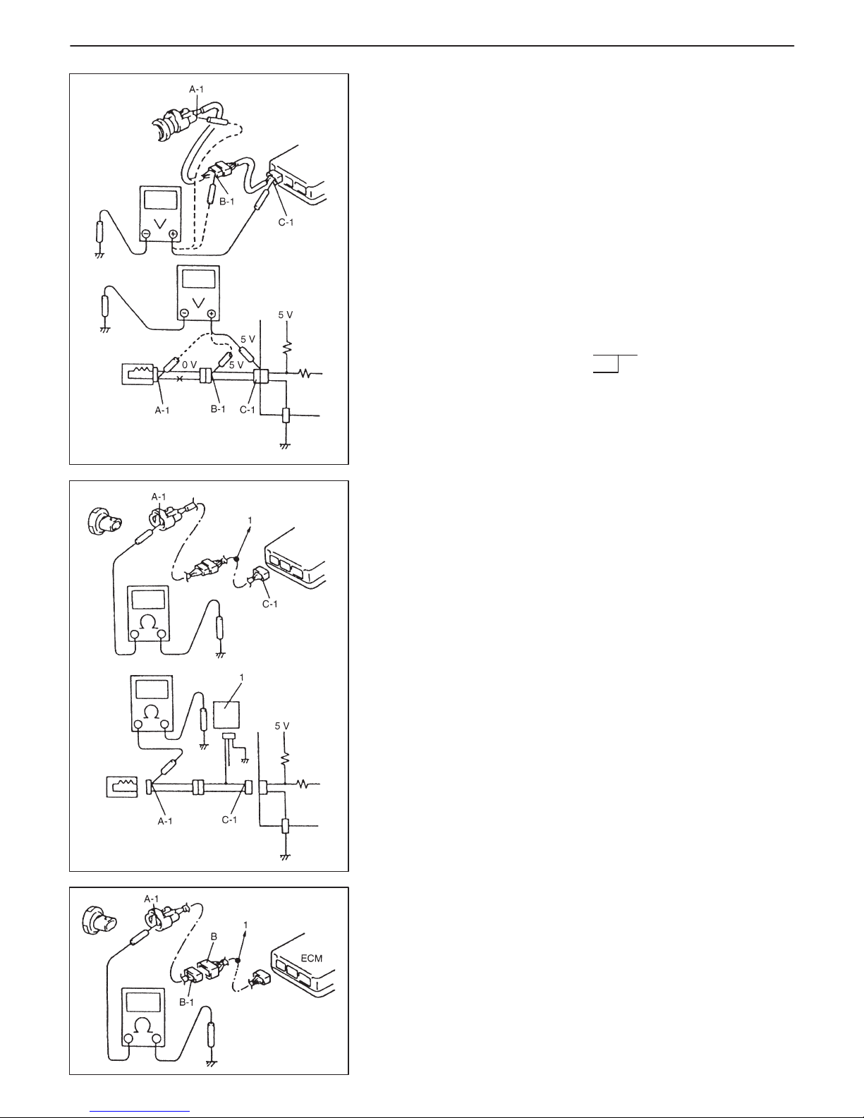
1. Other parts
1. To other parts
2 V voltage drop
0A-14 GENERAL INFORMATION
If measurements were taken as shown in the figure at the left and
results were as listed below, it means that the circuit is open between terminals B-1 and A-1.
Voltage Between:
C-1 and body ground: Approx. 5 V
B-1 and body ground: Approx. 5 V
A-1 and body ground: 0 V
Also, if measured values were as listed below, it means that there
is a resistance (abnormality) of such level that corresponds to the
voltage drop in the circuit between terminals A-1 and B-1.
Voltage Between:
C-1 and body ground: Approx. 5 V
B-1 and body ground: Approx. 5 V
A-1 and body ground: Approx. 3 V
SHORT CIRCUIT CHECK (wire harness to ground)
1) Disconnect negative cable from battery.
2) Disconnect connectors at both ends of the circuit to be checked.
NOTE:
If the circuit to be checked is connected to other parts, disconnect all connectors of those parts.
Otherwise, diagnosis will be misled.
3) Measure resistance between terminal at one end of circuit (A-1
terminal in figure) and body ground. If continuity is indicated, it
means that there is a short to ground between terminals A-1 and
C-1 of the circuit.
4) Disconnect the connector included in circuit (connector B) and
measure resistance between A-1 and body ground.
If continuity is indicated, it means that the circuit is shorted to the
ground between terminals A-1 and B-1.
Page 19
1. Check contact tension by inserting and removing just once
2. Check each terminal for bend and proper alignment
GENERAL INFORMATION 0A-15
INTERMITTENT AND POOR CONNECTION
Most intermittent are caused by faulty electrical connections or wiring, although a sticking relay or solenoid can occasionally be at
fault. When checking it for proper connection, perform careful
check of suspect circuits for:
D Poor mating of connector halves, or terminals not fully seated in
the connector body (backed out).
D Dirt or corrosion on the terminals. The terminals must be clean
and free of any foreign material which could impede proper terminal contact. However, cleaning the terminal with a sand paper or
the like is prohibited.
D Damaged connector body, exposing the terminals to moisture
and dirt, as well as not maintaining proper terminal orientation
with the component or mating connector.
D Improperly formed or damaged terminals.
Check each connector terminal in problem circuits carefully to ensure good contact tension by using the corresponding mating terminal.
If contact tension is not enough, reform it to increase contact tension or replace.
D Poor terminal-to-wire connection.
Check each wire harness in problem circuits for poor connection
by shaking it by hand lightly. If any abnormal condition is found,
repair or replace.
D Wire insulation which is rubbed through, causing an intermittent
short as the bare area touches other wiring or parts of the vehicle.
D Wiring broken inside the insulation. This condition could cause
continuity check to show a good circuit, but if only 1 or 2 strands
of a multi-strand-type wire are intact, resistance could be far too
high.
If any abnormality is found, repair or replace.
Page 20

0A-16 GENERAL INFORMATION
PRECAUTION FOR INSTALLING MOBILE
COMMUNICATION EQUIPMENT
When installing mobile communication equipment such as CB (Citizens-Band)-radio or cellular-telephone, be sure to observe the following precautions.
Failure to follow cautions may adversely affect electronic control
system.
D Keep the antenna as far away as possible from the vehicle’s elec-
tronic control unit.
D Keep the antenna feeder more than 20 cm (7.9 in.) away from
electronic control unit and its wire harnesses.
D Do not run the antenna feeder parallel with other wire harnesses.
D Confirm that the antenna and feeder are correctly adjusted.
Page 21
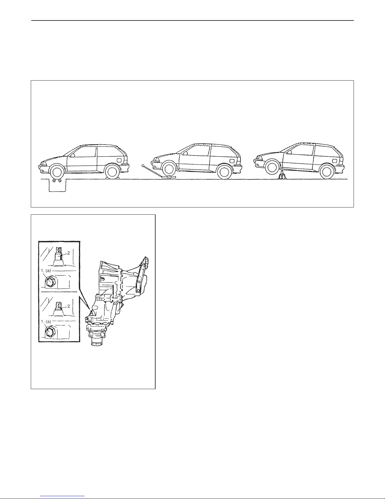
1. Transfer lock bolt
2. Shift fork shaft
Testing following items
D Speedometer
D Chassis dynamo
D Brake
D Wheel balance (on car type)
Towing vehicle with
front or rear
wheels lifted up
Driving front
wheels which are
jacked up
4WD
2WD
GENERAL INFORMATION 0A-17
PRECAUTION IN SERVICING FULL-TIME 4WD VEHICLE
When performing any of the following types of work, be sure to make the vehicle as front wheel drive by cutting
transmission of driving force to the rear wheels. Otherwise, rear wheels are driven and vehicle accidents, damage
and personal injury may result.
SWITCHING FROM 4WD TO 2WD
Set 4WD/2WD select lever located at lower side of transfer driven
case to 2WD as follows.
1) Loosen transfer lock bolt.
2) Push in shift fork shaft fully.
3) With shift fork shaft pushed in, tighten transfer lock bolt.
Tightening Torque
(a): 19 N
.
m (1.9 kg-m, 14.0 lb-ft)
NOTE:
D If shift fork shaft is hard to move, try to move it while turning
it to the right and left little by little. Do the same when setting
back to 4WD after servicing vehicle.
D Upon completion of servicing, always set shift fork shaft
back to 4WD.
Page 22
M/T A/T
G10 G13
[A] [A]
[B] [B]
0A-18 GENERAL INFORMATION
IDENTIFICATION INFORMATION
VEHICLE IDENTIFICATION NUMBER
The number is punched on the front dash panel in the engine room.
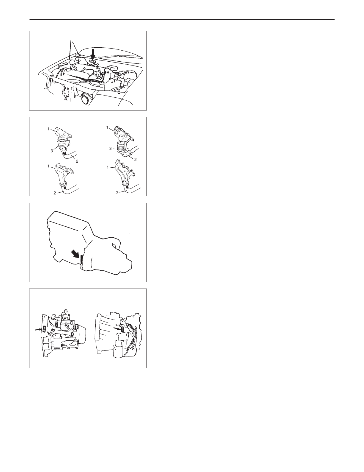
IDENTIFICATION WHETHER VEHICLE
EQUIPPED WITH WU-TWC OR NOT
It can be identified by the shape of exhaust manifold (1) and exhaust pipe (2).
[A]: Vehicle equipped with WU-TWC (3)
[B]: Vehicle not equipped with WU-TWC
ENGINE IDENTIFICATION NUMBER
The number is punched on the cylinder block.
TRANSMISSION IDENTIFICATION NUMBER
The number is punched on the transmission case.
Page 23
NOTE:
Air bag CAUTION / WARNING labels are attached on the vehicle equipped with air bag system only.
Air bag
caution
label
Tire information
placard
Child lock caution label
Fuel limitation
Emission control
information label
(if equipped)
A / C warning label
(if equipped with A / C)
Engine cooling fan
warning label
Air bag warning label on driver air bag
(inflator) module
Air bag warning label on combination
switch / contact coil assembly
Air bag caution label
on steering column
Air bag warning
label on passenger
air bag (inflator)
module
Air bag warning
label on SDM
Radiator cap
warning label
GENERAL INFORMATION 0A-19
WARNING, CAUTION AND INFORMATION LABELS
The figure below shows main labels among others that are attached to vehicle component parts.
When servicing and handling parts, refer to WARNING/ CAUTION instructions printed on labels.
If any WARNING/ CAUTION label is found stained or damaged, clean or replace it as necessary.
Page 24
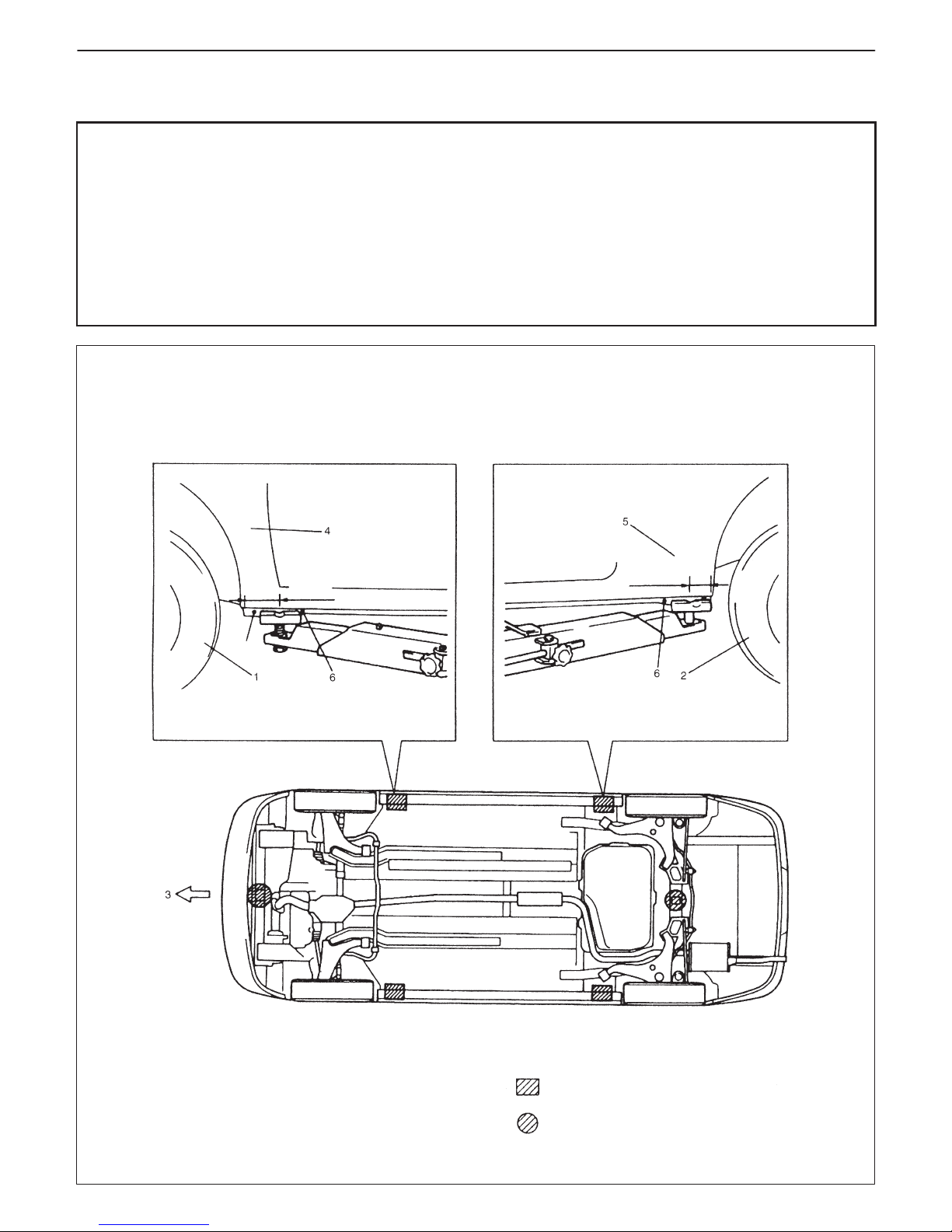
1. Front left tire
2. Rear left tire
3. Front
4. Front fender left panel
5. Rear left panel
6. Embossed-mark
When using frame contact hoist:
Front Support Location Rear Support Location
110 mm
(4.3 in.)
SUPPORT LOCATION
Forward of embossed-mark
120 mm
(4.7 in.)
SUPPORT LOCATION
Rearward of embossed-mark
: Support position for frame contact hoist and safety stand
: Floor jack position
Bolt
0A-20 GENERAL INFORMATION
VEHICLE LIFTING POINTS
WARNING:
D Before applying hoist to underbody, always take vehicle balance throughout service into consider-
ation. Vehicle balance on hoist may change depending of what part to be removed.
D Before lifting up the vehicle, check to be sure that end of hoist arm is not in contact with brake pipe,
fuel pipe, bracket or any other part.
D When using frame contact hoist, apply hoist as shown (right and left at the same position). Lift up the
vehicle till 4 tires are a little off the ground and make sure that the vehicle will not fall off by trying to
move vehicle body in both ways. Work can be started only after this confirmation.
D Make absolutely sure to lock hoist after vehicle is hoisted up.
Page 25
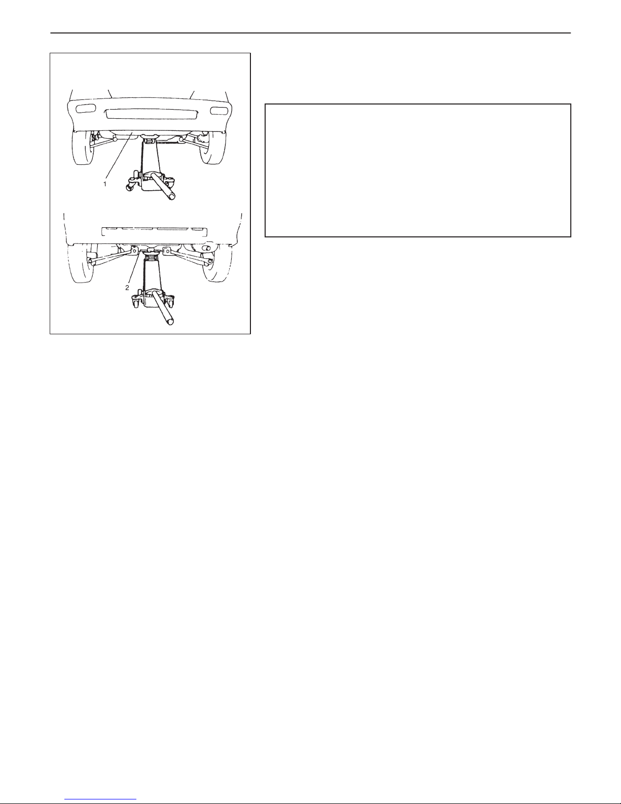
When using floor jack:
GENERAL INFORMATION 0A-21
In raising front or rear vehicle end off the floor by jacking, be sure
to put the jack against the center portion of front cross member (1)
or rear cross member (2).
WARNING:
D Never apply jack against suspension parts (i.e., stabilizer,
etc.) or vehicle floor, or it may get deformed.
D If the vehicle to be jacked up only at the front or rear end,
be sure to block the wheels on ground in order to ensure
safety.
After the vehicle is jacked up, be sure to support it on
stands. It is extremely dangerous to do any work on the
vehicle raised on jack alone.
To perform service with either front or rear vehicle end jacked up,
be sure to place safety stands under body so that body is securely
supported. And then check to ensure that body does not slide on
safety stands and the vehicle is held stable for safety’s sake.
Page 26

0A-22 GENERAL INFORMATION
A
ABS : Anti-Lock Brake System
ATDC : After Top Dead Center
API : American Petroleum Institute
ATF : Automatic Transmission Fluid
ALR : Automatic Locking Retractor
AC : Alternating Current
A/T : Automatic Transmission
A/C : Air Conditioning
ABDC : After Bottom Dead Center
A/F : Air Fuel Mixture Ratio
A-ELR : Automatic-Emergency Locking
Retractor
B
B+ : Battery Positive Voltage
BTDC : Before Top Dead Center
BBDC : Before Bottom Dead Center
C
CKT : Circuit
CMP Sensor : Camshaft Position Sensor
(Crank Angle Sensor, CAS)
CO : Carbon Monoxide
CPP Switch : Clutch Pedal Position Switch
(Clutch Switch, Clutch Start
Switch)
CPU : Central Processing Unit
CRS : Child Restraint System
D
DC : Direct Current
DLC : Data Link Connector (Assembly
Line Diag. Link, ALDL, Serial
Data Link, SDL)
DOHC : Double Over Head Camshaft
DOJ : Double Offset Joint
DRL : Daytime Running Light
DTC : Diagnostic Trouble Code
(Diagnostic Code)
E
EBCM : Electronic Brake Control
Module, ABS Control Module
ECM : Engine Control Module
ECT Sensor : Engine Coolant Temperature
Sensor (Water Temp. Sensor,
WTS)
EGR : Exhaust Gas Recirculation
EGRT Sensor : EGR Temperature Sensor
(Recirculated Exhaust
Gas Temp. Sensor, REGTS)
EFE Heater : Early Fuel Evaporation Heater
(Positive Temperature
Coefficient, PTC Heater)
ELR : Emergency Locking Retractor
EPS : Electronic Power Steering
EVAP : Evaporative Emission
EVAP Canister : Evaporative Emission Canister
(Charcoal Canister)
F
4WD : 4 Wheel Drive
G
GEN : Generator
GND : Ground
H
HC : Hydrocarbons
HO2S : Heated Oxygen Sensor
I
IAC Valve : Idle Air Control Valve (Idle
Speed Control Solenoid Valve,
ISC Solenoid Valve)
IAT Sensor : Intake Air Temperature Sensor
(Air temperature Sensor, ATS)
ICM : Immobilizer Control Module
IG : Ignition
ISC Actuator : Idle Speed Control Actuator
(Motor)
ABBREVIATIONS AND SYMBOLS MAY BE USED IN THIS MANUAL
ABBREVIATIONS
Page 27

GENERAL INFORMATION 0A-23
L
LH : Left Hand
LSPV : Load Sensing Proportioning
Valve
M
MAF Sensor : Mass Air Flow Sensor (Air Flow
Sensor, AFS, Air Flow Meter,
AFM)
MAP Sensor : Manifold Absolute Pressure
Sensor (Pressure Sensor, PS)
Max : Maximum
MFI : Multiport Fuel Injection
(Multipoint Fuel Injection)
Min : Minimum
MIL : Malfunction Indicator Lamp
M/T : Manual Transmission
N
NOx : Nitrogen Oxides
O
OBD : On-Board Diagnostic System
(Self-Diagnosis Function)
O/D : Overdrive
OHC : Over Head Camshaft
P
PNP : Park /Neutral Position
P/S : Power Steering
PSP Switch : Power Steering Pressure Switch
(P/S Pressure Switch)
PCM : Powertrain Control Module
PCV : Positive Crankcase Ventilation
R
RH : Right Hand
S
SAE : Society of Automotive
Engineers
SDM : Sensing and Diagnostic Module
(Air Bag Controller, Air Bag
Control Module)
SFI : Sequential Multiport Fuel
Injection
SOHC : Single Over Head Camshaft
T
TBI : Throttle Body Fuel Injection
(Single-Point Fuel Injection,
SPI)
TCC : Torque Converter Clutch
TCM : Transmission Control Module
(A/T Controller, A/ T Control
Module)
TP Sensor : Throttle Position Sensor
TVV : Thermal Vacuum Valve
(Thermal Vacuum Switching
Valve, TVSV, Bimetal Vacuum
Switching Valve, BVSV)
TWC : Three-Way Catalytic Converter
(Three-Way Catalyst)
2WD : 2 Wheel Drive
V
VIN : Vehicle Identification Number
VSS : Vehicle Speed Sensor
W
WU-OC : Warm Up Oxidation Catalytic
Converter
WU-TWC : Warm Up Three-Way Catalytic
Converter
Page 28
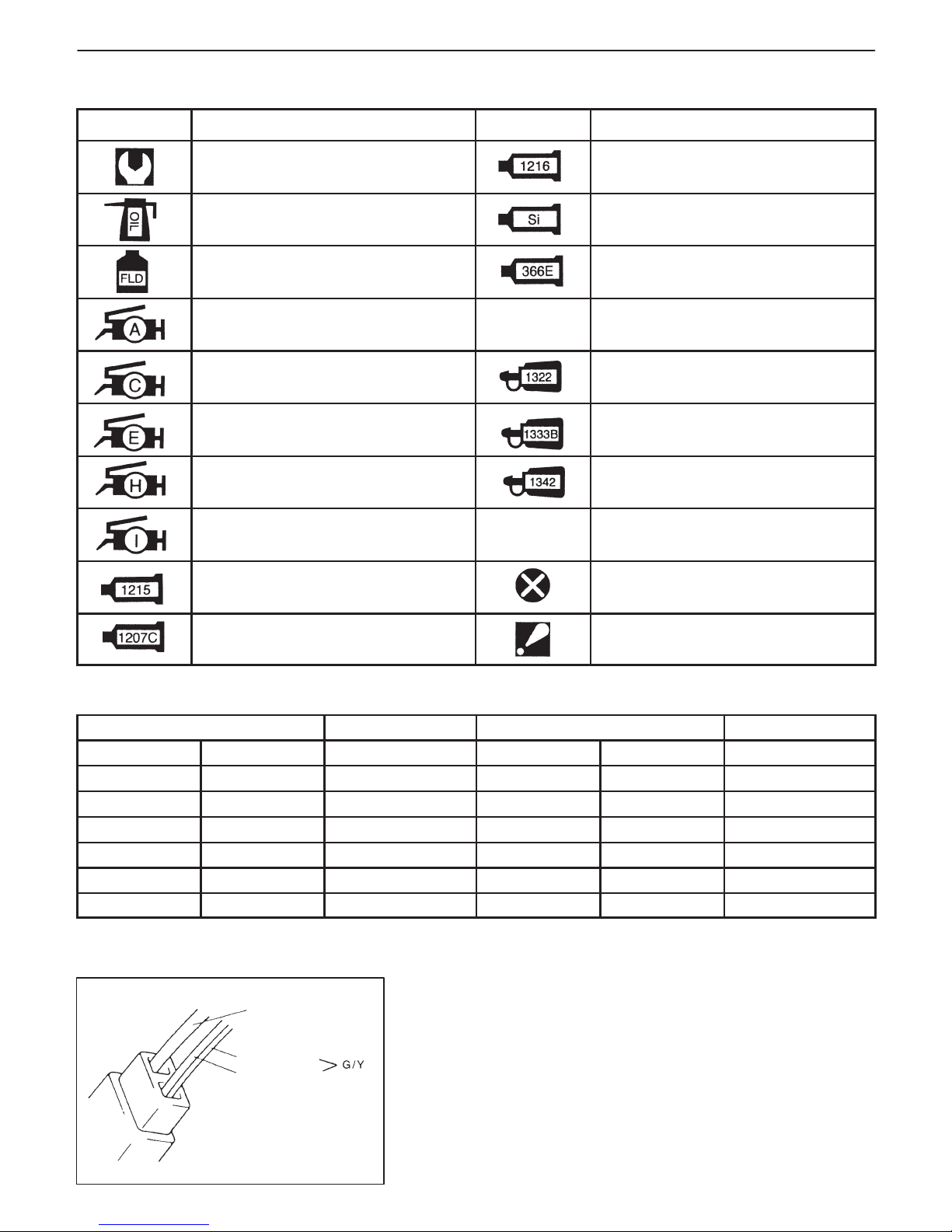
G (Base Color)
G (Base Color)
Y (Stripe Color)
0A-24 GENERAL INFORMATION
SYMBOLS
SYMBOL DEFINITION SYMBOL DEFINITION
Tightening torque Apply SUZUKI BOND NO. 1216
99000-31160
Apply oil (Engine, transmission,
transfer, differential)
Apply SILICONE SEALANT
99000-31120
Apply fluid (Brake, power steering or
automatic transmission fluid)
Apply SEALING COMPOUND 366E
99000-31090
Apply SUZUKI SUPER GREASE A
99000-25010
Apply SUZUKI SUPER GREASE C
99000-25030
Apply THREAD LOCK 1322
99000-32110
Apply SUZUKI SUPER GREASE E
99000-25050
Apply THREAD LOCK 1333B
99000-32020
Apply SUZUKI SUPER GREASE H
99000-25120
Apply THREAD LOCK 1342
99000-32050
Apply SUZUKI SUPER GREASE I
99000-25210
Apply SUZUKI BOND NO. 1215
99000-31110
Do not reuse
Apply SUZUKI BOND NO. 1207C
99000-31150
Note on reassembly
WIRE COLOR SYMBOLS
Symbol Wire Color Symbol Wire Color
B BLK Black O, Or ORN Orange
Bl BLU Blue R RED Red
Br BRN Brown W WHT White
G GRN Green Y YEL Yellow
Gr GRY Gray P PNK Pink
Lbl LT BLU Light blue V PPL Violet
Lg LT GRN Light green
There are two kinds of colored wire used in this vehicle. One is
single-colored wire and the other is dual-colored (striped) wire.
The single-colored wire uses only one color symbol (i.e. “G”).
The dual-colored wire uses two color symbols (i.e. “G/Y”). The first
symbol represents the base color of the wire (“G” in the figure) and
the second symbol represents the color of the stripe (“Y” in the figure).
Page 29
GENERAL INFORMATION 0A-25
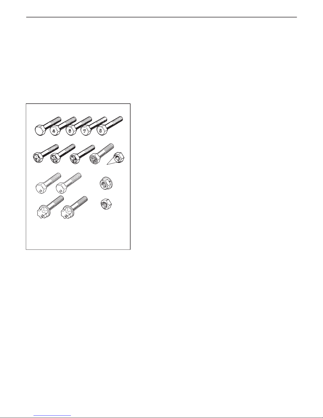
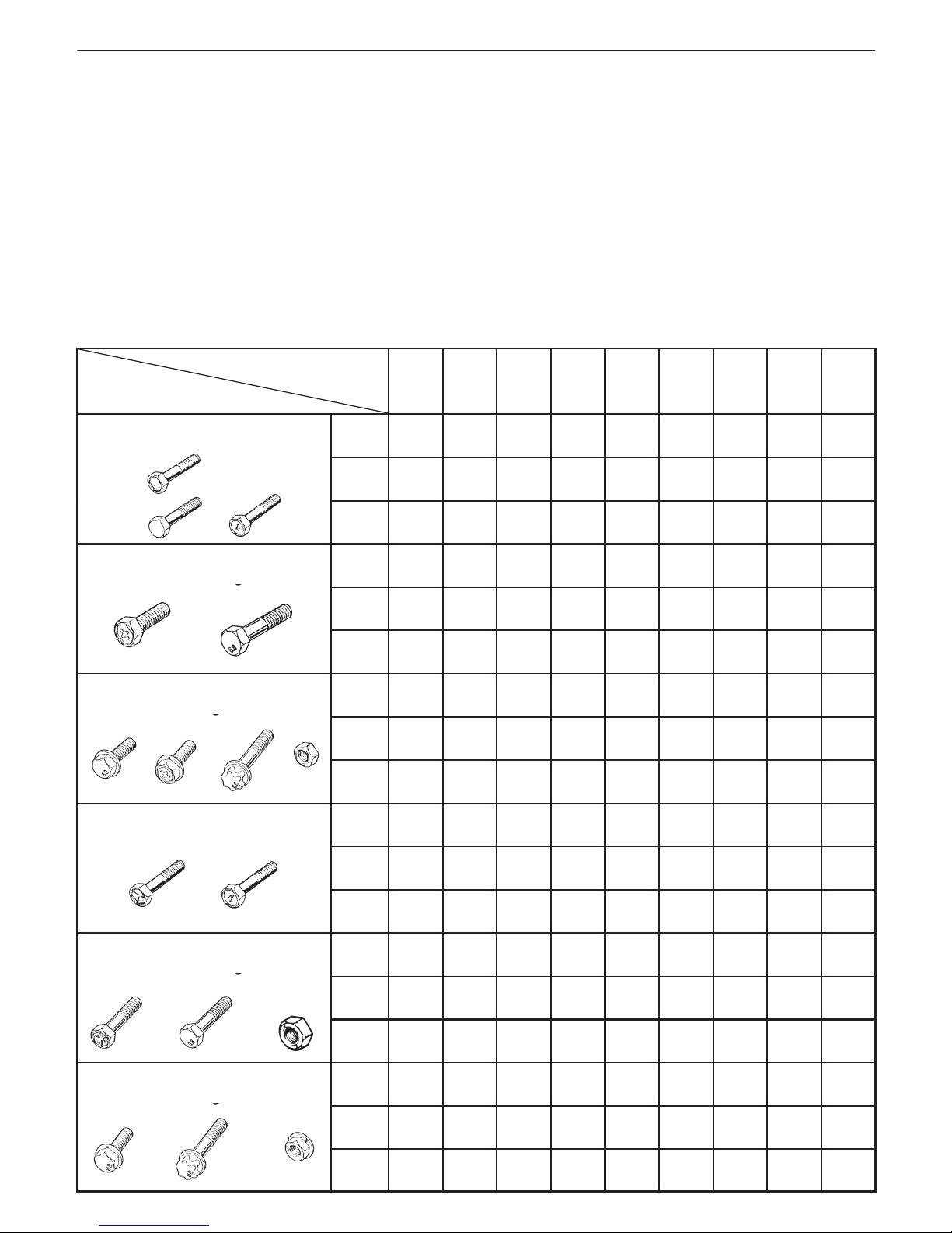
METRIC BOLTS-IDENTIFICATION CLASS NUMBERS
OR MARKS CORRESPOND TO BOLT
STRENGTH-INCREASING NUMBERS REPRESENT
INCREASING STRENGTH.
NUT STRENGTH
IDENTIFICATION
FASTENERS INFORMATION
METRIC FASTENERS
Most of the fasteners used for this vehicle are metric fasteners.
When replacing any fasteners, it is most important that replacement
fasteners be the correct diameter, thread pitch and strength.
FASTENER STRENGTH IDENTIFICATION
Most commonly used metric fastener strength property classes are
4T, 6.8, 7T, 8.8 and radial line with the class identification embossed
on the head of each bolt. Some metric nuts will be marked with
punch, 6 or 8 mark strength identification on the nut face. Figure
shows the different strength markings.
When replacing metric fasteners, be careful to use bolts and nuts
of the same strength or greater than the original fasteners (the
same number marking or higher). It is likewise important to select
replacement fasteners of the correct diameter and thread pitch.
Correct replacement bolts and nuts are available through the parts
division.
Page 30
0A-26 GENERAL INFORMATION
Self-lock
nut
STANDARD TIGHTENING TORQUE
Each fastener should be tightened to the torque specified in each section of this manual. If no description or specification is provided, refer to the following tightening torque chart for the applicable torque for each fastener. When
a fastener of greater strength than the original one is used, however, use the torque specified for the original fastener.
NOTE:
D For the flanged bolt, flanged nut and self-lock nut of 4T and 7T strength, add 10% to the tightening torque
given in the chart below.
D The chart below is applicable only where the fastened parts are made of steel or light alloy.
Tightening torque chart
Thread Diameter (Nominal Diameter)
(mm)
4 5 6 8 10 12 14 16 18
Strength
A equivalent of 4T strength
fastener
N.m 1.5 3.0 5.5 13 29 45 65 105 160
kg-m 0.15 0.30 0.55 1.3 2.9 4.5 6.5 10.5 16
lb-ft 1.0 2.5 4.0 9.5 21.0 32.5 47.0 76.0 116.0
A equivalent of 6.8 strength
fastener without flange
N.m 2.4 4.7 8.4 20 42 80 125 193 280
g
kg-m 0.24 0.47 0.84 2.0 4.2 8.0 12.5 19.3 28
lb-ft 2.0 3.5 6.0 14.5 30.5 58.0 90.5 139.5 202.5
A equivalent of 6.8 strength
fastener with flange
N.m 2.4 4.9 8.8 21 44 84 133 203 298
g
kg-m 0.24 0.49 0.88 2.1 4.4 8.4 13.3 20.3 29.8
lb-ft 2.0 3.5 6.5 15.5 32.0 61.0 96.5 147.0 215.5
A equivalent of 7T strength
fastener
N.m 2.3 4.5 10 23 50 85 135 210 240
kg-m 0.23 0.45 1.0 2.3 5.0 8.5 13.5 21 24
lb-ft 2.0 3.5 7.5 17.0 36.5 61.5 98.0 152.0 174.0
A equivalent of 8.8 strength
fastener without flange
N.m 3.1 6.3 11 27 56 105 168 258 373
g
kg-m 0.31 0.63 1.1 2.7 5.6 10.5 16.8 25.8 37.3
lb-ft 2.5 4.5 8.0 19.5 40.5 76.0 121.5 187.0 270.0
A equivalent of 8.8 strength
fastener with flange
N.m 3.2 6.5 12 29 59 113 175 270 395
g
kg-m 0.32 0.65 1.2 2.9 5.9 11.3 17.5 27 39.5
lb-ft 2.5 5.0 9.0 21.0 43.0 82.0 126.5 195.5 286.0
Page 31

0B
MAINTENANCE AND LUBRICATION 0B-1
SECTION 0B
MAINTENANCE AND LUBRICATION
WARNING:
For vehicles equipped with Supplemental Restraint (Air Bag) System:
D Service on and around the air bag system components or wiring must be performed only by an autho-
rized SUZUKI dealer. Refer to “Air Bag System Components and Wiring Location View” under “General Description” in air bag system section in order to confirm whether you are performing service on
or near the air bag system components or wiring. Please observe all WARNINGS and “Service Precautions” under “On-Vehicle Service” in air bag system section before performing service on or around
the air bag system components or wiring. Failure to follow WARNINGS could result in unintentional
activation of the system or could render the system inoperative. Either of these two conditions may
result in severe injury.
D Technical service work must be started at least 90 seconds after the ignition switch is turned to the
“LOCK” position and the negative cable is disconnected from the battery. Otherwise, the system may
be activated by reserve energy in the Sensing and Diagnostic Module (SDM).
CONTENTS
MAINTENANCE SCHEDULE 0B- 2. . . . . . . . . . . . . . . . . . . . . . . . . . . . . . . . . . . . . . . . . . . . . . . . . . . . . . . . . . . . . . . .
Normal Condition Schedule 0B- 2. . . . . . . . . . . . . . . . . . . . . . . . . . . . . . . . . . . . . . . . . . . . . . . . . . . . . . . . . . . . . . . .
Maintenance Recommended Under Severe Driving Conditions 0B- 4. . . . . . . . . . . . . . . . . . . . . . . . . . . . . . . . .
MAINTENANCE SERVICE 0B- 5. . . . . . . . . . . . . . . . . . . . . . . . . . . . . . . . . . . . . . . . . . . . . . . . . . . . . . . . . . . . . . . . . .
Engine 0B- 5. . . . . . . . . . . . . . . . . . . . . . . . . . . . . . . . . . . . . . . . . . . . . . . . . . . . . . . . . . . . . . . . . . . . . . . . . . . . . . . . . .
Ignition System 0B-10. . . . . . . . . . . . . . . . . . . . . . . . . . . . . . . . . . . . . . . . . . . . . . . . . . . . . . . . . . . . . . . . . . . . . . . . . . .
Fuel System 0B-10. . . . . . . . . . . . . . . . . . . . . . . . . . . . . . . . . . . . . . . . . . . . . . . . . . . . . . . . . . . . . . . . . . . . . . . . . . . . .
Emission Control System 0B-12. . . . . . . . . . . . . . . . . . . . . . . . . . . . . . . . . . . . . . . . . . . . . . . . . . . . . . . . . . . . . . . . . .
Brake 0B-12. . . . . . . . . . . . . . . . . . . . . . . . . . . . . . . . . . . . . . . . . . . . . . . . . . . . . . . . . . . . . . . . . . . . . . . . . . . . . . . . . . .
Chassis and Body 0B-14. . . . . . . . . . . . . . . . . . . . . . . . . . . . . . . . . . . . . . . . . . . . . . . . . . . . . . . . . . . . . . . . . . . . . . . .
Final Inspection 0B-20. . . . . . . . . . . . . . . . . . . . . . . . . . . . . . . . . . . . . . . . . . . . . . . . . . . . . . . . . . . . . . . . . . . . . . . . . .
RECOMMENDED FLUIDS AND LUBRICANTS 0B-21. . . . . . . . . . . . . . . . . . . . . . . . . . . . . . . . . . . . . . . . . . . . . . . .
Page 32

0B-2 MAINTENANCE AND LUBRICATION
MAINTENANCE SCHEDULE
NORMAL CONDITION SCHEDULE
Interval:
This interval should be
judg
ed b
y
This table includes services as scheduled up to 90,000 km (54,000 miles)
mileage. Beyond 90,000 km (54,000 miles), carry out the same services at
the same intervals respectively.
jg y
odometer reading or months,
Km ( 1,000) 15
30 45 60 75 90
whichever comes first.
Miles ( 1,000) 9
18 27 36 45 54
Months 12
24 36 48 60 72
1. ENGINE
1-1. Drive belt (tension,
V-belt I
R I R I R
damage)
V-rib belt (Flat type)
–
– I – – R
1-2. Camshaft timing belt Replace every 100,000 km (60,000 miles).
1-3. Valve lash (1.3 liter engine) – I – I – I
1-4. Engine oil
Vehicle with O2S (SG, SH, SJ) R
R R R R R
and oil filter
Vehicle with O2S (SE, SF)
Vehicle without O2S
Replace every 10,000 km (6,000 miles)
or 8 months
1-5. Engine coolant – R – R – R
1-6. Exhaust system (leakage, damage, tightness) – I – I – I
2. IGNITION SYSTEM
2-1. Spark plugs When unleaded
fuel is used
Vehicle
without
O2S
– R – R – R
Vehicle
with O2S
– – R – – R
When leaded fuel is used Refer to “Severe Driving Condition” schedule.
2-2. Distributor cap and rotor (if equipped) – – I – – I
3. FUEL SYSTEM
3-1. Air cleaner filter
Paved-road I
I R I I R
Dusty condition Refer to “Severe Driving Condition” schedule.
3-2. Fuel lines (deterioration, leakage, damage) – I – I – I
3-3. Fuel tank – – I – – I
NOTES:
D For Item 2-1 “spark plugs”, replace every 50,000 km if the local law requires.
D For Sweden, Item 2-1, 4-1 and 4-2 should be performed by odometer reading only.
D For Item 1-2 Camshaft timing belt: This belt may be replaced every 90,000 km (54,000 miles) according
to customer’s maintenance convenience.
Page 33

MAINTENANCE AND LUBRICATION 0B-3
Interval:
This interval should be
judg
ed b
y
This table includes services as scheduled up to 90,000 km (54,000 miles)
mileage. Beyond 90,000 km (54,000 miles), carry out the same services at
the same intervals respectively.
This interval should be judged by
odometer reading or months,
Km ( 1,000)
15 30 45 60 75 90
g
whichever comes first.
Miles ( 1,000)
9 18 27 36 45 54
Months
12 24 36 48 60 72
4. EMISSION CONTROL SYSTEM
4-1. PCV (Positive Crankcase Ventilation)
Valve
Vehicle
without
O2S
– – I – – I
Vehicle
with O2S
– – – – – I
4-2. Fuel evaporative emission control system – – – – – I
5. BRAKE
5-1.
Brake discs and pads
I I I I I I
Brake drums and shoes
– I – I – I
5-2. Brake hoses and pipes – I – I – I
5-3. Brake fluid – R – R – R
5-4. Brake lever and cable Inspect at first 15,000 km (9,000 miles) only.
6. CHASSIS AND BODY
6-1. Clutch pedal (for manual transmission) – I – I – I
6-2. Tires/wheel discs I I I I I I
6-3. Propeller shaft (4WD) and drive shafts – – I – – I
6-4. Suspension system – I – I – I
6-5. Steering system – I – I – I
6-6. Power steering (if equipped) I I I I I I
6-7. Manual transmission oil I – R – – R
6-8. Automatic transmission
Fluid level
– I – I – I
Fluid change Replace every 165,000 km (99,000 miles).
Fluid hose
– – – R – –
6-9. Rear differential oil (4WD) (R: 1st 15,000 km only) R or I – I – I –
6-10. All latches, hinges and locks – I – I – I
NOTES:
D “R”: Replace or change
D “I”: Inspect and correct or replace if necessary
Page 34

0B-4 MAINTENANCE AND LUBRICATION
MAINTENANCE RECOMMENDED UNDER SEVERE DRIVING CONDITIONS
If the vehicle is usually used under the conditions corresponding to any severe condition code given below, it is
recommended that applicable maintenance operation be performed at the particular interval as given in the chart
below.
Severe condition code
A – Repeated short trips F – Leaded fuel use
B – Driving on rough and/or muddy roads G – (For Diesel engine) Town use/ Towing a trailer/
C – Driving on dusty roads Sustained high speed driving/
D – Driving in extremely cold weather and/or Hot climates above 30_C (86_F)/
salted roads Low quality lubricants or fuel
E – Repeated short trips in extremely cold weather H – Trailer towing (if admitted)
Severe
Condition Code
Maintenance
Maintenance
Operation
Maintenance Interval
ITEM 1-1
I
Every 15,000 km (9,000 miles)
or 12 months
– B C D – – – –
Drive belt (V-rib belt)
R
Every 45,000 km (27,000 miles)
or 36 months
A – C D E F – H
ITEM 1-4
Engine oil and filter
R
Every 5,000 km (3,000 miles)
or 4 months
A B C – E F – H
ITEM 2-1
Spark plugs
R
Every 10,000 km (6,000 miles)
or 8 months
I
Every 2,500 km (1,500 miles)
– – C – – – – –
ITEM 3-1
Air cleaner filter *1
R
Every 30,000 km (18,000 miles)
or 24 months
– B C D – – – H
ITEM 6-2
Wheel bearings
I
Every 15,000 km (9,000 miles)
or 12 months
– B – D E – – H
ITEM 6-3
Propeller shaft (4WD) and drive
shafts
I
Every 15,000 km (9,000 miles)
or 12 months
– B – – E – – H
ITEM 6-7/6-8
Manual transmission oil and
differential oil (4WD)
R
Every 30,000 km (18,000 miles)
or 24 months
– B – – E – – H
ITEM 6-9
Automatic transmission fluid
R
Every 30,000 km (18,000 miles)
or 24 months
NOTES:
D “R”: Replace or change
D “I”: Inspect and correct or replace if necessary
D *1: Inspect or replace more frequently if necessary
Page 35

Vehicle with A/C
Vehicle with A/C and power steering
Vehicle with power steering
1. A/C compressor pulley
2. Power steering pump pulley
3. Tension pulley
4. Crankshaft pulley
MAINTENANCE AND LUBRICATION 0B-5
MAINTENANCE SERVICE
ENGINE
ITEM 1-1
Drive Belt Inspection and Replacement
WARNING:
Disconnect negative cable at battery before checking and
replacing belt.
A/C Compressor and/or Power Steering Pump Drive Belt
Inspection (If equipped)
1) Detach air cleaner assembly from vehicle body and shift its position.
2) Inspect belt for wear, deterioration and tension.
Replace or adjust, if necessary.
A/C compressor and / or power steering pump drive belt
tension “a”:
7 – 9 mm (0.28 – 0.35 in.) deflection under 10 kg or 22 lb
pressure
A/C Compressor and/ or Power Steering Pump Drive Belt
Replacement
1) Disconnect negative cable from battery.
2) Remove engine under cover of right side.
3) Loosen belt tension and replace belt with new one.
4) Adjust belt tension to specification referring to SECTION 1B or
SECTION 3B1.
5) Install engine under cover and connect negative cable to battery.
Water Pump Belt Inspection
1) Inspect belt for cracks, cuts, deformation, wear and cleanliness.
Replace, if necessary.
2) Check pump belt for tension and adjust it as necessary.
Water pump belt tension “a”:
6 – 8 mm (0.24 – 0.32 in.) deflection under 10 kg or 22 lb
pressure
Page 36

1. Thickness gauge
IN
EX
0B-6 MAINTENANCE AND LUBRICATION
Water Pump Belt Replacement
Replace belt with a new one. Refer to SECTION 6B for replacement
procedure of pump belt.
NOTE:
When replacing belt with a new one, adjust belt tension to
5 – 7 mm (0.20 – 0.27 in.).
ITEM 1-2
Camshaft Timing Belt Replacement
Replace belt with new one. Refer to SECTION 6A or 6A1 for replacement procedure.
CAUTION:
D Do not bend or twist timing belt.
D Do not allow timing belt to come into contact with oil, wa-
ter, etc.
ITEM 1-3
Valve Lash Inspection (1.3 liter engine only)
1) Remove cylinder head cover.
2) Inspect intake and exhaust valve lash and adjust as necessary.
Refer to SECTION 6A1 for valve lash inspection and adjustment
procedure.
Valve
lash
When cold
(Coolant temperature is
15 – 25_C or 59 – 77_F)
When hot
(Coolant temperature is
60 – 68_C or
140 – 154_F)
(
gap
)
specifi-
Intake
0.13 – 0.17 mm
(0.005 – 0.007 in.)
0.17 – 0.21 mm
(0.007 – 0.008 in.)
cation
Exhaust
0.23 – 0.27 mm
(0.009 – 0.011 in.)
0.28 – 0.32 mm
(0.011 – 0.013 in.)
Special Tool
(A): 09917-18211
Tightening Torque
(a): 12 N
.
m (1.2 kg-m, 8.5 lb-ft)
3) Install cylinder head cover and tighten bolts to specification.
Page 37
MAINTENANCE AND LUBRICATION 0B-7
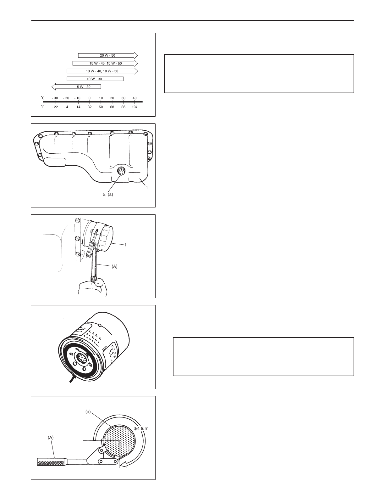
Proper Engine Oil Viscosity Chart
1. Oil pan
2. Oil drain plug
1. Oil filter
ITEM 1-4
Engine Oil and Filter Change
WARNING:
New and used engine oil can be hazardous.
Be sure to read “WARNING” in General Precaution in SEC-
TION 0A and observe what in written there.
Use engine oil of SE, SF, SG, SH or SJ grade.
Select the appropriate oil viscosity according to the left chart.
Before draining engine oil, check engine for oil leakage. If any evidence of leakage is found, make sure to correct defective part before proceeding to following work.
1) Drain engine oil by removing drain plug.
2) After draining oil, wipe drain plug clean. Reinstall drain plug, and
tighten it securely as specified below.
Tightening Torque
(a): 35 N
.
m (3.5 kg-m, 25.5 lb-ft)
3) Loosen oil filter by using oil filter wrench (Special tool).
Special Tool
(A): 09915-47330
4) Apply engine oil to new oil filter O-ring.
5) Screw new filter on oil filter stand by hand until filter O-ring contacts mounting surface.
CAUTION:
To tighten oil filter properly, it is important to accurately
identify the position at which filter O-ring first contacts
mounting surface.
6) Tighten filter 3/ 4 turn from the point of contact with mounting surface using an oil filter wrench.
Special Tool
(A): 09915-47330
Tightening Torque (Reference)
(a): 14 N
.
m (1.4 kg-m, 10.5 lb-ft)
Page 38

1. Full level mark (hole)
2. Low level mark (hole)
Oil pan capacity
Oil filter capacity
Others
Total
1.0 L and 1.3 L Engine
About 3.1 liters
(6.5/5.5 US/ lmp pt.)
About 0.2 liter
(0.4/0.3 US/ lmp pt.)
About 0.3 liter
(0.6/0.5 US/ lmp pt.)
About 3.6 liters
(7.5/6.3 US/ lmp pt.)
0B-8 MAINTENANCE AND LUBRICATION
7) Replenish oil until oil level is brought to FULL level mark on dipstick (oil pan and oil filter capacity). Filler inlet is at the top of cylinder head cover.
8) Start engine and run it for three minutes. Stop it and wait another
5 minutes before checking oil level. Add oil, as necessary, to
bring oil level to FULL level mark on dipstick.
Engine Oil Capacity
NOTE:
Engine oil capacity is specified as left table.
However, note that amount of oil required when actually
changing oil may somewhat differ from data in left table depending on various conditions (temperature, viscosity, etc.).
9) Check oil filter and drain plug for oil leakage.
ITEM 1-5
Engine Coolant Change
WARNING:
To help avoid danger of being burned, do not remove radiator cap while engine and radiator are still hot. Scalding fluid
and steam can be blown out under pressure if cap is taken
off too soon.
CAUTION:
When changing engine coolant, use mixture of 50% water
and 50% ethylene-glycol base coolant (Anti-Freeze/Anticorrosion coolant) for the market where ambient temperature falls lower than –16_C (3_F) in winter and mixture of
70% water and 30% ethylene-glycol base coolant for the
market where ambient temperature doesn’t fall lower than
–16_C (3_F).
Even in a market where no freezing temperature is anticipated, mixture of 70% water and 30% ethylene-glycol base
coolant should be used for the purpose of corrosion protection and lubrication.
Refer to SECTION 6B for COOLANT CAPACITY.
Page 39

For A / T
For M / T
MAINTENANCE AND LUBRICATION 0B-9
1) Remove radiator cap when engine is cool.
2) Loosen radiator drain plug (1) to drain coolant.
3) Remove reservoir and drain.
4) Tighten drain plug securely. Also install reservoir.
5) Slowly pour specified amount of coolant to the base of radiator
filler neck, and run engine, with radiator cap removed, until radiator upper hose is hot. This drives out any air which may still
be trapped within cooling system. Add coolant as necessary until coolant level reaches filler throat of radiator. Reinstall radiator
cap.
6) Add coolant to reservoir (1) so that its level aligns with Full mark
(2). Then, reinstall cap to reservoir aligning match marks (3) on
reservoir and cap.
ITEM 1-6
Exhaust System Inspection
WARNING:
To avoid danger of being burned, do not touch exhaust system when it is still hot.
Any service on exhaust system should be performed when
it is cool.
When carrying out periodic maintenance or vehicle is raised for other service, check exhaust system as follows:
D Check rubber mountings for damage and deterioration.
D Check exhaust system for leakage, loose connections, dents,
and damages.
If bolts or nuts are loose, tighten them to specification. Refer to
SECTION 6K for torque specification of bolts and nuts.
D Check nearby body areas for damaged, missing or mispositioned
parts, open seams, holes, loose connections or other defects
which could permit exhaust fumes to seep into vehicle.
D Make sure that exhaust system components have enough clear-
ance from underbody to avoid overheating and possible damage
to floor carpet.
D Any defects should be fixed at once.
Page 40

0B-10 MAINTENANCE AND LUBRICATION
IGNITION SYSTEM
ITEM 2-1
Spark Plugs Replacement
Replace spark plugs with new ones referring to SECTION 6F or
6F1.
ITEM 2-2
Distributor Cap and Rotor Inspection (if equipped)
D Check distributor cap and rubber caps for cracks.
D Clean dusty and stained parts using a dry, soft cloth.
D Check center electrode and terminals for wear.
D Check rotor for cracks and its electrode for wear.
Repair or replace any component which is found to be in malcondition.
FUEL SYSTEM
ITEM 3-1
Air Cleaner Filter Inspection
1) Take out air cleaner filter as follows.
For 1.0 liter engine:
i) Remove air cleaner upper case after removing case nut and
clamps.
ii) Remove air cleaner filter.
For 1.3 liter engine:
i) Disconnect air cleaner outlet hose from case after loosening
its clamp and removing bolt (1) shown in figure.
ii) Remove air cleaner case cap (3) from case by unhooking its
clamps (2), then take out air cleaner filter.
Page 41

1.0 liter engine
1.3 liter engine
MAINTENANCE AND LUBRICATION 0B-11
2) Visually check that air cleaner filter is not excessively dirty, damaged or oily.
3) Clean filter with compressed air from air outlet side of filter.
4) Install air cleaner filter into case.
5) Clamp case cap securely and install hose to case and bracket
if removed.
Air Cleaner Filter Replacement
Replace air cleaner filter with new one according to steps 1), 4) and
5) of Air Cleaner Filter Inspection.
ITEM 3-2
Fuel Lines Inspection
D Check fuel lines for loose connection, deterioration or damage
which could cause leakage.
Make sure all clamps are secure.
D Replace any damaged or deteriorate parts.
There should be no sign of fuel leakage or moisture at any fuel
connection.
ITEM 3-3
Fuel Tank Inspection
Check fuel tank for damage, cracks, fuel leakage, corrosion and
tank bolts looseness.
If a problem is found, repair or replace.
Page 42

0B-12 MAINTENANCE AND LUBRICATION
EMISSION CONTROL SYSTEM
ITEM 4-1
PCV (Positive Crankcase Ventilation) Valve Inspection
Check crankcase ventilation hoses and PCV hoses for leaks,
cracks or clog, and PCV valve (1) for stick or clog. Refer to ON-VEHICLE SERVICE of SECTION 6E1 or 6E2 for PCV valve checking
procedure.
ITEM 4-2
Fuel Evaporative Emission Control System Inspection
1) Visually inspect hoses for cracks, damage or excessive bends.
Inspect all clamps for damage and proper position.
2) Check EVAP canister for operation and clog, referring to SECTION 6E1 or 6E2.
If a malfunction is found, repair or replace.
BRAKE
ITEM 5-1
Brake Discs, Pads, Drums and Shoes Inspection
Brake discs and pads
NOTE:
If noise is heard from brake when brake pedal is depressed,
check brake pad lining for wear. If it is worn, both right and left
brake pads should be replaced with new ones.
1) Remove wheel and caliper but don’t disconnect brake hose from
caliper.
2) Check disc brake pads and discs for excessive wear, damage
and deflection. Replace parts as necessary. For the details, refer
to SECTION 5.
3) Install caliper and wheel.
Brake drums and shoes
1) Remove wheel and brake drum.
2) Check rear brake drums and brake linings for excessive wear
and damage.
At the same time, check wheel cylinders for leakage.
Replace as necessary.
For the details, refer to SECTION 5.
3) Install brake drum and wheel.
Page 43

MAINTENANCE AND LUBRICATION 0B-13
ITEM 5-2
Brake Hoses and Pipes Inspection
Perform this inspection where there is enough light and use a mirror
as necessary.
D Check brake hoses and pipes for proper hook-up, leaks, cracks,
chafing, wear, corrosion, bends, twists and other damage.
Replace any of these parts as necessary.
D Check all clamps for tightness and connections for leakage.
D Check that hoses and pipes are clear of sharp edges, moving
parts.
CAUTION:
After replacing any brake pipe or hose, be sure to carry out
air purge operation.
ITEM 5-3
Brake Fluid Change
CAUTION:
Since brake system of this vehicle is factory-filled with
brake fluid indicated on reservoir cap, do not use or mix different type of fluid when refilling; otherwise serious damage will occur.
Do not use old or used brake fluid, or any fluid from a unsealed container.
Change brake fluid as follows.
Drain existing fluid from brake system completely, fill system with
specified fluid and carry out air purge operation.
For air purging procedure, refer to SECTION 5.
Page 44

“a”: Parking brake lever stroke:
4 – 9 notches (With 20 kg
or 44 lbs of pull pressure)
1. Wear indicator
1. Clutch pedal
“a”: Free travel
0B-14 MAINTENANCE AND LUBRICATION
ITEM 5-4
Brake Lever and Cable Inspection
Parking brake lever
D Check tooth tip of each notch for damage or wear. If any damage
or wear is found, replace parking lever.
D Check parking brake lever for proper operation and stroke, and
adjust it if necessary.
For checking and adjusting procedures, refer to PARKING
BRAKE INSPECTION AND ADJUSTMENT of SECTION 5.
Parking brake cable
Inspect brake cable for damage and smooth movement.
Replace cable if it is in deteriorated condition.
CHASSIS AND BODY
ITEM 6-1
Clutch Pedal Free Travel Inspection
Check clutch pedal free travel. Refer to SECTION 7C for procedure
to check and adjust it.
ITEM 6-2
Tire and Wheel Disc Inspection
[Tire inspection]
1) Check tire for uneven or excessive wear, or damage. If defective, replace.
2) Check inflating pressure of each tire and adjust pressure to
specification as necessary.
NOTE:
D Tire inflation pressure should be checked when tires are
cool.
D Specified tire inflation pressure should be found on tire
placard or in owner’s manual which came with vehicle.
Page 45

1. Drive shaft
2. Boot
MAINTENANCE AND LUBRICATION 0B-15
[Wheel disc inspection]
Inspect each wheel disc for dents, distortion and cracks. A disc in
badly damaged condition must be replaced.
[Tire rotation]
Rotate tires referring to SECTION 3F.
Wheel Bearing Inspection
1) Check front wheel bearing for wear, damage, abnormal noise or
rattles. For details, refer to SECTION 3D.
2) Check rear wheel bearing for wear, damage abnormal noise or
rattle. For details, refer to SECTION 3E.
ITEM 6-3
Propeller Shaft Inspection (4WD vehicle only)
1) Check propeller shaft connecting bolts for looseness. If looseness is found, tighten to specified torque.
2) Check propeller shaft joints for wear, play and damage.
If any defect is found, replace.
3) Check propeller shaft center support (1) for biting of foreign matter, crack, abnormal noise and damage. If any defect is found,
replace.
Drive Shaft Boot Inspction
Check drive shaft boots (wheel side and differential side) for leakage, detachment, tear or any other damage.
Replace boot as necessary.
ITEM 6-4
Suspension System Inspection
D Inspect front & rear struts for evidence of oil leakage, dents or any
other damage on sleeves; and inspect anchor ends for deterioration.
Replace defective parts, if any.
Page 46
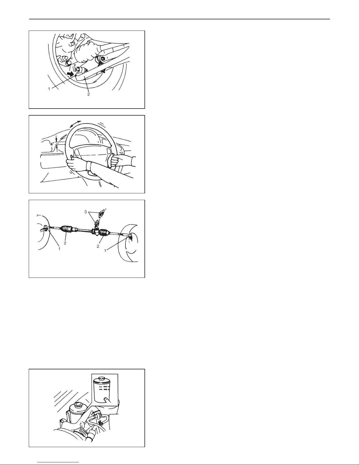
1. Ball joint stud dust seal (boot)
2. Suspension arm
1. Tie-rod end boot
2. Steering gear case boot
3. Universal joint
0B-16 MAINTENANCE AND LUBRICATION
D Check front and rear suspension systems for damaged, loose or
missing parts; also for parts showing signs of wear or lack of lubrication.
Repair or replace defective parts, if any.
D Check front suspension arm ball joint stud dust seals for leakage,
detachment, tear or any other damage.
Replace defective boot, if any.
ITEM 6-5
Steering System Inspection
1) Check steering wheel for play and rattle, holding vehicle straight
on ground.
Steering wheel play “a”: 0 – 30 mm (0 – 1.1 in.)
2) Check steering linkage for looseness and damage. Repair or replace defective parts, if any.
3) Check boots of steering linkage and steering gear case for damage (leaks, detachment, tear, etc.). If damage is found, replace
defective boot with new one.
4) Check universal joints of steering shaft for rattle and damage. If
rattle or damage is found, replace defective part with a new one.
ITEM 6-6
Power Steering (P/S) System Inspection (if equipped)
1) Visually check power steering system for fluid leakage and hose
for damage and deterioration.
Repair or replace defective parts, if any.
2) With engine stopped, check fluid level indicated on fluid tank,
which should be between MAX and MIN marks. If it is lower than
MIN, fill fluid up to MAX mark.
NOTE
D Be sure to use specified P / S fluid.
D Fluid level should be checked when fluid is cool.
3) Visually check pump drive belt for cracks and wear.
4) Check belt for tension, referring to item 1-1 in this section.
If necessary, adjust or replace.
Page 47
2WD
4WD
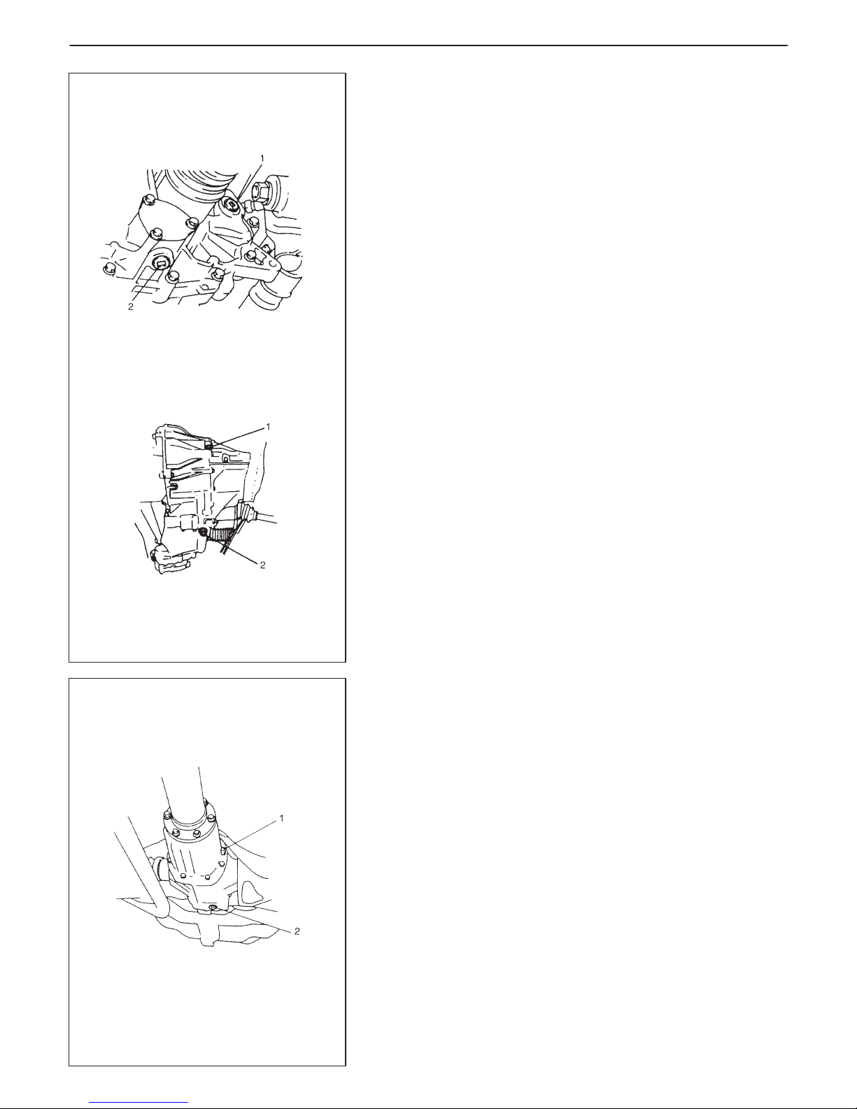
1. Oil filler / level plug
2. Oil drain plug
MAINTENANCE AND LUBRICATION 0B-17
ITEM 6-7
Manual Transmission Oil Inspection and Change
[Inspection]
1) Inspect transmission case for evidence of oil leakage.
Repair leaky point if any.
2) Make sure that vehicle is placed level for oil level check.
3) Remove oil level plug of transmission.
4) Check oil level.
Oil level can be checked roughly by means of filler/level plug
hole. That is, if oil flows out of level plug hole or if oil level is found
up to hole when level plug is removed, oil is properly filled.
If oil is found insufficient, pour specified oil up to level hole.
For specified oil, refer to description of oil change under ON-VEHICLE SERVICE in SECTION 7A or 7A1.
5) Tighten level plug to specified torque.
[Change]
1) Place the vehicle level and drain oil by removing drain plug.
2) Apply sealant to drain plug and tighten drain plug to specified
torque.
3) Pour specified oil up to level hole.
4) Tighten filler plug to specified torque.
For recommended oil, its amount and tightening torque data, refer to ON-VEHICLE SERVICE of SECTION 7A or 7A1.
ITEM 6-8
Rear Differential Oil Inspection and Change
(4WD vehicle only)
[Inspection]
1) Inspect rear differential case for evidence of oil leakage.
Repair leaky point, if any.
2) Make sure that the vehicle is placed level for oil level check.
3) Remove level plug (1) of differential. Oil level can be checked
roughly by means of level plug hole.
That is, if oil flows out of level plug hole or if oil level is found up
to hole when level plug is removed, oil is properly filled.
If oil is found insufficient, pour specified amount of specified oil
as given in SECTION 7E.
4) Tighten it to specified torque.
[Change]
Place the vehicle level and drain oil by removing drain plug (2). Pour
specified amount of specified oil, tighten drain plug and filler plug
to specified torque, referring to ON-VEHICLE SERVICE in SECTION 7E.
Page 48

1. Oil level gauge
2. FULL HOT mark
3. LOW HOT mark
4. FULL COLD mark
5. LOW COLD mark
1. Drain plug
0B-18 MAINTENANCE AND LUBRICATION
ITEM 6-9
Automatic Transmission
[Fluid level inspection]
1) Inspect transmission case for evidence of fluid leakage.
Repair leaky point, if any.
2) Make sure that vehicle is placed level for fluid level check.
3) Check fluid level.
For fluid level checking procedure, refer to ON-VEHICLE SERVICE in SECTION 7B and be sure to perform it under specified
conditions. If fluid level is low, replenish specified fluid.
[Fluid change]
1) Perform steps 1) and 2) of above Fluid Level Inspection.
2) Change fluid. For its procedure, refer to ON-VEHICLE SERVICE in SECTION 7B.
CAUTION:
Use of specified fluid is absolutely necessary.
[Fluid cooler hose change]
Replace inlet and outlet hoses (1) of cooler hose and their clamps.
For replacement procedure, refer to ON-VEHICLE SERVICE in
SECTION 7B.
Page 49

“A”: Oil point
1. Upper hinge
2. Lower hinge
3. Door
4. Body
MAINTENANCE AND LUBRICATION 0B-19
ITEM 6-10
All Latches, Hinges and Locks Inspection
Doors
Check that each door of front, rear and back doors opens and
closes smoothly and locks securely when closed.
If any malfunction is found, lubricate hinge and latch or repair door
lock system.
Engine hood
Check that secondary latch operates properly (check that secondary latch keeps hood from opening all the way even when pulling
hood release handle inside vehicle.). Also check that hood opens
and closes smoothly and properly and hood locks securely when
closed.
If any malfunction is found, lubricate hinge and latch, or repair hood
lock system.
Page 50

0B-20 MAINTENANCE AND LUBRICATION
FINAL INSPECTION
Seats
Check that seat slides smoothly and locks securely at
any position. Also check that reclining mechanism of
front seat back allows it to be locked at any angle.
Seat Belt
Inspect belt system including webbing, buckles, latch
plates, retractors and anchors for damage or wear.
If “REPLACE BELT” label on belt is visible, replace
belt.
Check that seat belt is securely locked.
Battery Electrolyte Level Check
Check that the electrolyte level of all battery cells is
between the upper and lower level lines on the case.
If battery is equipped with built-in indicator, check battery condition by the indicator.
Accelerator Pedal Operation
Check that pedal operates smoothly without getting
caught or interfered by and other part.
Engine Start
Check engine start for readiness.
On automatic transmission vehicles, try to start the
engine in each gear. The starter should crank only in
“P” (Park) or “N” (Neutral).
On manual transmission vehicles, place the shift lever in “Neutral,” depress clutch pedal fully and try to
start.
Exhaust System Check
Check for leakage, cracks or loose supports.
Clutch (For manual transmission)
Check for the following.
D Clutch is completely released when depressing
clutch pedal.
D No slipping clutch occurs when releasing pedal and
accelerating.
D Clutch itself is free from any abnormal condition.
Gearshift or Select Lever (Transmission)
Check gear shift or select lever for smooth shifting to
all positions and for good performance of transmission in any position.
With automatic transmission equipped vehicle, also
check that shift indicator indicates properly according
to which position select lever is shifted to.
CAUTION:
With automatic transmission equipped vehicle, make sure that vehicle is at complete
stop when shifting select lever to “P” range
position and release all brakes.
Brake
[Foot brake]
Check the following;
D that brake pedal has proper travel,
D that brake works properly,
D that it is free from noise,
D that vehicle does not pull to one side when brake is
applied,
D and that brake does not drag.
WARNING:
When carrying out road tests, select a safe
place where no man or no running vehicle is
seen so as to prevent any accident.
WARNING:
Before performing the following check, be
sure to have enough room around the vehicle.
Then, firmly apply both the parking brake and
the regular brakes. Do not use the accelerator
pedal. If the engine starts, be ready to turn off
the ignition promptly. Take these precautions
because the car could move without warning
and possibly cause personal injury or property damage.
Page 51

MAINTENANCE AND LUBRICATION 0B-21
[Parking brake]
Check that lever has proper travel.
Check to ensure that parking brake is fully effective
when the vehicle is stopped on the safe slope and
brake lever is pulled all the way.
Steering
D Check to ensure that steering wheel is free from in-
stability, or abnormally heavy feeling.
D Check that the vehicle does not wander or pull to
one side.
Engine
D Check that engine responds readily at all speeds.
D Check that engine is free from abnormal noise and
abnormal vibration.
Body, Wheels and Power Transmitting System
Check that body, wheels and power transmitting system are free from abnormal noise and abnormal
vibration or any other abnormal condition.
Meters and Gauge
Check that speedometer, odometer, fuel meter, temperature gauge, etc. are operating accurately.
Lights
Check that all lights operate properly.
Windshield Defroster
Periodically check that air comes out from defroster
outlet when operating heater or air conditioning.
Set fan switch lever to “HI” position and mode lever to
defroster position for this check.
WARNING:
With vehicle parked on a fairly steep slope,
make sure nothing is in the way downhill to
avoid any personal injury or property damage.
Be prepared to apply regular brake quickly
even if vehicle should start to move.
RECOMMENDED FLUIDS AND LUBRICANTS
Engine oil SE, SF, SG, SH or SJ (Refer to engine oil viscosity chart in item 1-4.)
Engine coolant Ethylene-glycol base coolant (“Antifreeze /Anticorrosion coolant”)
Brake fluid DOT3
Manual transmission oil See SECTION 7A
Rear differential oil See SECTION 7E
Automatic transmission fluid An equivalent of DEXRONR-IIE or DEXRONR-III
Power steering fluid See material table on SECTION 3B1
Door hinges Engine oil
Engine hood latch Engine oil
Key lock cylinder Spray lubricant
Page 52

6
ENGINE GENERAL INFORMATION AND DIAGNOSIS (TBI FOR G10) 6-1
GENERAL INFORMATION 6- 3. . . . . . . . . . . . . .
Statement on Cleanliness and Care 6- 3. . . . .
General Information on Engine Service 6- 3. .
Precaution on Fuel System Service 6- 4. . . . .
Fuel Pressure Relief Procedure 6- 5. . . . . . . .
Fuel Leakage Check Procedure 6- 5. . . . . . . .
ENGINE DIAGNOSIS 6- 6. . . . . . . . . . . . . . . . . . .
General Description 6- 6. . . . . . . . . . . . . . . . . . .
On-Board Diagnostic System 6- 6. . . . . . . . . .
Precaution in Diagnosing Trouble 6- 9. . . . . . .
Engine Diagnostic Flow Table 6-10. . . . . . . . . .
Customer Problem Inspection From 6-12. . . . .
Malfunction Indicator Lamp Check 6-13. . . . . .
Diagnostic Trouble Code Check 6-13. . . . . . . .
SECTION 6
ENGINE GENERAL INFORMATION
AND DIAGNOSIS
(TBI FOR G10)
WARNING:
For vehicles equipped with Supplemental Restraint (Air Bag) System:
D Service on and around the air bag system components or wiring must be performed only by an autho-
rized SUZUKI dealer. Refer to “Air Bag System Components and Wiring Location View” under “General Description” in air bag system section in order to confirm whether you are performing service on
or near the air bag system components or wiring. Please observe all WARNINGS and “Service Precautions” under “On-Vehicle Service” in air bag system section before performing service on or around
the air bag system components or wiring. Failure to follow WARNINGS could result in unintentional
activation of the system or could render the system inoperative. Either of these two conditions may
result in severe injury.
D Technical service work must be started at least 90 seconds after the ignition switch is turned to the
“LOCK” position and the negative cable is disconnected from the battery. Otherwise, the system may
be activated by reserve energy in the Sensing and Diagnostic Module (SDM).
ENGINE GENERAL INFORMATION AND DIAGNOSIS (TBI for G10) 6-1. . . . . . . . . . . . . . . . . . . . . . . . . . . . .
ENGINE GENERAL INFORMATION AND DIAGNOSIS (SFI for G13) 6-1-1. . . . . . . . . . . . . . . . . . . . . . . . . . . . .
ENGINE MECHANICAL (G10) 6A-1. . . . . . . . . . . . . . . . . . . . . . . . . . . . . . . . . . . . . . . . . . . . . . . . . . . . . . . . . . . . . . .
ENGINE MECHANICAL (G13 1 cam 16 valves) 6A1-1. . . . . . . . . . . . . . . . . . . . . . . . . . . . . . . . . . . . . . . . . . . . . . .
ENGINE COOLING 6B-1. . . . . . . . . . . . . . . . . . . . . . . . . . . . . . . . . . . . . . . . . . . . . . . . . . . . . . . . . . . . . . . . . . . . . . . . .
ENGINE FUEL 6C-1. . . . . . . . . . . . . . . . . . . . . . . . . . . . . . . . . . . . . . . . . . . . . . . . . . . . . . . . . . . . . . . . . . . . . . . . . . . . .
ENGINE AND EMISSION CONTROL SYSTEM (TBI for G10) 6E1-1. . . . . . . . . . . . . . . . . . . . . . . . . . . . . . . . . . . .
ENGINE AND EMISSION CONTROL SYSTEM (SFI for G13) 6E2-1. . . . . . . . . . . . . . . . . . . . . . . . . . . . . . . . . . . .
IGNITION SYSTEM (G10 ENGINE) 6F-1. . . . . . . . . . . . . . . . . . . . . . . . . . . . . . . . . . . . . . . . . . . . . . . . . . . . . . . . . . .
IGNITION SYSTEM (G13 ENGINE) 6F1-1. . . . . . . . . . . . . . . . . . . . . . . . . . . . . . . . . . . . . . . . . . . . . . . . . . . . . . . . . . .
CRANKING SYSTEM 6G-1. . . . . . . . . . . . . . . . . . . . . . . . . . . . . . . . . . . . . . . . . . . . . . . . . . . . . . . . . . . . . . . . . . . . . . .
CHARGING SYSTEM 6H-1. . . . . . . . . . . . . . . . . . . . . . . . . . . . . . . . . . . . . . . . . . . . . . . . . . . . . . . . . . . . . . . . . . . . . .
EXHAUST SYSTEM 6K-1. . . . . . . . . . . . . . . . . . . . . . . . . . . . . . . . . . . . . . . . . . . . . . . . . . . . . . . . . . . . . . . . . . . . . . . .
NOTE:
For the descriptions for vehicle without warm up three way catalytic converter (WUTWC), refer to Section
6 and 6E1 of the Service Manual mentioned in the FOREWORD of this manual.
CONTENTS
Page 53

Diagnostic Trouble Code Clearance 6-14. . . . .
Diagnostic Trouble Code Table 6-15. . . . . . . . .
Fail-safe Table 6-18. . . . . . . . . . . . . . . . . . . . . . .
Visual Inspection 6-19. . . . . . . . . . . . . . . . . . . . .
Engine Basic Inspection 6-20. . . . . . . . . . . . . . .
Engine Diagnosis Table 6-22. . . . . . . . . . . . . . .
Scan Tool Data 6-29. . . . . . . . . . . . . . . . . . . . . . .
Scan Tool Data Definitions 6-31. . . . . . . . . . . . .
Inspection of ECM (PCM) and Its Circuits 6-33
Voltage Check 6-33. . . . . . . . . . . . . . . . . . . . .
Resistance Check 6-37. . . . . . . . . . . . . . . . . .
Component Location 6-38. . . . . . . . . . . . . . . . . .
Table A-1 MIL Circuit Check
(Lamp does not come on) 6-39. . . . . . . . . . . .
Table A-2 MIL Circuit Check
(Lamp remains ON) 6-40. . . . . . . . . . . . . . . . . .
Table A-3 ECM (PCM) Power and Ground
Circuit Check 6-42. . . . . . . . . . . . . . . . . . . . . . .
DTC P0105 MAP Circuit Malfunction 6-44. . . .
DTC P0110 IAT Circuit Malfunction 6-46. . . . .
DTC P0115 ECT Circuit Malfunction 6-48. . . .
DTC P0120 Throttle Position Circuit
Malfunction 6-50. . . . . . . . . . . . . . . . . . . . . . . . .
DTC P0121 Throttle Position Circuit
Range/Performance Problem 6-52. . . . . . . . .
DTC P0130 HO2S Circuit Malfunction
(Sensor-1) 6-54. . . . . . . . . . . . . . . . . . . . . . . . . .
DTC P0133 HO2S Circuit Slow
Response (Sensor-1) 6-56. . . . . . . . . . . . . . . .
DTC P0135 HO2S Heater Circuit
Malfunction (Sensor-1) 6-57. . . . . . . . . . . . . . .
DTC P0136 HO2S Circuit Malfunction
(Sensor-2) 6-59. . . . . . . . . . . . . . . . . . . . . . . . . .
DTC P0141 HO2S Heater Circuit
Malfunction (Sensor-2) 6-62. . . . . . . . . . . . . . .
DTC P0171 Fuel System Too Lean 6-64. . . . .
DTC P0172 Fuel System Too Rich 6-64. . . . . .
DTC P0300 Random Misfire Detected 6-68. . .
DTC P0301 Cylinder 1 Misfire Detected 6-68.
DTC P0302 Cylinder 2 Misfire Detected 6- 68.
DTC P0303 Cylinder 3 Misfire Detected 6- 68.
DTC P0335 CKP Sensor Circuit
Malfunction 6- 72. . . . . . . . . . . . . . . . . . . . . . . . .
DTC P0340 CMP Sensor Circuit
Malfunction 6- 74. . . . . . . . . . . . . . . . . . . . . . . . .
DTC P0420 Catalyst System Efficiency
Below Threshold 6- 76. . . . . . . . . . . . . . . . . . . .
DTC P0443 Purge Control Valve Circuit
Malfunction 6- 79. . . . . . . . . . . . . . . . . . . . . . . . .
DTC P0480 Radiator Fan Control
System Malfunction 6- 80. . . . . . . . . . . . . . . . . .
DTC P0500 Vehicle Speed Sensor
Malfunction (M/T) 6- 82. . . . . . . . . . . . . . . . . . .
DTC P0500 Vehicle Speed Sensor
Malfunction (A/T) 6- 84. . . . . . . . . . . . . . . . . . .
DTC P0505 Idle Control System
Malfunction 6- 86. . . . . . . . . . . . . . . . . . . . . . . . .
DTC P0510 Closed Throttle Position
Switch Malfunction 6- 88. . . . . . . . . . . . . . . . . .
DTC P0601 Internal Control Module
Memory Check Sum Error 6- 89. . . . . . . . . . . .
DTC P1250 EFE Heater Circuit
Malfunction 6- 90. . . . . . . . . . . . . . . . . . . . . . . . .
DTC P1450 Barometric Pressure
Sensor Low/High Input 6- 92. . . . . . . . . . . . . .
DTC P1451 Barometric Pressure Sensor
Performance Problem 6- 92. . . . . . . . . . . . . . . .
DTC P1500 Engine Starter Signal
Circuit Malfunction 6- 93. . . . . . . . . . . . . . . . . . .
DTC P1510 ECM (PCM) Back-up Power
Supply Malfunction 6- 94. . . . . . . . . . . . . . . . . .
Table B-1 Fuel Injector Circuit Check 6- 96. . . .
Table B-2 Fuel Pump and Its Circuit
Check 6- 98. . . . . . . . . . . . . . . . . . . . . . . . . . . . .
Table B-3 Fuel Pressure Check 6-100. . . . . . . . .
Table B-4 A/C Signal Circuits Check 6-102. . . .
Table B-5 Power Steering Pressure
Switch Signal Circuit Check 6-103. . . . . . . . . . .
SPECIAL TOOL 6-104. . . . . . . . . . . . . . . . . . . . . . .
6-2 ENGINE GENERAL INFORMATION AND DIAGNOSIS (TBI FOR G10)
Page 54

1. No.1 cylinder
2. No.2 cylinder
3. No.3 cylinder
1
2
3
ENGINE GENERAL INFORMATION AND DIAGNOSIS (TBI FOR G10) 6-3
GENERAL INFORMATION
STATEMENT ON CLEANLINESS AND CARE
An automobile engine is a combination of many machined, honed,
polished and lapped surfaces with tolerances that are measured in
the thousands of an millimeter (ten thousands of an inch).
Accordingly, when any internal engine parts are serviced, care and
cleanliness are important.
Throughout this section, it should be understood that proper cleaning and protection of machined surfaces and friction areas is part
of the repair procedure. This is considered standard shop practice
even if not specifically stated.
D A liberal coating of engine oil should be applied to friction areas
during assembly to protect and lubricate the surfaces on initial operation.
D Whenever valve train components, pistons, piston rings, con-
necting rods, rod bearings, and crankshaft journal bearings are
removed for service, they should be retained in order.
At the time of installation, they should be installed in the same
locations and with the same mating surfaces as when removed.
D Battery cables should be disconnected before any major work is
performed on the engine.
Failure to disconnect cables may result in damage to wire harness or other electrical parts.
D Throughout this manual, the four cylinders of the engine are iden-
tified by numbers; No.1 (1), No.2 (2) and No.3 (3) counted from
crankshaft pulley side to flywheel side.
GENERAL INFORMATION ON ENGINE SERVICE
THE FOLLOWING INFORMATION ON ENGINE SERVICE
SHOULD BE NOTED CAREFULLY, AS IT IS IMPORTANT IN PREVENTING DAMAGE, AND IN CONTRIBUTING TO RELIABLE ENGINE PERFORMANCE.
D When raising or supporting engine for any reason, do not use a
jack under oil pan. Due to small clearance between oil pan and
oil pump strainer, jacking against oil pan may cause it to be bent
against strainer resulting in damaged oil pick-up unit.
D It should be kept in mind, while working on engine, that 12-volt
electrical system is capable of violent and damaging short circuits.
When performing any work where electrical terminals can be
grounded, ground cable of the battery should be disconnected at
battery.
D Any time the air cleaner, throttle body or intake manifold is re-
moved, the intake opening should be covered. This will protect
against accidental entrance of foreign material which could follow
intake passage into cylinder and cause extensive damage when
engine is started.
Page 55
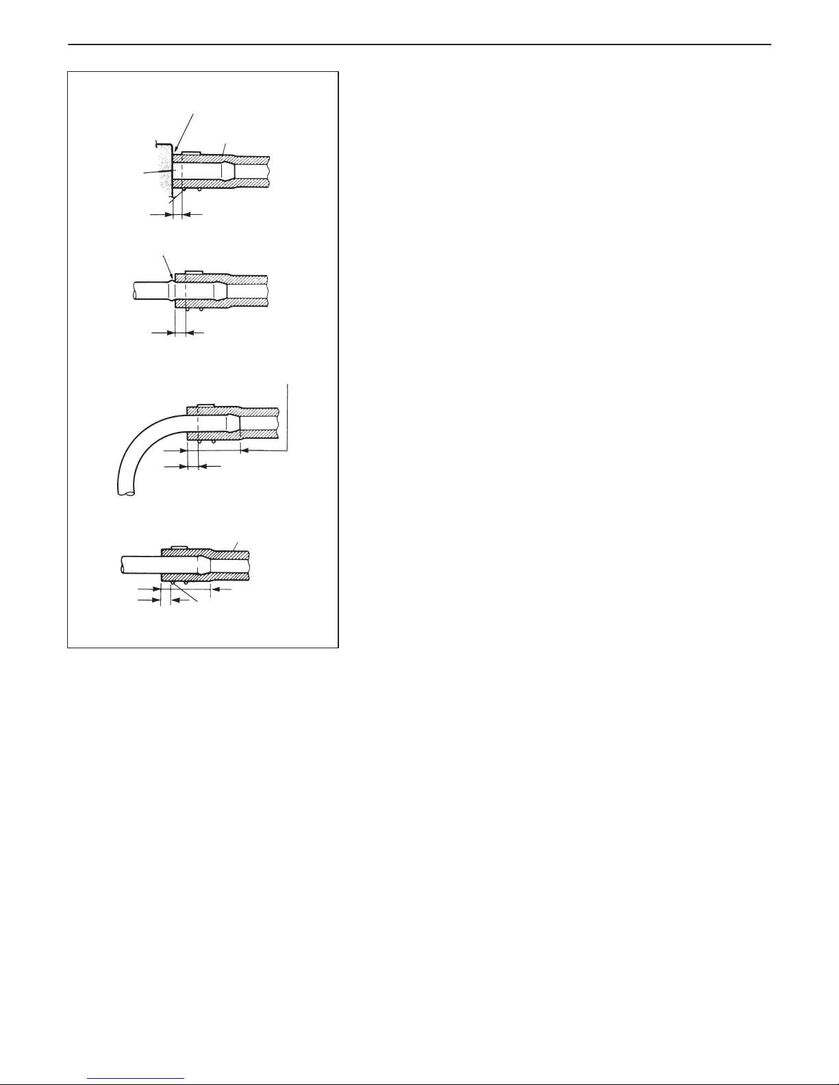
HOSE CONNECTION
Clamp securely at a position 3 to
7mm (0.12–0.27 in.) from hose end.
With short pipe, fit hose as far as it reaches pipe joint as
shown.
Hose
Pipe
Clamp
Clamps securely at a position
3 to 7 mm (0.12–0.27 in.)
from hose end.
With following type pipe, fit hose as far as its peripheral
projection as shown.
Clamp securely at a position
3 to 7 mm (0.12–0.27 in.)
from hose end.
With bent pipe, fit hose as its bent part as shown or till pipe
is about 20 to 30 mm (0.79–1.18 in.) into the hose.
Clamp securely at a
position 3 to 7 mm
(0.12–0.27 in.) from hose
end.
With straight pipe, fit hose till pipe is, about 20 to 30 mm
(0.79–1.18 in.) into the hose.
Hose
20 to 30 mm
(0.79–1.18 in.)
Clamp
6-4 ENGINE GENERAL INFORMATION AND DIAGNOSIS (TBI FOR G10)
PRECAUTION ON FUEL SYSTEM SERVICE
D Work must be done with no smoking, in a well-ventilated area and
away from any open flames.
D As fuel feed line (between fuel pump and fuel delivery pipe) is still
under high fuel pressure even after engine was stopped, loosening or disconnecting fuel feed line directly may cause dangerous
spout of fuel to occur where loosened or disconnected.
Before loosening or disconnecting fuel feed line, make sure to release fuel pressure according to “FUEL PRESSURE RELIEF
PROCEDURE”. A small amount of fuel may be released after the
fuel line is disconnected. In order to reduce the chance of personal injury, cover the fitting to be disconnected with a shop cloth. Put
that cloth in an approved container when disconnection is completed.
D Never run engine with fuel pump relay disconnected when engine
and exhaust system are hot.
D Fuel or fuel vapor hose connection varies with each type of pipe.
When reconnecting fuel or fuel vapor hose, be sure to connect
and clamp each hose correctly referring to left figure Hose Connection.
After connecting, make sure that it has no twist or kink.
D When installing injector or fuel delivery pipe, lubricate its O-ring
with spindle oil or gasoline.
D When connecting fuel pipe flare nut, first tighten flare nut by hand
and then tighten it to specified torque.
Page 56

ENGINE GENERAL INFORMATION AND DIAGNOSIS (TBI FOR G10) 6-5
FUEL PRESSURE RELIEF PROCEDURE
CAUTION:
This work must not be done when engine is hot. If done so,
it may cause adverse effect to catalyst.
After making sure that engine is cold, release fuel pressure as follows.
1) Place transmission gear shift lever in “Neutral” (Shift selector lever to “P” range for A/T model), set parking brake, and block
drive wheels.
2) Remove relay box cover.
3) Disconnect fuel pump relay (1) from relay box (2).
4) Remove fuel filler cap to release fuel vapor pressure in fuel tank
and then reinstall it.
5) Start engine and run it till it stops for lack of fuel. Repeat cranking
engine 2-3 times for about 3 seconds each time to dissipate fuel
pressure in lines. Fuel connections are now safe for servicing.
6) Upon completion of servicing, connect fuel pump relay to relay
box and install relay box cover.
FUEL LEAKAGE CHECK PROCEDURE
After performing any service on fuel system, check to make sure
that there are no fuel leakages as follows.
1) Turn ON ignition switch for 2 seconds (to operate fuel pump) and
then turn it OFF.
Repeat this (ON and OFF) 3 or 4 times and apply fuel pressure
to fuel line. (till fuel pressure is felt by hand placed on fuel feed
hose.)
2) In this state, check to see that there are no fuel leakages from
any part of fuel system.
Page 57

6-6 ENGINE GENERAL INFORMATION AND DIAGNOSIS (TBI FOR G10)
ENGINE DIAGNOSIS
GENERAL DESCRIPTION
This vehicle is equipped with an engine and emission control system which are under control of ECM (PCM).
The engine and emission control system in this vehicle are controlled by ECM (PCM). ECM (PCM) has an OnBoard Diagnostic system which detects a malfunction in this system and abnormality of those parts that influence
the engine exhaust emission. When diagnosing engine troubles, be sure to have full understanding of the outline
of “On-Board Diagnostic System” and each item in “Precaution in Diagnosing Trouble” and execute diagnosis ac-
cording to “ENGINE DIAGNOSTIC FLOW TABLE”.
There is a close relationship between the engine mechanical, engine cooling system, ignition system, exhaust system, etc. and the engine and emission control system in their structure and operation. In case of an engine trouble,
even when the malfunction indicator lamp (MIL) doesn’t turn ON, it should be diagnosed according to this flow table.
ON-BOARD DIAGNOSTIC SYSTEM
ECM (PCM) in this vehicle has following functions.
D When the ignition switch is turned ON with the engine at a stop,
malfunction indicator lamp (MIL) (1) turns ON to check the bulb
of the malfunction indicator lamp (1).
D When ECM (PCM) detects a malfunction which gives an adverse
effect to vehicle emission while the engine is running, it makes the
malfunction indicator lamp (1) in the meter cluster of the instrument panel turn ON or flash (flashing only when detecting a misfire which can cause damage to the catalyst) and stores the malfunction area in its memory.
(If it detects that continuously 3 driving cycles are normal after detecting a malfunction, however, it makes MIL (1) turn OFF although DTC stored in its memory will remain.)
D As a condition for detecting a malfunction in some areas in the
system being monitored by ECM (PCM) and turning ON the malfunction indicator lamp (1) due to that malfunction, 2 driving cycle
detection logic is adopted to prevent erroneous detection.
D When a malfunction is detected, engine and driving conditions
then are stored in ECM (PCM) memory as freeze frame data. (For
the details, refer to description on Freeze frame data.)
D It is possible to communicate by using not only SUZUKI scan tool
(Tech-1) (2) but also generic scan tool. (Diagnostic information
can be accessed by using a scan tool.)
Page 58

An Example of Freeze Frame Data
1. Trouble Code P0102 (1st)
2. Engine Speed 782 RPM
3. Eng Cool Tmp. 80_C
4. Vehicle Spd. 0 km/h
5. MAP Sensor 39 kPa
6. St. Term FT1 – 0.8% Lean
7. Lg. Term FT1 – 1.6% Lean
8. Fuel 1 Stat. Closed Loop
9. Fuel 2 Stat. Not used
10. Load value 25.5%
1st, 2nd or 3rd in parentheses here represents which
position in the order the malfunction is detected.
ENGINE GENERAL INFORMATION AND DIAGNOSIS (TBI FOR G10) 6-7
Warm-up Cycle
A warm-up cycle means sufficient vehicle operation such that the
coolant temperature has risen by at least 22_C (40_F) from engine
starting and reaches a minimum temperature of 70_C (160_F).
Driving Cycle
A “Driving Cycle” consists of engine startup, driving mode where a
malfunction would be detected if present and engine shutoff.
2 Driving Cycles Detection Logic
The malfunction detected in the first driving cycle is stored in ECM
(PCM) memory (in the form of pending DTC and freeze frame data)
but the malfunction indicator lamp does not light at this time. It lights
up at the second detection of same malfunction also in the next driving cycle.
Pending DTC
Pending DTC means a DTC detected and stored temporarily at 1
driving cycle of the DTC which is detected in the 2 driving cycles
detection logic.
Freeze Frame Data
ECM (PCM) stores the engine and driving conditions (in the from
of data as shown at the left) at the moment of the detection of a malfunction in its memory. This data is called “Freeze frame data”.
Therefore, it is possible to know engine and driving conditions (e.g.,
whether the engine was warm or not, where the vehicle was running
or stopped, where air/fuel mixture was lean or rich) when a malfunction was detected by checking the freeze frame data. Also,
ECM (PCM) has a function to store each freeze frame data for three
different malfunctions in the order as the malfunction is detected.
Utilizing this function, it is possible to know the order of malfunctions
that have been detected. Its use is helpful when rechecking or diagnosing a trouble.
Priority of freeze frame data:
ECM (PCM) has 4 frames where the freeze frame data can be
stored. The first frame stores the freeze frame data of the malfunction which was detected first. However, the freeze frame data
stored in this frame is updated according to the priority described
below. (If malfunction as described in the upper square “1” below
is detected while the freeze frame data in the lower square “2” has
been stored, the freeze frame data “2” will be updated by the freeze
frame data “1”.)
PRIORITY
FREEZE FRAME DATA IN FRAME 1
1
Freeze frame data at initial detection of malfunction
among misfire detected (P0300-P0303), fuel
system too lean (P0171) and fuel system too rich
(P0172)
2
Freeze frame data when a malfunction other than
those in “1” above is detected
Page 59
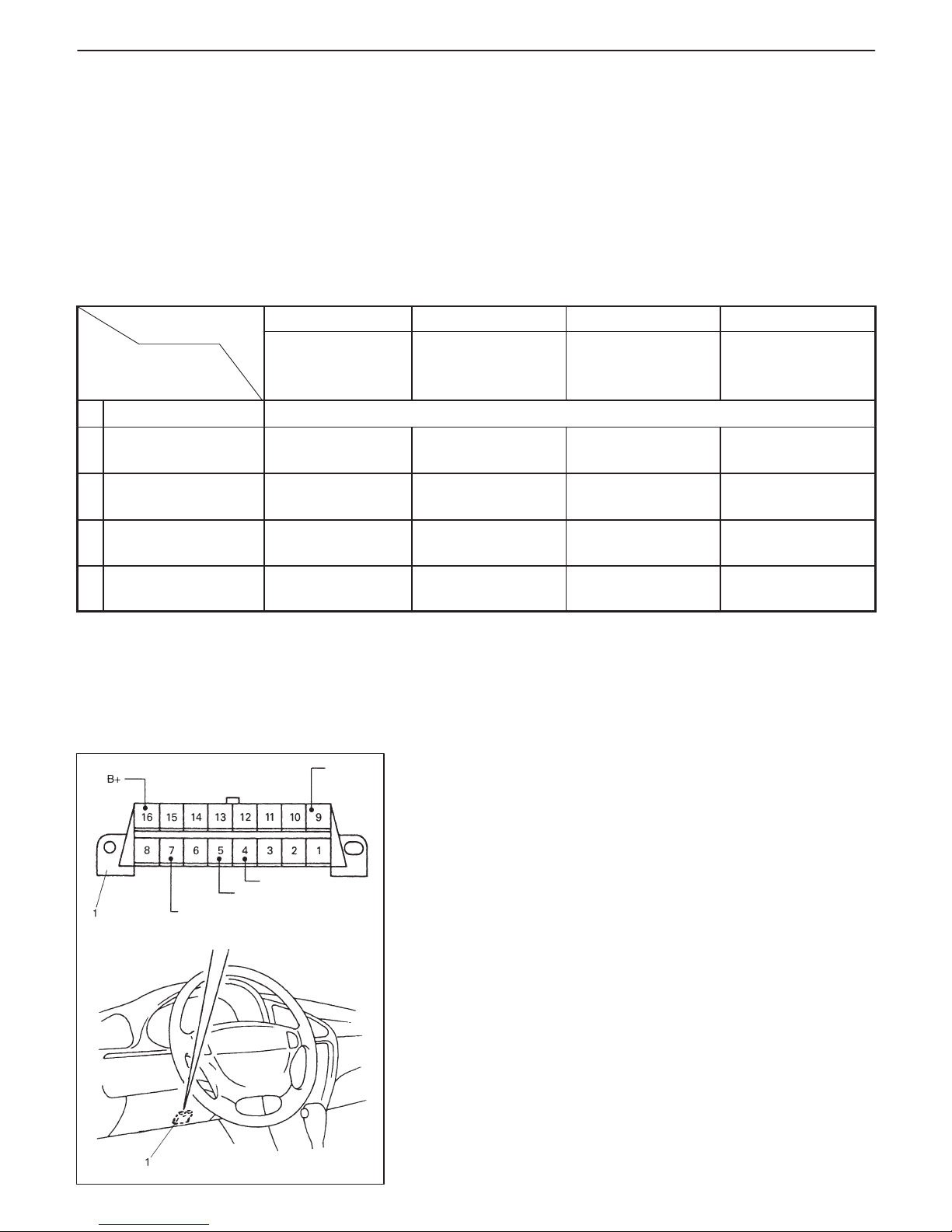
Body ground
ECM (PCM) ground
Serial data line
(K line of ISO 9141)
SUZUKI
serial data
line
6-8 ENGINE GENERAL INFORMATION AND DIAGNOSIS (TBI FOR G10)
In the 2nd through the 4th frames, the freeze frame data of each
malfunction is stored in the order as the malfunction is detected.
These data are not updated.
Shown in the table below are examples of how freeze frame data
are stored when two or more malfunctions are detected.
FRAME 1 FRAME 2 FRAME 3 FRAME 4
FRAME
MALFUNCTION
DETECTED ORDER
FREEZE FRAME
DATA
to be updated
1st FREEZE
FRAME DATA
2nd FREEZE
FRAME DATA
3rd FREEZE
FRAME DATA
No malfunction No freeze frame data
1
P0400 (EGR)
detected
Data at P0400
detection
Data at P0400
detection
– –
2
P0171 (Fuel
system) detected
Data at P0171
detection
Data at P0400
detection
Data at P0171
detection
–
3
P0300 (Misfire)
detected
Data at P0171
detection
Data at P0400
detection
Data at P0171
detection
Data at P0300
detection
4
P0301 (Misfire)
detected
Data at P0171
detection
Data at P0400
detection
Data at P0171
detection
Data at P0300
detection
Freeze frame data clearance:
The freeze frame data is cleared at the same time as clearance of
diagnostic trouble code (DTC).
Data Link Connector (DLC)
DLC (1) is in compliance with SAEJ1962 in its installation position,
the shape of connector and pin assignment.
Serial data line (K line of ISO 9141) is used for SUZUKI scan tool
(Tech-1) or generic scan tool to communicate with ECM (PCM).
SUZUKI serial data line is used for SUZUKI scan tool (Tech-1) to
communicate with ABS control module and air bay SDM.
Page 60

ENGINE GENERAL INFORMATION AND DIAGNOSIS (TBI FOR G10) 6-9
PRECAUTION IN DIAGNOSING TROUBLE
D Don’t disconnect couplers from ECM (PCM), battery cable from
battery, ECM (PCM) ground wire harness from engine or main
fuse before confirming diagnostic information (DTC, freeze frame
data, etc.) stored in ECM (PCM) memory. Such disconnection will
erase memorized information in ECM (PCM) memory.
D Diagnostic information stored in ECM (PCM) memory can be
cleared as well as checked by using SUZUKI scan tool (Tech-1)
or generic scan tool. Before using scan tool, read its Operator’s
(Instruction) Manual carefully to have good understanding as to
what functions are available and how to use it.
D Priorities for diagnosing troubles.
If two or more DTCs are stored, proceed to the flow table of the
DTC which has detected earliest in the order and follow the
instruction in that table.
If no instructions are given, troubleshoot diagnostic trouble codes
according to the following priorities.
1. Diagnostic trouble codes (DTCs) other than DTC P0171/
P0172 (Fuel system too lean/too rich) and DTC P0300/
P0301/P0302/ P0303 (Misfire detected)
2. DTC P0171/P0172 (Fuel system too lean / too rich)
3. DTC P0300/P0301 / P0302 / P0303 (Misfire detected)
D Be sure to read “Precautions for Electrical Circuit Service” in Sec-
tion 0A before inspection and observe what is written there.
D ECM (PCM) Replacement
When substituting a known-good ECM (PCM), check for following
conditions. Neglecting this check may cause damage to a knowngood ECM (PCM).
– Resistance value of all relays, actuators is as specified respec-
tively.
– MAP sensor and TP sensor are in good condition and none of
power circuits of these sensors is shorted to ground.
Page 61

6-10 ENGINE GENERAL INFORMATION AND DIAGNOSIS (TBI FOR G10)
ENGINE DIAGNOSTIC FLOW TABLE
Refer to the following pages for the details of each step.
STEP
ACTION YES NO
1 Customer Complaint Analysis
1) Perform customer complaint analysis referring to the
next page.
Was customer complaint analysis performed?
Go to Step 2. Perform customer
complaint analysis.
2 Diagnostic Trouble Code (DTC) and Freeze Frame Data
Check, Record and Clearance
1) Check for DTC (including pending DTC) referring to
the next page.
Is there any DTC(s)?
1) Print DTC and
freeze frame data
or write them
down and clear
them by referring
to “DTC
Clearance”
section.
2) Go to Step 3.
Go to Step 4.
3 Visual Inspection
1) Perform visual inspection referring to the next page.
Is there any faulty condition?
1) Repair or replace
malfunction part.
2) Go to Step 11.
Go to Step 5.
4 Visual Inspection
1) Perform visual inspection referring to the next page.
Is there any faulty condition?
Go to Step 8.
5 Trouble Symptom Confirmation
1) Confirm trouble symptom referring to the next page.
Is trouble symptom identified?
Go to Step 6. Go to Step 7.
6 Rechecking and Record of DTC / Freeze Frame Data
1) Recheck for DTC and freeze frame data referring to
“DTC Check” section.
Is there any DTC(s)?
Go to Step 9.
Go to Step 8.
7 Rechecking and Record of DTC / Freeze Frame Data
1) Recheck for DTC and freeze frame data referring to
“DTC Check” section.
Is there any DTC(s)?
Go to Step 10.
8 Engine Basic Inspection and Engine Diag. Table
1) Check and repair according to “Engine Basic Check”
and “Engine Diag. Table” section.
Are check and repair complete?
Go to Step 11. 1) Check and repair
malfunction
part(s).
2) Go to Step 11.
9 Trouble shooting for DTC
1) Check and repair according to applicable DTC diag.
flow table.
Are check and repair complete?
10 Check for Intermittent Problems
1) Check for intermittent problems referring to the next
page.
Is there any faulty condition?
1) Repair or replace
malfunction
part(s).
2) Go to Step 11.
Go to Step 11.
11 Final Confirmation Test
1) Clear DTC if any.
2) Perform final confirmation test referring to the next
page.
Is there any problem symptom, DTC or abnormal
condition?
Go to Step 6. End.
Page 62

ENGINE GENERAL INFORMATION AND DIAGNOSIS (TBI FOR G10) 6-11
1. CUSTOMER COMPLAINT ANALYSIS
Record details of the problem (failure, complaint) and how it occurred as described by the customer. For this
purpose, use of such an inspection form will facilitate collecting information to the point required for proper
analysis and diagnosis.
2. DIAGNOSTIC TROUBLE CODE (DTC) / FREEZE FRAME DATA CHECK, RECORD AND
CLEARANCE
First, check DTC (including pending DTC), referring to “DTC check” section. If DTC is indicated, print it and
freeze frame data or write them down and then clear them by referring to “DTC clearance” section. DTC indicates malfunction that occurred in the system but does not indicate whether it exists now or it occurred in the
past and the normal condition has been restored now. To check which case applies, check the symptom in
question according to Step 4 and recheck DTC according to Step 5.
Attempt to diagnose a trouble based on DTC in this step only or failure to clear the DTC in this step will lead
to incorrect diagnosis, trouble diagnosis of a normal circuit or difficulty in troubleshooting.
NOTE:
If only Automatic transmission DTCs (P0705/P0720/ P0753 / P0758 /P0751/P0756) or Immobilizer
DTCs (P1620 – P1623) are indicated in this step, perform trouble diagnosis according to “Diagnosis”
in Section 7B or Section 8G.
3. and 4. VISUAL INSPECTION
As a preliminary step, be sure to perform visual check of the items that support proper function of the engine
referring to “Visual Inspection” section.
5. TROUBLE SYMPTOM CONFIRMATION
Based on information obtained in Step 1 Customer complaint analysis and Step 2 DTC/freeze frame data
check, confirm trouble symptoms. Also, reconfirm DTC according to “DTC Confirmation Procedure” described
in each DTC Diagnosis section.
6. and 7. RECHECKING AND RECORD OF DTC/FREEZE FRAME DATA
Refer to “DTC check” section for checking procedure.
8. ENGINE BASIC INSPECTION AND ENGINE DIAGNOSIS TABLE
Perform basic engine check according to the “Engine Basic Inspection Flow Table” first. When the end of the
flow table has been reached, check the parts of the system suspected as a possible cause referring to ENGINE
DIAGNOSIS FLOW TABLE and based on symptoms appearing on the vehicle (symptoms obtained through
steps of customer complaint analysis, trouble symptom confirmation and/or basic engine check) and repair
or replace faulty parts, if any.
9. TROUBLESHOOTING FOR DTC (See each DTC Diag. Flow Table)
Based on the DTC indicated in Step 5 and referring to the applicable DTC diag. flow table in this section, locate
the cause of the trouble, namely in a sensor, switch, wire harness, connector, actuator, ECM (PCM) or other
part and repair or replace faulty parts.
10. CHECK FOR INTERMITTENT PROBLEM
Check parts where an intermittent trouble is easy to occur (e.g., wire harness, connector, etc.), referring to
“INTERMITTENT AND POOR CONNECTION” in Section 0A and related circuit of DTC recorded in Step 2.
11. FINAL CONFIRMATION TEST
Confirm that the problem symptom has gone and the engine is free from any abnormal conditions. If what has
been repaired is related to the DTC, clear the DTC once, perform DTC confirmation procedure and confirm
that no DTC is indicated.
Page 63

6-12 ENGINE GENERAL INFORMATION AND DIAGNOSIS (TBI FOR G10)
CUSTOMER PROBLEM INSPECTION FORM (EXAMPLE)
User name: Model: VIN:
Date of issue: Date Reg. Date of problem: Mileage:
PROBLEM SYMPTOMS
j Difficult Starting
j No cranking
j No initial combustion
j No combustion
j Poor starting at
(jcold jwarm jalways)
j Other
j Poor Driveability
j Hesitation on acceleration
j Back fire /jAfter fire
j Lack of power
j Surging
j abnormal knocking
j Other
j Poor Idling
j Poor fast idle
j Abnormal idling speed
(jHigh jLow) ( r/min.)
j Unstable
j Hunting ( r / min. to r / min.)
j Other
j Engine Stall when
j Immediately after start
j Accel. pedal is depressed
j Accel. pedal is released
j Load is applied
j A/C jElectric load jP/S
j Other
j Other
j OTHERS:
VEHICLE/ENVIRONMENTAL CONDITION WHEN PROBLEM OCCURS
Environmental Condition
Weather
Temperature
Frequency
Road
jFair jCloudy jRain jSnow jAlways jOther
jHot jWarm jCool jCold ( _F/ _C) jAlways
jAlways jSometimes ( times/ day, month) jOnly once jUnder certain condition
jUrban jSuburb jHighway jMountainous (jUphill jDownhill) jTarmacadam jGravel
jOther
Vehicle Condition
Engine
condition
jCold jWarming up phase jWarmed up jAlways jOther at starting
jImmediately after start jRacing without load jEngine speed ( r/min.)
Vehicle
condition
During driving: jConstant speed jAccelerating jDecelerating
jRight hand corner jLeft hand corner jWhen shifting (Lever position ) jAt stop
jVehicle speed when problem occurs ( km/h, Mile/ h) jOther
Malfunction indicator
lamp condition
jAlways ON jSometimes ON jAlways OFF jGood condition
Diagnostic trouble
First check: jNo code jMalfunction code ( )
g
code
Second check: jNo code jMalfunction code ( )
NOTE:
The above form is a standard sample. It should be modified according to conditions characteristic of each
market.
Page 64
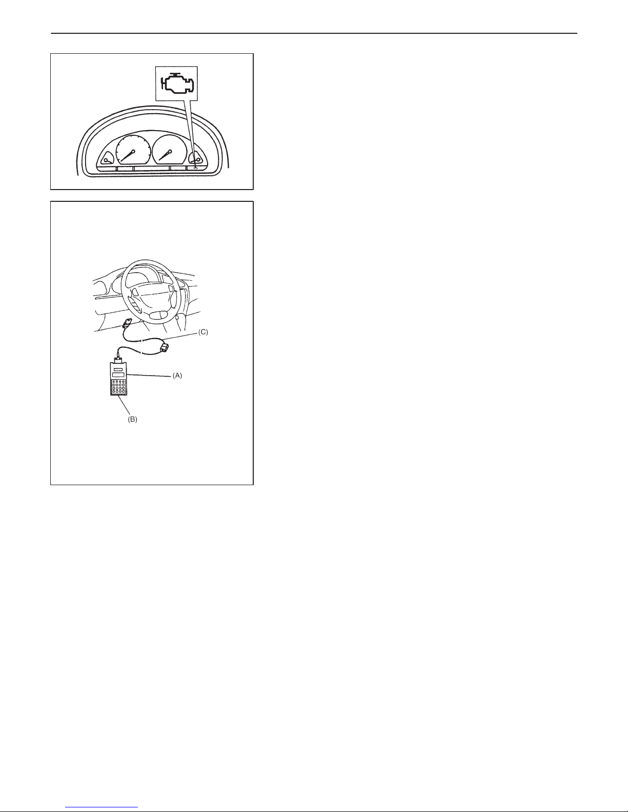
ENGINE GENERAL INFORMATION AND DIAGNOSIS (TBI FOR G10) 6-13
MALFUNCTION INDICATOR LAMP (MIL)
CHECK
1) Turn ON ignition switch (but the engine at stop) and check that
MIL lights.
If MIL does not light up (or MIL dims), go to “Diagnostic Flow
Table A-1” for troubleshooting.
2) Start engine and check that MIL turns OFF.
If MIL remains ON and no DTC is stored in ECM (PCM), go to
“Diagnostic Flow Table A-2” for troubleshooting.
DIAGNOSTIC TROUBLE CODE (DTC) CHECK
1) Prepare SUZUKI scan tool (Tech-1) or generic scan tool.
2) With ignition switch OFF, connect it to data link connector (DLC)
(1) located on underside of instrument panel at driver’s seat side.
Special Tool:
(A): SUZUKI scan tool
(B): Mass storage cartridge
(C): 16/14 pin DLC cable
3) Turn ignition switch ON and confirm that MIL lights.
4) Read DTC, pending DTC and freeze frame data according to
instructions displayed on scan tool and print it or write it down.
Refer to scan tool operator’s manual for further details.
If communication between scan tool and ECM (PCM) is not possible, check if scan tool is communicable by connecting it to
ECM (PCM) in another vehicle. If communication is possible in
this case, scan tool is in good condition. Then check data link
connector and serial data line (circuit) in the vehicle with which
communication was not possible.
5) After completing the check, turn ignition switch off and disconnect scan tool from data link connector.
Page 65

6-14 ENGINE GENERAL INFORMATION AND DIAGNOSIS (TBI FOR G10)
DIAGNOSTIC TROUBLE CODE (DTC)
CLEARANCE
1) Connect SUZUKI scan tool (Tech-1) or generic scan tool to data
link connector in the same manner as when making this connection for DTC check.
2) Turn ignition switch ON.
3) Erase DTC and pending DTC according to instructions displayed on scan tool. Refer to scan tool operator’s manual for further details.
4) After completing the clearance, turn ignition switch off and disconnect scan tool from data link connector.
NOTE:
DTC and freeze frame data stored in ECM (PCM) memory
are also cleared in following cases. Be careful not to clear
them before keeping their record.
D When power to ECM (PCM) is cut off (by disconnecting
battery cable, removing fuse or disconnecting ECM
(PCM) connectors for 30 sec. or longer)
D When the same malfunction (DTC) is not detected again
during 40 engine warm-up cycles.
Page 66

ENGINE GENERAL INFORMATION AND DIAGNOSIS (TBI FOR G10) 6-15
DIAGNOSTIC TROUBLE CODE (DTC) TABLE
DTC
NO.
DETECTING ITEM
DETECTING CONDITION
(DTC will set when detecting:)
MIL
P0105
Manifold absolute pressure
circuit malfunction
Low pressure-high vacuum-low voltage
(or MAP sensor circuit shorted to ground)
High pressure-low vacuum-high voltage
(or MAP sensor circuit open)
1 driving cycle
P0110
Intake air temp. circuit
malfunction
Intake air temp. circuit low input
Intake air temp. circuit high input
1 driving cycle
P0115
Engine coolant temp. circuit
malfunction
Engine coolant temp. circuit low input
Engine coolant temp. circuit high input
1 driving cycle
P0120
Throttle position circuit
malfunction
Throttle position circuit low input
Throttle position circuit high input
1 driving cycle
P0121
Throttle position circuit
performance problem
Poor performance of TP sensor 2 driving cycles
P0130
HO2S circuit malfunction
(Sensor-1)
Min. output voltage of HO2S-higher than
specification
Max. output voltage of HO2S-lower than
specification
2 driving cycles
P0133
HO2S circuit slow response
(Sensor-1)
Response time of HO2S-1 output voltage
between rich and lean is longer than
specification.
2 driving cycles
P0135
HO2S heater circuit
malfunction (Sensor-1)
Terminal voltage is lower than specification
at heater OFF or it is higher at heater ON.
2 driving cycles
P0136
HO2S circuit malfunction
(Sensor-2)
Max. voltage of HO2S-2 is lower than
specification or its min. voltage is higher than
specification
2 driving cycles
P0141
HO2S heater circuit
malfunction (Sensor-2)
Terminal voltage is lower than specification
at heater OFF or it is higher at heater ON.
(or heater circuit or short)
2 driving cycles
P0171 Fuel system too lean
Short term fuel trim or total fuel trim (short
and long terms added) is larger than
specification for specified time or longer.
(fuel trim toward rich side is large.)
2 driving cycles
P0172 Fuel system too rich
Short term fuel trim or total fuel trim (short
and long term added) is smaller than
specification for specified time or longer.
(fuel trim toward lean side is large.)
2 driving cycles
P0300
P0301
Random misfire detected
Cylinder 1 misfire detected
Misfire of such level as to cause damage to
three way catalyst
MIL flashing
during misfire
detection
P0302
P0303
Cylinder 2 misfire detected
Cylinder 3 misfire detected
Misfire of such level as to deteriorate emission
but not to cause damage to three way catalyst
2 driving cycles
Page 67

6-16 ENGINE GENERAL INFORMATION AND DIAGNOSIS (TBI FOR G10)
DTC
NO.
DETECTING ITEM
DETECTING CONDITION
(DTC will set when detecting:)
MIL
P0335
Crankshaft position sensor
circuit malfunction
No signal during engine running 1 driving cycle
P0340
Camshaft position sensor
circuit malfunction
No signal for 2 sec. during engine cranking 1 driving cycle
P0420
Catalyst system efficiency
below threshold
Output waveforms of HO2S-1 and HO2S-2
are similar.
(Time from output voltage change of HO2S-1
to that of HO2S-2 is shorter than
specification.)
2 driving cycles
P0443
EVAP Purge control valve
circuit malfunction
Purge control valve circuit is open or shorted
to ground
2 driving cycles
P0480
Radiator fan control circuit
malfunction
Radiator cooling fan relay terminal voltage is
low when cooling temp. is lower than
specification
2 driving cycles
P0500
Vehicle speed sensor
malfunction
No signal while running in “D” range or during
fuel cut at decelerating
2 driving cycles
P0505 Idle control system malfunction
Throttle opening change is small as compared
with electrically live time. Throttle valve opening
is not within its target range with CTP switch ON
or drive voltage exists though ECM (PCM) is not
outputting ISC drive command.
1 driving cycle
P0510
Closed throttle position switch
malfunction
Switch does not change from ON to OFF
(or from OFF to ON) even when vehicle speed
reaches over (or below) specification.
2 driving cycle
P1250
Early Fuel Evaporation Heater
Circuit Malfunction
Heater monitor terminal voltage is higher than
specified value when EFE OFF or it is lower
than specified value when EFE ON.
2 driving cycles
P1450
Barometric pressure sensor
circuit malfunction
Barometric pressure is lower or higher than
specification. (or sensor malfunction)
1 driving cycle
P1451
Barometric pressure sensor
performance problem
Difference between manifold absolute
pressure (MAP sensor value) and
barometric pressure (barometric pressure
sensor value) is larger than specification
during cranking.
2 driving cycles
P1500
Starter signal circuit
malfunction
Starter signal is not inputted from engine
cranking till its start and after or it is always
inputted
2 driving cycles
P1510
ECM (PCM) backup power
source malfunction
No backup power after starting engine 1 driving cycle
Page 68

ENGINE GENERAL INFORMATION AND DIAGNOSIS (TBI FOR G10) 6-17
DTC
NO.
DETECTING ITEM
DETECTING CONDITION
(DTC will set when detecting:)
MIL
P0705
Transmission range sensor (switch)
circuit malfunction (A/T)
No signal or multiple signals inputted with
shifted in “D” range
1 driving
cycle
P0720
Output speed sensor circuit
malfunction (A/T)
No signal while running vehicle with “D” or
“2” range.
1 driving
cycle
P0751
Shift solenoid A (#1) performance
or stuck off
While running in “D” range, engine speed as
p
p
2 driving
P0756
Shift solenoid B (#2) performance
or stuck off
com ared to vehicle s eed is higher or
lower than specified value.
cycles
P0753 Shift solenoid A (#1) electrical (A / T)
Output command from PCM and output
1 driving
P0758 Shift solenoid B (#2) electrical (A / T)
voltage do not agree. (solenoid circuit
shorted to ground or open)
cycle
P1620 ECU code not registered
P1621
No ECU code transmitted from
Immobilizer Control Module
Refer to Section 8A.
P1622 Fault in ECM (PCM)
P1623 ECU code not matched
Page 69

6-18 ENGINE GENERAL INFORMATION AND DIAGNOSIS (TBI FOR G10)
FAIL-SAFE TABLE
When any of the following DTCs is detected, ECM (PCM) enters fail-safe mode as long as malfunction continues
to exist but that mode is canceled when ECM (PCM) detects normal condition after that.
DTC NO.
DETECTED ITEM FAIL-SAFE OPERATION
P0105
Manifold absolute pressure circuit
malfunction
D ECM (PCM) uses value determined by throttle
opening and engine speed.
D ECM (PCM) stops EVAP purge control.
P0110 Intake air temp. circuit malfunction
ECM (PCM) controls actuators assuming that
intake air temperature is 20_C (68_F).
P0115 Engine coolant temp. circuit malfunction
D ECM (PCM) controls actuators assuming that
engine coolant temperature is 80_C (176_F).
D ECM (PCM) operates radiator fan.
D ECM (PCM) stops A / C and idle speed control.
P0120 Throttle position circuit malfunction
D ECM (PCM) controls actuators assuming that
throttle opening is 20_.
D ECM (PCM) stops idle speed control.
P0500 Vehicle speed sensor malfunction ECM (PCM) stops idle air control.
P1450
Barometric pressure sensor low/
high input
ECM (PCM) controls actuators assuming that
barometric pressure is 100 kPa (760 mmHg).
Page 70

ENGINE GENERAL INFORMATION AND DIAGNOSIS (TBI FOR G10) 6-19
Operation
VISUAL INSPECTION
Visually check following parts and systems.
INSPECTION ITEM
REFERRING SECTION
D Engine oil ––––– level, leakage
D Engine coolant ––––– level, leakage
D Fuel ––––– level, leakage
D A / T fluid ––––– level, leakage
D Air cleaner element ––––– dirt, clogging
D Battery ––––– fluid level, corrosion of terminal
D Water pump belt ––––– tension, damage
D Throttle cable ––––– play, installation
D Vacuum hoses of air intake system ––––– disconnection,
looseness, deterioration, bend
D Connectors of electric wire harness ––––– disconnection, friction
D Fuses ––––– burning
D Parts ––––– installation, bolt ––––– looseness
D Parts ––––– deformation
D Other parts that can be checked visually
Also check following items at engine start, if possible
D Malfunction indicator lamp
D Charge warning lamp
D Engine oil pressure warning lamp
D Engine coolant temp. meter
D Fuel level meter
D Tachometer, if equipped
D Abnormal air being inhaled from air intake system
D Exhaust system ––––– leakage of exhaust gas, noise
D Other parts that can be checked visually
Section 0B
Section 0B
Section 0B
Section 0B
Section 0B
Section 0B
Section 6E1
Section 8
Section 6
Section 6H
Section 8 (section 6 for pressure check)
Section 8
Section 8
Page 71

6-20 ENGINE GENERAL INFORMATION AND DIAGNOSIS (TBI FOR G10)
ENGINE BASIC INSPECTION
This check is very important for troubleshooting when ECM (PCM) has detected no DTC and no abnormality has
been found in visual inspection.
Follow the flow table carefully.
STEP
ACTION YES NO
1 Was “ENGINE DIAG. FLOW TABLE” performed? Go to Step 2. Go to “ENGINE DIAG.
FLOW TABLE”.
2 Check battery voltage.
Is it 11 V or more?
Go to Step 3. Charge or replace
battery.
3 Is engine cranked? Go to Step 4. Go to “DIAGNOSIS”
in Section 6G.
4 Does engine start? Go to Step 5. Go to Step 7.
5 Check idle speed as follows.
1) Warm up engine to normal operating temp.
2) Shift transmission to neutral position for M / T
(“P” position for A/T).
3) All of electrical loads are switched off.
4) Check engine idle speed with scan tool.
See Fig. 1.
Is it 800 – 900 r/min.?
Go to Step 6. Go to “ENGINE
DIAGNOSIS TABLE”.
6 Check ignition timing as follows.
1) Select “MISC” mode on SUZUKI scan tool and
fix ignition timing to initial one. See Fig. 2.
2) Using timing light (1), check initial ignition timing.
See Fig. 3.
Is it 5_ ± 3_ BTDC at specified idle speed?
Go to “ENGINE
DIAGNOSIS TABLE”.
Check ignition control
related parts referring
to Section 6F.
7 Check immobilizer system malfunction as follows.
1) Check immobilizer indicator lamp for flashing.
Is it flashing when ignition switch is turned to ON
position?
Go to “DIAGNOSIS” in
Section 8A.
Go to Step 8.
8 Check fuel supply as follows.
1) Check to make sure that enough fuel is filled in fuel
tank.
2) Turn ON ignition switch for 2 seconds and then
OFF. See Fig. 4.
Is fuel return pressure (returning sounds) felt from fuel
feed hose (1) when ignition switch is turned ON?
Go to Step 10. Go to Step 9.
9 Check fuel pump for operating.
1) Was fuel pump operating sound heard from fuel
filler for about 2 seconds after ignition switch ON
and stop?
Go to “DIAG. FLOW
TABLE B-3”.
Go to “DIAG. FLOW
TABLE B-2”.
10 Check ignition spark as follows.
1) Disconnect injector coupler.
2) Remove spark plugs and connect them to high
tension cords.
3) Ground spark plugs.
4) Crank engine and check if each spark plug sparks.
Is it in good condition?
Go to Step 11. Go to “DIAGNOSIS”
in Section 6F.
11 Check fuel injector for operation as follows.
1) Install spark plugs and connect injector
connectors.
2) Check that fuel is injected out in conical shape
from fuel injector when cranking.
Is it in good condition?
Go to “ENGINE
DIAGNOSIS TABLE”.
Go to “DIAG. FLOW
TABLE B-1”.
Page 72

Select “DATA
LIST” mode
SELECT MENU
F4: MISC TEST
ENGINE GENERAL INFORMATION AND DIAGNOSIS (TBI FOR G10) 6-21
Fig. 1 for Step 5 Fig. 2 for Step 6 Fig. 3 for Step 6
Fig. 4 for Step 8 Fig. 5 for Step 11
Page 73

6-22 ENGINE GENERAL INFORMATION AND DIAGNOSIS (TBI FOR G10)
ENGINE DIAGNOSIS TABLE
Perform troubleshooting referring to following table when ECM (PCM) has detected no DTC and no abnormality
has been found in visual inspection and engine basic inspection previously.
Condition
Possible Cause Referring Item
Hard Starting
(Engine cranks OK)
Ignition system out of order
D Faulty spark plug
D Leaky high-tension cord
D Loose connection or disconnection of high-
tension cords or lead wires
D Faulty ignition coil
Fuel system out of order
D Dirty or clogged fuel hose or pipe
D Malfunctioning fuel pump
D Air inhaling from intake manifold gasket or
throttle body gasket
D Fuel injector resistor malfunction
Engine and emission control system out of
order
D Faulty idle control system
D Faulty ECT sensor or MAP sensor
D Faulty ECM (PCM)
Low compression
D Poor spark plug tightening or faulty gasket
D Compression leak from valve seat
D Sticky valve stem
D Weak or damaged valve springs
D Compression leak at cylinder head gasket
D Sticking or damaged piston ring
D Worn piston, ring or cylinder
Others
D Malfunctioning PCV valve
Spark plugs in Section 6F
High-tension cords in Section 6F
High-tension cords in Section 6F
Ignition coil in Section 6F
Diagnostic Flow Table B-3
Diagnostic Flow Table B-3
Fuel injector resistor in Section 6E1
Diagnostic Flow Table P0505
ECT sensor or MAP sensor in
Section 6E1
Compression check in Section
6A
Spark plugs in Section 6F
Valves inspection in Section 6A
Valves inspection in Section 6A
Valve springs inspection in
Section 6A
Cylinder head inspection in
Section 6A
Cylinders, pistons and piston rings
inspection in Section 6A
Cylinders, pistons and piston rings
inspection in Section 6A
PCV system in Section 6E1
Page 74

ENGINE GENERAL INFORMATION AND DIAGNOSIS (TBI FOR G10) 6-23
Condition Possible Cause Referring Item
Low oil pressure D Improper oil viscosity
D Malfunctioning oil pressure switch
D Clogged oil strainer
D Functional deterioration of oil pump
D Worn oil pump relief valve
D Excessive clearance in various sliding parts
Engine oil and oil filter change in
Section 0B
Oil pressure switch inspection in
Section 8
Oil pan and oil pump strainer
cleaning in Section 6A
Oil pump in Section 6A
Oil pump in Section 6A
Engine noise
Note: Before
checking mechanical
noise, make sure
that:
D Specified spark
plug in used.
D Specified fuel is
used.
Valve noise
D Improper valve lash
D Worn valve stem and guide
D Weak or broken valve spring
D Warped or bent valve
Piston, ring and cylinder noise
D Worn piston, ring and cylinder bore
Connecting rod noise
D Worn rod bearing
D Worn crank pin
D Loose connecting rod nuts
D Low oil pressure
Crankshaft noise
D Low oil pressure
D Worn bearing
D Worn crankshaft journal
D Loose bearing cap bolts
D Excessive crankshaft thrust play
Valve lash in Section 6A
Valves inspection in Section 6A
Valve springs inspection in
Section 6A
Valves inspection in Section 6A
Pistons and cylinders inspection
in Section 6A
Crank pin and connecting rod
bearing inspection in Section 6A
Crank pin and connecting rod
bearing inspection in Section 6A
Connecting rod installation in
Section 6A
Previously outlined
Previously outlined
Crankshaft and bearing
inspection in Section 6A
Crankshaft and bearing
inspection in Section 6A
Crankshaft inspection in
Section 6A
Crankshaft thrust play inspection
in Section 6A
Page 75

6-24 ENGINE GENERAL INFORMATION AND DIAGNOSIS (TBI FOR G10)
Condition Possible Cause Referring Item
Overheating D Inoperative thermostat
D Poor water pump performance
D Clogged or leaky radiator
D Improper engine oil grade
D Clogged oil filter or oil strainer
D Poor oil pump performance
D Faulty radiator fan control system
D Dragging brakes
D Slipping clutch
D Blown cylinder head gasket
Thermostat in Section 6B
Water pump in Section 6B
Radiator in Section 6B
Engine oil and oil filter change in
Section 0B
Oil pressure check in Section 6A
Oil pressure check in Section 6A
Radiator fan control system in
Section 6E1
Trouble diagnosis in Section 5
Trouble diagnosis in Section 7C
Cylinder head in Section 6A
Poor gasoline
mileage
Ignition system out of order
D Leaks or loose connection of high-tension cord
D Faulty spark plug (improper gap, heavy deposits
and burned electrodes, etc.)
Engine and emission control system out of
order
D High idle speed
D Poor performance of TP sensor, ECT sensor or
MAP sensor
D Faulty fuel injector
D Faulty fuel injector resistor
D Faulty ECM (PCM)
Low compression
Others
D Poor valve seating
D Dragging brakes
D Slipping clutch
D Thermostat out of order
D Improper tire pressure
High-tension cords in Section 6F
Spark plugs in Section 6F
Refer to item “Improper engine
idle speed” previously outlined
TP sensor, ECT sensor or MAP
sensor in Section 6E1
Diagnostic Flow Table B-1
Fuel injector resistor in Section 6E1
Previously outlined
Valves inspection in Section 6A
Trouble diagnosis in Section 5
Trouble diagnosis in Section 7C
Thermostat in Section 6B
Refer to Section 3F
Excessive engine
oil consumption
Oil leakage
D Blown cylinder head gasket
D Leaky camshaft oil seals
Oil entering combustion chamber
D Sticky piston ring
D Worn piston and cylinder
D Worn piston ring groove and ring
D Improper location of piston ring gap
D Worn or damaged valve stem seal
D Worn valve stem
Cylinder head in Section 6A
Camshaft in Section 6A
Piston cleaning in Section 6A
Pistons and cylinders inspection
in Section 6A
Pistons inspection in Section 6A
Pistons assembly in Section 6A
Valves removal and installation in
Section 6A
Valves inspection in Section 6A
Page 76

ENGINE GENERAL INFORMATION AND DIAGNOSIS (TBI FOR G10) 6-25
Condition Possible Cause Referring Item
Engine hesitates
(Momentary lack of
response as
accelerator is
depressed.
Can occur at all
vehicle speeds.
Usually most severe
when first trying to
make vehicle move,
as from a stop sign.)
Ignition system out of order
D Spark plug faulty or plug gap out of adjustment
D Leaky high-tension cord
Fuel system out of order
D Fuel pressure out of specification
Engine and emission control system out of
order
D Poor performance of TP sensor, ECT sensor or
MAP sensor
D Faulty fuel injector
D Faulty ECM (PCM)
Engine overheating
Low compression
Spark plugs in Section 6F
High-tension cords in Section 6F
Diagnostic Flow Table B-3
Trouble diagnosis in Section 6
TP sensor, ECT sensor or MAP
sensor in Section 6E1
Diagnostic Flow Table B-1
Refer to “Overheating” section
Previously outlined
Surge
(Engine power
variation under
steady throttle or
cruise.
Feels like vehicle
speeds up and down
with no change in
accelerator pedal.)
Ignition system out of order
D Leaky or loosely connected high-tension cord
D Faulty spark plug (excess carbon deposits,
improper gap, and burned electrodes, etc.)
Fuel system out of order
D Variable fuel pressure
D Kinky or damaged fuel hose and lines
D Faulty fuel pump (clogged fuel filter)
Engine and emission control system out of
order
D Poor performance of MAP sensor
D Faulty fuel injector
D Faulty ECM (PCM)
High-tension cords in Section 6F
Spark plugs in Section 6F
Diagnostic Flow Table B-3
MAP sensor in Section 6E1
Diagnostic Flow Table B-1
Excessive
detonation
(Engine makes
continuously
sharp metallic
knocks that change
with throttle opening.
Sounds like pop corn
popping.)
Engine overheating
Ignition system out of order
D Faulty spark plug
D Loose connection of high-tension cord
Fuel system out of order
D Clogged fuel filter (faulty fuel pump) or fuel lines
D Air inhaling from intake manifold or throttle body
gasket
Engine and emission control system out of
order
D Poor performance of ECT sensor or MAP sensor
D Faulty fuel injector
D Faulty ECM (PCM)
D Excessive combustion chamber deposits
Refer to “Overheating” section
Spark plugs in Section 6F
High-tension cords in Section 6F
Diagnostic Flow Table B-1 or B-2
Trouble diagnosis in Section 6
ECT sensor or MAP sensor in
Section 6E1
Diagnostic Flow Table B-1
Piston and cylinder head cleaning
in Section 6A
Page 77

6-26 ENGINE GENERAL INFORMATION AND DIAGNOSIS (TBI FOR G10)
Condition Possible Cause Referring Item
Engine has no
power
Ignition system out of order
D Faulty spark plug
D Faulty ignition coil with ignitor
D Leaks, loose connection or disconnection of
high-tension cord
Engine overheating
Fuel system out of order
D Clogged fuel hose or pipe
D Malfunctioning fuel pump
D Air inhaling from intake manifold gasket or
throttle body gasket
Engine and emission control system out of
order
D Maladjusted accelerator cable play
D Poor performance of TP sensor, ECT sensor or
MAP sensor
D Faulty fuel injector
D Faulty ECM (PCM)
Low compression
Others
D Dragging brakes
D Slipping clutch
Spark plugs in Section 6F
Ignition coil in Section 6F
High-tension cords in Section 6F
Refer to “Overheating” section
Diagnostic Flow Table B-3 in
Section 6
Diagnostic Flow Table B-2
Accelerator cable play in Section
6E1
TP sensor, ECT sensor or MAP
sensor in Section 6E1
Diagnostic Flow Table B-1
Previously outlined
Trouble diagnosis in Section 5
Trouble diagnosis in Section 7C
Page 78

ENGINE GENERAL INFORMATION AND DIAGNOSIS (TBI FOR G10) 6-27
Condition Possible Cause Referring Item
Improper engine
idling or engine
fails to idle
Ignition system out of order
D Faulty spark plug
D Leaky or disconnected high-tension cord
D Faulty ignition coil with ignitor
Fuel system out of order
D Fuel pressure out of specification
D Leaky manifold, throttle body, or cylinder head
gasket
Engine and emission control system out of
order
D Faulty idle control system
D Faulty evaporative emission control system
D Faulty fuel injector
D Faulty fuel injector resistor
D Poor performance of ECT sensor, TP sensor or
MAP sensor
D Faulty ECM (PCM)
Engine overheating
Low compression
Others
D Loose connection or disconnection of vacuum
hoses
D Malfunctioning PCV valve
Spark plugs in Section 6F
High-tension cords in Section 6F
Ignition coil in Section 6F
Diagnostic Flow Table B-3 in
Section 6
Diagnostic Flow Table P0505
EVAP control system in Section
6E
Diagnostic Flow Table B-1
Fuel injector resistor in Section 6E1
ECT sensor, TP sensor or MAP
sensor in Section 6E1
Refer to “Overheating” section
Previously outlined
PCV system in Section 6E1
Page 79

6-28 ENGINE GENERAL INFORMATION AND DIAGNOSIS (TBI FOR G10)
Condition Possible Cause Referring Item
Excessive
hydrocarbon (HC)
emission or carbon
monoxide (CO)
Ignition system out of order
D Faulty spark plug
D Leaky or disconnected high-tension cord
D Faulty ignition coil with ignitor
Low compression
Engine and emission control system out of
order
D Lead contamination of three way catalytic
converter
D Faulty evaporative emission control system
D Fuel pressure out of specification
D Closed loop system (A / F feed back
compensation) fails
– Faulty TP sensor
– Poor performance of ECT sensor or MAP
sensor
D Faulty injector
D Faulty fuel injector resistor
D Faulty ECM (PCM)
Others
D Engine not at normal operating temperature
D Clogged air cleaner
D Vacuum leaks
Spark plugs in Section 6F
High-tension cords in Section 6F
Ignition coil assembly in Section
6F
Refer to “Low compression”
section
Check for absence of filler neck
restrictor
EVAP control system in Section
6E1
Diagnostic Flow Table B-3
TP sensor in Section 6E1
ECT sensor or MAP sensor in
Section 6E1
Diagnostic Flow Table B-1
Fuel injector resistor in Section 6E1
Excessive nitrogen
oxides (NOx)
emission
Ignition system out of order
D Improper ignition timing
Engine and emission control system out of
order
D Lead contamination of catalytic converter
D Fuel pressure out of specification
D Closed loop system (A / F feed back
compensation) fails
– Faulty TP sensor
– Poor performance of ECT sensor or MAP
sensor
D Faulty injector
D Faulty fuel injector resistor
D Faulty ECM (PCM)
See section 6F1
Check for absence of filler neck
restrictor.
Diagnostic Flow Table B-3
TP sensor in Section 6E1
ECT sensor or MAP sensor in
Section 6E1
Diagnostic Flow Table B-1
Fuel injector resistor in Section 6E1
Page 80

ENGINE GENERAL INFORMATION AND DIAGNOSIS (TBI FOR G10) 6-29
Ambient temp.
SCAN TOOL DATA
As the data values given below are standard values estimated on the basis of values obtained from the normally
operating vehicles by using a scan tool, use them as reference values. Even when the vehicle is in good condition,
there may be cases where the checked value does not fall within each specified data range. Therefore, judgment
as abnormal should not be made by checking with these data alone.
Also, conditions in the below table that can be checked by the scan tool are those detected by ECM (PCM) and
output from ECM (PCM) as commands and there may be cases where the engine or actuator is not operating (in
the condition) as indicated by the scan tool. Be sure to use the timing light to check the ignition timing.
NOTE:
D With the generic scan tool, only star (l) marked data in the table below can be read.
D When checking the data with the engine running at idle or racing, be sure to shift M / T gear to the neutral
gear position and A/T gear to the “Park” position and pull the parking brake fully. Also, if nothing or “no
load” is indicated, turn OFF A/C, all electric loads, P/ S and all the other necessary switches.
SCAN TOOL DATA VEHICLE CONDITION
NORMAL CONDITION/
REFERENCE VALUES
l
FUEL SYSTEM B1 (FUEL
SYSTEM STATUS)
At specified idle speed after warming up CLOSED (closed loop)
l
CALC LOAD
(CALCULATED LOAD
At specified idle speed with no load after
warming up
3 – 5%
(
VALUE)
At 2500 r/min with no load after warming up 10 – 18%
l
COOLANT TEMP.
(ENGINE COOLANT
TEMP.)
At specified idle speed after warming up 85 – 95_C, 185 – 203_F
l
SHORT FT BI (SHORT
TERM FUEL TRIM)
At specified idle speed after warming up –20 – +20%
l
LONG FT BI (LONG
TERM FUEL TRIM)
At specified idle speed after warming up –15 – +15%
l
MAP (INTAKE
MANIFOLD ABSOLUTE
PRESSURE)
At specified idle speed with no load after
warming up
29 – 48 kPa,
220 – 360 mmHg
l
ENGINE SPEED At idling with no load after warming up
Desired idle speed
± 50 r/min
l
VEHICLE SPEED At stop 0 km/h, 0 MPH
l
IGNITION ADVANCE
(IGNITION TIMING
ADVANCE FOR NO.1
CYLINDER)
At specified idle speed with no load after
warming up
–1 – 18_ BTDC
l
INTAKE AIR TEMP. At specified idle speed after warming up
+35_C (+63_F)
–5_C (–9_F)
l
MAF (MASS AIR FLOW
At specified idle speed with no load after
warming up
1.0 – 3.0 gm/sec
RATE)
At 2500 r/min with no load after warming up 3.0 – 6.0 gm / sec
THROTTLE POS
Ignition switch ON/
Throttle valve fully closed 7 – 18%
l
(ABSOLUTE
THROTTLE POSITION)
g
engine stopped
Throttle valve fully open 70 – 90%
l
O2S B1 S1 (HEATED
OXYGEN SENSOR-1)
At specified idle speed after warming up 0.05 – 0.95 V
l
O2S B1 S2 (HEATED
OXYGEN SENSOR-2)
When engine is running at 2000 r/min. for
3 min. or longer after warming up.
0 – 0.95 V
l
O2S FT B1 S1 At specified idle speed after warning up –20 – +20%
l
DIS. WITH MIL ON —— ——
Page 81

6-30 ENGINE GENERAL INFORMATION AND DIAGNOSIS (TBI FOR G10)
SCAN TOOL DATA CONDITION
NORMAL CONDITION/
REFERENCE VALUES
DESIRED IDLE At idling with no load after warming up, M /T
(DESIRED IDLE SPEED)
gg,
at neutral, A/T at “P” range
850 r/min
TP SENSOR VOLT
(THROTTLE POSITION
Ignition switch
Throttle valve fully closed More than 0.2 V
(
SENSOR OUTPUT
VOLTAGE)
ON/engine
stopped
Throttle valve fully open Less than 4.8 V
INJ PULSE WIDTH
(FUEL INJECTION
At specified idle speed with no load after
warming up
0.8 – 2.3 msec.
(
PULSE WIDTH)
At 2500 r/min with no load after warming up 0.8 – 2.3 msec.
IAC FLOW DUTY (IDLE
AIR CONTROL FLOW
DUTY)
At idling with no load after warming up 20 – 40%
TOTAL FUEL TRIM At specified idle speed after warming up –35 – +35%
BATTERY VOLTAGE Ignition switch ON /engine stop 10 – 14 V
CANIST PRG DUTY
(EVAP CANISTER
PURGE FLOW DUTY)
At specified idle speed after warming up
0 – 100%
CLOSED THROT POS
Throttle valve at idle position ON
(CLOSED THROTTLE
POSITION)
Throttle valve opens larger than idle position OFF
When engine is at fuel cut condition ON
FUEL CUT
Other than fuel cut condition OFF
RAD FAN
(RADIATOR FAN
Ignition switch
Engine coolant temp.:
Lower than 92.5_C
(199_F)
OFF
(
CONTROL RELAY)
ON
Engine coolant temp.:
97.5_C (208_F) or higher
ON
Ignition switch ON/Headlight, small light,
heater fan and rear window defogger all
turned OFF
OFF
ELECTRIC LOAD
Ignition switch ON/Headlight, small light,
heater fan or rear window defogger turned
ON
ON
Engine running after warming up, A/C not
operating
OFF
A/C SWITCH
Engine running after warming up, A/C
operating
ON
PSP SWITCH
Engine running at idle speed and steering wheel
at straight-ahead position.
OFF
(if equipped).
Engine running at idle speed and steering wheel
turned to the right or left as far as it stops.
ON
:
FUEL TANK LEVEL
––––––––––––
0 – 100%
BAROMETRIC PRESS –––––––––––– Display the barometric pressure
FUEL PUMP
Within 3 seconds after ignition switch ON or
engine running
ON
Engine stop at ignition switch ON. OFF
Page 82

ENGINE GENERAL INFORMATION AND DIAGNOSIS (TBI FOR G10) 6-31
SCAN TOOL DATA CONDITION
NORMAL CONDITION/
REFERENCE VALUES
VSS (for 4-A/T)
(Vehicle Speed Sensor)
At stop. 0 km / h 0 MPH
SHIFT SOL1
CON (Command Signal)
MON (Monitor Signal)
Ignition switch ON, selector lever is shifted at P,
R or N range
OFF
(g)
SHIFT SOL2
CON (Command Signal)
MON (Monitor Signal)
Ignition switch ON, selector lever is shifted at D
range and vehicle stops
ON
THROT POS LEVEL
(THROTTLE POSITION
LEVER FOR A/T)
“0” (about idle position), “1”, “2”, “3”, “4”, “5”, “6” or “7” (about full open) appears
according to throttle valve opening.
TRANS. RANGE
(TRANSMISSION
RANGE SENSOR)
“P”, “R”, “N”, “D”, “2” or “L” appears according tho selector lever position.
Select lever at D, 2 or L range 1
GEAR POSITION
Select lever at P, N or R range –
Page 83

6-32 ENGINE GENERAL INFORMATION AND DIAGNOSIS (TBI FOR G10)
SCAN TOOL DATA DEFINITIONS
FUEL SYSTEM (FUEL SYSTEM STATUS)
Air/fuel ratio feedback loop status displayed as either
open or closed loop. Open indicates that ECM (PCM)
ignores feedback from the exhaust oxygen sensor.
Closed indicates final injection duration is corrected
for oxygen sensor feedback.
CALC LOAD (CALCULATED LOAD VALUE, %)
Engine load displayed as a percentage of maximum
possible load. Value is calculated mathematically using the formula: actual (current) intake air volume B
maximum possible intake air volume x 100%.
COOLANT TEMP.
(ENGINE COOLANT TEMPERATURE, _C, _F)
It is detected by engine coolant temp. sensor
SHORT FT B1 (SHORT TERM FUEL TRIM, %)
Short term fuel trim value represents short term
corrections to the air/fuel mixture computation. A value of 0 indicates no correction, a value greater than
0 means an enrichment correction, and a value less
than 0 implies an enleanment correction.
LONG FT B1 (LONG TERM FUEL TRIM, %)
Long term fuel trim Value represents long term corrections to the air/fuel mixture computation. A value of 0
indicates no correction, a value greater than 0 means
an enrichment correction, and a value less than 0 implies an enleanment correction.
MAP (INTAKE MANIFOLD ABSOLUTE
PRESSURE, kPa, inHg)
It is detected by manifold absolute pressure sensor and
used (among other things) to compute engine load.
ENGINE SPEED (rpm)
It is computed by reference pulses from crankshaft
position sensor.
VEHICLE SPEED (km/h, MPH)
It is computed based on pulse signals from vehicle
speed sensor.
IGNITION ADVANCE
(IGNITION TIMING ADVANCE FOR NO.1
CYLINDER, _)
Ignition timing of NO.1 cylinder is commanded by
ECM (PCM). The actual ignition timing should be
checked by using the timing light.
INTAKE AIR TEMP. (_C, _F)
It is detected by intake air temp. sensor and used to
determine the amount of air passing into the intake
manifold as air density varies with temperature.
MAF (MASS AIR FLOW RATE, gm / s, lb/min)
It represents total mass of air entering intake manifold
which is computed based on signals from MAP sensor, IAT sensor, TP sensor, etc.
THROTTLE POS
(ABSOLUTE THROTTLE POSITION, %)
When throttle position sensor is fully closed position,
throttle opening is indicated as 0% and 100% full open
position.
OXYGEN SENSOR B1 S1
(HEATED OXYGEN SENSOR-1, V)
It indicates output voltage of HO2S-1 installed on exhaust manifold (pre-catalyst).
OXYGEN SENSOR B1 S2
(HEATED OXYGEN SENSOR-2, V)
It indicates output voltage of HO2S-2 installed on exhaust pipe (post-catalyst). It is used to detect catalyst
deterioration.
DESIRED IDLE (DESIRED IDLE SPEED, rpm)
The Desired Idle Speed is an ECM (PCM) internal parameter which indicates the ECM (PCM) requested
idle. If the engine is not running, this number is not valid.
TP SENSOR VOLT (THROTTLE POSITION
SENSOR OUTPUT VOLTAGE, V)
The Throttle Position Sensor reading provides throttle
valve opening information in the form of voltage.
INJ PULSE WIDTH
(FUEL INJECTION PULSE WIDTH, msec.)
This parameter indicates time of the injector drive
(valve opening) pulse which is output from ECM
(PCM) (but injector drive time of NO.1 cylinder for
multiport fuel injection).
IAC FLOW DUTY (IDLE AIR (SPEED) CONTROL
DUTY, %)
This parameter indicates opening of the throttle valve
in terms of percentage to opening controllable by the
ISC actuator.
TOTAL FUEL TRIM (%)
The value of Total Fuel Trim is obtained by putting values of short Term Fuel Trim and Long Term Fuel Trim
together. This value indicates how much correction is
necessary to keep the air/fuel mixture stoichiometrical.
BATTERY VOLTAGE (V)
This parameter indicates battery positive voltage inputted from main relay to ECM (PCM).
Page 84

ENGINE GENERAL INFORMATION AND DIAGNOSIS (TBI FOR G10) 6-33
CANIST PURGE DUTY (EVAP CANISTER
PURGE FLOW DUTY, %)
This parameter indicates valve ON (valve open) time
rate within a certain set cycle of EVAP purge solenoid
valve which controls the amount of EVAP purge.
0% means that the purge valve is completely closed
while 100% is a fully open valve.
CLOSED THROTTLE POSITION (ON/OFF)
This parameter will read ON when throttle valve is fully closed, or OFF when the throttle is not fully closed.
FUEL CUT (ON/OFF)
ON : Fuel being cut (output signal to injector is
stopped)
OFF : Fuel not being cut
RAD FAN
(RADIATOR FAN CONTROL RELAY, ON/OFF)
ON : Command for radiator fan control relay opera-
tion being output.
OFF : Command for relay operation not being out-
put.
ELECTRIC LOAD (ON/OFF)
ON : Headlight, small light, heater fan or rear win-
dow defogger ON signal inputted.
OFF : Above electric loads all turned OFF.
A/C SWITCH (ON/ OFF)
ON : Command for A/ C operation being output
from ECM (PCM) to A/C amplifier.
OFF : Command for A /C operation not being output.
FUEL TANK LEVEL (%)
This parameter indicates approximate fuel level in the
fuel tank. As the detectable range of the fuel level sensor is set as 0 to 100%, however, with some models
whose fuel tank capacity is smaller, the indicated fuel
level may be only 70% even when the fuel tank is full.
PSP SWITCH (ON/OFF)
ON : PSP switch detects P/S operation (high PS
pressure).
OFF : PSP switch not detects P /S operation.
BAROMETRIC PRESS (kPa, inHg)
This parameter represents a measurement of barometric air pressure and is used for altitude correction
of the fuel injection quantity and ISC actuator control.
FUEL PUMP (ON/OFF)
ON is displayed when the ECM (or PCM) activates the
fuel pump via the fuel pump relay switch.
VSS (A/T) (km/ h, MPH)
If is computed by using pulse signals from vehicle
(output) speed sensor on automatic transmission.
TRANS RANGE (TRANSMISSION RANGE
SENSOR, P, R, N, D, 2 OR L)
It is indicated transmission range detected by transmission range sensor.
SHIFT SOL 1-CON (SHIFT SOLENOID-1,
ON/OFF)
ON : ON command being output to shift solenoid-1
OFF : ON command not being output.
SHIFT SOL 2-CON (SHIFT SOLENOID-2,
ON/OFF)
ON : ON command being output to shift solenoid-2
OFF : ON command not being output.
SHIFT SOL 1-MON (SHIFT SOLENOID-1,
ON/OFF)
The monitor result of the shift solenoid-1 circuit is displayed.
ON : Electricity being passed to shift solenoid-1 or
circuit open.
OFF : Electricity not being passed or circuit short.
SHIFT SOL 2-MON (SHIFT SOLENOID-2,
ON/OFF)
The monitor result of the shift solenoid-2 circuit is displayed.
ON : Electricity being passed to shift solenoid-2 or
circuit open.
OFF : Electricity not being passed or circuit short.
THROT POS LEVEL (THROTTLE POSITION
LEVEL FOR A/T, “0”, “1”, “2”, “3”, “4”, “5”, “6”
or “7”)
This parameter indicates which level (zone) the
throttle valve opening is in. The throttle opening is divided into 8 levels (zones) from “0” (about idle position) to “7” (about full open) and signals are assigned
to each opening level (zone). ECM (PCM) control the
automatic gear change of the automatic transmission
by using these signals according to the signal from
the TP sensor.
GEAR POSITION
This parameter indicates the A/T gear position which
is computed on signals from the Transmission Range
Switch, VSS, TP Sensor, and so forth.
Page 85

6-34 ENGINE GENERAL INFORMATION AND DIAGNOSIS (TBI FOR G10)
1. ECM (PCM)
2. ECM (PCM) couplers
(Viewed from harness side)
1. ECM (PCM)
2. Couplers
3. Body ground
4. Service wire
16
C03C02 C01
1
2
12
3
456
7
8
9101112
34567
8
12
345678910
111213
12
131415
1617
18
19
202122910
1112
131415
1415
1617
181920212223
24
2526
INSPECTION OF ECM (PCM) AND ITS
CIRCUITS
ECM (PCM) and its circuits can be checked at ECM (PCM) wiring
couplers by measuring voltage and resistance.
CAUTION:
ECM (PCM) cannot be checked by itself. It is strictly prohibited to connect voltmeter or ohmmeter to ECM (PCM) with
coupler disconnected from it.
Voltage Check
1) Remove ECM (PCM) (1) from body referring to Section 6E.
2) Check voltage at each terminal of couplers (2) connected.
NOTE:
As each terminal voltage is affected by the battery voltage,
confirm that it is 11 V or more when ignition switch is ON.
Page 86

ENGINE GENERAL INFORMATION AND DIAGNOSIS (TBI FOR G10) 6-35
CONNECTOR “C02”
TER-
MINAL
WIRE
COLOR
CIRCUIT
STANDARD
VOLTAGE
CONDITION
1 B ECM (PCM) ground – –
2 W/Bl Power source 10 – 14 V Ignition switch ON
3 — Blank — —
4 — Blank — —
5 — Blank — —
6 — Blank — —
7 R/G EVAP canister purge valve 10 – 14 V Ignition switch ON
0 V
Ignition switch ON, selector lever at “P”
range
8
G/Or
Shift solenoid-B (A/T)
10 – 14 V
Ignition switch ON, selector lever at “D”
range
0 V
Ignition switch ON, selector lever at “P”
range
9
G/W
Shift solenoid-A (A/T)
10 – 14 V
Ignition switch ON, selector lever at “D”
range
10 Or Igniter (IGT) — —
11 Gr/Y ISC actuator — —
12 Y/B Fuel injector 10 – 14 V Ignition switch ON
13 B/Bl Ground for injector — —
14 W Power source for back-up 10 – 14 V Ignition switch ON and OFF
15 W/Bl Power source 10 – 14 V Ignition switch ON
16 Gr /B ISC actuator relay 0.3 – 1.0 V Ignition switch ON
p
0.2 – 2.0 V Ignition switch ON
17
V/Y
Malfunction indicator lamp
10 – 14 V When engine running
p
0.2 – 2.0 V Ignition switch ON
18
V/G
Immobilizer indicator lamp
10 – 14 V When engine running at idle
19 Lg /B Heater of H02S-2 10 – 14 V Ignition switch ON
10 – 14 V
Ignition switch ON, Engine coolant
temp: Below 91.5_C (197_F)
20BlRadiator fan control relay
0.3 – 1.0 V
Ignition switch ON, Engine coolant
temp: 96.0_C (205_F) or higher
p
p
0.3 – 1.3 V For 2 seconds after ignition switch ON
21
P/W
Fuel pump relay
10 – 14 V After the above time
22 Bl/B Main relay 0.4 – 1.5 V Ignition switch ON
23 – Blank — —
24 Gr / R ISC actuator — —
25 Y/R EFE heater relay 10 – 14 V Ignition switch ON
26 B/R Ground for injector — —
Page 87

6-36 ENGINE GENERAL INFORMATION AND DIAGNOSIS (TBI FOR G10)
CONNECTOR “C01”
TER-
MINAL
WIRE
COLOR
CIRCUIT
STANDARD
VOLTAGE
CONDITION
1 Lg Power source for sensor 4.75 – 5.25 V Ignition switch ON
2 Or Camshaft position sensor (+) — —
3 W/B
Crankshaft position sensor
(+)
— —
Closed throttle position switch
0 – 1 V
Ignition switch ON, ISC actuator
plunger is in contact with throttle lever
screw
4
Gr/G
(In ISC actuator)
4 – 6 V
Ignition switch ON
Plunger is apart from throttle lever
screw
5 Lg/R
Manifold absolute pressure
sensor
3.3 – 4.0 V
Ignition switch ON
Barometric pressure: 100 kPa,
760 mmHg
6 Lg/ W Throttle position sensor
0.2 – 1.0 V
Ignition switch ON, when clearance
between throttle lever and throttle stop
screw is less than 0.35 mm (0.014 in.)
2.8 – 4.8 V
Ignition switch ON
Throttle valve at full open position
7 Gr / W Engine coolant temp. sensor 0.55 – 0.95 V
Ignition switch ON
Engine coolant temp.: 80_C (176_F)
8 P/B Heater of H02S-1 10 – 14 V Ignition switch ON
9 G Ground for sensors — —
10 W Camshaft position sensor (–) — —
11 W/R
Crankshaft position sensor
(+)
— —
0 – 1 V Heater relay OFF
12
W/B
EFE heater monitor
10 – 14 V Heater relay ON
13 R Heated oxygen sensor-1 Refer to DTC flow chart
14 Gr Intake air temp. sensor 2.0 – 2.7 V
Ignition switch ON
Sensor ambient temp.
(Intake air temp): 20_C (68_F)
10 – 14 V Ignition switch ON
15 Bl / W
Power steering pressure
switch (If equipped)
0 – 1 V
With engine running at idle speed,
turning steering wheel to the right or left
as far as it stops, repeating it a few
times
Engine start switch
6 – 12 V While engine cranking
16
B/Y
g
(Engine start signal)
0 – 1 V Other than above
Page 88

ENGINE GENERAL INFORMATION AND DIAGNOSIS (TBI FOR G10) 6-37
CONNECTOR “C03”
TER-
MINAL
WIRE
COLOR
CIRCUIT
STANDARD
VOLTAGE
CONDITION
1 V/W
Data link connector
(SUZUKI serial data line)
4 – 6 V Ignition switch ON
Bl Vehicle speed sensor (+) (A/ T) 0.4 – 0.8 V Ignition switch ON
2
Y/G Vehicle speed sensor (M/ T)
Indicator
deflection
repeated
0 V and
4 – 6 V
Ignition switch ON
Front left tire turned slowly with front
right tire locked
3 G
Transmis-
“2” range
Ignition switch ON, Selector lever at “2”
range
4 Or/Y
sion range
sensor
“N” range
10 – 14 V
Ignition switch ON, Selector lever at “N”
range
5 Or/B
(switch)
(A/T only).
“P” range
Ignition switch ON, Selector lever at “P”
range
6 — Blank – —
7 — Blank – —
8 R Heated oxygen sensor-2 Refer to DTC flow chart
9 — — — —
0
– 1.5
V
Ignition switch ON, fuel tank fully filled
10
Y/R
Fuel level sensor (gauge)
p
3
– 5.5
V
Ignition switch ON, fuel tank emptied
11 — Blank — —
12 R/G
Data link connector
(OBD serial data line)
10 – 14 V Ignition switch ON
13 P Vehicle speed sensor (–) (A/T) 0.4 – 0.8 V Ignition switch ON
14 G/Bl
Transmis-
“L” range
Selector lever at “L”
range
15 G/R
sion range
sensor
“D” range
10 – 14 V
Ignition
switch ON
Selector lever at “D”
range
16 R
(switch)
(A/T)
“R” range
Selector lever at “R”
range
17 Lg/R
A/C ON (output) signal for A / C
pp
0 – 1 V
While engine running and A/C not
operating
g
controller (if equipped)
10 – 14 V While engine running and A/C operating
0 –1 V
Ignition switch ON
Headlight, small light, heater fan and
rear window defogger turned OFF
18
Br/Y
Electric load signal
10 – 14 V
Ignition switch ON
Headlight, small light, heater fan and
rear window defogger turned ON
19 Bl / R
A/C (input) signal for A / C
p
10 – 14 V
While engine running and A/C not
operating
amplifier
0 – 0.6 V While engine running and A /C operating
20 B/W Ignition switch 10 – 14 V Ignition switch ON
21 — Blank — —
22 — Blank — —
Page 89
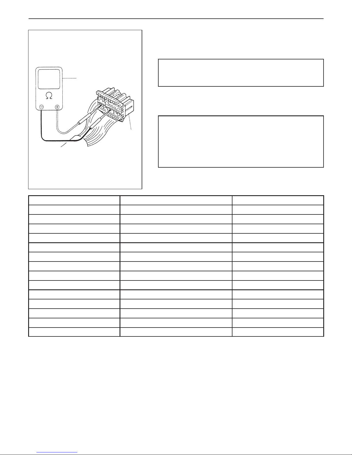
6-38 ENGINE GENERAL INFORMATION AND DIAGNOSIS (TBI FOR G10)
1
2
1. ECM (PCM)
coupler disconnected
2. Ohmmeter
RESISTANCE CHECK
1) Disconnect ECM (PCM) couplers from ECM (PCM) with ignition
switch OFF.
CAUTION:
Never touch terminals of ECM (PCM) itself or connect
voltmeter or ohmmeter.
2) Check resistance between each terminal of couplers disconnected.
CAUTION:
D Be sure to connect ohmmeter probe from wire harness
side of coupler.
D Be sure to turn OFF ignition switch for this check.
D Resistance in table below represents that when parts
temperature is 20_C (68_F).
TERMINALS CIRCUIT STANDARD RESISTANCE
C01-8 to C03-20 H02S-1 heater 11.7 – 14.3 Ω
C02-19 to C03-20 H02S-2 heater 11.7 – 14.3 Ω
C02-12 to C02-2/15 Fuel injector 2.4 – 3.6 Ω
C02-7 to C02-2/15 EVAP canister purge valve 30 – 34 Ω
C02-21 to C03-20 Fuel pump relay 100 – 120 Ω
C02-16 to C02-2/15 ISC actuator relay 100 – 120 Ω
C02-25 to C02-2/15 EFE heater relay 100 – 120 Ω
C02-8 to Body ground Shift solenoid-B 8 – 20 Ω
C02-9 to Body ground Shift solenoid-A 8 – 20 Ω
C02-20 to C02-2/15 Radiator fan control relay 100 – 120 Ω
C02-22 to C02-14 Main relay 100 – 120 Ω
C02-1 to Body ground Ground Continuity
C02-13 to Body ground Ground Continuity
C02-26 to Body ground Ground Continuity
Page 90

ENGINE GENERAL INFORMATION AND DIAGNOSIS (TBI FOR G10) 6-39
INFORMATION SENSORS
-1. MAP sensor
-2. TP sensor
-3. IAT sensor
-4. ECT sensor
-5. Heated oxygen sensor-1
-6. VSS
-7. Ignition coil
-8. Battery
-9. CMP sensor (in Distributor)
-10. A/C contoller (if equipped)
-11. CKP sensor
-12. CTP switch (in ISC actuator)
-13. Heated oxygen sensor-2
OTHERS
A: ECM (PCM)
B: Main relay
C: EVAP canister
D: Injector resistor
E: EFE heater
F: Electric load diode
CONTROL DEVICES
a: Fuel injector
b: EVAP canister purge valve
c: Fuel pump relay
d: Malfunction indicator lamp
e: ISC actuator
f: Radiator fan control relay
g: Igniter
h: EFE heater relay
i: ISC actuator relay
COMPONENT LOCATION
Page 91

6-40 ENGINE GENERAL INFORMATION AND DIAGNOSIS (TBI FOR G10)
“IG COIL METER”
Main relay
Ignition switch
In fuse
Malfunction indicator lamp in combination meter
TABLE A-1 MALFUNCTION INDICATOR LAMP CIRCUIT CHECK – LAMP DOES
NOT COME “ON” AT IGNITION SWITCH ON (BUT ENGINE AT STOP)
CIRCUIT DESCRIPTION
When the ignition switch is turned ON, ECM (PCM) causes the main relay to turn ON (close the contact point).
Then, ECM (PCM) being supplied with the main power, turns ON the malfunction indicator lamp (MIL). When the
engine starts to run and no malfunction is detected in the system, MIL goes OFF but if a malfunction was or is detected, MIL remains ON even when the engine is running.
INSPECTION
STEP ACTION YES NO
1 MIL Power Supply Check
1) Turn ignition switch ON.
Do other indicator/warning lights in
combination meter comes ON?
Go to Step 2. “IG COIL METER” fuse blown,
main fuse blown, ignition
switch malfunction, “B/W”
circuit between “IG COIL
METER” fuse and
combination meter or poor
coupler connection at
combination meter.
2 ECM (PCM) Power and Ground Circuit
Check
Does engine start?
Go to Step 3. Go to TABLE A-3 ECM (PCM)
POWER AND GROUND
CIRCUIT CHECK.
If engine is not cranked, go to
DIAGNOSIS in SECTION 8A.
3 MIL Circuit Check
1) Turn ignition switch OFF and disconnect
connectors from ECM (PCM).
2) Check for proper connection to ECM
(PCM) at terminal C02-17.
3) If OK, then using service wire, ground
terminal C02-17 in connector
disconnected.
Does MIL turn on at ignition switch ON?
Substitute a knowngood ECM (PCM) and
recheck.
Bulb burned out or “V/Y” wire
circuit open.
Page 92

ENGINE GENERAL INFORMATION AND DIAGNOSIS (TBI FOR G10) 6-41
TABLE A-2 MALFUNCTION INDICATOR LAMP CIRCUIT CHECK – LAMP
REMAINS “ON” AFTER ENGINE STARTS
WIRING DIAGRAM/CIRCUIT DESCRIPTION – Refer to table A-1.
INSPECTION
STEP ACTION YES NO
1 Diagnostic Trouble Code (DTC) check
1) Check DTC referring to DTC CHECK section.
Is there any DTC(s)?
Go to Step 2 of ENGINE
DIAG. FLOW TABLE.
Go to Step 2.
2 DTC check
Start engine and recheck DTC while engine
running.
Is there any DTC(s)?
Go to Step 3.
3 MIL Circuit check
1) Turn OFF ignition switch.
2) Disconnect connectors from ECM (PCM).
Does MIL turn ON at ignition switch ON?
“V/Y” wire circuit
shorted to ground.
Substitute a known-good
ECM (PCM) and
recheck.
Page 93

Main fuseIgnition switch
Main fuse
Malfunction indicator lamp in combination meter
Relay box
“IG COIL METER”
6-42 ENGINE GENERAL INFORMATION AND DIAGNOSIS (TBI FOR G10)
TABLE A-3 ECM (PCM) POWER AND GROUND CIRCUIT CHECK – MIL
DOESN’T LIGHT AT IGNITION SWITCH ON AND ENGINE DOESN’T
START THOUGH IT IS CRANKED UP
CIRCUIT DESCRIPTION
When the ignition switch tuned ON, the main relay turns ON (the contact point closes) and the main power is supplied to ECM (PCM).
INSPECTION
STEP ACTION YES NO
1 Main Relay Operating Sound Check
Is operating sound of main relay heard at ignition switch ON?
Go to Step 5. Go to Step 2.
2 Main Relay Check
1) Turn OFF ignition switch and remove main relay (1).
2) Check for proper connection to main relay (1) at terminal
3 and 4.
3) Check resistance between each two terminals. See Fig. 1
and 2.
Between terminals 1 and 2: Infinity
Between terminals 3 and 4: 100 – 120 Ω
4) Check that there is continuity between terminals 1 and 2
when battery is connected to terminals 3 and 4. See Fig. 3.
Is main relay in good condition?
Go to Step 3. Replace main
relay.
3 Fuse Check
Is main “FI” fuse in good condition?
Go to Step 4. Check for short in
circuits connected
to this fuse.
4 ECM (PCM) Power Circuit Check
1) Turn OFF ignition switch, disconnect connectors from ECM
(PCM) and install main relay.
2) Check for proper connection to ECM (PCM) at terminals
C03-20, C02-2, C02-15 and C02-22.
3) If OK, then measure voltage between terminal C03-20 and
ground, C02-22 and ground with ignition switch ON.
Is each voltage 10 – 14 V?
Go to Step 5. “B/W”, “W/R” or
“Bl/B” circuit
open.
Page 94

ENGINE GENERAL INFORMATION AND DIAGNOSIS (TBI FOR G10) 6-43
Fig. 1 for Step 2 Fig. 2 for Step 2 Fig. 3 for Step 2
1. Main relay
2. Relay box
STEP ACTION YES NO
5 ECM (PCM) Power Circuit Check
1) Using service wire, ground terminal C02-22 and
measure voltage between terminal C02-2 and
ground at ignition switch ON.
Is it 10 – 14 V?
Check ground circuits
“Bl/B” and “W/ Bl” for
open.
If OK, then substitute a
known-good ECM
(PCM) and recheck.
Go to Step 6.
6 Is operating sound of main relay heard in Step 1? Go to Step 7. “W/R” or “W / Bl” wire
open.
7 Main Relay Check
1) Check main relay according to procedure in
Step 2.
Is main relay in good condition?
“W/R” or “W / Bl” wire
open.
Replace main relay.
Page 95

MAP sensor
To TP sensor
To other sensors
6-44 ENGINE GENERAL INFORMATION AND DIAGNOSIS (TBI FOR G10)
DTC P0105 MANIFOLD ABSOLUTE PRESSURE (MAP) CIRCUIT
MALFUNCTION
CIRCUIT DESCRIPTION
DTC DETECTING CONDITION POSSIBLE CAUSE
D MAP: 5 kPa, 37.5 mmHg or less
(Low pressure – High vacuums – Low voltage)
or
D MAP: 130 kPa, 975 mmHg or more
(High pressure – Low vacuums – High voltage)
D “G” circuit open
D “Lg” circuit open or shorted to ground
D “Lg / R” circuit open or shorted to ground
D MAP sensor malfunction
D ECM (PCM) malfunction
NOTE:
D When DTC P0105, and / or P0120, P0510 are indicated together, it is possible that “Lg” circuit is open.
D When DTC P0105, P0110, P0115 and /or P0120 are indicated together, it is possible that “G” circuit is
open.
DTC CONFIRMATION PROCEDURE
1) Clear DTC, start engine and keep it at idle for 1 min.
2) Select “DTC” mode on scan tool and check DTC.
Page 96

ENGINE GENERAL INFORMATION AND DIAGNOSIS (TBI FOR G10) 6-45
Fig. 1 for Step 2 Fig. 2 for Step 3
Scan tool
DLC
INSPECTION
STEP ACTION YES NO
1 Was “ENGINE DIAG. FLOW TABLE”
performed?
Go to Step 2. Go to “ENGINE DIAG.
FLOW TABLE”.
2 Check MAP Sensor and Its Circuit.
1) Connect scan tool to DLC with ignition
switch OFF.
2) Turn ignition switch ON.
3) Check intake manifold pressure.
See Fig. 1.
Is it 130 kPa or more or 5 kPa or less?
Go to Step 3. Intermittent trouble.
Check for intermittent
referring to
“INTERMITTENT AND
POOR CONNECTION” in
Section 0A.
3 Check Wire Harness.
1) Disconnect MAP sensor connector with
ignition switch OFF.
2) Check for proper connection of MAP
sensor at “Lg/R” and “G” wire
terminals.
3) If OK, then with ignition switch ON, check
voltage at each of “Lg” and “Lg/R” wire
terminals. See Fig. 2.
Is voltage about 4 – 6 V at each terminal?
Go to Step 4. “Lg” wire open or
shorted to ground circuit or
shorted to power circuit,
“Lg/R” wire open or
shorted to ground, poor
C01-5 connection or
C01-1 connection.
If wire and connection are
OK, confirm that MAP
sensor is normal and then
substitute a known-good
ECM (PCM) and recheck.
NOTE: When battery
voltage is applied to
“Lg” wire, it is possible
that MAP sensor is also
faulty.
4 Check MAP sensor according to “MAP
Sensor Individual Check” in Section 6E1.
Is it in good condition?
“Lg” wire shorted to
“Lg/R” wire, “G” wire
open, poor C01-9
connection.
If wire and connection are
OK, substitute a knowngood ECM (PCM) and
recheck.
Replace MAP sensor.
Page 97

To other sensors
IAT sensor
6-46 ENGINE GENERAL INFORMATION AND DIAGNOSIS (TBI FOR G10)
DTC P0110 INTAKE AIR TEMP. (IAT) CIRCUIT MALFUNCTION
CIRCUIT DESCRIPTION
DTC DETECTING CONDITION POSSIBLE CAUSE
D Low intake air temperature (High voltage-High resistance)
or
D High intake air temperature (Low voltage-Low resistance)
D “Gr” circuit open or shorted to power
D “G” circuit open
D IAT sensor malfunction
D ECM (PCM) malfunction
NOTE:
D When DTC P0105, P0110, P0115 and P0120 are indicated together, it is possible that “G” circuit is open.
D Before inspecting, be sure to check that ambient temperature is higher than – 40_C (– 40_F).
DTC CONFIRMATION PROCEDURE
1) Clear DTC, start engine and keep it at idle for 1 min.
2) Select “DTC” mode no scan tool and check DTC.
Page 98

ENGINE GENERAL INFORMATION AND DIAGNOSIS (TBI FOR G10) 6-47
Fig. 1 for Step 2 Fig. 2 for Step 3 Fig. 3 for Step 4
Scan tool
DLC
INSPECTION
STEP ACTION YES NO
1 Was “ENGINE DIAG. FLOW TABLE” performed? Go to Step 2. Go to “ENGINE DIAG.
FLOW TABLE”.
2 Check IAT Sensor and Its Circuit.
1) Connect scan tool to DLC with ignition switch
OFF.
2) Turn ignition switch ON.
3) Check intake air temp. displayed on scan tool.
See Fig. 1.
Is –40_C (–40_F) or 119_C (246_F) indicated?
Go to Step 3. Intermittent trouble.
Check for intermittent
referring to “Intermittent
and Poor Connection”
in Section 0A.
3 Check Wire Harness.
1) Disconnect IAT sensor connector with ignition
switch OFF.
2) Check for proper connection to IAT sensor at
“Gr” and “G” wire terminals.
3) If OK, then with ignition switch ON, is voltage
applied to “Gr” wire terminal about 4 – 6 V? See
Fig. 2.
Go to Step 5. “Gr” wire open or
shorted to power, or
poor C01-14
connection.
If wire and connection
are OK, substitute a
known-good ECM
(PCM) and recheck.
4 Does scan tool indicate –40_C (–40_F) at Step 2. Go to Step 6. Go to Step 5.
5 Check Wire Harness.
1) Check intake air temp. displayed on scan tool
with ignition switch ON.
Is –40_C (–40_F) indicated?
Replace IAT sensor. “Gr” wire shorted to
ground.
If wire is OK, substitute
a known-good ECM
(PCM) and recheck.
6 Check Wire Harness.
1) Using service wire, connect IAT sensor
connector terminals.
2) Check intake air temp. displayed on scan tool
with ignition switch ON. See Fig. 3.
Is 119_C (246_F) indicated?
Replace IAT sensor. “Gr” wire open or poor
C01-9 connection.
If wire and connection
are OK, substitute a
known-good ECM
(PCM) and recheck.
Page 99

ECT sensor
To combination
(ECT) meter
To other sensors
6-48 ENGINE GENERAL INFORMATION AND DIAGNOSIS (TBI FOR G10)
DTC P0115 ENGINE COOLANT TEMPERATURE (ECT) CIRCUIT
MALFUNCTION
CIRCUIT DESCRIPTION
DTC DETECTING CONDITION POSSIBLE CAUSE
D Low engine coolant temperature (High voltage-High resistance)
or
D High engine coolant temperature (Low voltage-Low resistance)
D “Gr / W” circuit open or shorted to power
D “G” circuit open
D ECT sensor malfunction
D ECM (PCM) malfunction
NOTE:
Before inspecting, be sure to check that coolant temp. meter in combination meter indicates normal operating temperature (Engine is not overheating).
DTC CONFIRMATION PROCEDURE
1) Clear DTC, start engine and keep it at idle for 1 min.
2) Select “DTC” mode on scan tool and check DTC.
Page 100

ENGINE GENERAL INFORMATION AND DIAGNOSIS (TBI FOR G10) 6-49
Fig. 1 for Step 2 Fig. 2 for Step 3 Fig. 3 for Step 4
Scan tool
DLC
INSPECTION
STEP ACTION YES NO
1 Was “ENGINE DIAG. FLOW TABLE” performed? Go to Step 2. Go to “ENGINE DIAG.
FLOW TABLE”.
2 Check ECT Sensor and Its Circuit.
1) Connect scan tool with ignition switch OFF.
2) Turn ignition switch ON.
3) Check engine coolant temp. displayed on scan
tool. See Fig. 1.
Is –40_C (–40_F) or 119_C (246_F) indicated?
Go to Step 3. Intermittent trouble.
Check for intermittent
referring to “Intermittent
and Poor Connection”
in Section 0 A.
3 Check Wire Harness.
1) Disconnect ECT sensor connector.
2) Check engine coolant temp. displayed on scan
tool.
Is –40_C (–40_F) indicated?
Replace ECT sensor. “Gr /W” wire shorted to
ground.
If wire is OK, substitute
a known-good ECM
(PCM) and recheck.
4 Does scan tool indicate –40_C (–40_F) at Step 2. Go to Step 6. Go to Step 5.
5 Check Wire Harness.
1) Disconnect ECT sensor connector with
ignition switch OFF.
2) Check for proper connection to ECT sensor at
“G” and “Gr/W” wire terminals.
3) If OK, then with ignition switch ON, is voltage
applied to “G” wire terminal about 4 – 6 V?
See Fig. 2.
Go to Step 4. “Gr / W” wire open or
shorted to power, or
poor C01-7 connection.
If wire and connection
are OK, substitute a
known-good ECM
(PCM) and recheck.
6 Check Wire Harness.
1) Using service wire, connect ECT sensor
connector terminals. See Fig. 3.
2) Turn ignition switch ON and check engine
coolant temp. displayed on scan tool.
Is 119_C (246_F) indicated?
Replace ECT sensor. “G” wire open or
poor C01-9 connection.
If wire and connection
are OK, substitute a
known-good ECM
(PCM) and recheck.
 Loading...