

Page 1

SECTION 14
www.zukioffroad.com
TRANSFER GEAR BOX
CONTENTS
14-l.
14-2.
14-3.
14-4.
14-5.
14-6.
14-7.
14-8.
14-9.
14-10.
GENERAL DESCRIPTION
SELECTIVE FLOWS OF TRANSFER DRIVE
GEAR RATIO DATA . . . . . . . . . . . . . . . . . . . . . . . . . . . . . . . . . . . . . 14-4
TRANSFER SERVICES NOT REQUIRING
TRANSFER REMOVAL . . . . . . . . . . . . . . . , . . . . . . . . . . . . . . . . . . . 14-5
REMOVAL .............................................
DISASSEMBLY
INSPECTION OF COMPONENTS
REASSEMBLY
MAINTENANCE SERVICES . . . . . . . . . . . . . . . . . . . . . . . . . . . . . . . 14-22 12
TIGHTENING TORQUE . . . . . . . . . . . . . . . . . . . . . . . . . . . . . . . . . . 14-23
..........................................
.........................................
................................. 14-2
..................
...........................
14-3
14-6
14-8
14-12
14-14
14-1
Page 2
14-1. GENERAL DESCRIPTION
The transfer gear box is an auxiliary transmission for on-off control of two-speed drive transmitted to
both front and rear axles concurrently and provides additional speed reductions, HIGH and LOW, for any
selection of main transmission gears.
The functions of this auxiliary transmission are mainly two-selection between four-wheel drive (front and
rear axles) and two-wheel drive (rear axle) and between HIGH and LOW for four-wheel drive. Three
propeller shafts are associated with the gear box.
These functions are accomplished by means of four shafts arranged in three-axis configuration and two
sliding clutches. The selection is effected by actuating these clutches from a single control lever located
beside the driver’s seat. The gear box is mounted on a chassis frame.
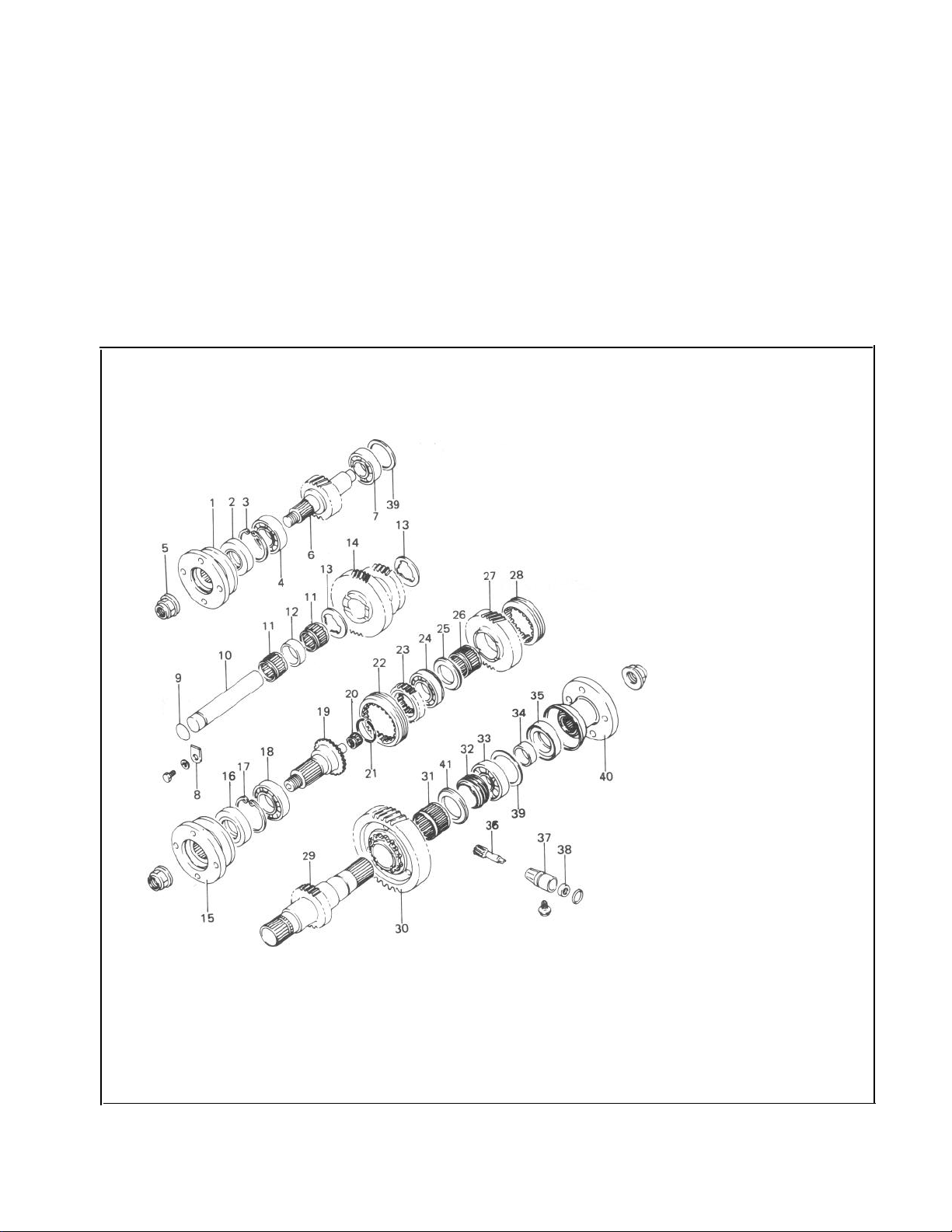
1.
Flange
Oil seal
2.
3. Circlip
Bearing
4.
5. Nut
Input shaft
6.
7. Bearing
Counter shaft lock plate
8.
9. O-ring
Counter shaft
10.
Bearing
11.
12.
Spacer
Thrust washer
13.
14. Counter gear
Flange
15.
16.
Oil seal
17. Circlip
18.
Bearing
Output front shaft
19.
Bearing
20.
21. Circlip
Sleeve
22.
Hub
23.
24.
Bearing
Thrust washer
25.
Bearing
26.
Output high gear
27.
Sleeve
28.
Output rear shaft
29.
Output low gear
30.
31.
Bearing
Speedometer drive gear
32.
Bearing
33.
Retainer
34.
Oil seal
35.
Speedometer driven gear
36.
Speedometer gear case
37.
Oil seal
38.
Shim
39.
Flange
40.
Washer
41.
Fig.
14- 1
Fig. 14-1
14-2
Page 3
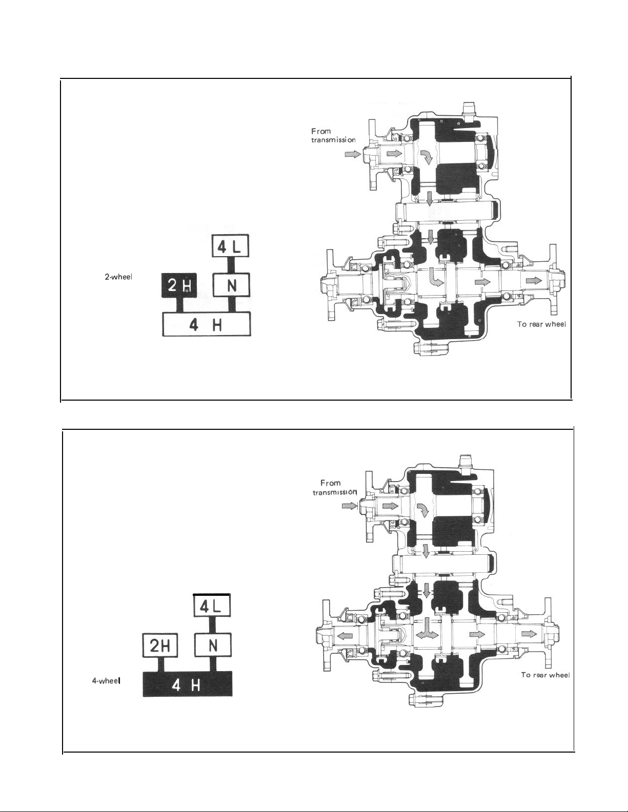
14-2. SELECTIVE FLOWS OF TRANSFER DRIVE
2-Wheel Drive (Rear-Wheel Drive)
Rear shifter fork pushes rear clutch sleeve into
“high” gear, thus coupling the gear to output
rear shaft.
Drive flows from input shaft to output rear shaft
through big gear, “high” gear and rear clutch.
Gear shift control lever position
a-wheel drive
(Rear wheel drive)
tra”SmiSSion
Fig. 14-2
4-Wheel Drive HIGH (All-Wheel Drive on HIGH)
Under the conditions of rear-wheel drive,
described above, front shifter fork pushes the
sleeve of front clutch onto the toothed clutch
ring, thus coupling output rear shaft to output
front shaft. Front shaft and rear
together on HIGH.
Gear shift control lever position
4-wheel
drive HIGH
shaft run
To front wheel
From
.
transm’ss’on
e
Fig. 14-3
14-3
Page 4
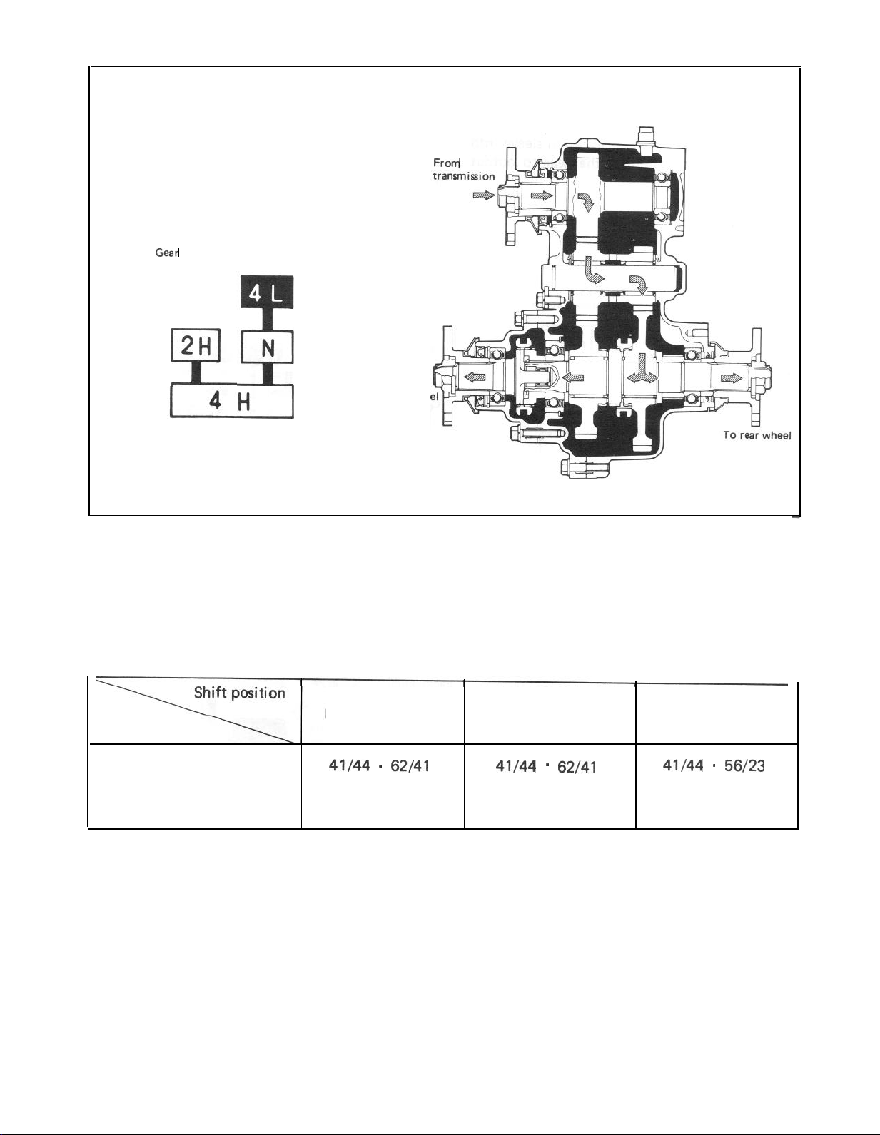
4-Wheel Drive LOW (All-Wheel Drive on LOW)
Front shifterforkactuates front clutch to couple
rear shaft to front shaft; and rear shifter fork
actuates rear clutch to couple “low” gear to rear
shaft. Front shaft and rear shaft run together on
LOW.
Gear shift control lever position
4-wheel
drive LOW
2H
From
5l
Fig. 14-4
14-3. GEAR RATIO DATA
Gear
To front whe
Rear-wheel drive
41/44 -
62/41
All-wheel drive high
41/44
-
62/41
All-wheel drive low
41/44 - 56/23
14-4
Reduction
1.409
1.409
2.268
Page 5

14-4. TRANSFER SERVICES NOT REQUIRING TRANSFER REMOVAL
Following parts or components do not require transfer removal to receive services (replacement, inspec-
tion) :
Part or Component
1. Universal-joint yoke flanges
2. Front drive shift shaft fork
3. Transfer output front shaft oil seal
4. Transfer output front shaft bearing
5. Transfer output front shaft
6. Transfer front case
7. Front drive clutch hub
8. Front drive clutch sleeve
9. Transfer input shaft oil seal
10. 4WD indicator light switch
11. Speedometer driven gear
12. Gear shift control lever
13. Gear shift control boot No. 1, No. 2
14. Gear shift control lever spring seat
.
Nature of Service
Replacement or inspection
Replacement or inspection
I
Replacement or inspection
Replacement
Replacement
Replacement
Replacement or inspection
Replacement or inspection
Replacement
Replacement or inspection
Replacement or inspection
Replacement or inspection
Replacement
Replacement or inspection
14-5
Page 6
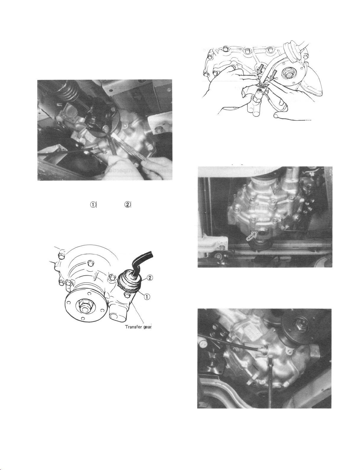
14-5. REMOVAL
1) Lift up car and remove securing bolts from
each universal-joint flange connection to
sever 3 propeller shafts from transfer gear
box.
Fig. 14-5
2) Remove clamp @ and boot @ from transfer
gear box.
Fig. 14-7
4) Drain out oil from gear box by loosening
its drain
plug.
Transfer‘gear case
Fig. 14-6
3) Twist control lever guide counterclockwise
while pushing it down; this will permit lever
to be removed from gear box.
14-6
Fig. 14-8
Fig.
14-8
5) Disconnect speedometer drive cable from
transfer gear box.
Fig. 14-9
Page 7
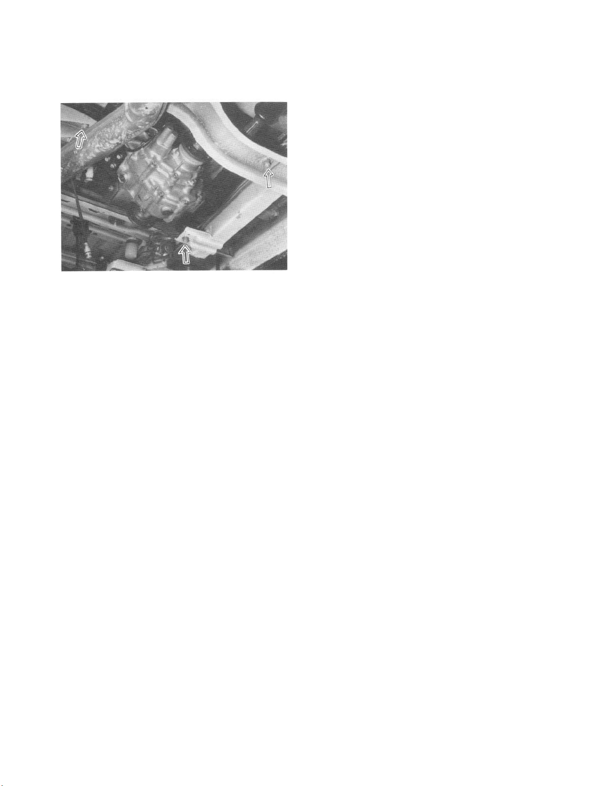
6) Disconnect 4WD switch lead wire at coupler.
7) Remove 3 mounting nuts securing gear box
to
chassis, and take down gear box.
Fig. 14-11
14-7
Page 8

14-6. DISASSEMBLY
Universal-Joint Yoke Flanges
There are 3 flanges to be removed: one from
input shaft and other from output front and rear
shafts. Lock flange so that it will not turn, and
loosen and remove nut holding flange to the
shaft. Draw off flange.
Fig. 14-12 @ Special tool (09930401131
Fig. 14-16
Remove bolts securing transfer front case,
and
take off case.
Speedometer Driven Gear
Loosen speedometer driven gear case bolt
and remove speedometer driven gear case with
gear.
Fig. 14-15
Transfer Front Case
Remove the indicator light switch from front
case.
NOTE:
Use care not to lose switch ball. This ball is
larger than interlock ball and locating balls.
Fig. 14-17
By tapping output front shaft with a plastic
hammer,
front case.
Fig. 14-18
remove output front shaft from
14-8
Page 9

After removing oil seal, remove circlip and drive
bearing out of front case by using bearing
installer (special tool).
Bearing installer 0 : (09913-76010)
Fig. 14-19
Transfer Center Case
Remove bolts fastening center case and rear
case together.
Do not
loosen bolt @ at
this
point.
Fig. 14-21
Fig. 14-20
By tapping rear case and output rear shaft with.
a plastic hammer, separate center and rear case.
Fig. 14-22
Given below are procedures for disassembling
component parts of center case as separted from
rear case.
1) Loosen gear shift locating spring plug and
take out spring and locating ball.
Fig. 14-23
14-9
Page 10

2) Using spring pin remover (special tool), drive
2 spring pins out of front drive shift shaft
@
and reduction shift shaft
Spring pin remover
@
0.
:
(09922-85811).
Fig. 14-26
Fig. 14-24
3) Remove forks and shift shafts.
NOTE:
At this time, locating ball and spring will jump
out of hole, use care not to lose them.
5) Pull out counter gear,
Remove counter shaft
loosening counter shaft
bearings and spacer.
from center case by
lock plate bolt.
Fig. 14-27
6) Remove input shaft from center case by
hammering thick part of case or input
shaft center with a plastic hammer.
Fig. 14-25
4) Hammer output rear shaft with a plastic
hammer to drive it out of center
case.
14-10
Fig. 14-28
Page 11

7) Remove output shaft rear bearing and
retainer together by using bearing puller.
After removing bearing, speedometer drive
gear, thrust washer, output low gear and
needle roller bearing can be removed.
Fig. 14-29
8) Remove front drive clutch hub circlip and
pull clutch hub off shaft by using bearing
puller and puller attachment (special tool A).
(A)
09926-5801 0
Fig. 14-31
10) When input shaft is removed or center case
and rear case are separated, input shaft
bearings may come off. In such a case,
bearings can be removed from shaft by using
bearing puller.
NOTE:
Use care to prevent damage to needle roller
bearing in output rear shaft when removing
clutch hub.
/
(A)
099263801 0
Fig. 14-30
9) Remove front bearing by using bearing
puller and puller attachment (special tool
A).
NOTE:
Use care to prevent damage to needle roller
bearing in output rear shaft while bearing is
being removed.
**
i
ta
“+
Fig. 14-32
14-11
Page 12

11) When input shaft is removed, front bearing
may be left in case. In this case, after removing oil seal and circlip, bearing can be taken
out of case by using bearing installer (special
tool).
Bearing installer @ : (09913-75810)
Fig. 14-33
Transfer Rear Case
1) When center case and rear case are separated,
input shaft may be left in rear case. In this
case, remove input shaft from rear case by
hammering thick part of case with a plastic
hammer.
14-7. INSPECTION OF COMPONENTS
Gear Teeth
Inspect gear teeth 0, internal teeth of rear
clutch sleeve @ and clutch teeth of gear 3. for
wear, cracking, chipping and other
malcondition. Replace gear or sleeve as necessary.
Fig. 14-35
Fig. 14-34
14-12
Fig. 14-36
Locating Spring
Check each shifter fork shaft locating spring for
strength by measuring its free length. If length is
noted to be less than service limit, replace it.
Free length of
locating spring
Page 13

Fig. 14-37
Bearings
Check each bearing by spinning its outer race by
hand to “feel” smoothness of rotation. Replace
bearing if noted to exhibit sticking, resistance
or abnormal noise when spun or rotated by
hand.
Fig. 14-38
Fig. 14-39 Output high gear
Fig. 14-40 Output low gear
Gear Shift Shafts
Check each part as indicated in below figures for
uneven wear. Replace defective parts.
Side Clearance of Gears
With gear, bearing and thrust washer installed
on shaft, check for side clearances of gears.
If clearance exceeds service limit, replace thrust
washer.
Side clearance
I
of gear
output
gears
low gear
high gear
Standard
0.175 (0.007 -
0.325mm
0.012in)
Service limit
0.7mm
(0.027in)
I
Fig. 14-41
14-13
Page 14

4WD Gear Shift Lever
Check lower end of gear shift lever where gear
shift fork shaft contacts @ for wear and any
kind of damage. Worn or damaged shift lever
must be replaced with new one.
Fig. 14-42
14-8. REASSEMBLY
NOTE:
l All parts to be used in reassembly must be
perfectly clean.
l Oil or grease sliding and rubbing surfaces of
transfer components just before using them
in reassembly with gear oil and SUZUKI
SUPER GREASE A (99000-25010).
l
Oil seals, “0” rings, gaskets and similar sealing
members must be in perfect condition. For
these members, use replacement parts in
stock.
l Tightening torque is specified for important
-
fasteners
other components. Use torque wrenches and
constantly refer to specified data given in
P. 14-23.
Input Shaft
Press-fit bearings onto both sides of input shaft
by using bearing installer (special tool).
Bearing installer (A) :
mainly bolts - of transfer and
(09913-84510)
Fig. 14-43
(A)
14-14
Page 15

Output Rear Shaft
Install following parts onto shaft in such order
and directions as prescribed in the figure.
6 9
1. Circlip
2. Hub
3.
Bearing
4.
Bearing
outer ring
5. Thrust washer
6. Output
7. Bearing (long)
8. Output rear shaft
high gear
9.
Sleeve
10. Bearing (short)
11. Outputlowgaar
12.
Thrust washer
13. Speed meter drive gear
14. Bearing
15. Retainer
2) Fit circlip @ securely into groove in shaft.
Fig. 14-46
3) After installing sleeve, bearing (short), low
gear and thrust washer, press-fit speedometer
drive gear by using bearing installer (special
tool).
Bearing installer (A) : (09913-84510)
(A)
Fig. 14-44
1) After installing bearing (long), high gear and
thrust washer, press-fit bearing 1. and then
hub @ by using bearing installer (special
tool).
Bearing installer (A) : (0991384510)
Fig. 14-45
Fig. 14-47
4) Press-fit bearing @ and the retainer @ by
using bearing installer (special tool).
Bearing installer (A) : (0991384510)
Fig. 14-48
14-15
Page 16

Shim Adjustment of Input and Output Shafts
Clearance in thrust direction of both input and
output shafts is adjusted by putting shims
between input shaft rear bearing and rear case
for input shaft and between output shaft rear
bearing and rear case for output shaft.
As thrust clearance is specified as follows
determine shim thickness to meet specification
according to the following procedures.
Thrust clearance
specification
0.05 - 0.15 mm
(0.002 - 0.006 in.)
[Input shaft]
1) Take measurement “A” of rear case as shown
in figure below by using depth gauge,
2) Take measurement
“6”
of center case with
bearing circlip installed.
3) Take measurement
“C” (between bearing
inner races) of input shaft with bearings
installed, by using micrometer.
NOTE:
l
Before measuring, make sure that each
bearing
is free from abnormal noise or resistance by
spinning its outer race.
l Each measurement in above steps 1) to 3)
must be taken accurately in careful manner,
If shim thickness is determined based on
rough measurement, clearance of each shaft in
thrust direction will not satisfy specification.
And improper clearance may cause oil leakage,
broken bearing and abnormal noise.
l Take the same measurement at 3 to 4 diffe-
rent positions and use their mean.
1.1.
14-48-14-48-
Fig.Fig.
Fig. 14-48-1
Center caseCenter case
2.2.
Rear caseRear case
3.3.
Input shaftInput shaft
4. Output shaft4. Output shaft
11
Bearing circlipBearing circlip
5.5.
GasketGasket
6.6.
Gasket thicknessGasket thickness
7.7.
(0.3
mm or 0.012 in)
(0.3
mm or 0.012 in)
4) Using measurements obtained in steps 1) to 3)
and equation described below, calculate shim
thickness which is necessary for proper
thrust clearance.
Thrust clearance = (“A” + “B” + Gasket
thickness) - “C”
As the above equation holds for thrust
clearance and gasket thickness is specified as
0.3 mm and thrust clearance as 0.05 to 0.15
mm, shim thickness is calculated by the
following equation.
Shim thickness = (“A” + “B” + 0.3 )
-
(“C” + 0.05 - 0.15)
14-16
[Example]
Supposing A, B and C are as follows;
A = 81.35 mm (3.203 in.)
B = 35.70 mm (1.405 in.)
C = 117.05 mm (4.608 in.)
Shim thickness = (81.35 + 35.70 + 0.3)
6
(117.05 + 0.05 N 0.15)
=
117.35- 117.10~
-
117.20
= 0.25 - 0.15
In this case, use of 0.15 to 0.25 mm (0.006 to
0.009 in) thick shim(s) will ensure specified
thrust clearance which is 0.05 to 0.15 mm
(0.002 to 0.006 in). Therefore 2 pieces of
0.1 mm (0.004 in) thick shim should be
selected in available shims below to satisfy
thickness.
Page 17

5) When shim thickness is determined, select
proper shim(s) from among the following
shims and use it (them) between input shaft
rear bearing and rear case when matching
center case and rear case.
Available shim 0.1,
size (thickness)
(0.004,0.012,0.020
0.3,0.5
mm
in.)
[Output shaft]
Just as with input shaft, take measurements of
“A’ “, “B’ ” and “C’ ” as indicated in Fig.
14-48-1, calculate shim thickness and install
proper shim(s) between output shaft rear bearing
and rear case when matching center case and
rear case.
I
Fig. 14-48-2
fig.
14-48-2
1. Shim for input shaft
2. Shim for output shaft
14-17
Page 18

Rear Case
1) Install oil seal in rear case and apply grease
to oil seal lip.
Fig. 14-49
2) Install counter shaft thrust washer to rear
case, bringing its face without depressions
against case and fit its bent portion securely
into groove in case.
Center Case
1) Install input shaft front bearing circlip and
oil seal in center case.
Snap ring pliers @ : (09900~6108)
Fig. 14-51
2) Install input shaft to center case.
NOTE:
Apply ample amount of grease to both surfaces
of washer so as to lubricate sliding surfaces and
prevent washer from moving out of place or
slipping off.
Fig.
14-50
Fig. 14-50
Fig. 14-52
Fig.
14-52
3) After greasing 0 ring on counter shaft,
insert shaft into center case and secure
shaft with lock plate and bolt.
14-18
Fig. 14-53
Fig.
14-53
Page 19

4) Install the counter shaft thrust washer to
center case. For installation, apply ample
amount of grease to both faces of the washer
so as to lubricate sliding surfaces and prevent
it from moving out of place or slipping off
and bring its face without depressions against
center case, and fit its bent portion into
groove in case securely.
Fig. 14-54
Fig.
14-54
Fig. 14-56
Fig. 14-56
7) When installing front drive shift shaft and
reduction shift shaft in center case, install
spring 0, ball 0, shaft 0, ball @, shaft
0,
ball 8, spring 0 and plug 8. in that
order.
5) Install needle roller bearings, spacer and
counter gear on counter shaft.
Fig. 14-55
Fig. 14-55
6) Install output shaft assembly to center case.
d 18-3ON.m
Fig. 14-57
Fig. 14-57
8) Fit forks on shift shafts and lock them
with spring pins. Forks should be fitted in
correct direction
according to below figure.
(1.8 - 3.0 kg-m
(13.5 - 21.5
lb-ft)
1
Fig. 14-58
Fig. 14-58
14-19
14-19
Page 20

Center and Rear Cases
1) Check center case (or rear case) to ensure
that it is provided with 2 dowel pins
0.
Fig. 14-59
2) Put gasket on center case. Bring rear case
and center case into match and apply
uniform force gradually all around rear case
with a plastic hammer. Tighten center case
securing bolts to specified torque.
Fig. 14-61
NOTE:
l
Matching must be made carefully so as not to
move countershaft thrust washers out of place.
l
Be sure to install shims determined in previ-
ous item
Output Shafts”
“Shim Adjustment of Input and
between input shaft rear
bearing and rear case and between output
shaft rear bearing and rear case.
Fig. 14-60
Fig. 14-62
3) Apply grease to output front shaft rear
bearing.
Fig. 14-63
14-20
Page 21

Front Case
1) Install bearing, circlip and oil seal to front
case. Apply grease to oil seal lip and install
output front shaft using bearing installer
(special tool).
Bearing installer (A) : (09913-76010)
Fig. 14-64
2) Put gasket on center case.
3) Check front case to ensure that it is provided
with 2 dowel pins.
Fig. 14-66
5) When installing speedometer driven gear
and its gear case in rear case, apply grease to
0 ring and oil seal lip, and align bolt holes
in rear case and driven gear case.
Fig. 14-65
4) Install front case to center case.
Fig. 14-67
6) Install 4WD ball and switch. Then clamp
switch lead wire properly.
/
Fig. 14-68
1.6 - 2.3 kgm
(12.0 - 16.5
lb-h)
14-21
Page 22

7) Install propeller shaft flanges and tighten
nuts to specified torque and
talk
the nuts.
8) Upon completion of entire assembly work,
install transfer in chassis body in reverse
sequence of removal. Pour gear oil into
transfer gear box.
Refer to information given in next oil and
oil capacity for oil to be used and specified
amount.
NOTE:
When installing oil filler and drain plugs to
transfer case, apply sealant (SUZUKI BOND
No.1215, 99000-31110) to thread part of plug.
14-9. MAINTENANCE SERVICES
Oil Level
Oil level must be checked with car held in
horizontal position in both front to rear and side
to side directions.
Oil level plug and oil filler plug are one and the
same as shown in figure.
If oil flows out of filler plug hole or if oil level is
found up to hole when plug is removed, amount
of oil is appropriate. Replenish oil if noted as
insufficient.
Oil and Oil Capacity
Whenever car is lifted up for any service including oil change,
transfer gear box for oil leakage. Correct defects,
if any, and change or refill oil.
make sure to check around
Transfer oil capacity
Transfer oil Gear oil SAE
specification
0.8 litre
75W-80
(1.7/l .4
8OW-90,
or
75W-90
US/Imp. pt)
It is highly recommended to use SAE
gear oil.
For viscosity chart, refer to P. 1-20.
@ : Oil drain plug
Fig. 14-70
@ : Oil filler & level plug
75W-90
14-22
Page 23

14-10. TIGHTENING TORQUE
Fastening parts
Front case bolt
Center case bolt
Counter shaft lock
Counter shaft lock
plate bolt
Universal
Universal joint
joint flange
flange nut
Transfer mounting
bracket bolt
Transfer mounting nut
Cross joint bolt & nut
Oil filler and drain
plug
14-23
 Loading...