

Page 1
Page 2
FOREWORD
This manual contains an introductory description on
the SUZUKI GZ250 and procedures for its inspection/service and overhaul of its main components.
Other information considered as generally known is
not included.
Read the GENERAL INFORMATION section to familiarize yourself with the motorcycle and its maintenance. Use this section as well as other sections as a
guide for proper inspection and service. This
manual will help you know the motorcycle better so
that you can assure your customers of fast and reliable service.
This manual has been prepared on the basis
of the latest specifications at the time of publication. If modifications have been made
since then, differences may exist between
the content of this manual and the actual motorcycle.
Illustrations in this manual are used to show
the basic principles of operation and work
procedures. They may not represent the actual motorcycle exactly in detail. This
manual is written for persons who have
enough knowledge, skills and tools, including special tools, for servicing SUZUKI motorcycles. If you do not have the proper
knowledge and tools, ask your authorized
SUZUKI motorcycle dealer to help you.
GROUP INDEX
GENERAL INFORMATION
PERIODIC MAINTENANCE
ENGINE
FUEL AND LUBRICATION
SYSTEM
CHASSIS
ELECTRICAL SYSTEM
SERVICING INFORMATION
WARNING
Inexperienced mechanics or mechanics
without the proper tools and equipment
may not be able to properly perform the
service described in this manual. Improper repair may result in injury to the mechanic and may render the motorcycle unsafe for the rider and passenger.
SUZUKI MOTOR CORPORATION
Motorcycle Service Department
© COPYRIGHT SUZUKI MOTOR CORPORATION 1998
Page 3
HOW TO USE THIS MANUAL
TO LOCATE WHAT YOU ARE
LOOKING FOR:
1. The text of this manual is divided into sections.
2. The section titles are listed in the GROUP INDEX.
3. Holding the manual as shown at the right will allow
you to find the first page of the section easily.
4. The contents are listed on the first page of each section to help you find the item and page you need.
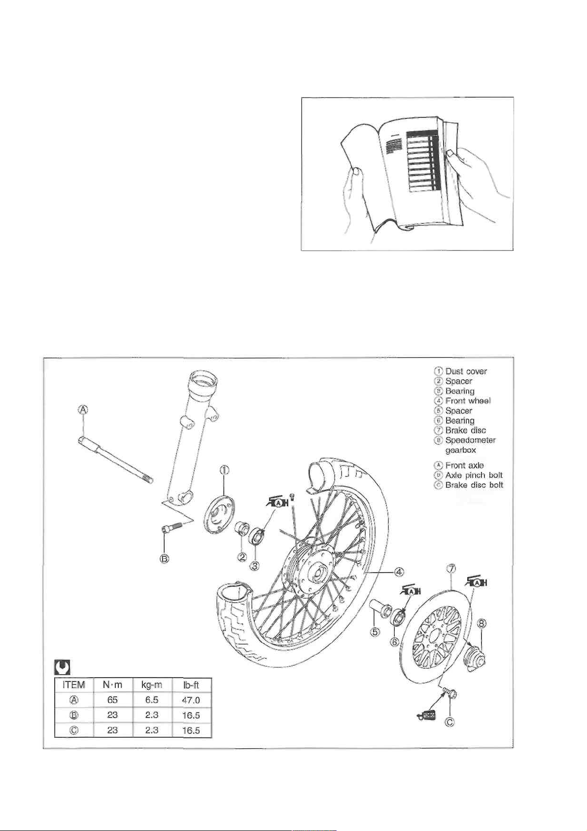
COMPONENT PARTS AND WORK TO BE DONE
Under the name of each system or unit, is its exploded view. Work instructions and other service
information such as the tightening torque, lubricating points and locking agent points, are provided.
Example: Front wheel
Page 4
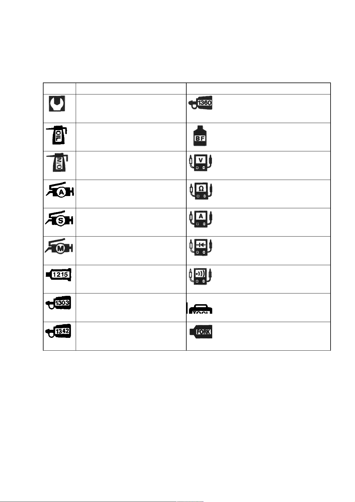
SYMBOL
Listed in the table below are the symbols indicating instructions and other information necessary for
servicing. The meaning of each symbol is also included in the table.
SYMBOL
DEFINITION
SYMBO
L DEFINITION
Torque control required.
Data beside it indicates specified
torque.
Apply THREAD LOCK "1360".
Apply oil. Use engine oil unless
otherwise specified.
Apply or use brake fluid.
Apply molybdenum oil solution (mixture of engine oil and SUZUKI MOLY
PASTE in a ratio of 1 : 1).
Measure in voltage range.
Apply SUZUKI SUPER GREASE
"A".
99000-25010
Measure in resistance range.
Apply SUZUKI SILICONE GREASE.
Measure in current range.
Apply SUZUKI MOLY PASTE.
Measure in diode test range.
Apply SUZUKI BOND "1215".
Measure in continuity test range.
Apply THREAD LOCK SUPER
"1303".
99000-32030
Use special tool.
Apply THREAD LOCK "1342".
Use fork oil. 99000-
Page 5

GENERAL INFORMATION
----------------------------------------- CONTENTS ---------------------------------------------- 1
WARNING/CAUTION/NOTE ............................................................... 1- 1
GENERAL PRECAUTIONS ................................................................ 1- 1
SUZUKI GZ250X ('99-MODEL) ........................................................... 1-3
SERIAL NUMBER LOCATION ........................................................... 1-3
FUEL AND OIL RECOMMENDATIONS .............................................. 1-3
FUEL ............................................................................................... 1-3
ENGINE OIL ................................................................................. 1-4
BRAKE FLUID .............................................................................. 1-4
FRONT FORK OIL .......................................................................... 1-4
BREAK-IN PROCEDURES ................................................................. 1-4
INFORMATION LABELS .................................................................... 1-5
SPECIFICATIONS ............................................................................. 1-6
COUNTRY AND AREA CODES ........................................................ 1-8
Page 6

1-1 GENERAL INFORMATION
WARNING/CAUTION/NOTE
Please read this manual and follow its instructions carefully. To emphasize special information, the
symbol and the words WARNING, CAUTION and NOTE have special meanings. Pay special attention
to the messages highlighted by these signal words.
WARNING
Indicates a potential hazard that could result in death or injury.
CAUTION
Indicates a potential hazard that could result in motorcycle damage.
NOTE:
Indicates special information to make maintenance easier or instructions clearer.
Please note, however, that the warnings and cautions contained in this manual cannot possibly cover
all potential hazards relating to the servicing, or lack of servicing, of the motorcycle. In addition to the
WARNINGS and CAUTIONS stated, you must use good judgement and basic mechanical safety principles. If you are unsure about how to perform a particular service operation, ask a more experienced
mechanic for advice.
GENERAL PRECAUTIONS
WARNING
Proper service and repair procedures are important for the safety of the service mechanic and the safety and reliability of the motorcycle.
When 2 or more persons work together, pay attention to the safety of each other.
When it is necessary to run the engine indoors, make sure that exhaust gas is forced
outdoors.
When working with toxic or flammable materials, make sure that the area you work in is
well ventilated and that you follow all of the manufacturer's instructions. Never use
gasoline as a cleaning solvent.
To avoid getting burned, do not touch the engine, engine oil and exhaust system until
they have cooled.
After servicing fuel, oil, exhaust or brake systems, check all of the lines and fittings
related to the system for leaks.
Page 7

GENERAL INFORMATION 1-2
CAUTION
* If parts replacement is necessary, replace the parts with Suzuki Genuine Parts or their
equivalent.
* When removing parts that are to be reused, keep them arranged in an orderly manner
so that they may be reinstalled in the proper order.
* Be sure to use special tools when instructed.
* Make sure that all parts used in reassembly are clean. Lubricate them when specified.
* Use the specified lubricant, bond, or sealant.
* When removing the battery, disconnect the negative cable first and then the positive
cable.
* When reconnecting the battery, connect the positive cable first and then the negative
cable, and cover the positive terminal with the terminal cover.
* When performing service to electrical parts, disconnect the battery negative cable unless
the service procedure requires the battery power.
* When tightening cylinder head and crankcase bolts and nuts, tighten the larger sizes
first. Always tighten the bolts and nuts from the inside working out, in a crisscross
pattern and to the specified tightening torque.
* Whenever you remove oil seals, gaskets, packing, O-rings, self-locking nuts, locking
washers, cotter pins, circlips, and certain other parts as specified, be sure to replace them
with new ones. Also, before installing these new parts, be sure to remove any left over
material from the mating surfaces.
* Never reuse a circlip. When installing a new circlip, take care not to expand the end gap
larger than required to slip the circlip over the shaft. After installing a circlip, always ensure
that it is completely seated in its groove and securely fitted.
* Use a torque wrench to tighten fasteners to the specified torque. Wipe off grease and
oil if a thread is smeared with them.
* After reassembling, check parts for tightness and proper operation.
CAUTION
Page 8

* To protect the environment, do not unlawfully dispose of used motor oil and all other fluids,
batteries, and tires.
* To protect the earth's natural resouces, properly dispose of used motorcycles and parts.
Page 9
1-3 GENERAL INFORMATION
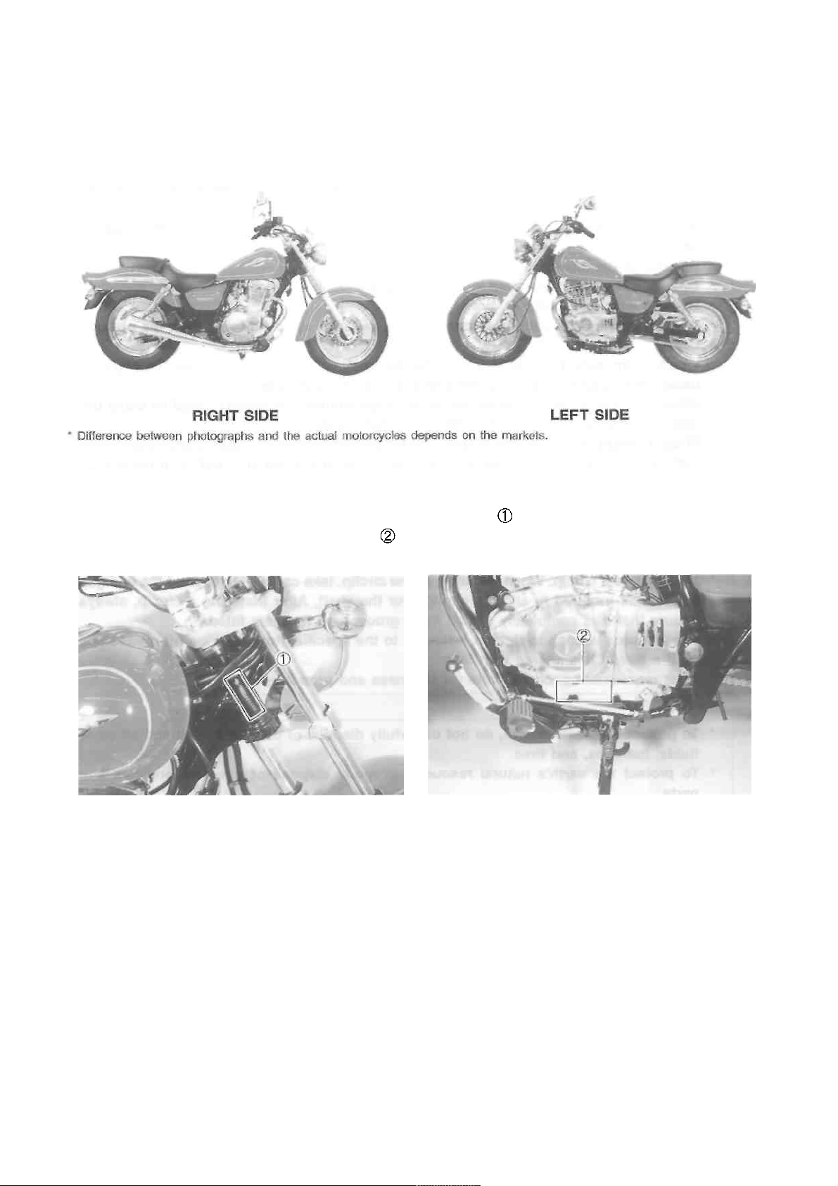
SUZUKI GZ250X ('99-MODEL)
SERIAL NUMBER LOCATION
The frame serial number or V.I.N. (Vehicle Identification Number) is stamped on the right side of the
steering head pipe. The engine serial number is located on the left side of the crankcase. These
numbers are required especially for registering the machine and ordering spare parts.
FUEL AND OIL RECOMMENDATIONS
FUEL
Use unleaded gasoline that is graded 91 octane or higher.
Page 10
GENERAL INFORMATION 1-4
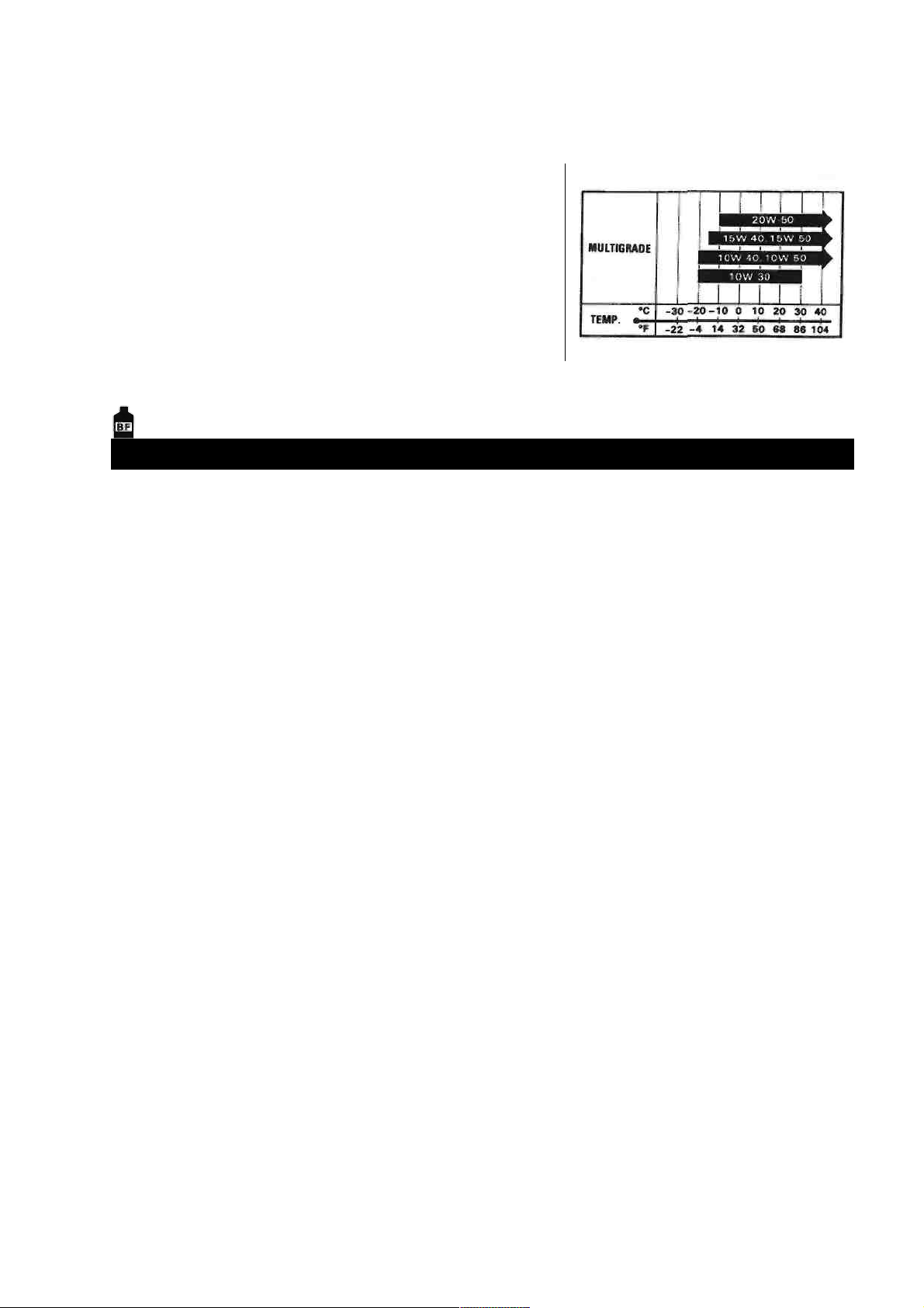
ENGINE OIL
Use only oils which are rated SF or SG under the API classification. The recommended viscosity is SAE 10W/40. If
SAE 10W/40 engine oil is not available, select an alternative according to the chart.
BRAKE FLUID
Specification and classification: DOT 4
WARNING
This motorcycle uses a glycol-based brake fluid. Do not use or mix different types of
brake fluid such as silicone-based and petroleum-based fluids for refilling the system,
otherwise serious damage will result to the brake system.
Never use any brake fluid taken from old, used or unsealed containers.
Never re-use brake fluid left over from a last servicing or which has been stored for a long
period of time.
FRONT FORK OIL
Use SUZUKI fork oil SS-08 (#10).
BREAK-IN PROCEDURES
During manufacturing only the best possible materials are used and all machined parts are finished to
a very high standard. It is still necessary to allow the moving parts to "BREAK-IN" before subjecting the
engine to maximum stresses. The future performance and reliability of the engine depends on the care
and restraint exercised during its early life. The general rules are as follows.
• Keep to this break-in throttle position.
Initial 800 km (500 miles) : Less than 1/2 throttle
Up to 1 600 km (1 000 miles): Less than 3/4 throttle
• Upon reaching an odometer reading of 1 600 km you can subject the motorcycle to full throttle
operation for short periods of time.
Page 11
Page 12

GENERAL INFORMATION 1-6
SPECIFICATIONS
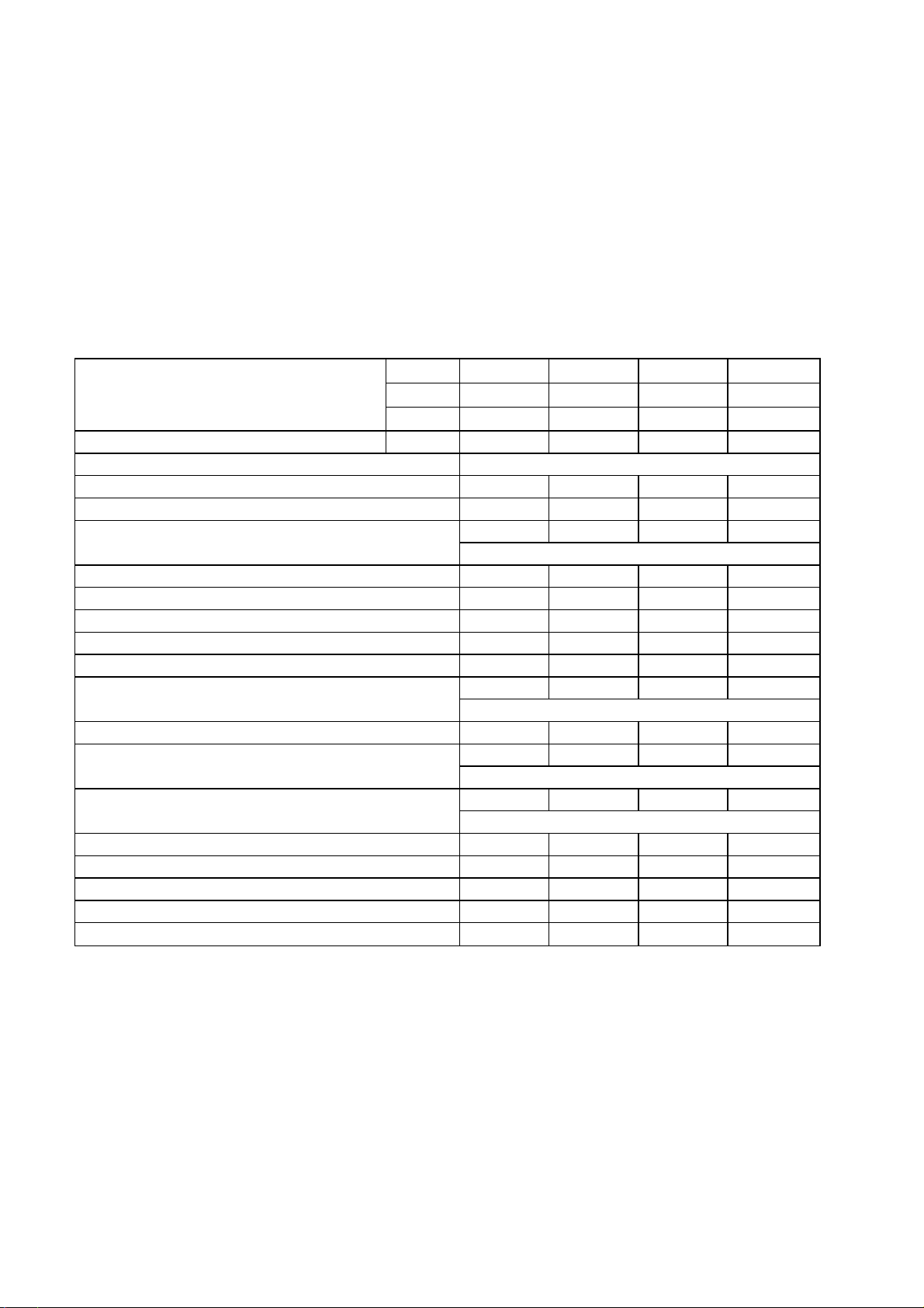
DIMENSIONS AND DRY MASS
Overall length .............................................
Overall width ................................................
Overall height ..............................................
Wheelbase ....................................................
Ground clearance .........................................
Seat height ....................................................
Dry mass .....................................................
ENGINE
Type ..............................................................
Number of cylinder ........................................
Bore ...............................................................
Stroke ...........................................................
Displacement ................................................
Compression ratio .........................................
Carburetor ...................................................
Air cleaner .....................................................
Starter system ...............................................
Lubrication system .......................................
TRANSMISSION
Clutch ...........................................................
Transmission ...............................................
Gearshift pattern ............................................
Primary reduction ratio ...............................
Final reduction ratio ......................................
Gear ratios, Low .........................................
2nd ........................................
3rd ..........................................
4th ..........................................
Top .......................................
Drive chain ...................................................
2 160 mm (85.0 in)
815 mm (32.1 in)
1 090 mm (42.9 in)
1 450 mm (57.1 in)
125 mm ( 4.9 in)
680 mm (27.8 in)
137 kg (302 lbs)
Four-stroke, air-cooled, OHC
1
72.0 mm (2.835 in)
61.2 mm (2.409 in)
249 cm3 (15.2 cu. in)
9.0 : 1
MIKUNI BSR32SS, single
Non-woven fabric element
Electric
Wet sump
Wet multi-plate type
5-speed constant mesh
1-down, 4-up
3.238 (68/21)
2.733 (41/15)
2.636 (29/11)
1.687 (27/16)
1.263 (24/19)
1.000 (20/20)
0.818 (18/22)
DID 520VC5, 110 links
Page 13

1-7 GENERAL INFORMATION
ELECTRICAL
Ignition type .............................................................. Electronic ignition (Transistorized)
Ignition timing ........................................................ 10° B.T.D.C. at 1 300 r/min
Spark plug .............................................................. NGK DR8EA or DENSO X24ESR-U
Battery ...................................................................... 12V 21.6 kC (6 Ah)/10 HR
Generator ................................................................. Three-phase A.C. generator
Fuse ......................................................................... 20/15/15/15/10/10A
Headlight .................................................................. 12V 60/55W
Position light .......................................................... 12V 4W ....... Except for E-03, -24, -28, -33
Brake light/Taillight .................................................. 12V 21/5W
Front turn signal light/Running light .......................... 12V 21/5W ....... E-03, -28, -33
Turn signal light ..................................................... 12V 21W
Speedometer light .................................................... 12V 1.7W
Neutral indicator light ................................................ 12V 3.4W
Turn signal indicator light ......................................... 12V 3.4W
High beam indicator light ........................................ 12V 1.7W
CHASSIS
Front suspension ................................................... Telescopic, coil spring, oil damped
Rear suspension ...................................................... Swingarm type, coil spring, oil damped, spring
preload 5-way adjustable
Front fork stroke ....................................................... 120 mm (4.7 in)
Rear wheel travel ..................................................... 90 mm (3.5 in)
Steering angle .......................................................... 40° (right and left)
Caster ...................................................................... 32° 30'
Trail ......................................................................... 140 mm (5.5 in)
Turning radius .......................................................... 2.6 m (8.5 ft)
Front brake ............................................................... Disc brake
Rear brake ................................................................ Internal expanding
Front tire size .......................................................... 110/90-16 59P
Rear tire size ............................................................ 130/90-15M/C 66P
CAPACITIES
Fuel tank, including reserve ..................................... 14 L (3.7/3.1 US/Imp gal)
reserve ................................................ 2.9 L (0.8/0.6 US/Imp gal)
Engine oil, oil change ........................................... 1 300 ml (1.4/1.1 US/Imp qt)
with filter change ................................ 1 400 ml (1.5/1.2 US/Imp qt)
overhaul ............................................. 1 700 ml (1.8/1.5 US/Imp qt)
Front fork oil (each leg) ......................................... 369 ml (12.5/13.0 US/Imp oz)
Specifications are subject to change without notice.
Page 14

GENERAL INFORMATION 1-8
COUNTRY AND AREA CODES
The following codes stand for the applicable country(-ies) and area(-s).
CODE
COUNTRY OR AREA
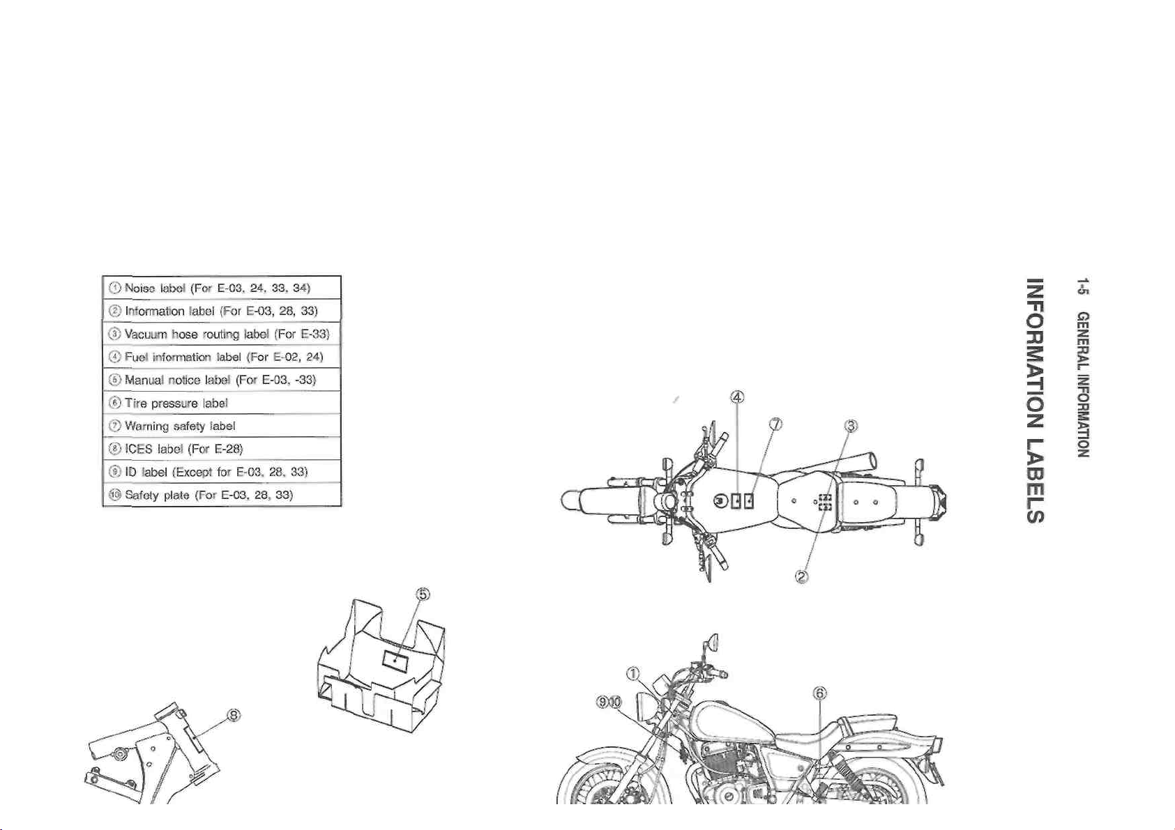
E-01
General
E-02
UK
E-03
U.S.A. (Except for California)
E-04
France
E-17
Sweden, Finland (E-15), Norway (E-16), Denmark (E-26)
E-22
Germany
E-24
Australia
E-25
Netherlands
E-28
Canada
E-33
California (U.S.A.)
E-34
Italy, Belgium (E-21), Spain (E-53)
Page 15

PERIODIC MAINTENANCE
----------------------------------------- CONTENTS ------------------------------------------
PERIODIC MAINTENANCE SCHEDULE ............................................. 2- 1
PERIODIC MAINTENANCE CHART ................................................ 2- 1
LUBRICATION POINTS ................................................................. 2-2
MAINTENANCE AND TUNE-UP PROCEDURES .............................. 2-3
EXHAUST PIPE BOLTS AND MUFFLER MOUNTING BOLTS ......... 2-3
AIR CLEANER ................................................................................ 2- 3
VALVE CLEARANCE ..................................................................... 2-4
SPARK PLUG ................................................................................. 2- 6
FUEL HOSE .................................................................................... 2- 7
ENGINE IDLE SPEED ..................................................................... 2- 7
THROTTLE CABLE PLAY ............................................................... 2- 7
STARTER PLUNGER CABLE PLAY ............................................... 2-9
CLUTCH .......................................................................................... 2-9
ENGINE OIL AND OIL FILTER ........................................................ 2- 9
DRIVE CHAIN .................................................................................. 2-70
BRAKES .......................................................................................... 2-12
TIRE ............................................................................................... 2-15
STEERING ....................................................................................... 2-15
FRONT FORK ................................................................................. 2-16
REAR SUSPENSION ....................................................................... 2-16
CHASSIS BOLTS AND NUTS ......................................................... 2-16
COMPRESSION PRESSURE CHECK ............................................... 2-18
OIL PRESSURE CHECK .................................................................... 2-19
Page 16
2-1 PERIODIC MAINTENANCE
PERIODIC MAINTENANCE SCHEDULE
The chart below lists the recommended intervals for all the required periodic service work necessary to
keep the motorcycle operating at peak performance and economy. Maintenance intervals are expressed in terms of kilometers and months, and are dependant on whichever comes first.
NOTE:
More frequent servicing may be performed on motorcycles that are used under severe conditions.
PERIODIC MAINTENANCE CHART
Interval
Item
km
1 000
5 000
10 000
15 000
miles
600
3 000
6 000
9 500
months 3 15
30
45
Exhaust pipe bolts and muffler mounting
bolts - T T T
Air cleaner element
Clean every 3 000 km (2 000 miles).
Valve clearance
I I I
I
Spark plug
- I R
I
Fuel hose
- I I
I
Replace every 4 years.
Engine idle speed
I I I
I
Throttle cable play
I I I
I
Clutch - I I I
Engine oil
R R R
R
Engine oil filter
R - R
-
Drive chain
I I I
I
Clean and lubricate every 1 000 km (600 miles).
Brakes
I I I
I
Brake hose
- I I
I
Replace every 4 years.
Brake fluid
- I I
I
Replace every 2 years.
Tires - I I I
Steering
I - I
-
Front fork
- - I
-
Rear suspension
- - I
-
Chassis bolts and nuts
T T T
T
NOTE:
I: Inspection and adjust, clean, lubricate or replace as necessary
C: Clean R: Replace T: Tighten
Page 17
PERIODIC MAINTENANCE 2-2
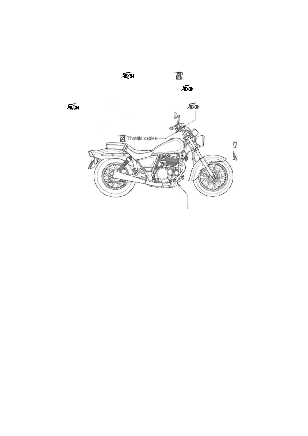
LUBRICATION POINTS
Proper lubrication is important for smooth operation and long life of each working part of the motorcycle. Major lubrication points are indicated below.
Side-stand pivot Drive chain
and spring hook
Brake pedal pivot
NOTE:
* Before lubricating each part, clean off any rusty spots and wipe off any grease, oil, dirt or grime.
* Lubricate exposed parts which are subject to rust, with a rust preventative spray especially whenever
the motorcycle has been operated under wet or rainy condition.
Clutch lever holder
Brake lever holder
Page 18
2-3 PERIODIC MAINTENANCE
MAINTENANCE AND TUNE-UP PROCEDURES
This section describes the servicing procedures for each
item in the Periodic Maintenance chart.
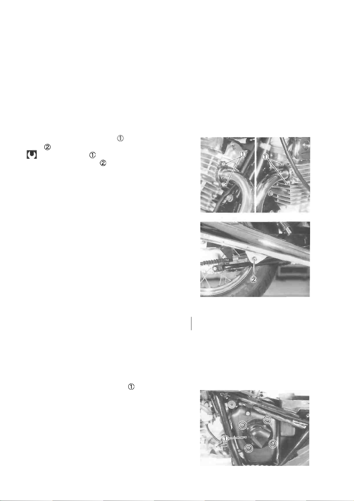
EXHAUST PIPE BOLTS AND MUFFLER
MOUNTING BOLTS
Tighten every 5 000 km (3 000 miles, 15 months).
• Tighten the exhaust pipe bolts and muffler mounting
bolt to the specified torque.
Exhaust pipe bolt : 14 N ■ m (1.4 kg-m, 10.0 Ib-ft)
Muffler mounting bolt : 29 N ■ m (2.9 kg-m, 21.0 Ib-ft)
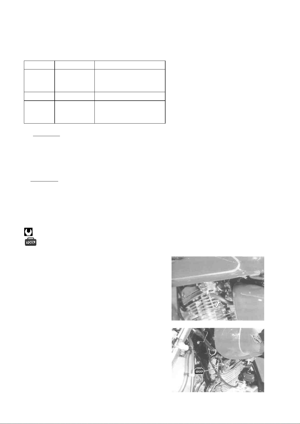
AIR CLEANER
Clean every 3 000 km (2 000 miles).
If the air cleaner is clogged with dust, intake resistance will
increase, resulting in a decrease in engine output and an
increase in fuel consumption. Check and clean the air
cleaner element in the following manner.
• Remove the front seat. (See p. 5-1.)
• Remove the left frame cover. (See p. 5-1.)
• Remove the air cleaner element .
Page 19
PERIODIC MAINTENANCE 2-4
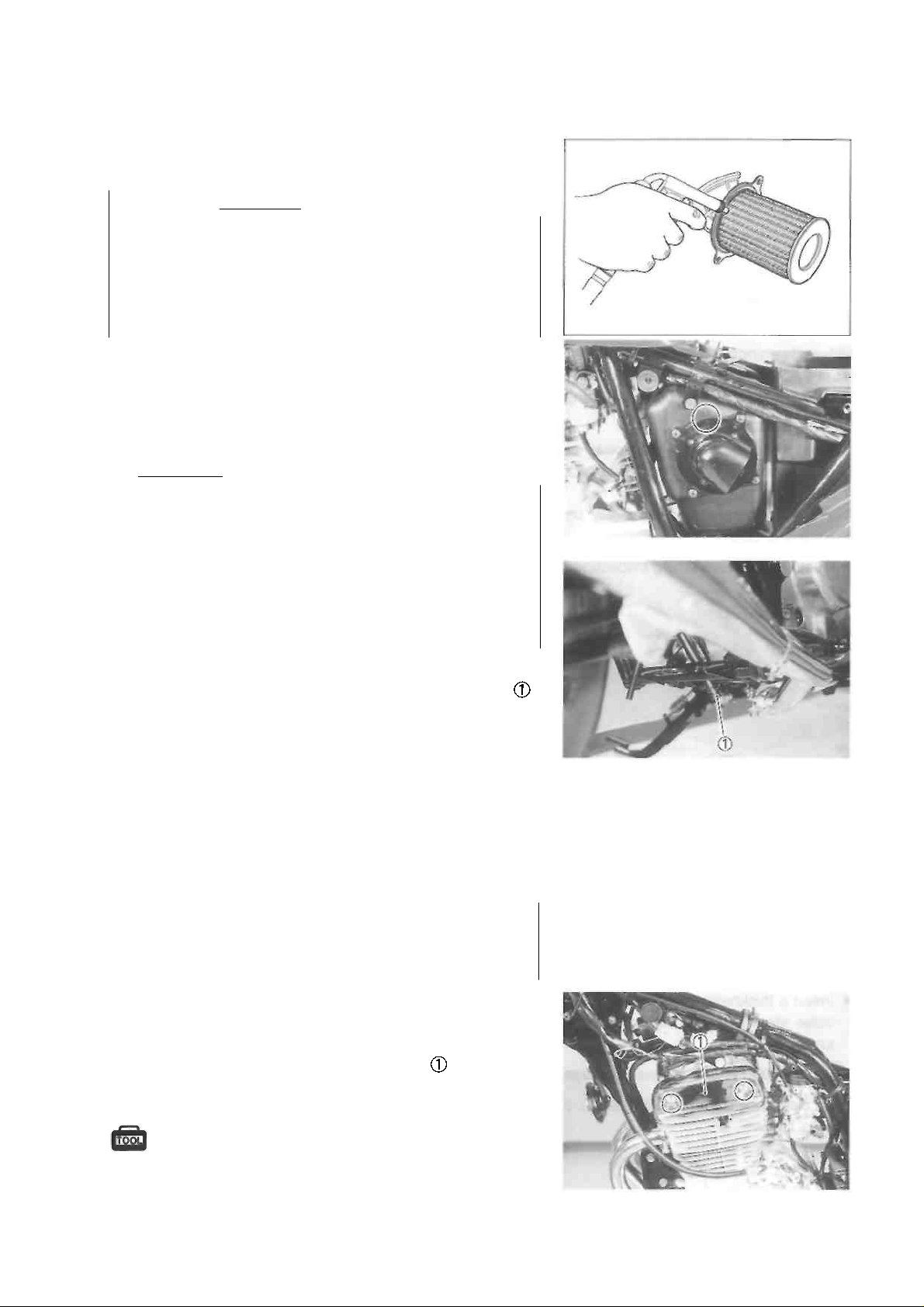
• Carefully use compressed air to clean the air cleaner
element.
CAUTION ________________________________
Always apply compressed air to the
outside of the air cleaner element. If compressed
air is applied to the inside, dirt will be forced into
the pores of the air cleaner element, restricting
air flow through the air cleaner element.
• Reinstall the cleaned or new air cleaner element in the
reverse order of removal.
• When installing the air cleaner element into the air cleaner case, align the triangle marks on the air cleaner element and the air cleaner case.
CAUTION
If driving under dusty conditions, clean the air
cleaner element more frequently. The surest way
to accelerate engine wear is to operate the engine
without the element or to use a torn element.
Make sure that the air cleaner is in good condition
at all times. The life of the engine depends largely
on this component!
NOTE:
When cleaning the air cleaner element, remove the plug
and drain any water from the air cleaner drain hose.
VALVE CLEARANCE
Inspect initially at 1 000 km (600 miles, 3 months)
and every 5 000 km (3 000 miles, 15 months) thereafter.
INSPECTION
• Remove the front seat. (See p. 5-1.)
• Remove the fuel tank. (See p. 4-1.)
• Remove the cylinder head cover left cap
• Disconnect the spark plug cap and remove the spark
plug.
09930-10121: Spark plug socket wrench set
CAUTION
Page 20
2-5 PERIODIC MAINTENANCE
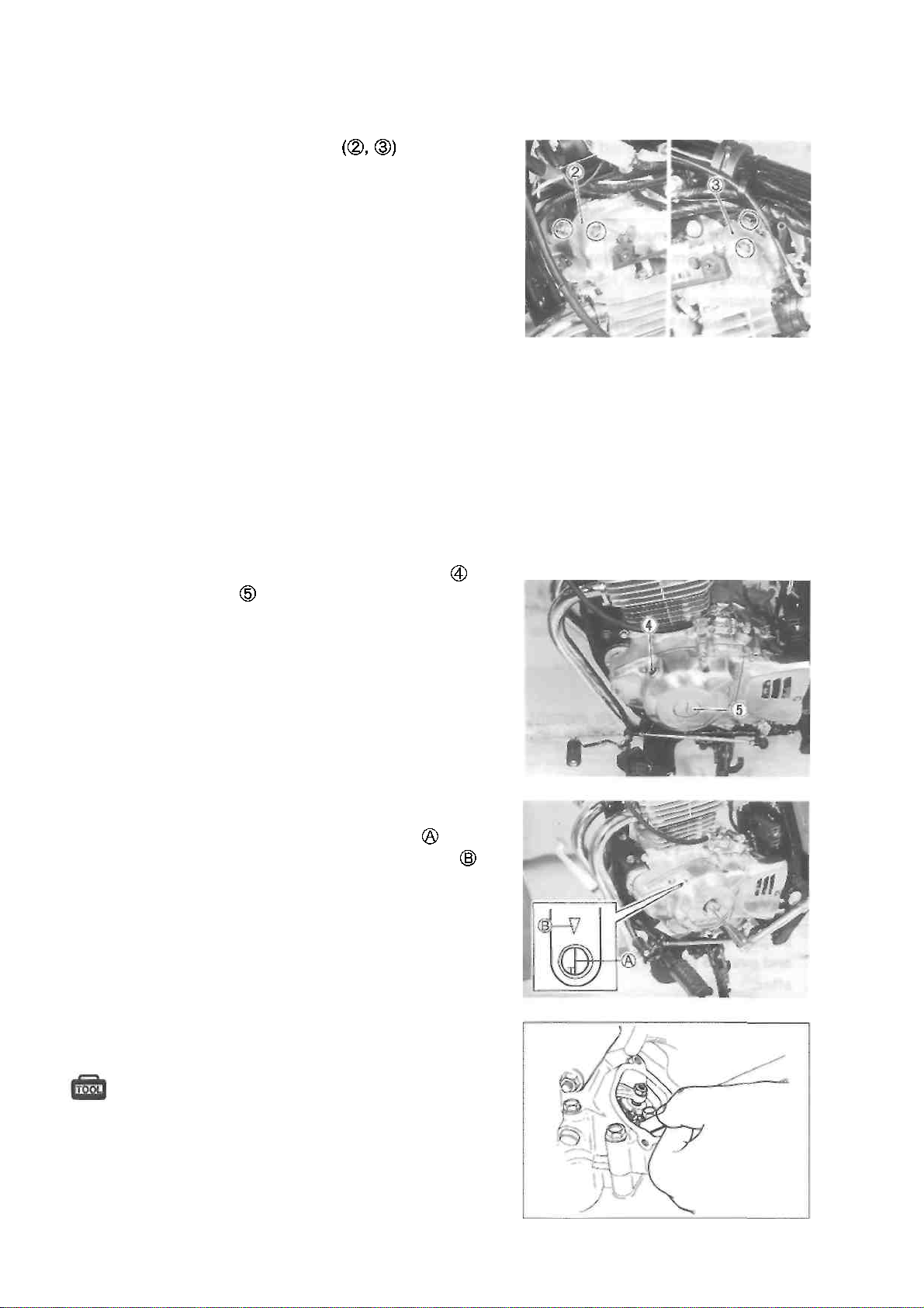
Remove the valve inspection caps
The valve clearance specification is different for intake and
exhaust valves.
Valve clearance adjustment must be checked and adjusted,
1) at the time of periodic inspection, 2) when the valve
mechanism is serviced, and 3) when the camshaft is removed for servicing.
Valve clearance (when cold):
IN. : 0.03-0.08 mm (0.001-0.003 in)
EX.: 0.08-0.13 mm (0.003-0.005 in)
NOTE:
* The piston must be at top dead center (TDC) on the
compression stroke in order to check or adjust the valve
clearance.
* The valve clearance should only be checked when the
engine is cold.
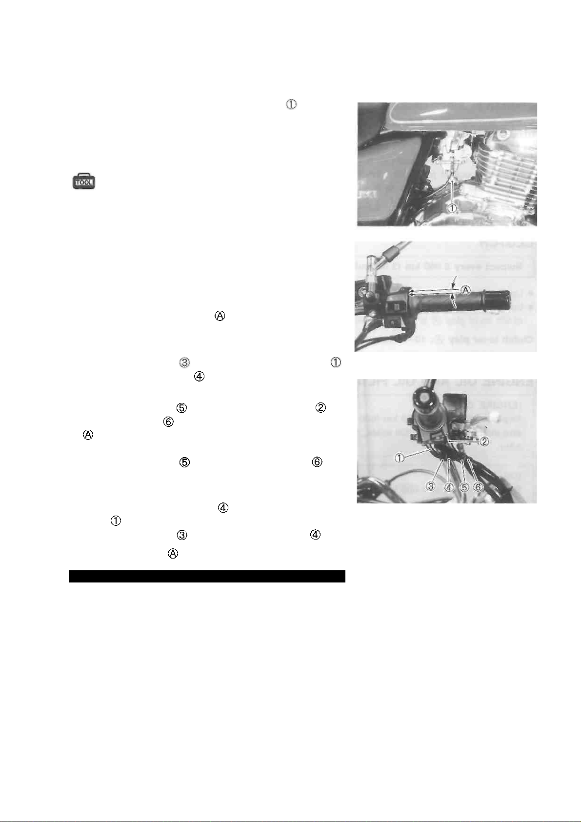
* Remove the valve timing inspection plug and
generator cover cap
Rotate the crankshaft with a box wrench to set the piston
at top dead center (TDC) on the compression stroke.
(Rotate the crankshaft until the "T" line on the
generator rotor is aligned with the triangle mark on
the generator cover.)
Insert a thickness gauge into the clearance between the
valve stem end and the adjusting screw on the rocker
arm.
09900-20803: Thickness gauge
If the clearance is out of specification, adjust it to specification as follows.
Page 21

PERIODIC MAINTENANCE 2-6
ADJUSTMENT
The clearance is adjusted using the special tool and offset
wrench.
• Loosen the locknuts
• Insert a thickness gauge between the valve stem end
and the adjusting screw on the rocker arm.
• Adjust the valve clearance by turning the adjusting screw
using the special tool while holding the locknuts
09917-14920: Valve adjuster wrench
CAUTION
Both the right and left valve clearances should be as
closely as possible.
• After the adjustment is completed, tighten the locknut securely.
• Rotate the crankshaft 720° with a box wrench and check
that the clearance is within specification.
SPARK PLUG
Inspect every 5 000 km (3 000 miles, 15 months).
Replace every 10 000 km (6 000 miles, 30 months).
Neglecting the spark plug eventually leads to difficult starting and poor engine performance. If the spark plug is used
for a long period, the electrode gradually bums away and
carbon builds up along the inside part of the spark plug. In
accordance with the Periodic Maintenance chart, the spark
plug should be inspected, cleaned and regapped at the recommended intervals.
• Remove the cylinder head cover left cap.
• Disconnect the spark plug cap and remove the spark
plug.
09930-10121: Spark plug socket wrench set
• Carbon deposits on the spark plug will prevent
good
sparking and may cause the engine to misfire. Be sure to
clean the carbon deposits off periodically.
If the center electrode is fairly worn down, the spark plug
should be replaced and the spark plug gap set to the specification using a thickness gauge.
09900-20803: Thickness gauge
Spark plug gap: 0.6-0.7 mm (0.024-0.028 in)
Page 22
2-7 PERIODIC MAINTENANCE
Check the spark plug for burns. If any abnormalities are
found, replace the spark plug as indicated below.
NGK
DENSO
Remarks
DR7EA
X22ESR-U
If the standard spark plug is
apt to get wet, replace with
this plug.
DR8EA
X24ESR-U
Standard
DR9EA
X27ESR-U
If the standard spark plug is
apt to overheat, replace with
this plug.
CAUTION
Confirm the thread size and reach when replacing
the spark plug. If the reach is too short, carbon
will be deposited on the screw portion of the plug
hole and engine damage may result.
CAUTION
Before using a spark plug wrench, carefully turn
the spark plug by finger into the threads of the
cylinder head to prevent damage.
• Tighten the spark plug to the specified torque using the
special tool.
Spark plug: 18 N-m (1.8 kg-m, 13.0 Ib-ft)
09930-10121: Spark plug socket wrench set
FUEL HOSE
Inspect every 5 000 km (3 000 miles, 15 months).
Replace every 4 years.
ENGINE IDLE SPEED
Inspect initially at 1 000 km (600 miles, 3 months)
and every 5 000 km (3 000 miles, 15 months) thereafter.
• Adjust the throttle cable play. (See p. 2-8.)
• Warm up the engine.
NOTE:
Make this adjustment when the engine is hot.
• Connect an electric tachometer to the high tension cord.
Page 23
PERIODIC MAINTENANCE 2-8
• Start the engine, turn the throttle stop screw and set
the engine idle speed as follows.
Engine idle speed:
1 300 ± 50 r/min .... For E-03, -28, -33
1 300 ±100 r/min ..... For the others
09900-26006: Tachometer
THROTTLE CABLE PLAY
Inspect initially at 1 000 km (600 miles, 3 months)
and every 5 000 km (3 000 miles, 15 months) thereafter.
Adjust the throttle cable play
steps.
First step:
• Loosen the lock nut of the throttle returning cable
and turn in the adjuster fully into the threads.
Second step:
• Loosen the lock nut of the throttle pulling cable
• Turn the adjuster in or out until the throttle cable play
should be 2.0-4.0 mm (0.08-0.16 in) at the throttle
grip.
• Tighten the lock nut while holding the adjuster
Third step:
• While holding the throttle grip at the fully closed position,
slowly turn out the adjuster of the throttle returning
cable to feel resistance.
• Tighten the lock nut while holding the adjuster
Throttle cable play : 2.0-4.0 mm (0.08-0.16 in)
WARNING
After the adjustment is completed, check that
handlebar movement does not raise the engine
idle speed and that the throttle grip returns
smoothly and automatically.
NOTE:
Major adjustment can be made by the carburetor side adjuster.
with the following three
Page 24
2-9 PERIODIC MAINTENANCE
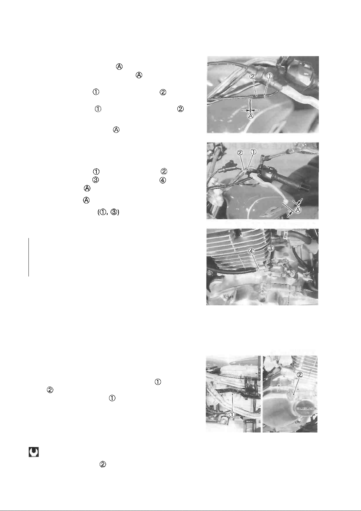
STARTER PLUNGER CABLE PLAY
Starter plunger cable play
should be 0.5-1.0 mm
(0.02-0.04 in) as shown. If the play is incorrect, adjust
it as follows:
• Loosen the lock nut and turn the adjuster in or out
until the specified play is obtained.
• Tighten the lock nut while holding the adjuster
Starter plunger cable play
CLUTCH
Inspect every 5 000 km (3 000 miles, 15 months).
• Loosen the lock nut and turn the adjuster fully in.
• Loosen the lock nut and turn the adjuster until the
clutch lever play is within specification.
Clutch lever play : 10-15 mm (0.4-0.6 in)
• Tighten the lock nuts
ENGINE OIL AND OIL FILTER
(ENGINE OIL)
Replace initially at 1 000 km (600 miles, 3 months)
and every 5 000 km (3 000 miles, 15 months) thereafter.
(OIL FILTER)
Replace initially at 1 000 km (600 miles, 3 months)
and every 10 000 km (6 000 miles, 30 months)
thereafter.
The engine oil should be changed while the engine is
warm. Oil filter replacement at the above intervals should
be done together with the engine oil change.
ENGINE OIL REPLACEMENT
• Keep the motorcycle upright.
• Place an oil pan below the engine, and drain the engine
oil by removing the engine oil drain plug and oil filler
cap .
• Tighten the oil drain plug to the specified torque, and
pour new oil through the oil filler. When performing an oil
change (without oil filter replacement), the engine will
hold about 1 300 ml (1.4/1.1 US/Imp qt) of oil. Use SF or
SG classified (API) engine oil with a viscosity rating of
10W-40 (SAE).
Oil drain plug: 28 N-m (2.8 kg-m, 20.0 Ib-ft)
• Install the oil filler cap
0.5-1.0 mm
(0.02-0.04 in)
Page 25
PERIODIC MAINTENANCE 2-10
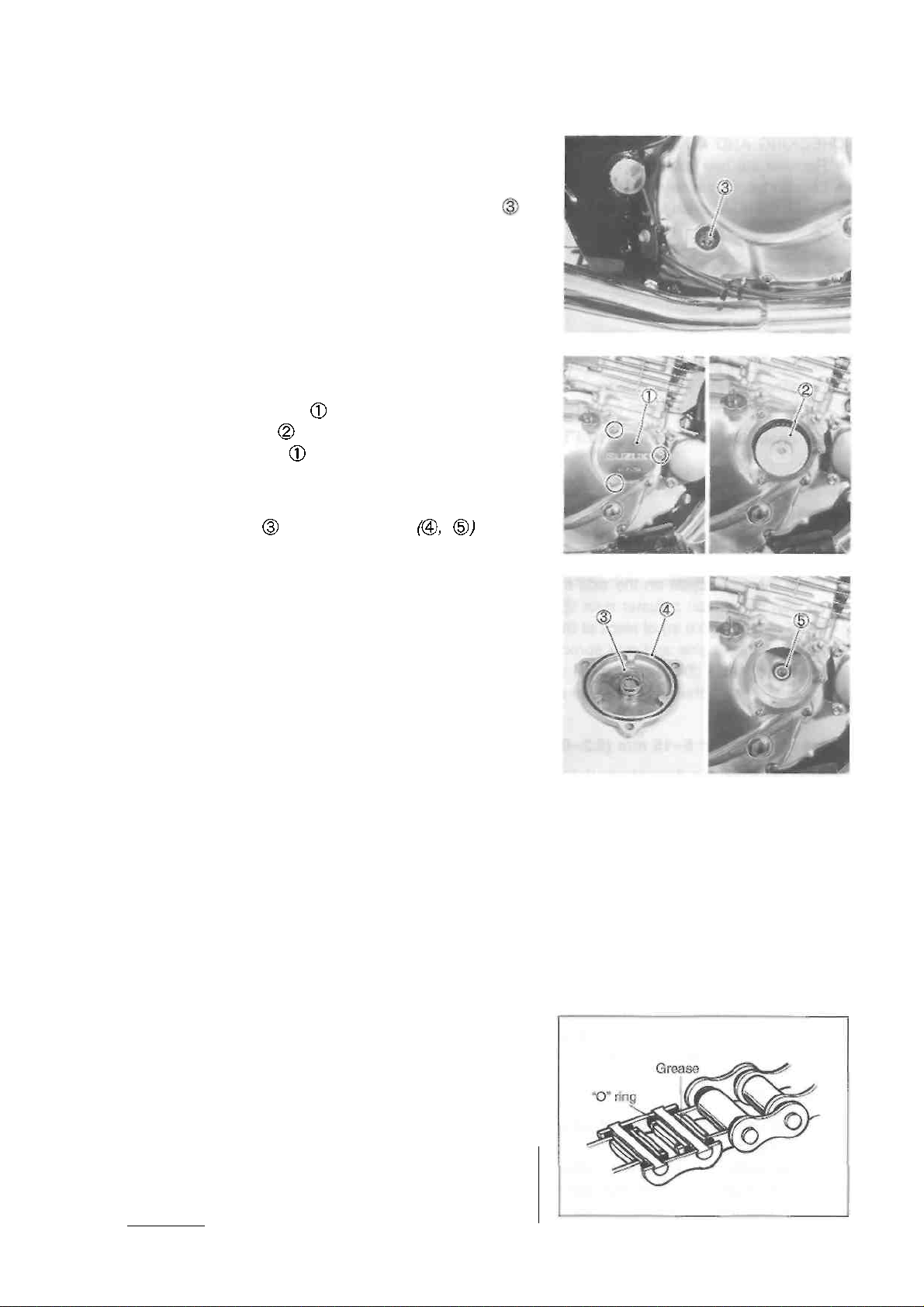
• Start up the engine and allow it to run for a few minutes
at idling speed.
• Turn off the engine and wait about one minute, then
check the oil level through the inspection window . If
the level is below the "F" mark, add oil to the proper
level.
OIL FILTER REPLACEMENT
• Drain the engine oil as described in the engine oil replacement procedure.
• Remove the oil filter cap by removing the nuts.
• Remove the oil filter and install a new one.
• Install the oil filter cap and tighten the nuts securely.
NOTE:
Before installing the new oil filter and oil filter cap, make
sure that the spring and new O-rings
are
installed correctly.
• Add new engine oil and check the oil level as described
in the engine oil replacement procedure.
Oil viscosity and classification:
10W/40 (SAE)/SF or SG (API)
NECESSARY AMOUNT OF ENGINE OIL
Oil change : 1 300 ml (1.4/1.1 US/Imp qt)
Oil and filter change: 1 400 ml (1.5/1.2 US/Imp qt)
Engine overhaul : 1 700 ml (1.8/1.5 US/Imp qt)
DRIVE CHAIN
Inspect initially at 1 000 km (600 miles, 3 months)
and every 5 000 km (3 000 miles, 15 months) thereafter. Clean and lubricate every 1 000 km (600
miles).
Visually inspect the drive chain for the possible defects
listed below. (Support the motorcycle by a jack and a
wooden block, turn the rear wheel slowly by hand with the
transmission shifted to Neutral.)
• Loose pins * Excessive wear
• Damaged rollers * Kinked or binding links
• Dry or rusted links * Missing O-ring seals
• Twisted or seized links
If any defects are found, the drive chain must be replaced.
CAUTION __________________________________
The standard drive chain is DID520VC5. SUZUKI
recommends to use this standard drive chain as a
replacement.
Page 26

replacement.
Page 27
2-11 PERIODIC MAINTENANCE
CHECKING AND ADJUSTING
• Remove the rear axle cotter pin. (For E-28 model)
• Loosen the rear axle nut
• Tense the drive chain fully by turning chain adjuster nuts
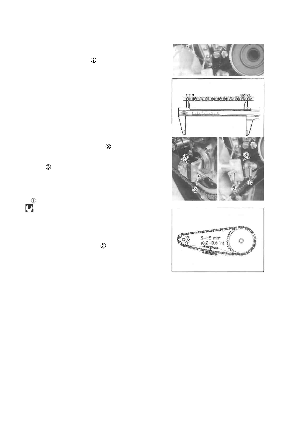
• Count out 21 pins (20-pitch) on the chain measure the
distance between the two points. If the distance exceeds
the service limit, the chain must be replaced.
Drive chain 20-pitch length: 319.4 mm (12.57 in)
NOTE:
When replacing the drive chain, replace the drive chain and
sprockets as a set.
• Place the motorcycle on the side-stand.
• Loosen both chain adjuster nuts until the chain has 5-15
mm (0.2-0.6 in) of slack at the middle of the chain between
the engine and rear sprockets as shown. The reference
marks must be at the same position on the scale to
ensure that the front and rear wheels are correctly aligned.
Drive chain slack: 5-15 mm (0.2-0.6 in)
• After adjusting the drive chain, tighten the rear axle nut
to the specified torque.
Rear axle nut:
65 N-m (6.5 kg-m, 47.0 Ib-ft) ........ For E-03, -28, -33
78 N-m (7.8 kg-m, 56.5 Ib-ft) ........ For the others
• Recheck the chain slack after tightening the axle nut and
readjust if necessary.
* Tighten both chain adjuster nuts securely.
• Install the new cotter pin. (For E-03, -28, -33 models)
CLEANING AND LUBRICATING
• Clean the drive chain with kerosine. If the drive chain
tends to rust quickly, the intervals must be shortened.
CAUTION
Do not use trichloroethylene, gasoline or any similar solvent.
These fluids have too great a dissolving power for
this chain and they can damage the O-rings. Use
only kerosine to clean the drive chain.
Page 28
PERIODIC MAINTENANCE 2-12
• After cleaning and drying the chain, oil it with a heavyweight engine oil.
CAUTION
Do not use any oil sold commercially as "drive
chain oil", this type of oil can such oil can damage
the "0"-rings (or seals).
BRAKES
(BRAKE)
Inspect initially at 1 000 km (600 miles, 3 months)
and every 5 000 km (3 000 miles, 15 months) thereafter.
(BRAKE HOSE AND BRAKE FLUID)
Inspect every 5 000 km (3 000 miles, 15 months).
Replace hose every 4 years. Replace fluid every 2
years.
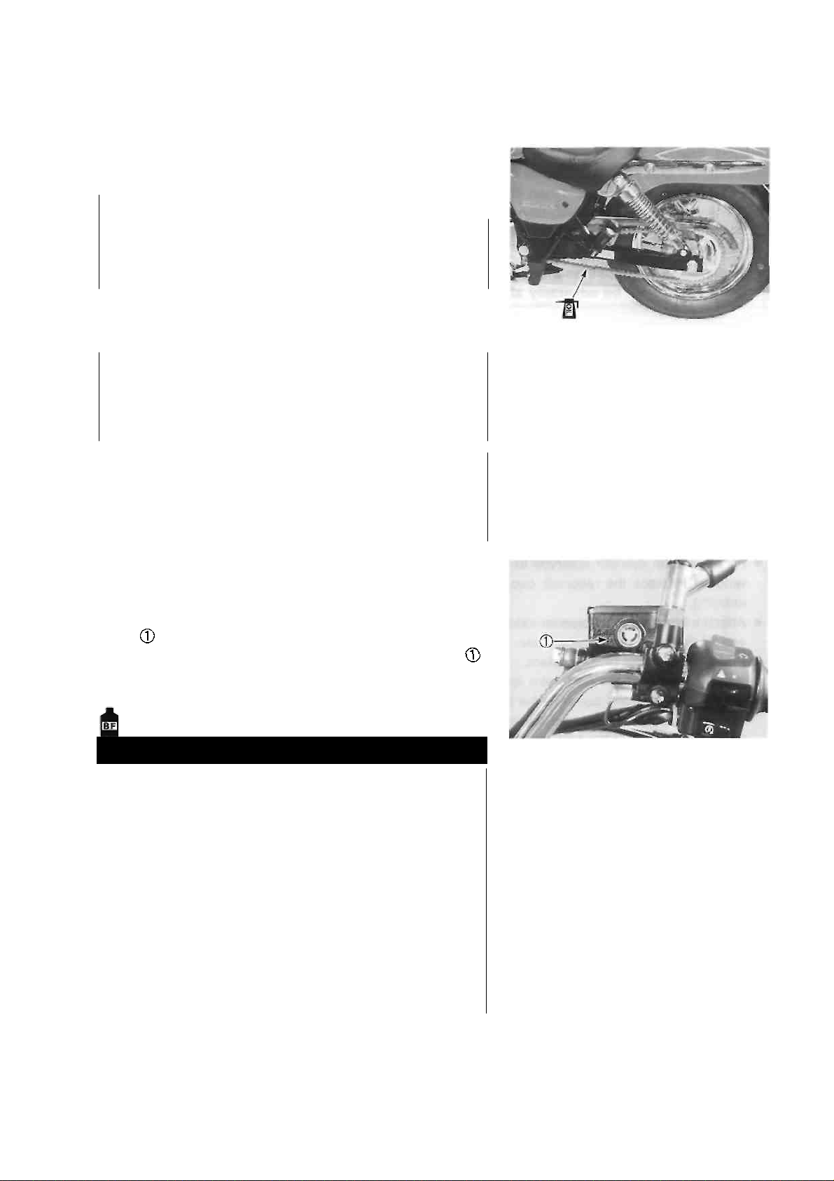
BRAKE FLUID LEVEL
• Keep the motorcycle upright and place the handlebars
straight.
• Check the brake fluid level by observing the lower limit
line on the front brake fluid reservoir.
• When the brake fluid level is below the lower limit line
replenish with brake fluid that meets the following specification.
Specification and classification: DOT 4
WARNING
The brake system of this motorcycle is filled
with a glycol-based brake fluid. Do not use or
mix different types of fluid such as siliconebased and petroleum-based fluids. Do not use
any brake fluid taken from old, used or unsealed containers. Never re-use brake fluid left
over from the last servicing or stored for a long
period of time.
Brake fluid, if it leaks, will interfere with safe
running and immediately discolor painted surfaces. Check the brake hose and hose joints for
cracks and oil leakage.
Page 29
2-13 PERIODIC MAINTENANCE
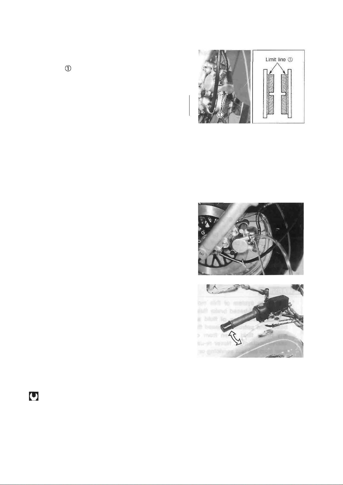
FRONT BRAKE PADS
The extent of brake pad wear can be checked by observing
the limit line on the pad. When the wear exceeds the
limit line, replace the pads with new ones. (See p. 5-8.)
A CAUTION
Replace the brake pad as a set, otherwise braking
performance will be adversely affected.
AIR BLEEDING THE BRAKE FLUID CIRCUIT
Air trapped in the brake fluid circuit acts like a cushion to
absorb a large proportion of the pressure developed by the
master cylinder and thus interferes with the full braking performance of the brake caliper. The presence of air is indicated by "sponginess" of the brake lever and also by lack
of braking force. Considering the danger to which such
trapped air exposes the machine and rider, it is essential
that, after remounting the brake and restoring the brake
system to the normal condition, the brake fluid circuit be
purged of air in the following manner:
• Fill the master cylinder reservoir to top of the inspection
window. Replace the reservoir cap to prevent dirt from
entering.
• Attach a hose to the air bleeder valve, and insert the free
end of the hose into a receptacle.
• Bleed air from the brake system.
• Squeeze and release the brake lever several times in
rapid succession and squeeze the lever fully without releasing it. Loosen the bleeder valve by turning it a quarter of a turn so that the brake fluid runs into the receptacle, this will remove the tension of the brake lever
causing it to touch the handlebar grip. Then, close the air
bleeder valve, pump and squeeze the brake lever, and
open the valve. Repeat this process until the fluid flowing
into the receptacle no longer contains air bubbles.
NOTE:
While bleeding the brake system, replenish the brake fluid
in the reservoir as necessary. Make sure that there is always some fluid visible in the reservoir.
• Close the air bleeder valve, and disconnect the hose. Fill
the reservoir with brake fluid to the top of the inspection
window.
Air bleeder valve: 7.5 N ■ m (0.75 kg-m, 5.5 Ib-ft)
A CAUTION
Handle brake fluid with care: the fluid reacts
chemically with paint, plastics, rubber materials,
etc.
Page 30
PERIODIC MAINTENANCE 2-14
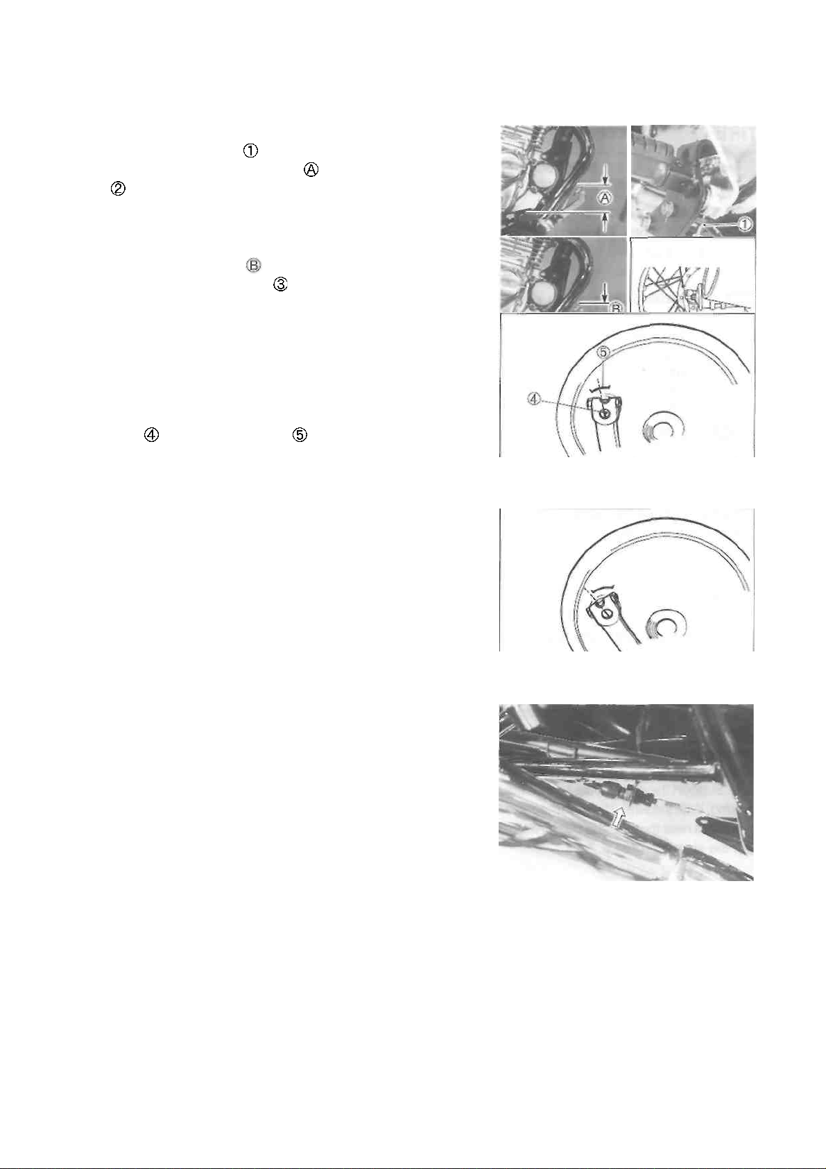
REAR BRAKE PEDAL HEIGHT
• Loosen the lock nut
• Adjust the brake pedal height by turning the adjuster
to locate the pedal 50 mm (2.0 in) above the top face
of the footrest.
REAR BRAKE ADJUSTING
• Adjust the free travel to 20-30 mm (0.8-1.2 in) by
turning the adjusting nut
REAR BRAKE SHOE WEAR
This motorcycle is equipped with brake lining wear limit
indicator on the rear brake.
To check brake lining wear, perform the following steps.
• Make sure that the rear brake is properly adjusted.
• Depress the rear brake pedal. Make sure that the index
mark is within the range embossed on the brake
panel.
• If the index mark goes beyond the range, the brake shoe
assembly should be replaced with a new set of shoes.
The extension line of the index mark is within
the range.
The extension line of the index mark is out of
the ranae.
BRAKE LIGHT SWITCH
Adjust the rear brake light switch so that the brake light will
come on just before pressure is felt when the brake pedal
is depressed.
Page 31

2-15 PERIODIC MAINTENANCE
TIRE
Inspect every 5 000 km (3 000 miles, 15 months).
TIRE TREAD CONDITION
Operating the motorcycle with excessively worn tires will
decrease riding stability and consequently invite a dangerous situation. It is highly recommended to replace a tire
when the remaining depth of tire tread reaches the following specification.
Tire tread depth limit (front): 1.6 mm (0.06 in)
(rear) : 2.0 mm (0.08 in)
09900-20805: Tire depth gauge
TIRE PRESSURE
If the tire pressure is too high or too low, steering will be
adversely affected and tire wear increased. Therefore,
maintain the correct tire pressure for good roadability and a
longer tire life. Cold inflation tire pressure is as follows.
COLD INFLATION
TIRE PRESSURE
SOLO RIDING
DUAL RIDING
kPa
kg/cm2
psi
kPa
kg/cm2
psi
FRONT
175
1.75
25
175
1.75
25
REAR
200
2.00
29
225
2.25
33
CAUTION
The standard tire fitted on this motorcycle is a
110/90-16 59P for the front and a 130/90-15M/C 66P
for the rear. The use of tires other than those specified may cause instability. It is highly recommended
to use the specified tires.
STEERING
Inspect initially at 1 000 km (600 miles, 3 months)
and every 10 000 km (6 000 miles, 30 months)
thereafter.
The steering should be adjusted properly for smooth turning
of handlebars and safe operation. Overtight steering prevents
smooth turning of the handlebars and too loose steering will
cause poor stability. Check that there is no play in the front
fork. Support the motorcycle so that the front wheel is off the
ground. With the wheel facing straight ahead, grasp the lower
fork tubes near the axle and pull forward. If play is found, readjust the steering. (See p. 5-27.)
Page 32

PERIODIC MAINTENANCE 2-16
FRONT FORK
Inspect every 10 000 km (6 000 miles, 30 months).
Inspect the front forks for oil leakage, scoring or scratches
on the outer surface of the inner tubes. Replace any defective parts, if necessary.
REAR SUSPENSION
Inspect every 10 000 km (6 000 miles, 30 months).
Inspect the rear shock absorber for oil leakage and damage.
Replace any defective parts, if necessary.
CHASSIS BOLTS AND NUTS
Tighten initially at 1 000 km (600 miles, 3 months)
and every 5 000 km (3 000 miles, 15 months) thereafter.
Check that all chassis bolts and nuts are tightened to their specified torque. (Refer to page 2-17 for the
locations of the following nuts and bolts on the motorcycle.)
ITEM
N-m
kg-m
Ib-ft
Handlebar clamp bolt
16
1.6
11.5
Handlebar holder nut
45
4.5
32.5
Steering stem head bolt
65
6.5
47.0
Front fork upper clamp bolt
23
2.3
16.5
Front fork lower clamp bolt
33
3.3
24.0
Front fork cap bolt
23
2.3
16.5
Front fork damper rod bolt
23
2.3
16.5
Front axle
65
6.5
47.0
Front axle pinch bolt
23
2.3
16.5
Front brake caliper mounting bolt
39
3.9
28.0
Front brake hose union bolt
23
2.3
16.5
Front brake caliper air bleeder valve
7.5
0.75
5.5
Front brake master cylinder mounting bolt
10
1.0
7.0
Front brake disc bolt
23
2.3
16.5
Front brake pad mounting bolt
18
1.8
13.0
Front footrest bolt
26
2.6
19.0
Swingarm pivot nut
72
7.2
52.0
Rear axle nut
For E-03, -28, -33
65
6.5
47.0
For the others
78
7.8
56.5
Rear torque link nut (front and rear)
13
1.3
9.5
Rear shock absorber mounting bolt or nut
29
2.9
21.0
Rear sprocket nut
50
5.0
36.0
Rear brake cam lever bolt
10
1.0
7.0
Spoke nipple
4.5
0.45
3.5
Page 33

2-17 PERIODIC MAINTENANCE
Page 34

PERIODIC MAINTENANCE 2-18
COMPRESSION PRESSURE CHECK
The compression pressure reading of the cylinder is a good indicator of its internal condition. The
decision to overhaul the cylinder is often based on the results of a compression test. Periodic
maintenance records kept at your dealership should include compression readings for each maintenance service. COMPRESSION PRESSURE SPECIFICATION
Standard
Limit
1 000-1 400 kPa
10.0-14.0 kg/cm2
142-199 psi
800 kPa 8
kg/cm2
114 psi
Low compression pressure can indicate any of the following conditions:
* Excessively worn cylinder wall
* Worn piston or piston rings
* Piston rings stuck in grooves
* Poor valve seating
* Ruptured or otherwise defective cylinder head gasket
COMPRESSION TEST PROCEDURE
NOTE:
• Before testing the engine for compression pressure,
make sure that the cylinder head nuts are tightened to
the specified torque values and valves are properly ad
justed.
• Have the engine warmed-up before testing.
" Make sure that the battery is fully-charged.
Remove the related parts and test the compression pressure in the following manner.
• Install the compression gauge and adaptor in the spark
plug hole. Make sure that the connection is tight.
• Keep the throttle grip in the fully opened position.
• Press the starter button and crank the engine for a few
seconds. Record the maximum gauge reading as the
cylinder compression.
09915-64510: Compression gauge
09918-03810: Adaptor
Page 35

2-19 PERIODIC MAINTENANCE
OIL PRESSURE CHECK
Check the oil pressure periodically. This will give a good indication of the condition of the moving parts. OIL
PRESSURE SPECIFICATION
Above 30 kPa (0.3 kg/cm2, 4.3 psi)
Below 70 kPa (0.7 kg/cm2, 10.0 psi)
at 3 000 r/min., Oil temp, at 60°C (140°F)
If the oil pressure is lower or higher than the specification, the following causes may be considered.
LOW OIL PRESSURE
* Clogged oil filter
* Oil leakage from the oil passage
* Damaged O-ring
* Defective oil pump
* Combination of the above items
HIGH OIL PRESSURE
* Engine oil viscosity is too high
* Clogged oil passage
* Combination of the above items
OIL PRESSURE TEST PROCEDURE
Check the oil pressure in the following manner.
o Install the oil pressure gauge in the position shown.
• Connect an electric tachometer.
• Warm up the engine as follows:
Summer 10 min. at 2 000 r/min.
Winter 20 min. at 2 000 r/min.
• After warm up, increase the engine speed to 3 000 r/min.
and read the oil pressure gauge.
09915-74510: Oil pressure gauge
Page 36

ENGINE
i ------------------------------------------------ CONTENTS ---------------------------------
ENGINE COMPONENTS REMOVABLE WITH THE ENGINE
IN PLACE ......................................................................................................
.... 3- 1
ENGINE REMOVAL AND REINSTALLATION ............................................
ENGINE REMOVAL .................................................................................
3- 2 .... 3-
2
ENGINE REINSTALLATION .................................................................
ENGINE DISASSEMBLY ......................................................................
3- 6 .... 3-
9
ENGINE COMPONENTS INSPECTION AND SERVICE ......................
.... 3-19
CRANKCASE BEARINGS ..................................................................
__ 3-19
CLUTCH RELEASE CAMSHAFT .......................................................
__ 3-22
CYLINDER HEAD COVER ..................................................................
.... 3-23
CYLINDER HEAD ..............................................................................
.... 3-24
CAM CHAIN GUIDE AND CAM CHAIN TENSIONER ......................
__ 3-32
CAMSHAFT .........................................................................................
__ 3-32
CAM CHAIN TENSION ADJUSTER ...................................................
__ 3-34
CYLINDER ...........................................................................................
__ 3-34
PISTON AND PISTON PIN ..................................................................
__ 3-34
CRANKSHAFT AND CONROD ...........................................................
__ 3-37
BALANCER SHAFT AND BALANCER SHAFT DRIVEN GEAR
STARTER CLUTCH AND STARTER DRIVEN GEAR BEARING
GENERATOR STATOR AND PICK-UP COIL .....................................
3-39
3-40
__ 3-41
TRANSMISSION ................................................................................
__ 3-42
PRIMARY DRIVEN GEAR ...................................................................
__ 3-44
CLUTCH ...............................................................................................
__ 3-45
CLUTCH COVER .................................................................................
__ 3-46
OIL FILTER ..........................................................................................
.... 3-46
OIL SUMP FILTER ...............................................................................
.... 3-47
ENGINE REASSEMBLY .........................................................................
.... 3-48
CRANKSHAFT ....................................................................................
.... 3-48
BALANCER SHAFT ............................................................................
.... 3-48
TRANSMISSION ................................................................................
.... 3-48
GEARSHIFT CAM AND GEARSHIFT FORKS ....................................
.... 3-49
CRANKCASE .....................................................................................
.... 3-50
GENERATOR ROTOR .......................................................................
__ 3-52
DRIVESHAFT RETAINER .................................................................
__ 3-52
PRIMARY DRIVE GEAR .....................................................................
.... 3-52
BALANCER SHAFT BOLT .................................................................
.... 3-53
GEARSHIFT CAM DRIVEN GEAR .....................................................
.... 3-53
OIL PUMP ............................................................................................
.... 3-54
CLUTCH ..............................................................................................
.... 3-55
CLUTCH COVER .................................................................................
__ 3-57
STARTER IDLE GEAR ........................................................................
__ 3-57
GENERATOR COVER .........................................................................
__ 3-57
NEUTRAL SWITCH .............................................................................
__ 3-58
ENGINE SPROCKET SPACER ...........................................................
__ 3-58
STARTER MOTOR ..............................................................................
.... 3-58
PISTON AND PISTON RING ...............................................................
.... 3-59
CYLINDER ...........................................................................................
.... 3-60
CYLINDER HEAD ..............................................................................
.... 3-61
CAMSHAFT .........................................................................................
__ 3-62
CAM CHAIN TENSION ADJUSTER ....................................................
__ 3-63
CYLINDER HEAD COVER ..................................................................
.... 3-64
Page 37

3-1 ENGINE
ENGINE COMPONENTS REMOVABLE WITH THE ENGINE IN
PLACE
The parts listed below can be removed and reinstalled without removing the engine from the frame. Refer
to the pages listed in each section for removal and reinstallation instructions.
ENGINE CENTER
See page
Exhaust pipe and muffler ............ 3-2 and -8
Carburetor .................................. 3-4 and -7
Cam chain tension adjuster ... 3-9 and -63
Cylinder head cover ..................... 3-9 and -64
Camshaft .................................. 3-10 and -62
Cylinder head ............................ 3-10 and -61
Cylinder ........................................ 3-10 and -60
Piston ........................................ 3-11 and -59
Starter motor ................................ 3-11 and -58
Oil sump filter ............................. 3-47
ENGINE LEFT SIDE ENGINE RIGHT SIDE
See page See page
Gearshift link arm ........................ 3-2 Oil filter .......................................... 3-46
Engine sprocket cover ................. 3-3 Clutch cover .................................. 3-12 and -57
Engine sprocket ......................... 3-3 and -7 Clutch .......................................... 3-12 and -55
Generator cover ......................... 3-12 and -57 Oil pump ....................................... 3-14 and -54
Generator rotor ............................ 3-16 and -52 Gearshift shaft .............................. 3-14 and -54
Starter idle gear .......................... 3-16 and -57 Primary drive gear ....................... 3-15 and -52
Generator stator ......................... 3-41
Pick-up coil .................................. 3-41
Neutral switch ............................. 3-11 and -58
Page 38

ENGINE 3-2
ENGINE REMOVAL AND
REINSTALLATION
ENGINE REMOVAL
• Remove the front seat. (See p. 5-1.)
• Remove the fuel tank. (See p. 4-1.)
• Remove the right frame cover. (See p. 5-1.)
• Disconnect the battery lead wire.
• Drain the engine oil. (See p. 2-9.)
• Remove the right footrest bracket.
• Remove the exhaust pipe bolts.
• Remove the exhaust pipe by removing the bolt
• Remove the muffler mounting bolt
• Remove the gearshift link arm.
Page 39

3-3 ENGINE
• Remove the engine sprocket cover.
• Flatten the lock washer.
• Remove the engine sprocket nut and washer.
NOTE:
When loosening the engine sprocket nut, temporarily install
the right footrest bracket and depress the brake pedal.
• Remove the engine sprocket.
NOTE:
If it is difficult to remove the engine sprocket, loosen the
rear axle nut and chain adjuster nuts to provide additional
chain slack.
• Remove the clutch release arm .
• Loosen the clutch cable adjuster lock nut and remove
the clutch cable.
• Remove the left and right cylinder head cover caps.
• Disconnect the spark plug cap.
Page 40

ENGINE 3-4
• Remove the starter plunger .
• Loosen the carburetor clamp screws.
• Remove the carburetor.
¿WARNING
Gasoline is very explosive. Extreme care must be
taken.
• Disconnect the engine ground wire.
• Disconnect the crankcase breather hose
• Disconnect the starter motor lead wire.
• Disconnect the side-stand switch coupler
• Disconnect the generator couplers
• Disconnect the neutral switch coupler
Page 41

3-5 ENGINE
• Support the motorcycle with a jack or wooden block.
• Remove the engine mounting bolts and nuts
• Remove the frame down tube mounting bolts and nuts
• Remove the lower engine mounting bolt and nut
• Remove the upper engine mounting bolt and nut
NOTE:
When removing the upper mounting bolt, support the engine with a jack.
• Remove the left and right swingarm pivot end caps.
• Remove the swingarm pivot nut and washer.
• Partially remove the swingarm pivot shaft so that the
engine can be removed.
NOTE:
Be careful not to draw out the pivot shaft.
• Gradually lower the engine.
Page 42

ENGINE 3-6
ENGINE REINSTALLATION
Reinstall the engine in the reverse order of engine removal.
• Install the engine mounting bolts and nuts as shown in the following illustration.
• Tighten the engine mounting nuts to the specified torque.
NOTE:
The engine mounting nuts are self-locking. Once the nuts have been removed, they are no longer of
any use.
ITEM
N-m
kg-m
Ib-ft
41
4.1
29.5
41
4.1
29.5
41
4.1
29.5
BOLT LENGTH
50 mm (2.0 in)
67 mm (2.6 in)
100 mm (3.9 in)
• Tighten the swingarm pivot nut to the specified torque.
Swingarm pivot nut: 72 N-m (7.2 kg-m, 52.0 Ib-ft)
• Tighten the frame down tube mounting bolts and nuts to
the specified torque.
Frame down tube mounting bolt/nut: 23 N-m
(2.3 kg-m, 16.5 Ib-ft)
NOTE;
Apply a small quantity of THREAD LOCK "1303" to the
threads of bolts.
99000-32030: THREAD LOCK SUPER "1303"
Page 43

3-7 ENGINE
• Tighten the engine ground wire and the clamp by crankcase bolt as shown.
• Clamp the neutral switch lead wire and side-stand
switch lead wire
• Position the carburetor clamps as shown in the illustration.
• Install the clutch release arm as shown In the illustration.
NOTE:
Align the release arm slit surface with the notch mark
on the release camshaft.
• Loosen the rear axle nut and drive chain adjuster nuts.
• Install the engine sprocket as shown.
• Install the drive chain.
• Tighten the engine sprocket nut to the specified
torque.
Engine sprocket nut: 90 N-m (9.0 kg-m, 65.0 Ib-ft)
NOTE:
When tightening the engine sprocket nut, depress the rear
brake pedal.
• Bend the lock washer securely.
Page 44

ENGINE 3-8
• Tighten the exhaust pipe bolts and muffler mounting bolt
to the specified torque.
Exhaust pipe bolt: 14 N-m (1.4 kg-m, 10.0 Ib-ft)
Muffler mounting bolt: 29 N-m (2.9 kg-m, 21.0 Ib-ft)
CAUTION
Check the wire, cable and hose routing.
(See pp. 7-11 to -18.)
• Install the right footrest and tighten its mounting bolts to
the specified torque.
Front footrest bolt: 26 N-m (2.6 kg-m, 19.0 Ib-ft)
• After remounting the engine, the following adjustments
are necessary.
* Engine idling speed ............................... See p. 2-7.
* Throttle cable play ................................. See p. 2-8.
* Starter plunger cable play .................... See p. 2-9.
* Clutch lever play ................................. See p. 2-9.
* Drive chain slack ................................. See p. 2-11.
* Rear brake pedal height and
free travel ............................................ See p. 2-14.
• Pour 1 700 ml (1.8/1.5 US/Imp qt) of SAE 10W/40 en
gine oil, graded SF or SG, into the engine after overhaul
ing it. Start up the engine and allow it run for several
minutes at idle speed. Stop the engine, wait a few min
utes and check the oil level. If the level is below the "L"
line, add oil until the level reaches the "F" line. (See pp.
2-9 and -10.)
Page 45

3-9 ENGINE
ENGINE DISASSEMBLY
The procedure for engine disassembly is sequentially explained in the following steps.
• Remove the valve inspection caps
• Remove the spark plug.
• Remove the valve timing inspection plug and generator
cover cap.
• Rotate the crankshaft and align the "T" line on the
generator rotor with the mark on the generator cover.
• Remove the cylinder head cover
NOTE:
If the cylinder head cover does not come off, lightly tap on
the finless portion of it with a plastic mallet to make the
gasketed joint loose.
• Remove the rubber cap and then turn the slotted
end of cam chain tension adjuster with the flat-head
screwdriver in the clockwise direction and lock the
push rod.
• Remove the cam chain tension adjuster by
removing the mounting bolts.
• Remove the camshaft end cap
• Flatten the lock washer and remove the camshaft
sprocket bolts.
Page 46

ENGINE 3-10
• Remove the camshaft and camshaft sprocket .
CAUTION
Do not drop the cam chain into the crankcase.
• Remove the C-ring
CAUTION
Do not drop the C-ring into the crankcase.
• Remove the cylinder head nuts diagonally.
• Remove the cylinder head by removing the cylinder
head nuts
NOTE:
If the cylinder head does not come off, lightly tap on the
finless portion of it with a plastic mallet.
• Remove the cylinder head gasket and dowel pins.
• Remove the cam chain guide
• Remove the cylinder by removing the nuts.
NOTE:
If the cylinder does not come off, lightly tap on the Unless
portion of it with a plastic mallet to make the gasketed joint
loose.
Page 47

3-11 ENGINE
• Remove the cylinder gasket and dowel pins.
• Place a clean rag over the cylinder base to prevent the
piston pin circlip from dropping into the crankcase.
Then, remove the piston pin circlip with a long-nose
pliers.
• Remove the piston pin using the special tool.
09910-34510: Piston pin puller
• Remove the piston.
• Remove the starter motor
• Flatten the lock portion of the oil seal retainer
• Remove the oil seal retainer .
• Remove the spacer
• Remove the neutral switch
• Remove the neutral switch contact , spring and O-
ring
Page 48

ENGINE 3-12
• Remove the generator cover.
• Remove the gasket and dowel pins.
• Remove the clutch cover.
• Remove the gasket and dowel pins.
• While holding the generator rotor using the special tool,
remove the clutch spring mounting bolts in a crisscross
pattern, and remove the clutch springs and clutch pressure plate
09930-44913: Rotor holder
Page 49

3-13 ENGINE
• Remove the washer , bearing , clutch push piece
and clutch push rod
• Remove the clutch drive and driven plates.
• Remove the spring washer and washer seat
• Flatten the lock washer of the clutch sleeve hub nut.
• Remove the clutch sleeve hub nut using the special tool.
09920-53740: Clutch sleeve hub holder
• Remove the clutch sleeve hub
Page 50

ENGINE 3-14
• Remove the thrust washer and primary driven gear
assembly
• Remove the spacer and thrust washer
• Remove the círclíp and oil pump driven gear
• Remove the pin and washer .
• Remove the oil pump
A CAUTION
Do not attempt to disassemble the oil pump assembly.
• Remove the gearshift shaft
• Remove the pawl lifter and cam guide by removing
the screws.
• Remove the gearshift cam driven gear
NOTE:
When removing the cam driven gear , do not lose the
pawls , pins and springs .
• Remove the gearshift shaft stopper
Page 51

3-15 ENGINE
• While holding the generator rotor using the special tool,
remove the balancer shaft bolt
09930-44913: Rotor holder
• Remove the cam chain
• Remove the primary drive gear nut using the special
tool.
09930-44913: Rotor holder
A CAUTION
The primary drive gear nut has left-hand threads.
• Remove the spring washer
• Remove the primary drive gear
• Remove the keys
• Remove the cam chain sprocket
• Remove the circlip and washer
Page 52

ENGINE 3-16
• Remove the shaft and starter idle gear
• Remove the generator rotor nut using the special tool.
09930-44913: Rotor holder
• Remove the generator rotor using the special tool.
09930-34960: Rotor remover
• Remove the generator rotor key
• Remove the starter driven gear
• Remove the bearing and washer
Page 53

3-17 ENGINE
• Remove the gearshift cam stopper.
• Remove the crankcase bolts.
• Separate the left and right crankcases using the special
tool.
09920-13120: Crankcase separator
NOTE:
* Fit the crankcase separator, so that the tool arms are in
parallel with the side of crankcase.
* The crankshaft and transmission components should re-
main in the left crankcase half.
* When separating the crankcase, tap the end of the coun-
tershaft with a plastic mallet.
* Remove the O-ring
• Remove the shim , washer and balancer shaft driven gear
• Remove the washer
Page 54

ENGINE 3-18
• Remove the gearshift cam stopper spring
• Remove the gearshift fork shafts and gearshift forks
• Remove the gearshift cam
• Remove the transmission.
• Remove the balancer shaft
• Remove the balancer shaft drive gear
• Remove the crankshaft using the special tool.
09920-13120: Crankcase separator
Page 55

3-19 ENGINE
ENGINE COMPONENTS
INSPECTION AND SERVICE
CRANKCASE BEARINGS
BEARING INSPECTION
While the bearing is in the crankcase, rotate its inner race
and check to see that it turns smoothly. If it does not turn
quietly and smoothly, or if there are signs of any abnormalities, the bearing is defective and must be replaced as follows.
BEARING REMOVAL
• Remove the bearing retainers
NOTE:
Remove the driveshaft bearing retainer along with the
driveshaft bearing
• Remove the oil seals
using the special tool.
09913-50121: Oil seal remover
CAUTION
The removed oil seals should be replaced with
new ones.
Remove the bearings.
CAUTION
The removed bearings should be replaced with
new ones.
Page 56

ENGINE 3-20
• Remove the oil seal using the special tool.
09913-75510: Bearing remover/installer
A CAUTION
The removed oil seal should be replaced with a
new one.
BEARING INSTALLATION
• Install the bearings using the special tools.
09913-75510: Bearing remover/installer (For )
09913-75520: Bearing remover/installer (For , )
09913-75830: Bearing remover/installer (For )
09913-84510: Bearing remover/installer (For )
09913-85210: Bearing remover/installer (For )
• Install the oil seal into the left crankcase using the
special tool.
09913-85210: Bearing remover/installer
• Apply grease to the oil seal lip.
99000-25010: SUZUKI SUPER GREASE "A"
• Place the washer so that the convex of it faces
towards the oil seal.
Page 57

3-21 ENGINE
• Install the left crankcase bearing using the special tool
and suitable attachment (used beanng e.g.).
09913-75510: Bearing remover/installer
• Install the washer
• Install the left drlveshaft bearing with the bearing retainer
• Install the bearing retainers
NOTE:
Apply a small quantity of THREAD LOCK "1342" to the
bearing retainer screws.
99000-32050: THREAD LOCK "1342"
• Apply grease to the oil seal lip
99000-
25010: SUZUKI SUPER GREASE "A"
• Install the driveshaft oil seals as shown.
CAUTION
When installing the oil seal , Do not block the oil
passage.
Page 58

ENGINE 3-22
CLUTCH RELEASE CAMSHAFT
REMOVAL
• Remove the oil seal retainer and clutch cable guide
• Remove the oil seal
• Remove the clutch release cam shaft
REASSEMBLY
• Apply engine oil to the clutch release camshaft as
shown in the illustration.
• Install the clutch release camshaft , washer and oil
seal
Page 59

3-23 ENGINE
CYLINDER HEAD COVER
CAUTION
Identify the position of each removed part. Organize
the parts in their respective groups (i.e., intake or
exhaust) so that they can be installed in their original
locations.
DISASSEMBLY
• Remove the rocker arm shaft bolts
• Remove the rocker arm shafts
• Remove the rocker arms and wave washers
CYLINDER HEAD COVER DISTORTION
After removing the sealant (SUZUKI BOND "1215") from the
mating surface of the cylinder head cover, place the cylinder
head cover on a surface plate and check for distortion with a
thickness gauge. Check points are shown in Fig.
09900-20803: Thickness gauge
Service Limit: 0.05 mm (0.002 in)
If the distortion exceeds the limit, replace the cylinder head
cover.
ROCKER ARM SHAFT O.D.
Measure the diameter of the rocker arm shafts.
09900-20205: Micrometer (0-25 mm)
Standard (IN. & EX.):
11.966-11.984 mm (0.4711-0.4718 in)
ROCKER ARM I.D.
Measure the inside diameter of the rocker arm and check the
wear of the camshaft contacting surface.
09900-20605: Dial calipers
Standard (IN. & EX.):
12.000-12.018 mm (0.4724-0.4731 in)
Page 60

ENGINE 3-24
REASSEMBLY
Reassemble the cylinder head cover in the reverse order of
disassembly. Pay attention to the following points: •
Apply engine oil to the rocker arm shafts.
• Install the rocker arms , wave washers and
shafts
[ A CAUTION]
Use the new O-rings to prevent oil leakage.
• Tighten the rocker arm shaft bolts to the specified
torque.
Rocker arm shaft bolt: 10 Nm (1.0 kg-m, 7.0 Ib-ft)
CYLINDER HEAD
I A CAUTION |
Identify the position of each removed part. Organize the parts in their respective groups (i.e., intake or exhaust) so that they can be installed in
their original locations.
DISASSEMBLY
• Remove the cam chain tensioner
• Remove the intake pipe
Page 61

3-25 ENGINE
• Compress the valve spring using the special
tools.
09916-14510: Valve lifter 09916-14910:
Valve lifter attachment
• Remove the valve cotters from the valve stem.
09916-84511: Tweezers
• Remove the valve spring retainer and valve spring
• Remove the valve from the combustion chamber side.
• Remove the valve stem seal
• Remove the valve spring seat
Page 62

ENGINE 3-26
CYLINDER HEAD DISTORTION
Decarbon the combustion chamber. Check the gasket surface
of the cylinder head for distortion using a straightedge and
thickness gauge. Take clearance readings at several places.
If readings exceed the service limit, replace the cylinder head.
09900-20803: Thickness gauge
Service Limit: 0.05 mm (0.002 in)
VALVE FACE WEAR
The thickness of the valve face decreases as the face wears.
Visually inspect each valve face for wear and replace any
valve with an abnormally worn face. Measure the valve face
thickness , if it is out of specification, replace the valve with
a new one.
09900-20101: Vernier calipers
Service Limit: 0.5 mm (0.02 in)
VALVE STEM RUNOUT
Support the valve using V-blocks, as shown, and measure its
runout with the dial gauge. If the runout exceeds the limit,
replace the valve.
09900-20606: Dial gauge (1/100 mm)
09900-20701: Magnetic stand 0990021304: V-block (100 mm)
Service Limit: 0.05 mm (0.002 in)
VALVE HEAD RADIAL RUNOUT
Place the dial gauge at a right angle to the valve head face
and measure the valve head radial runout.
If it measures more than the service limit, replace the
valve.
09900-20606: Dial gauge (1/100 mm)
09900-20701: Magnetic stand 09900-21304:
V-block (100 mm)
Service Limit: 0.03 mm (0.001 in)
VALVE STEM DEFLECTION
Lift the valve about 10 mm (0.39 in) from the valve seat.
Measure the valve stem deflection in two directions, "X" and
"Y", perpendicular to each other. Position the dial gauge as
shown. If the deflection exceeds the service limit, then
determine whether the valve or the guide should be replaced
with a new one.
09900-20606: Dial gauge (1/100 mm) 09900-
20701: Magnetic stand
Service Limit
Intake and exhaust valves: 0.35 mm (0.014 in)
Page 63

3-27 ENGINE
VALVE STEM WEAR
Measure the valve stem O.D. using the micrometer. If it is out
of specification, replace the valve with a new one. If the valve
stem O.D. is within specification but the valve stem deflection
is not, replace the valve guide. After replacing the valve or
valve guide, re-check the deflection.
09900-20205: Micrometer (0-25 mm)
Standard
Valve stem O.D.
IN.: 5.460-5.475 mm (0.2150-0.2156 in)
EX.: 5.445-5.460 mm (0.2144-0.2150 in)
NOTE:
If valve guides have to be replaced, refer to the valve guide
servicing steps below.
VALVE GUIDE SERVICE
* Remove the valve guide using the special tool.
09916-44910: Valve guide remover/installer
NOTE:
* Discard the removed valve guide subassemblies.
* Only oversized valve guides are available as replace-
ment parts.
• Re-finish the valve guide holes in the cylinder head using
the special tools.
09916-34561: Valve guide reamer (11.3 mm)
09916-34542: Handle
NOTE:
Insert the reamer from the combustion chamber side and
always turn the reamer handle clockwise.
• Install a ring onto each valve guide.
• Oil the stem hole of each valve guide and drive the guide
into the guide hole using the special tool.
09916-44910: Valve guide remover/installer
A CAUTION
Be sure to use a new valve guide ring and valve guide.
Page 64

ENGINE 3-28
• After installing the valve guides, re-finish their guiding
bores using the special tools. Be sure to clean and oil
the guides after reaming.
09916-34550: Valve guide reamer (5.5 mm)
09916-34542: Handle
VALVE SEAT WIDTH
• Coat the valve seat uniformly with Prussian blue. Install
the valve and attach a valve lapper onto it. Tap the
coated seat with the valve face in a rotating manner, in
order to obtain a clear impression of the seating contact.
• The ring-like dye impression left on the valve face must
be continuous without any breaks. In addition, the width
of the dye ring, which is the valve seat width, must be
within the following specification:
Standard
Valve seat width : 0.9-1.1 mm (0.035-0.043 in)
If the valve seat is out of specification, re-cut the seat.
VALVE SEAT SERVICE
The valve seats for both intake and exhaust valves are machined to two different angles. (The seat contact surface is
cut 45°.)
INTAKE SIDE
EXHAUST SIDE
45°
N-122
45°
N-122
15°
N-121
15°
N-121
09916-21111: Valve seat cutter set
09916-20610: Valve seat cutter (N-121)
09916-20620: Valve seat cutter (N-122)
09916-24450: Solid pilot (N-100-5.52)
NOTE:
The valve seat contact area must be inspected after each
cut.
Page 65

3-29 ENGINE
• When installing the solid pilot , rotate it slightly. Seat
the pilot snugly. Install the 45° cutter, attachment and
T-handle.
• Using the 45° cutter, descale and clean up the seat. Rotate the cutter one or two turns.
• Measure the valve seat width after every cut. If the valve
seat is pitted or burned, use the 45° cutter to condition
the seat same more.
NOTE:
Cut only the minimum amount necessary from the seat to
prevent the possibility of the valve stem becoming too
close to the rocker arm for correct valve contact angle.
If the contact area is too high on the valve, or If it is too
wide, use the 15° cutter to lower and narrow the contact
area.
If the contact area is too low or too narrow, use the 45°
cutter to raise and widen the contact area.
• After the desired seat position and width is achieved, use
the 45° cutter very lightly to clean up any burrs caused
by the previous cutting operations.
CAUTION
Contact area too high and too wide
on face of valve
DO NOT use lapping compound after the final cut
is made. The finished valve seat should have a
velvety smooth finish and not a highly polished or
shiny finish. This will provide a soft surface for
the final seating of the valve which will occur during the first few seconds of engine operation.
Clean and assemble the head and valve components.
Fill the intake and exhaust ports with gasoline to check
for leaks. If any leaks occur, inspect the valve seat and
face for burrs or other things that could prevent the valve
from sealing.
WARNING
Always use extreme caution when handling gasoline.
NOTE:
After servicing the valve seats, be sure to check the valve
2-4 to -6.)
Page 66

Contact area too low and too narrow on face of valve
Page 67

ENGINE 3-30
VALVE SPRINGS
Check the valve springs for proper strength by measuring
their free length and also the force required to compress
them. If the spring length is less than the service limit or if
the force required to compress the spring does not fall within the specified range, replace the spring.
Service Limit
Valve spring free length (IN. & EX.): 40.1 mm (1.58 in)
Standard
Valve spring tension (IN. & EX.): 18.4-21.6 kg/35.0 mm
(40.56-47.62 lbs/1.38 in)
18.4-21.6 kg
(40.56-47.62 lbs)
REASSEMBLY
Reassemble the cylinder head in the reverse order of disassembly. Pay attention to the following points: • Install
each valve spring seat .
• Apply molybdenum oil solution to the valve stem seal ,
and press-fit the seal into position by hand.
A CAUTION
Do not reuse the valve stem seals.
09900-20201: Vernier calipers
35.0 mm
(1.38 in)
Page 68

3-31 ENGINE
• Apply molybdenum oil solution to the valve stems.
CAUTION
When inserting each valve, take care not to damage the lip of the stem seal.
• Install the valve springs with the smaller pitch facing
the cylinder head.
• Install the valve spring retainer , press down the spring
using the valve lifter and then install the cotter halves
onto the valve stem end. Then, release the valve lifter to
allow the cotter to wedge between the retainer and
the valve stem. Be sure that the rounded lip of the
cotter fits snugly into the groove in the stem end.
09916-14510: Valve lifter 09916-14910:
Valve lifter attachment 09916-84511:
Tweezers
CAUTION
Be sure to install all of the parts in their original
positions.
INTAKE PIPE
• When installing the intake pipe, apply grease to the CDring.
99000-25010: SUZUKI SUPER GREASE "A"
CAUTION
Use the new O-ring to prevent sucking air from
the joint.
Towards
Head
Page 69

ENGINE 3-32
NOTE:
Make sure that the "UP" mark comes upward.
CAM CHAIN GUIDE AND CAM CHAIN
TENSIONER
Check the cam chain guide and cam chain tensioner for
wear and damage. If it is found to be damaged, replace it
with a new one.
CAMSHAFT
CAMSHAFT INSPECTION
If the engine produces abnormal noises, vibration or lacks
power, a camshaft may be distorted or worn to the service
limit. The camshaft runout should be checked. Also, check
the cams and journals for wear or damage.
CAM WEAR
Worn-down cams are often the cause of mistimed valve
operation resulting in reduced power output. Measure the
cam height using the micrometer. Replace a camshaft if
the cams are worn to the service limit.
09900-20202: Micrometer (25-50 mm)
Service Limit
Cam height (IN.) : 34.690 mm (1.3657 in)
(EX.) : 34.730 mm (1.3673 in)
CAMSHAFT JOURNAL WEAR
Determine whether or not each journal is worn down to the
limit by measuring the oil clearance with the camshaft
installed in place. Measure the clearance using the plastigauge .
09900-22301: Plastigauge
09900-22302: Plastigauge
Page 70

3-33 ENGINE
NOTE:
Install the cylinder head cover to its original position.
Tighten the cylinder head cover bolts evenly and diagonally
to the specified torque.
Cylinder head cover bolt: 10 N ■ m (1.0 kg-m, 7.0 Ib-ft)
NOTE:
Do not rotate the camshaft with the plastigauge in place.
Remove the cylinder head cover and measure the width of the
compressed plastigauge using the envelope scale. This
measurement should be taken at the widest part of the
compressed plastigauge.
Service Limit
Camshaft-Journal oil clearance: 0.150 mm
(0.0059 in)
If the camshaft journal oil clearance exceeds the limit,
measure the inside diameter of the camshaft journal holder
and outside diameter of the camshaft journal. Replace the
camshaft or the cylinder head depending upon which one
exceeds the specification.
09900-22403: Small bore gauge
Standard
Camshaft journal holder I.D.
(Right side) : 25.012-25.025 mm (0.9847-0.9852 in)
(Left side) : 20.012-20.025 mm (0.7879-0.7884 in)
09900-20205: Micrometer (0-25 mm)
Standard
Camshaft journal O.D.
(Right side) : 24.959-24.980 mm (0.9826-0.9835 in)
(Left side) : 19.959-19.980 mm (0.7858-0.7866 in)
CAMSHAFT RUNOUT
Measure the runout using a dial gauge. Replace the camshaft
if the runout exceeds the limit.
09900-20606: Dial gauge (1/100 mm)
09900-20701: Magnetic stand 09900-21304:
V-block set (100 mm)
Service Limit
Camshaft runout: 0.10 mm (0.004 in)
Page 71

ENGINE 3-34
CAM CHAIN TENSION ADJUSTER
The cam chain tension adjuster is maintained at the proper
tension by an automatically adjusted tensioner. Insert a flathead screwdriver into the slotted end of the cam chain tension adjuster and turn it clockwise to release the tension.
Remove the screwdriver to make sure that the push rod
moves properly. If the push rod is stuck or the spring mechanism does not work, replace the cam chain tension adjuster assembly with a new one.
CYLINDER
DISTORTION
Check the gasket surface of the cylinder for distortion using
a straightedge and thickness gauge. Take clearance readings at several places. If any reading exceeds the service
limit, replace the cylinder.
09900-20803: Thickness
gauge Service Limit: 0.05 mm (0.002
in)
CYLINDER BORE
Measure the cylinder bore diameter at six places. If any
one of the measurements exceed the limit, overhaul the
cylinder and replace the piston with an oversize piston, or
replace the cylinder.
PISTON AND PISTON PIN
DIAMETER
Measure the piston diameter using the micrometer at 15
mm (0.6 in) from the skirt end.
If the piston diameter is less than the service limit, replace
the piston.
09900-20203: Micrometer (50-75 mm)
Service Limit: 71.880 mm (2.8299
in) Piston oversize: 0.5, 1.0 mm
PISTON-CYLINDER CLEARANCE
Subtract the piston diameter from the cylinder bore diameter. If the piston-to-cylinder clearance exceeds the service
limit, rebore the cylinder and use an oversize piston or replace both the cylinder and the piston.
Service Limit: 0.120 mm (0.0047 in)
09900-20508: Cylinder gauge set
Service Limit: 72.085 mm (2.8380 in)
Page 72

3-35 ENGINE
PISTON RING-GROOVE CLEARANCE
Measure the side clearance of the 1st and 2nd rings using
the thickness gauge If any of the clearances exceed the
limit, replace both the piston and piston rings.
09900-20803: Thickness gauge 09900-
20205: Micrometer (0-25 mm)
Service Limit
Piston ring-groove clearance 1st: 0.180 mm
(0.0071 in)
2nd: 0.150 mm
(0.0059 in)
Standard
Piston ring groove width
1st: 1.01-1.03 mm
(0.040-0.041 in)
2nd: 1.21-1.23 mm
(0.047-0.048 in)
Oil: 2.51-2.53 mm
(0.099-0.100 in)
Standard
Piston ring thickness
1st: 0.975-0.990 mm
(0.0384-0.0390 in)
2nd: 1.170-1.190 mm
(0.0461-0.0469 in)
NOTE:
Remove any carbon from the piston crown and ring
grooves using a soft-metal scraper.
PISTON RING FREE END GAP AND PISTON RING END
GAP
Measure the piston ring free end gap using a vernier calipers.
Next, fit the piston ring squarely into the cylinder and measure
the piston ring end gap using a thickness gauge. If the piston
ring's end gap is out of specification, replace the piston ring.
09900-20101: Vernier calipers
Service Limit
Piston ring free end gap 1st: 7.6 mm (0.30 in)
2nd: 8.8 mm (0.35 in)
09900-20803: Thickness gauge
Service Limit
Piston ring end gap (1st and 2nd): 0.50 mm (0.020 in)
Page 73

ENGINE 3-36
OVERSIZE RINGS
Oversize piston ring
The following oversize piston ring is used. It bears the following identification number.
Piston ring 1st and 2nd 0.5 mm: 50
1.0 mm: 100
Oversize oil ring
The following oversize oil ring is used. It bears the following Identification mark.
Oil ring 0.5 mm: Painted blue 1.0
mm: Painted yellow
Oversize side rail
Measure the outside diameter to identify the side.
0.5mmO.S
I.OmmO.S.
Oil ring
spacer
PIN BORE
Measure the piston pin bore inside diameter using the caliper gauge and measure the piston pin outside diameter
using the micrometer. If either is out of specification or the
difference between these two measurements is more than
the limits, replace both piston and piston pin.
09900-20605: Dial calipers 0990020205: Micrometer (0-25 mm)
Service Limit
Piston pin bore: 18.030 mm (0.7098 in)
Piston pin O.D.: 17.980 mm (0.7079 in)
Page 74

3-37 ENGINE
CRANKSHAFT AND CONROD
Crankshaft,
RH
Conrod
Bearing
Crank pin
Crankshaft,
LH
CONROD SMALL END I.D.
Measure the conrod small end inside diameter using the
dial calipers. If the conrod small end inside diameter exceeds the service limit, replace the conrod.
09900-20605: Dial calipers
Service Limit: 18.040 mm (0.7102 in)
Page 75

ENGINE 3-38
CONROD DEFLECTION AND CONROD BIG END SIDE
CLEARANCE
Wear on the big end of the conrod can be estimated by
checking the movement of the small end of the rod. This
method can also check the extent of wear on the parts of the
conrod's big end.
09900-20701: Magnetic stand 09900-20606:
Dial gauge (1/100 mm) 09900-21304: Vblock set (100 mm)
Service Limit: 3.0 mm (0.12 in)
Push the big end of the conrod to one side and measure the
side clearance using a thickness gauge.
09900-20803: Thickness gauge
Standard: 0.10-0.65 mm (0.004-0.026 in) Service
Limit: 1.0 mm (0.04 in)
If the service limit is exceeded, replace crankshaft assembly
or bring the deflection and side clearance into specification by
replacing the worn parts, (e.g., conrod, big end bearing and
crank pin)
CRANKSHAFT RUNOUT
Support the crankshaft with V-blocks as shown. Position
the dial gauge, as shown, and rotate the crankshaft slowly
to read the runout. Correct the runout or replace the crankshaft assembly if the runout is greater than the service limit.
09900-20701: Magnetic stand 09900-
20606: Dial gauge (1/100 mm) 0990021304: V-block set (100 mm)
Service Limit: 0.05 mm (0.002 in)
REASSEMBLY
• When rebuilding the crankshaft, the width between the
webs should be within the standard range.
Standard width between webs : 60.0 + 0.1 mm
(2.362 ±0.004 in)
Page 76

3-39 ENGINE
BALANCER SHAFT AND BALANCER SHAFT DRIVEN GEAR
DISASSEMBLY
• Disassemble the balancer shaft as shown in the illustration.
Balancer shaft
Key
Balancer shaft driven
Spring (6 pcs.)
Pin (3 pcs.)
INSPECTION
Inspect the balancer shaft and balancer shaft driven gear
for wear or damage. If any wear or damage is found, replace the defective part.
Measure the free length of each balancer spring using vernier calipers. If any spring is not within the service limit,
replace all of the spring.
09900-20101: Vernier calipers
Service Limit: 10.0 mm (0.39 in)
REASSEMBLY
Reassemble the balancer shaft driven gear in the reverse
order of disassembly. Pay attention to the following points:
• Make sure that the punch mark on the inner race is
aligned with the punch mark on the balancer shaft
driven gear.
: Pin
Page 77

ENGINE 3-40
STARTER CLUTCH AND STARTER DRIVEN GEAR BEARING
1 Starter driven gear
2 Starter clutch
3 Roller
4 Push piece
5 Spring
STARTER CLUTCH
Install the starter driven gear onto the starter clutch and turn
the starter driven gear by hand (the gear turns in only one
direction). The starter driven gear should turn smoothly. If
excessive resistance is felt while turning the starter driven
gear, inspect the starter clutch. Also, inspect the surface of the
starter driven gear which contacts the starter clutch, for wear
or damage. If any wear or damage is found, replace the
defective part(-s).
STARTER DRIVEN GEAR BEARING
Install the starter driven gear bearing and gear onto
the crankshaft and turn the starter driven gear by hand.
Inspect the starter driven gear bearing for smooth rotation
and any abnormal noise. If the bearing does not turn
smoothly or there is any abnormal noise, replace it.
DISASSEMBLY
• Remove the starter driven gear.
• Remove the roller , spring and push piece
Page 78

3-41 ENGINE
• Hold the generator rotor with the rotor holder and re-
move the starter clutch bolts.
09930-44913: Rotor holder
REASSEMBLY
• Locate the shim to the proper position.
• Apply a small quantity of THREAD LOCK SUPER "1303" to
the starter clutch bolts and tighten them to the specified
torque while holding the rotor holder.
99000-32030: THREAD LOCK SUPER "1303"
09930-44913: Rotor holder Starter clutch
bolt: 18 N-m (1.8 kg-m, 13.0 Ib-ft)
GENERATOR STATOR AND PICK-UP
COIL
When replacing the generator stator or pick-up coil
apply THREAD LOCK "1342" to the generator stator set
bolts and pick-up coil set bolts and tighten them.
99000-32050: THREAD LOCK "1342"
Page 79

ENGINE 3-42
TRANSMISSION
DISASSEMBLY
• Disassemble the transmission gears as shown in the illustration.
REASSEMBLY
Assemble the countershaft and driveshaft in the reverse order of disassembly. Pay attention to the
following points.
NOTE:
Before installing the gears, apply engine oil to the bearing and inner surface of the each gear.
CAUTION ___________________________________________________________________
* Never reuse a circlip. After a circlip has been removed from a shaft, it should be discarded
and a new circlip must be installed.
* When installing a new circlip, do not expand the end gap larger than required to slip the
circlip over the shaft.
* After installing a circlip, make sure that it is completely seated in its groove and securely
fitted.
1 1st driven gear 2
5th driven gear 3
3rd driven gear 4 4th
driven gear 5 2nd
driven gear 6
Driveshaft 7
Countershaft 8 5th
drive gear 9 3rd
drive gear 10 4th
drive gear 11 2nd
drive gear
Page 80

3-43 ENGINE
When installing a new circlip, pay attention to the direction of the circlip. Fit the circlip to the side where the
thrust is as shown in the illustration. The rounded side
should be against the gear surface.
Thrust
Sharp edge
Washers and circlips thickness
1.2 mm (0.05 in) 1.0 mm
(0.04 in) 1.0 mm (0.04 in)
1.0 mm (0.04 in) 2.0 mm
(0.08 in) 0.5 mm (0.02 in)
Page 81

ENGINE 3-44
GEARSHIFT FORKS
Measure the gearshift fork clearance in the groove of its
respective gear using the thickness gauge. The clearance for
each of the two gearshift forks plays an important role in the
smoothness and positiveness of the shifting action. Each fork
has its prongs fitted into the annular groove provided in its
gear. During operation there is sliding contact between the
fork and gear and, when a shifting action is initiated, the fork
pushes the gear axially. If the clearance is too great, the
meshed gears may slip apart.
If the clearance exceeds the specification, replace the fork, its
respective gear or both.
09900-20803: Thickness gauge
Service Limit
Gearshift fork to groove clearance: 0.60 mm (0.024 in)
Standard
Gearshift fork groove width No.1, No.2 & No.3: 4.25-4.35
mm (0.167-0.171 in)
Standard
Shift fork thickness No.1, No.2 & No.3: 3.95-4.05 mm
(0.156-0.159 in)
PRIMARY DRIVEN GEAR
• Remove the stopper ring
• Remove the oil pump drive gear
If the internal damper wears, play is generated between
gear and housing, causing abnormal noise. If the play is
extreme, replace the primary driven gear assembly with a
new one.
Primary driven gear
Damper
Clutch housing
Page 82

3-45 ENGINE
CLUTCH
CLUTCH DRIVE PLATES
Measure the thickness and claw width of the clutch drive
plates using vernier calipers. If a clutch drive plate is not
within the service limit, replace the clutch plates as a set.
09900-20101: Vernier calipers
Service Limit
Thickness (No.1): 2.62 mm (0.103 in)
(No.2): 3.15 mm (0.124 in) Claw width:
15.0 mm (0.590 in)
CLUTCH DRIVEN PLATES
Measure each clutch driven plates for distortion using the
thickness gauge. If a clutch driven plate is not within the
service limit, replace the clutch plates as a set.
09900-20803: Thickness gauge
Service Limit: 0.10 mm (0.004 in)
CLUTCH SPRING FREE LENGTH
Measure the free length of each clutch spring using vernier
calipers. If any spring is not within the service limit, replace
all of the spring.
09900-20101: Vernier
calipers Service Limit: 40.9 mm (1.61
in)
CLUTCH RELEASE BEARING
Inspect the clutch release bearing for any abnormality, especially cracks. When removing the bearing from the
clutch, decide whether it can be reused or if it should be
replaced.
Smooth engagement and disengagement of the clutch depends on the condition of this bearing.
Page 83

ENGINE 3-46
CLUTCH COVER
• Remove the oil seal retainer
• Remove the oil seal using the special tool.
09913-50121: Oil seal remover
• Install the new oil seal using a suitable socket
• Install the oil seal retainer.
NOTE:
Apply a small quantity of THREAD LOCK "1342" to the oil
seal retainer screws.
99000-32050: THREAD LOCK "1342"
OIL FILTER
• Remove the oil filter cap
• Remove the oil filter and install a new one.
NOTE:
Before installing the new oil filter and oil filter cap, make
sure that the spring and new O-rings
are
installed correctly.
• Install the oil filter cap.
Page 84

3-47 ENGINE
OIL SUMP FILTER
• Remove the oil sump filter cap
• Remove the oil sump filter
INSPECTION
Check the oil sump filter for any damage or clogs.
CLEANING
Clean the oil sump filter with a compressed air.
Page 85

ENGINE 3-48
ENGINE REASSEMBLY
Reassemble the engine in the reverse order of disassembly. The following steps require special attention or precautionary measures should be taken.
NOTE:
Apply engine oil to each running and sliding part before reassembling.
CRANKSHAFT
• When installing the crankshaft into the crankcase, it is
necessary to pull its left end into the left crankcase with
the special tools.
09910-32812: Crankshaft installer
09910-32840: Attachment 0991020116: Conrod holder
CAUTION
Never install the crankshaft into the crankcase by
striking it with a plastic hammer. Always use the special tool, otherwise crankshaft may be misaligned.
• Apply engine oil to the crankshaft bearings.
• Install the balancer shaft drive gear .
NOTE:
Make sure that the hole in the drive gear is aligned with the
pin on the crankshaft.
BALANCER SHAFT
• Install the balancer shaft
TRANSMISSION
• Install the countershaft and driveshaft assemblies.
Page 86

3-49 ENGINE
• Install the washer , balancer shaft driven gear
washer and shim onto the balancer shaft.
NOTE:
Make sure that the key is aligned with the keyway.
• Align the punch mark on the balancer shaft driven
gear with the punch mark on the balancer shaft drive
gear
GEARSHIFT CAM AND GEARSHIFT
FORKS
• Align the pin groove of gearshift cam stopper plate
with the pin on the gearshift cam.
• Install the gearshift forks to their respective gears.
• Install the gearshift cam stopper
• Install the gearshift cam into the crankcase.
Page 87

ENGINE 3-50
• Install the gearshift fork shafts
NOTE:
Position the gearshift cam as shown in Fig. so that the
gearshift fork shafts can be installed easily.
• Install the the gearshift cam stopper spring
CRANKCASE
• Wipe both crankcase mating surfaces with a cleaning
solvent.
• Apply SUZUKI BOND "1215" uniformly to the mating
surface of the right crankcase and assemble the cases
within a few minutes.
99000-31110: SUZUKI BOND "1215"
Page 88

3-51 ENGINE
• Install the dowel pins into the left half of the crankcase.
• Install the O-ring
A CAUTION
Use a new O-ring
• Apply engine oil to the conrod big end and transmission
gears.
• Tighten the crankcase bolts to the specified torque.
Crankcase bolt: 11 N-m (1.1 kg-m, 8,0 Ib-ft)
NOTE:
Install the clamp to the bolt .
NOTE:
* After the crankcase bolts have been tightened, make
sure that the crankshaft, countershaft and driveshaft rotate smoothly.
* If these shafts do not rotate smoothly, try to free it by
tapping with a plastic hammer.
• Install the the gearshift cam stopper.
Page 89

GENERATOR ROTOR
• Remove any grease from the tapered portion of the generator rotor and crankshaft.
• Install the washer so that the convex side of it faces
the crankcase bearing.
• Install the bearing
• Install the starter driven gear
• Install the generator rotor key onto the crankshaft.
• Install the generator rotor securely.
• Apply a small quantity of THREAD LOCK "1303" to the
generator rotor nut.
99000-32030: THREAD LOCK SUPER "1303"
• Tighten the generator rotor nut to the specified torque
using the special tool.
09930-44913: Rotor holder
Generator rotor nut: 160 N ■ m (16.0 kg-m, 115.5 Ib-ft)
DRIVESHAFT RETAINER
• Install the washer and circlip to the driveshaft.
CAUTION Use a new
circlip
PRIMARY DRIVE GEAR
• Install the cam chain sprocket , cam chain sprocket
key and primary drive gear key
Page 90

3-53 ENGINE
• Install the primary drive gear , wave washer and
primary drive gear nut
NOTE:
This nut has left hand threads.
09930-44913: Rotor holder
Primary drive gear nut :
100 N-m (10.0 kg-m, 72.5 Ib-ft)
BALANCER SHAFT BOLT
• Apply a small quantity of THREAD LOCK "1342" to the
balancer shaft bolt.
99000-32050: THREAD LOCK "1342"
• Tighten the balancer shaft bolt to the specified torque
using the special tool.
09930-44913: Rotor holder
Balancer shaft
bolt: 39 N-m (3.9 kg-m, 28.0 Ib-ft)
GEARSHIFT CAM DRIVEN GEAR
• Install each pawl into the gearshift cam driven gear.
Gearshift pawl
Pin
Spring Gearshift cam
driven gear
NOTE:
The large shoulder must face to the outside.
• Apply a small quantity of THREAD LOCK "1303" to the
gearshift shaft stopper
99000-32030: THREAD LOCK SUPER "1303"
• Tighten the gearshift shaft stopper to the
specified torque.
Gearshift cam stopper: 19 N-m (1.9 kg-m, 13.5 Ib-ft)
• Tighten the primary drive gear nut to the specified
torque using the special tool.
Page 91

ENGINE 3-54
• Install the gearshift cam driven gear assembly.
• Install the pawl lifter and cam guide
NOTE:
Apply a small quantity of THREAD LOCK "1342" to the
threads of the screws.
• Install the return spring to the gearshift shaft as shown.
• Install the gearshift shaft.
NOTE:
Align the center teeth on the gearshift shaft with the center
teeth on the gearshift cam driven gear.
OIL PUMP
• Apply engine oil to the sliding surfaces of the oil pump
case, outer rotor, inner rotor and shaft, before mounting the
oil pump.
• Apply a small quantity of THREAD LOCK "1342" to the oil
pump mounting screws and tighten them.
99000-32050: THREAD LOCK "1342"
• Install the washer and pin
• Install the oil pump driven gear and circlip
99000-32050: THREAD LOCK "1342"
Page 92

3-55 ENGINE
CLUTCH
• Install the washer and spacer onto the countershaft.
NOTE:
Apply engine oil to the inside and outside surfaces of the
spacer.
• Install the primary driven gear assembly and thrust
washer onto the countershaft.
NOTE:
When engaging the primary drive and driven gears, turn
the primary driven gear assembly to the counterclockwise.
Clutch pressure plate
Push piece
Clutch drive plate No.1 (T: 3.00)
Clutch driven plate
Clutch drive plate No.2 (T: 3.50)
Clutch push rod
Concaved washer
Washer seat
Clutch sleeve hub
Clutch housing
Oil pump drive gear
Page 93

ENGINE 3-56
• Install the clutch sleeve hub and lock washer.
• Install the clutch sleeve hub nut, and tighten it to the
specified torque using the special tool.
09920-53740: Clutch sleeve hub holder
Clutch sleeve hub nut: 50 N-m (5.0 kg-m, 36.0 Ib-ft)
• Bend the lock washer securely.
• Install the washer seat and spring washer as
shown.
• Install the clutch drive plate No.2
• Install the clutch drive plates No.1 and driven plates
one by one into the clutch sleeve hub.
• Install the clutch push rod
• Install the push piece , bearing and washer
• Install the clutch pressure plate , clutch springs and
clutch spring mounting bolts.
• Hold the generator rotor using the special tool and tighten the clutch spring mounting bolts to the specified
torque in a crisscross pattern.
09930-44913: Rotor holder
Clutch spring mounting bolt:
10N-m(1.0kg-m, 7.0 Ib-ft)
NOTE:
Make sure that the clutch pressure plate is installed correctly.
• Loosen the lock nut , and turn in the release screw
to feel resistance.
• From that position, turn out the release screw turn,
and tighten the lock nut by holding the release screw
Page 94

3-57 ENGINE
CLUTCH COVER
• Install the two dowel pins and new gasket
• Tighten the clutch cover bolts securely.
A CAUTION
Install the new gasket washer to the bolt .
STARTER IDLE GEAR
• Install the starter idle gear
A CAUTION
Apply engine oil to the starter idle gear
GENERATOR COVER
• Install the dowel pins and a new gasket
• Install the generator cover and tighten the bolts securely.
NOTE:
Install the wire harness clamp with the bolt
Page 95

NEUTRAL SWITCH
• Install the spring and neutral switch contact and
new O-ring
• Install the neutral switch.
ENGINE SPROCKET SPACER
• Apply SUZUKI SUPER GREASE "A" to the O-ring of
the engine sprocket spacer and the oil seal lip.
99000-25010: SUZUKI SUPER GREASE "A"
A CAUTION
Use a new O-ring
* Install the engine sprocket spacer onto the driveshaft.
NOTE:
* The oil hole on the spacer should be on the engine
side.
* Be careful that the oil seal lip does not turn in.
• Install the oil seal retainer .
• Bend the tabs on the oil seal retainer to lock the bolts.
• Pass through the neutral switch lead wire inside of
the guide
• Clamp the neutral switch lead wire and generator lead
wire with the clamp
STARTER MOTOR
• Install the starter motor.
A CAUTION
Use a new O-ring.
NOTE:
Apply grease to the O-ring.
99000-25010: SUZUKI SUPER GREASE "A"
Page 96

3-59 ENGINE
PISTON AND PISTON RING
• First, install a spacer into the oil ring groove and then
install the two side rails . The spacer and side rails
do not have a specific top or bottom when they are
new. When reassembling used parts, install them in their
original place and direction.
A CAUTION
When installing the spacer, be careful not to allow
its two ends to overlap in the piston ring groove.
INCORRECT
• Same way in which to distinguish the 1st and 2nd piston
rings:
1. Their ring face shapes are different.
2. The 1st piston ring's face is chrome-plated.
3. The 2nd piston ring appears darker in color.
• The 1st and 2nd piston should be installed with their
marks facing up.
• Position the piston ring gaps as shown.
NOTE:
Before inserting the piston into the cylinder, check that the
gaps are properly positioned.
Upper
side
rail
• 1st ring
IN. • Spacer
EX.
• 2nd ring
• Lower side
rail
Page 97

ENGINE 3-60
The following are reminders for piston installation:
• Before Installing the piston pin, apply molybdenum oil
solution onto its surface.
• Apply engine oil to the big and small ends of the conrod.
• Place a clean rag over the cylinder base to prevent the
piston pin circlip from dropping into crankcase. Install the
piston pin circlip with long-nose pliers.
A CAUTION
Use a new piston pin circlip to prevent circlip failure.
• Install the piston with the arrow mark facing towards
the exhaust side.
CYLINDER
Before installing the cylinder, apply engine oil to the sliding
surface of the piston.
• Install the dowel pins into the crankcase and then Install
the cylinder gasket
A CAUTION
Use a new gasket to prevent oil leakage.
• Make sure that the piston rings are properly positioned,
and insert the piston into the cylinder.
NOTE:
When mounting the cylinder, keep the cam chain taut. The
cam chain must not be caught between the cam chain
drive sprocket and crankcase when crankshaft is rotated.
• Temporarily tighten the cylinder base nuts.
• Install the cam chain guide
Page 98

3-61 ENGINE
CYLINDER HEAD
• Install the dowel pins into the cylinder and then install the
cylinder head gasket onto the cylinder.
A CAUTION
Use a new gasket to prevent gas leakage.
• Place the cylinder head onto the cylinder.
• Cylinder head nuts and washers must be installed correctly as shown.
Copper washer
Steel washer
• Tighten the cylinder head nuts (10-mm) to the specified
torque in a crisscross pattern.
Cylinder head nut (10-mm): 38N-m
(3.8 kg-m, 27.5 Ib-ft)
• Tighten the cylinder base nuts (2) and cylinder head nuts
(6-mm) (D to the specified torque.
H Cylinder base nut ©: 10 N-m (1.0 kg-m, 7.0 Ib-ft)
Cylinder head nut (6-mm) ®: 10 N-m
(1.0 kg-m, 7.0 Ib-ft)
Page 99

ENGINE 3-62
CAMSHAFT
• Turn the crankshaft counterclockwise, and align the T
line on the generator rotor with the mark on the
generator cover while keeping the cam chain tight.
I A CAUTION]
If the crankshaft is turned without drawing the
cam chain upward, the cam chain will catch between crankcase and cam chain drive sprocket.
NOTE:
Just before installing the camshaft into the cylinder head,
apply molybdenum oil solution to the camshaft journals and
cam faces. Also, apply engine oil to the camshaft journal
holders.
• Install the C-ring into the ring groove of the cylinder
head.
• Install the cam chain.
• Install the camshaft and camshaft sprocket
• Face the notch on the camshaft towards the intake
side.
• Align the engraved line marks on the camshaft so it is
parallel with mating surface of the cylinder head and cylinder head cover.
• Engage the cam chain on the camshaft sprocket with the
locating pin hole at one o'clock position.
NOTE:
Do not rotate the crankshaft while installing the camshaft or
cam chain.
• Install the lock washer so that it is covering the locating
pin.
NOTE:
Apply a small quantity of THREAD LOCK SUPER "1303" to
the threads of the camshaft sprocket bolts.
99000-32030: THREAD LOCK SUPER "1303"
• Tighten the camshaft sprocket bolts to the specified
torque.
Camshaft sprocket bolt: 15 N-m (1.5 kg-m, 11.0 Ib-ft)
Page 100

3-63 ENGINE
• Bend the lock washer securely.
Camshaft
Pin
Bolt
Lock washer
Camshaft sprocket
• Install the camshaft end cap.
CAM CHAIN TENSION ADJUSTER
NOTE:
* Before installing the cam chain tension adjuster, lock the
tension spring with a flat-head screwdriver.
* Before installing the cam chain tension adjuster, turn the
crankshaft counterclockwise to remove any cam chain
slack between the cam chain drive sprocket and camshaft sprocket.
* Install a new gasket and the cam chain tension adjuster
onto the cylinder with the two bolts and tighten them to
the specified torque.
Cam chain tension adjuster bolt:
7 N-m (0.7 kg-m, 5.0 Ib-ft)
• After installing the cam chain tension adjuster, turn the
screwdriver counterclockwise. As the slot in the cam
chain tension adjuster turns, the tension rod advances
under the spring force and pushes the cam chain tension
adjuster against the cam chain.
A CAUTION
After installing the cam chain tension adjuster,
check the cam chain slack to make sure that the
cam chain tension adjuster is working properly.
• Fit the rubber cap.
 Loading...