

Page 1
This manual should be considered a permanent part of the
motorcycle and should remain with the motorcycle when resold
or otherwise transferred to a new owner or operator. The
manual contains important safety information and instructions
which should be read carefully before operating the motorcycle.
California Proposition 65 Warning
Operating, servicing and maintaining a passenger
vehicle or off-road vehicle can expose you to
chemicals including engine exhaust, carbon
monoxide, phthalates, and lead, which are known to
the State of California to cause cancer and birth
defects or other reproductive harm. To minimize
exposure, avoid breathing exhaust, do not idle the
engine except as necessary, service your vehicle in
a well-ventilated area and wear gloves or wash your
hands frequently when servicing your vehicle. For
more information go to www.P65Warnings.ca.gov/
passenger-vehicle.
WARNING
Page 2
IMPORTANT
FOREWORD
WARNING/CAUTION/
NOTICE
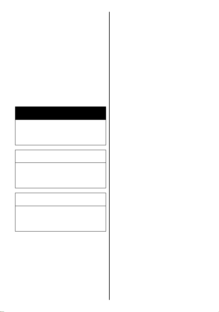
Please read this manual and follow its instructions carefully. To
emphasize special information,
the symbol
WAR NING, CAUTION,
and NOTE have special mean-
ings. Pay particular attention to
messages highlighted by these
signal words:
/NOTE
and the words
NOTICE
WARNING
Indicates a potential hazard
that could result in death or
serious injury.
CAUTION
Indicates a potential hazard
that could result in minor or
moderate injury.
NOTICE
Indicates a potential hazard
that could result in vehicle or
equipment damage.
Motorcycling is one of the most
exhilarating sports and to ensure
your riding enjoyment, you should
become thoroughly familiar with
the information presented in this
Owner’s Manual before riding the
motorcycle.
The proper care and maintenance
that your motorcycle requires is
outlined in this manual. By following these instructions explicitly,
you will ensure a long trouble-free
operating life for your motorcycle.
This motorcycle also conforms to
the U.S. Environmental Protection
Agency (EPA) and California Air
Resource Board (CARB) emission regulations which apply to
new motorcycles. The proper
adjustment of engine components
is necessary for this motorcycle to
comply with the EPA and CARB
regulations. Therefore, please follow the maintenance instructions
closely to ensure emission compliance. Your Suzuki dealer has
experienced technicians that are
trained to provide your machine
with the best possible service with
the right tools and equipment.
NOTE: Indicates special information to make maintenance easier
or instructions clearer.
Page 3
All information, illustrations and
specifications contained in this
manual are based on the latest
product information available at
the time of publication. Due to
improvements or other changes,
there may be some discrepancies between information in this
manual and your motorcycle.
Suzuki reserves the right to make
production changes at any time,
without notice and without incurring any obligation to make the
same or similar changes to vehicles previously built or sold.
Suzuki Motor Corporation
believes in conservation and protection of Earth’s natural
resources. To that end, we
encourage every vehicle owner to
recycle, trade in, or properly dispose of, as appropriate, used
motor oil, coolant, and other fluids, batteries and tires.
Page 4
TABLE OF CONTENTS
THE SPORT OF MOTORCYCLING
FUEL, ENGINE OIL AND COOLANT RECOMMENDATIONS
CONTROLS, EQUIPMENT AND ADJUSTMENTS
BREAK-IN AND INSPECTION BEFORE RIDING
RIDING TIPS
ACCESSORY USE AND MOTORCYCLE LOADING
INSPECTION AND MAINTENANCE
TROUBLESHOOTING
STORAGE PROCEDURE AND MOTORCYCLE CLEANING
1
2
3
4
5
6
7
8
9
CONSUMER INFORMATION
SPECIFICATIONS
INDEX
10
Page 5

Page 6

THE SPORT OF MOTORCYCLING
MOST ACCIDENTS CAN BE AVOIDED ............................................................. 1-2
IF YOU DON’T HAVE A HELMET, BUY A HELMET AND
WEAR IT EVERY TIME YOU RIDE ..................................................................... 1-2
IF A COLLISION IS IMMINENT, DO SOMETHING ............................................. 1-3
SPECIAL SITUATIONS REQUIRE SPECIAL CARE .......................................... 1-4
KNOW YOUR LIMITS .......................................................................................... 1-4
BE EXTRA SAFETY-CONSCIOUS ON BAD WEATHER DAYS ........................ 1-5
PRACTICE AWAY FROM TRAFFIC ................................................................... 1-5
INSPECTION BEFORE RIDING .......................................................................... 1-5
ACCESSORIES AND LOADING ......................................................................... 1-5
CARRYING A PASSENGER ............................................................................... 1-6
MOTORCYCLE SAFETY FOUNDATION’S
“RIDING TIPS AND PRACTICE GUIDE” HANDBOOK
(FOR OWNERS IN USA) .....................................................................................1-6
BE STREET SMART ........................................................................................... 1-6
LABELS ............................................................................................................... 1-6
CONCLUSION ..................................................................................................... 1-7
1
1-1
Page 7

THE SPORT OF
MOTORCYCLING
Your motorcycle and this owner’s
manual have been designed by
people like you who enjoy motorcycling. People become motorcyclists for many reasons. For
starters, street riding is fun and
invigorating. But no matter why
you became a motorcyclist, or
how experienced you are, you will
eventually face some challenging
situations.
In preparing for these challenges,
you will be fine-tuning your coordination, concentration, and attitude. Learning the skills and
strategies associated with motorcycling is the basis for safely participating in this sport. Many
motorcyclists find that as they
become better riders, they also
get more enjoyment from the freedom unique to motorcycling.
Please remember:
MOST ACCIDENTS CAN BE AVOIDE D
The most common type of motorcycle accident in the U.S. occurs
when a car traveling towards a
motorcycle turns left in front of the
motorcycle. Is that because other
drivers are out to get motorcyclists? No. Other drivers simply
don’t always notice motorcyclists.
Ride defensively. Wise motorcyclists use a strategy of assuming
they are invisible to other drivers,
even in broad daylight. Pay careful attention to other motorists,
especially at intersections,
because they may not be paying
attention to you. Select a lane
position that gives you the best
view of others, and other motorists the best view of you. Wear
bright, reflective clothing. Put
reflective strips on your helmet.
IF YOU DON’T HAVE A HELMET, BUY A HELMET AND WEAR IT EVERY TIME YOU RIDE
Most accidents occur within a few
miles of home, and almost half
occur at speeds of less than 30
mph. So even if you’re just going
on a quick errand, be prepared–
strap on your helmet before you
take off.
1-2
Page 8

Helmets do not reduce essential
vision or hearing. Generally, helmets do not cause or intensify
injury if you crash. Helmets simply
help your skull protect your intelligence, your memory, your personality, and your life.
Your eyesight is equally valuable.
Wearing suitable eye protection
can help keep your vision
unblurred by the wind and save
your eyes from airborne hazards
like bugs, dirt, or pebbles kicked
up by tires.
IF A COLLISION IS IMMINENT, DO SOMETHING
Many riders fear locking up their
brakes or haven’t learned to
swerve to avoid an accident.
Many inexperienced riders (and
too many seasoned riders) use
only their rear brake in an emergency, resulting in unnecessary
impacts in some cases and
unnecessarily high impact speeds
in other cases. Your rear brake
can only provide about 30% of
your motorcycle’s potential stopping power. The front and rear
brakes can and should be used
together to maximize braking
effectiveness.
Experienced motorcyclists learn
to “cover” the front brake lever by
lightly resting a couple of fingers
over the lever when riding in traffic
and near intersections to give
their reaction time a head start.
Emergency stopping and swerving are techniques that you
should practice and master before
you find yourself in an emergency
situation. The best place to practice such techniques is in a controlled environment such as the
Motorcycle Safety Foundation’s
(MSF) rider training courses. The
MSF’s Motorcycle Rider Courses
(fundamental techniques) and
Experienced Rider Courses
(advanced strategies) present
hands-on instruction of the basic
principles of motorcycling and a
variety of accident-avoidance
maneuvers. Even a seasoned
motorcyclist can improved his or
her riding skills, and pick up a few
new skills, through these courses.
Some insurance companies even
offer discounts to course graduates.
1-3
Page 9

SPECIAL SITUATIONS REQUIRE SPECIAL CARE
Of course, there are some times
when full-force braking is not the
correct technique. When the road
surface is wet, loose, or rough,
you should brake with care. When
you’re leaned over in a corner,
avoid braking. Straighten up
before braking. Better yet, slow
down before entering the corner.
In these situations, the traction
available between your tires and
the road surface is limited. Overbraking when traction is limited
will cause your tires to skid, possibly resulting in loss of directional
control or causing you and your
motorcycle to fall over.
KNOW YOUR LIMITS
Always ride within the boundaries
of your own skills. Knowing these
limits and staying within them will
help you avoid accidents.
A major cause of accidents involving only a motorcycle (and no
cars) is going too fast through a
turn. Before entering a turn, select
an appropriately low cornering
speed.
Even on straight roads, ride at a
speed that is appropriate for the
traffic, visibility and road conditions, your motorcycle, and your
experience.
Riding a motorcycle safely
requires that your mental and
physical skills are fully part of the
experience. You should not
attempt to operate a motor vehicle, especially one with two
wheels, if you are tired or under
the influence of alcohol or other
drugs. Alcohol, illegal drugs, and
even some prescription and overthe-counter drugs can cause
drowsiness, loss of coordination,
loss of balance, and especially
the loss of good judgment. If you
are tired or under the influence of
alcohol or other drugs, PLEASE
DO NOT RIDE your motorcycle.
1-4
Page 10

BE EXTRA SAFETY-CONSCIOUS ON BAD WEATHER DAYS
Riding on bad weather days,
especially wet ones, requires
extra caution. Braking distances
increase on a rainy day. Stay off
the painted surface marks, manhole covers, and greasy-appearing areas, as they can be
especially slippery. Use extra caution at railway crossings and on
metal gratings and bridges. When
it starts to rain, any oil or grease
on the road rises to the surface of
the water. Pull over and wait a few
minutes until this oil film is
washed away before riding.
Whenever in doubt about road
conditions, slow down!
PRACTICE AWAY FROM TRAFFIC
Your riding skill and your mechanical knowledge form the foundation for safe riding practices. We
suggest that you practice riding
your motorcycle in a non-traffic
situation until you are thoroughly
familiar with your machine and its
controls. Again, consider taking
one of the MSF’s Rider Courses.
Even experts will be pleased with
the caliber of the information presented in these courses. As the
MSF says: “The more you know,
the better it gets!”
INSPECTION BEFORE RIDING
Review the instructions in the
“INSPECTION BEFORE RIDING”
section of this manual. Perform an
entire pre-ride inspection before
you head out on the road. Spending a few minutes preparing your
machine for a ride can help prevent accidents due to mechanical
failure or costly, inconvenient
breakdowns far from home.
ACCESSORIES AND LOADING
The accessories you use with
your motorcycle and the manner
in which you load your gear onto
the bike might create hazards.
Aerodynamics, handling, balance,
and cornering clearance can suffer, and the suspension and tires
can be overloaded. Read the
“ACCESSORY USE AND
MOTORCYCLE LOADING” section.
1-5
Page 11

CARRYING A PASSENGER
Carrying a passenger, when done
correctly, is a great way to share
the joy of motorcycling. You will
have to alter your riding style
somewhat since the extra weight
of a passenger will affect handling
and braking. You may also need
to adjust tire pressures and suspension; please refer to the Tire
Pressure and Loading section
and the Suspension section for
more details.
MOTORCYCLE SAFETY FOUNDATION’S “RIDING TIPS AND PRACTICE GUIDE” HANDBOOK (FOR OWNERS IN USA)
This special handbook, supplied
with your owner’s manual, contains a variety of safety tips, helpful hints, and practice exercises.
This manual can increase your
riding enjoyment and safety. You
should read it thoroughly.
A passenger needs the same protection that you do, including a
helmet and proper clothing. The
passenger should not wear long
shoe laces or loose pants that
could get caught in the wheel or
the chain. Passengers must be
tall enough that their feet reach
the footrests.
BE STREET SMART
Always heed speed limits, local
laws, and the basic rules of the
road. Set a good example for others by demonstrating a courteous
attitude and a responsible riding
style.
LABELS
Read and follow all the labels on
the motorcycle. Make sure you
understand all of the labels. Do
not remove any labels from the
motorcycle.
1-6
Page 12
CONCLUSION
Traffic, road and weather conditions vary. Other motorists’
actions are unpredictable. Your
motorcycle’s condition can
change. These factors can best
be dealt with by giving every ride
your full attention.
Circumstances beyond your control could lead to an accident. You
need to prepare for the unexpected by wearing a helmet and
other protective gear, and learning emergency braking and
swerving techniques to minimize
the damage to you and your
machine.
The best way to learn basic riding
skills and evasive maneuvers or
refresh your own riding skills is to
take one of the courses offered by
the Motorcycle Safety Foundation.
Your Suzuki dealer can help you
locate the fundamental or
advanced riding skills course
nearest you, or owners in the USA
can call toll-free 1-800-446-9227.
Good riding on your new Suzuki!
1-7
Page 13
Page 14

FUEL, ENGINE OIL AND COOLANT
RECOMMENDATIONS
FUEL .................................................................................................................... 2-2
ENGINE OIL ......................................................................................................... 2-4
ENGINE COOLANT SOLUTION ......................................................................... 2-6
2
2-1
Page 15
FUEL, ENGINE OIL AND
COOLANT
RECOMMENDATIONS
FUEL
Your motorcycle requires premium unleaded gasoline with a
minimum pump octane rating of
90 ((R+M)/2 method). In some
areas, the only fuels that are
available are oxygenated fuels.
Oxygenated fuels which meet the
minimum octane requirement and
the requirements described below
may be used in your motorcycle
without jeopardizing the New
Vehicle Limited Warranty or the
Emission Control System Warranty.
NOTE: Oxygenated fuels are
fuels which contain oxygen-carrying additives such as alcohol.
NOTE:
• The GSX-R600 engine is
designed to use premium
unleaded gasoline only. Use
premium unleaded gasoline
under all riding conditions.
• If the engine develops some
trouble like lack of acceleration
or insufficient power, the cause
may be due to the fuel the
motorcycle uses. In such case,
try changing to a different gas
station. If the situation is not
improved by changing, consult
your Suzuki dealer.
Gasoline/Ethanol Blends
Blends of unleaded gasoline and
ethanol (grain alcohol), also
known as GASOHOL, are commercially available in some areas.
Blends of this type may be used in
your motorcycle if they are no
more than 10% ethanol. Make
sure this gasoline-ethanol blend
has octane ratings no lower than
those recommended for gasoline.
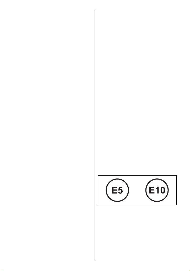
Use the recommended gasoline
which conforms to the following
labels.
or
2-2
Page 16

Fuel Pump Labeling
In some states, pumps that dispense oxygenated fuels are
required to be labeled for the type
and percentage of oxygenate, and
whether important additives are
present. Such labels may provide
enough information for you to
determine if a particular blend of
fuel meets the requirements listed
above. In other states, pumps
may not be clearly labeled as to
the content or type of oxygenate
and additives. If you are not sure
that the fuel you intend to use
meets these requirements, check
with the service station operator
or the fuel supplier.
NOTE:
• To help minimize air pollution,
Suzuki recommends that you
use oxygenated fuels.
• Be sure that any oxygenated
fuel you use has octane ratings of at least 90 pump
octane ((R+M)/2 method).
• If you are not satisfied with the
drivability of your motorcycle
when you are using an oxygenated fuel, or if engine pinging is experienced, substitute
another brand as there are differences between brands.
NOTICE
Spilled gasoline containing
alcohol can damage the
painted surfaces of your
motorcycle.
Be careful not to spill any fuel
when filling the fuel tank. Wipe
spilled gasoline up immediately.
2-3
Page 17
ENGINE OIL
Suzuki recommends the use of
SUZUKI PERFORMANCE 4
MOTOR OIL or equivalent engine
oil. If SUZUKI PERFORMANCE 4
MOTOR OIL is not available,
select a proper engine oil according to the following guideline.
Oil quality is a major contributor to
your engine’s performance and
life. Always select good quality
engine oil. Use oil with an API
(American Petroleum Institute)
classification of SG, SH, SJ, SL,
SM or SN with a JASO classification of MA.
SAE API JASO
10W-40
API: American Petroleum Institute
JASO: Japanese Automobile
Standards Organization
NOTE: SUZUKI highly recommends the use of ECSTAR brand
engine oil. ECSTAR has been
specially formulated for your
SUZUKI product and contributes
to the desired motorcycle performance and ideal riding experience.
SG, SH, SJ, SL,
SM or SN
MA
SAE Engine Oil Viscosity
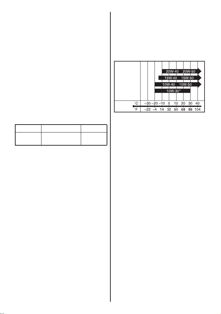
Suzuki recommends the use of
SAE 10W-40 engine oil. If SAE
10W-40 engine oil is not available,
select an alternative according to
the following chart.
ENGINE OIL
TEMP.
* USE ONLY SG, SH, SJ or SL.
2-4
Page 18
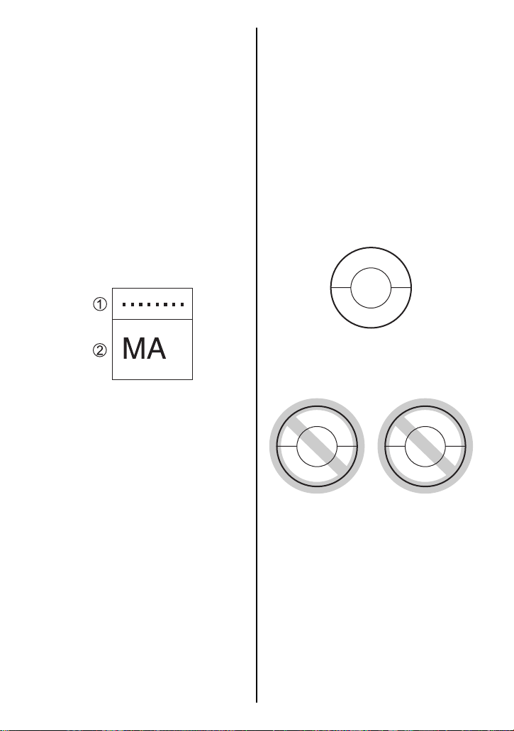
JASO T903
The JASO T903 standard is an
index to select engine oils for 4stroke motorcycle and ATV
engines. Motorcycle and ATV
engines lubricate clutch and
transmission gears with engine
oil. JASO T903 specifies performance requirements for motorcycle and ATV clutches and
transmissions.
There are two classes, MA and
MB. The oil container shows the
classification as follows.
Energy Conserving
Suzuki does not recommend the
use of “ENERGY CONSERVING”
or “RESOURCE CONSERVING”
oils. Some engine oils which have
an API classification of SH, SJ,
SL, SM or SN have an “ENERGY
CONSERVING” or “RESOURCE
CONSERVING” indication in the
API classification donut mark.
These oils can affect engine life
and clutch performance.
API SG, SH, SJ, SL, SM or SN
V
R
I
C
E
E
S
I
S
P
A
Recommended
J
SAE
10W-40
1
Code number of oil sales company
2
Oil classification
API SH, SJ, SL or SM
V
R
E
S
I
P
A
SAE
E
N
10W-40
E
R
G
Y
C
O
2-5
I
C
E
S
J
R
G
N
I
V
R
E
S
N
E
S
O
Not recommended
API SN
R
E
S
I
P
A
SAE
10W-40
U
R
C
E
C
V
I
C
E
S
N
G
N
I
V
R
E
S
N
O
Page 19

ENGINE COOLANT SOLUTION
Use “SUZUKI SUPER LONG
LIFE COOLANT” or “SUZUKI
LONG LIFE COOLANT”. If
“SUZUKI SUPER LONG LIFE
COOLANT” and “SUZUKI LONG
LIFE COOLANT” are not available, use a glycol-based antifreeze compatible with an
aluminum radiator mixed with distilled water only at the ratio of
50:50.
WARNING
Engine coolant is harmful or
fatal if swallowed or inhaled.
Solution can be poisonous to
animals.
NOTICE
Spilled engine coolant can
damage the painted surfaces of
your motorcycle.
Be careful not to spill any fluid
when filling the radiator. Wipe
spilled engine coolant up
immediately.
NOTE: SUZUKI highly recommends the use of ECSTAR brand
coolant. ECSTAR has been specially formulated for your SUZUKI
product and contributes to the
desired motorcycle performance
and ideal riding experience.
Do not drink antifreeze or coolant solution. If swallowed, do
not induce vomiting. Immediately contact a poison control
center or a physician. Avoid
inhaling mist or hot vapors; if
inhaled, remove to fresh air. If
coolant gets in eyes, flush eyes
with water and seek medical
attention. Wash thoroughly
after handling. Keep out of the
reach of children and animals.
ENGINE COOLANT
Engine coolant performs as a rust
inhibitor and water pump lubricant
as well as an anti-freeze solution.
Therefore engine coolant should
be used at all times even though
the atmospheric temperature in
your area does not go down to the
freezing point.
2-6
Page 20
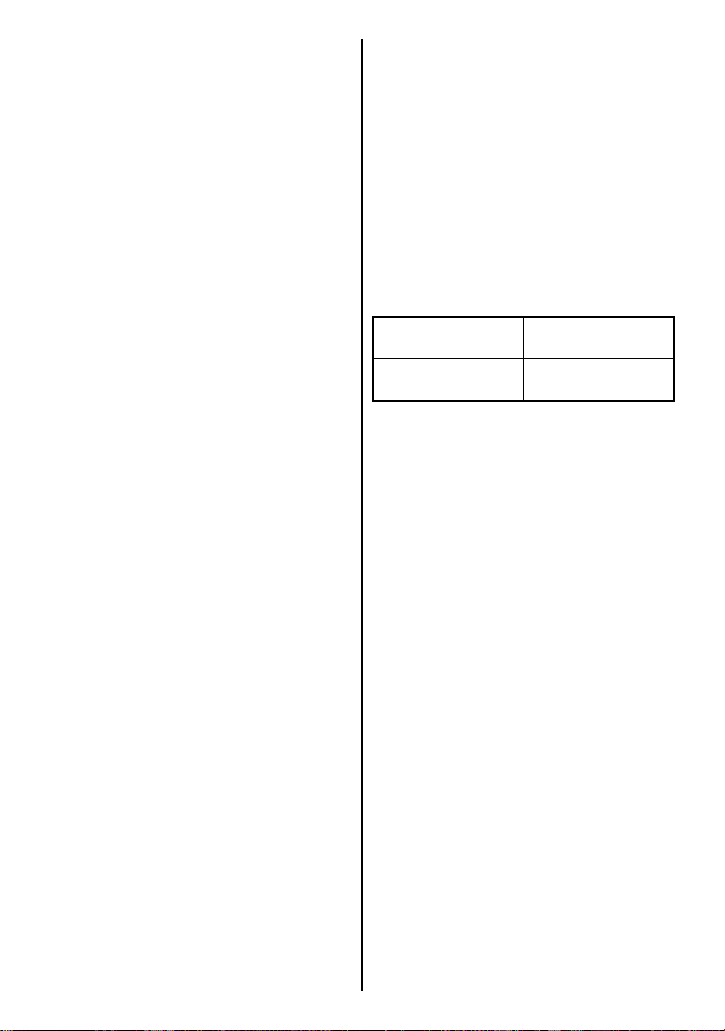
SUZUKI SUPER LONG LIFE
COOLANT (Blue)
“SUZUKI SUPER LONG LIFE
COOLANT” is pre-mixed to the
proper ratio. Add only “SUZUKI
SUPER LONG LIFE COOLANT”
if coolant level drops. It is not necessary to dilute “SUZUKI SUPER
LONG LIFE COOLANT” when
replacing coolant.
SUZUKI LONG LIFE COOLANT
(Green)
Water for Mixing
Use distilled water only. Water
other than distilled water can corrode and clog the aluminum radiator.
Required amount of engine coolant/water solution capacity (total):
2700 ml (2.9 US qt)
Engine coolant
Wate r
1350 ml
(1.4 US qt)
1350 ml
(1.4 US qt)
NOTE: This 50% mixture will
protect the cooling system from
freezing at temperatures above
–31°C (–24°F). If the motorcycle
is to be exposed to temperature
below –31°C (–24°F), this mixing ratio should be increased up
to 55% (–40°C/–40°F) or 60%
(–55°C/–67°F) coolant. The mixing ratio should not exceed 60%
coolant.
2-7
Page 21
Page 22

CONTROLS, EQUIPMENT AND
ADJUSTMENTS
LOCATION OF PARTS ....................................................................................... 3-2
KEY ...................................................................................................................... 3-5
IGNITION SWITCH .............................................................................................. 3-5
INSTRUMENT PANEL ......................................................................................... 3-8
LEFT HANDLEBAR ........................................................................................... 3-22
RIGHT HANDLEBAR ........................................................................................3-25
FUEL TANK CAP .............................................................................................. 3-28
GEARSHIFT LEVER .......................................................................................... 3-29
REAR BRAKE PEDAL ...................................................................................... 3-30
SEAT LOCK AND HELMET HOLDERS ........................................................... 3-30
SIDE STAND ...................................................................................................... 3-32
SUSPENSION ADJUSTMENT ..........................................................................3-33
FOOTRESTS AND GEARSHIFT LEVER POSITION CHANGE .......................3-38
3
3-1
Page 23
CONTROLS, EQUIPMENT AND ADJUSTMENTS
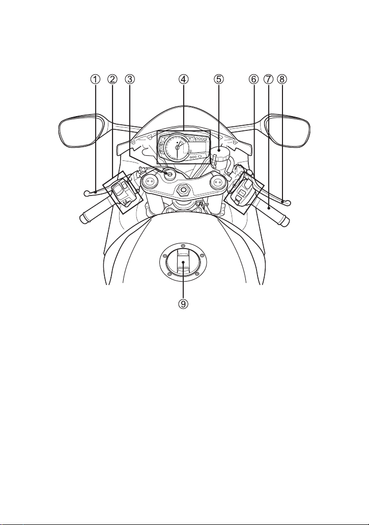
LOCATION OF PARTS
1 Clutch lever
2 Left handlebar switches
3 Ignition switch
4 Instrument panel
5 Front brake fluid reservoir
6 Right handlebar switches
7 Throttle grip
8 Front brake lever
9 Fuel tank cap
3-2
Page 24
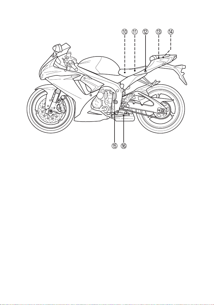
0 Battery
A Fuses
B Seat lock
C Helmet holders
D To o ls
E Gearshift lever
F Side stand
3-3
Page 25
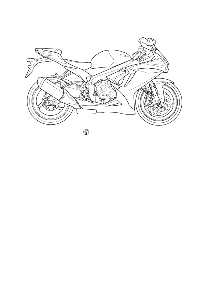
G Rear brake pedal
3-4
Page 26
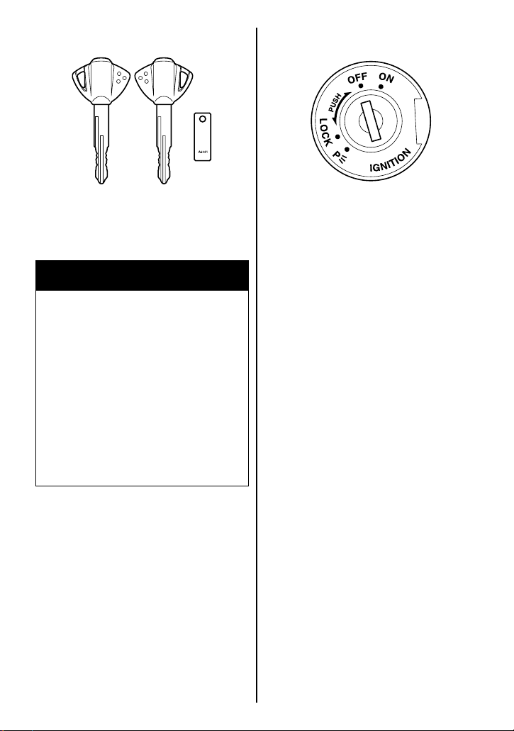
KEY
IGNITION SWITCH
Two keys come with this motorcycle. Keep the spare key in a safe
place.
WARNING
Due to the location of the steering damper, some key chains
could get caught between the
steering damper and the steering stem nut. This could interfere with steering and cause
loss of control.
Use your ignition key without
key chains, fobs or other keys
attached.
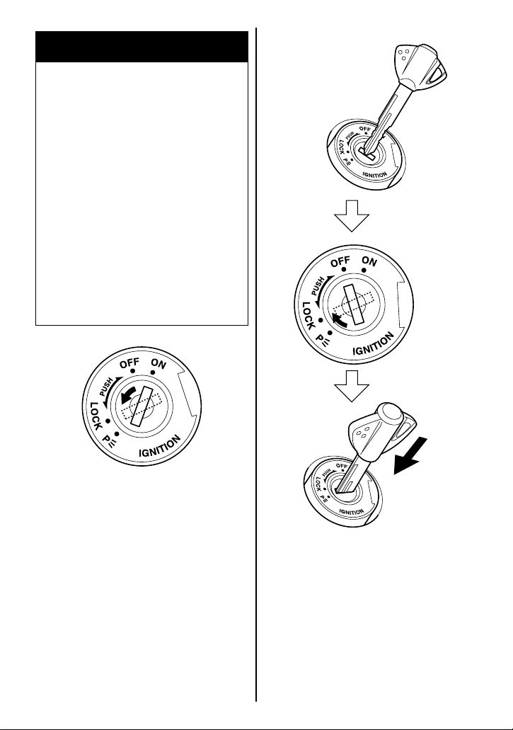
The ignition switch has 4 positions:
“OFF” position
All electrical circuits are cut off.
The engine will not start. The key
can be removed.
“ON” position
The ignition circuit is completed
and the engine can run. The
headlight and taillight will automatically turn on. The key cannot
be removed in this position.
NOTE: Start the engine promptly
after turning the key to the “ON”
position, or the battery will lose
power due to consumption by the
headlight and taillight.
3-5
Page 27
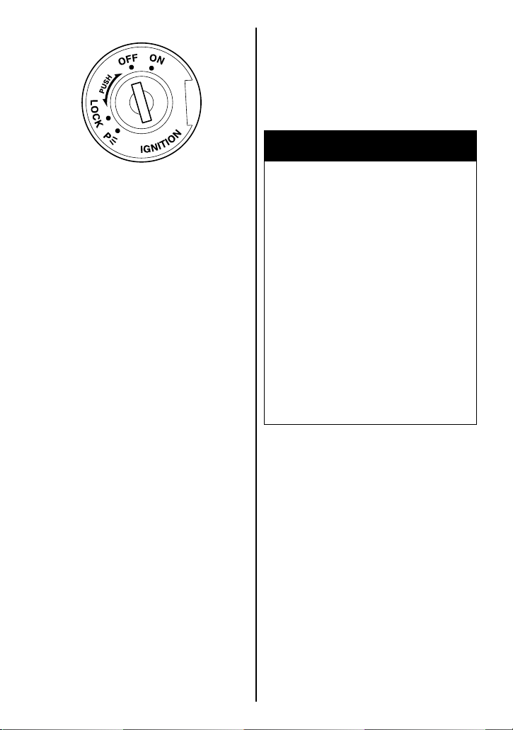
“LOCK” position
All electrical circuits are off. The
key can be removed and the
steering will be locked. Turn the
steering all the way to the left and
push down the key and turn it to
the “LOCK” position.
“P” (PARKING) position
Taillight will come on to increase
visibility for temporary roadside
parking at night. The key can be
removed and the steering will be
locked.
WARNING
Turning the ignition switch to
the “P” (PARKING) or “LOCK”
position while the motorcycle
is moving can be hazardous.
Moving the motorcycle while
the steering is locked can be
hazardous. You could lose your
balance and fall, or you could
drop the motorcycle.
Stop the motorcycle and place
it on the side stand before locking the steering. Never attempt
to move the motorcycle when
the steering is locked.
3-6
Page 28
WARNING
If the motorcycle falls down
due to a slip or collision, unexpected damage to the motorcycle could cause the engine to
keep running, which could
result in a fire, or could result
in injury from moving parts
such as the rear wheel.
If the motorcycle falls down,
turn the ignition switch off
immediately. Ask your authorized Suzuki dealer to inspect
the motorcycle for unseen
damage.
The key hole can be covered by
turning the lid.
Align the lid hole position with the
key hole position when inserting
the key.
3-7
Page 29
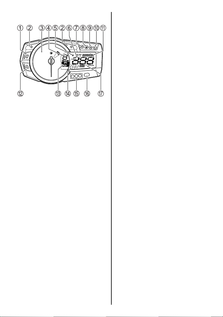
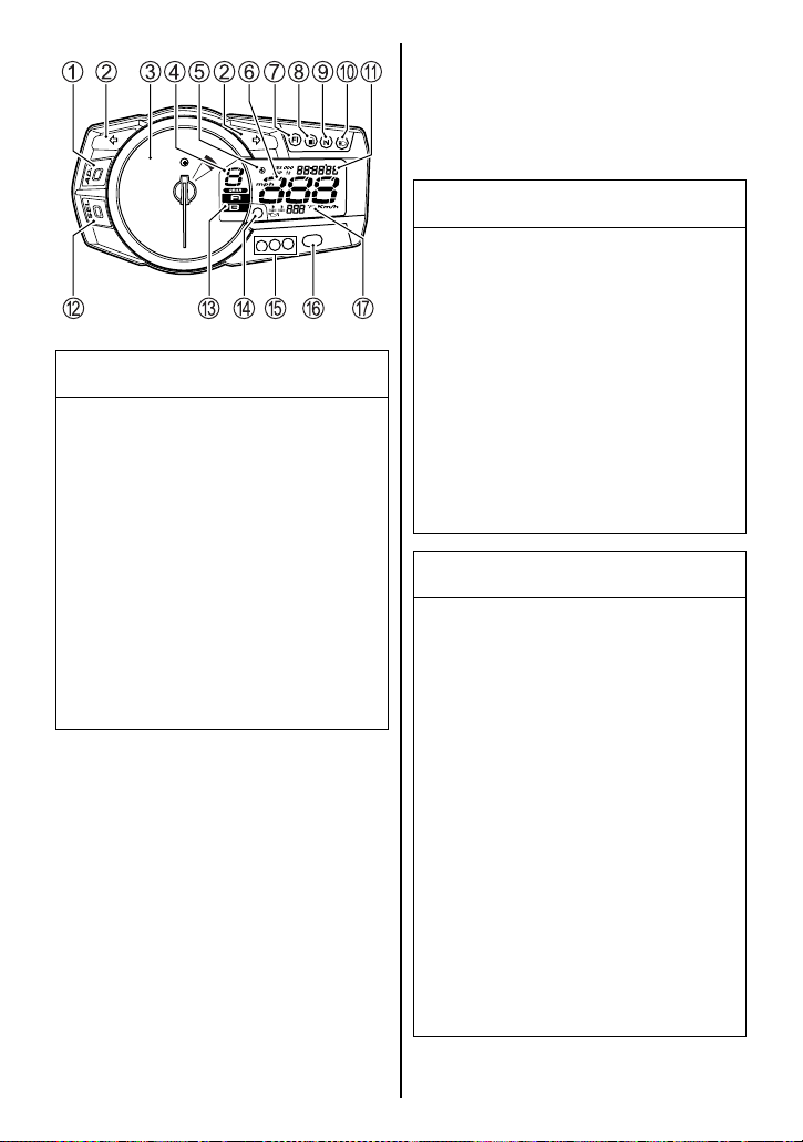
INSTRUMENT PANEL
The electronic control system
indicator light 7
light 8
, engine coolant tempera-
ture indicator light/oil pressure
indicator light D
cator lights E
tachometer needle work as follows to confirm their function
when the ignition switch is turned
to the “ON” position.
• The electronic control system
indicator light 7, fuel indicator
light 8
, engine coolant tem-
perature indicator light/oil
pressure indicator light D and
engine rpm indicator lights E,
F come on for 3 seconds.
• The tachometer needle moves
to the full scale position and
returns to the home position.
• All LCD segments appear and
then show the normal display.
, fuel indicator
, engine rpm indi-
, F, LCD’s and
If the tachometer needle does not
point to zero, follow the procedure
below to reset the tachometer.
1. Press and hold the ADJ button
1 and turn on the ignition
switch.
2. Hold the ADJ button 1 for 3 –
5 seconds.
3. Release the ADJ button 1.
Rap the ADJ button twice.
NOTE: The reset procedure, from
step 1 to step 3, should be performed within 10 seconds.
Turn Signal Indicator Light
“” 2
When the turn signals are being
operated either to the right or to
the left, the indicator light will blink
intermittently.
NOTE: If a turn signal light is not
operating properly due to bulb filament or circuit failure, the indicator light blinks more quickly to
notify the rider of the existence of
a problem.
3-8
Page 30

Tachometer 3
The tachometer indicates the
engine speed in revolutions per
minute (r/min).
Speedometer 6
The speedometer indicates the
road speed in miles per hour or
kilometers per hour.
Gear Position Indicator 4
The gear position indicator indicates gear position. This indicator displays “0” when the
transmission is in neutral.
NOTE: When the display indicates “CHEC” in the odometer
display area, the gear position
indicator does not indicate a number but indicates “–”.
NOTE:
• Set the meter display A to
odometer, then press and hold
buttons, ADJ 1 and SEL B,
for 3 seconds to switch
between mph and km/h. At the
same time, the odometer will
be changed between mile and
km.
• Select mph or, km/h as appropriate, to comply with traffic
regulations.
• Check mph and km/h display
after adjusting the instrument
panel display.
3-9
Page 31
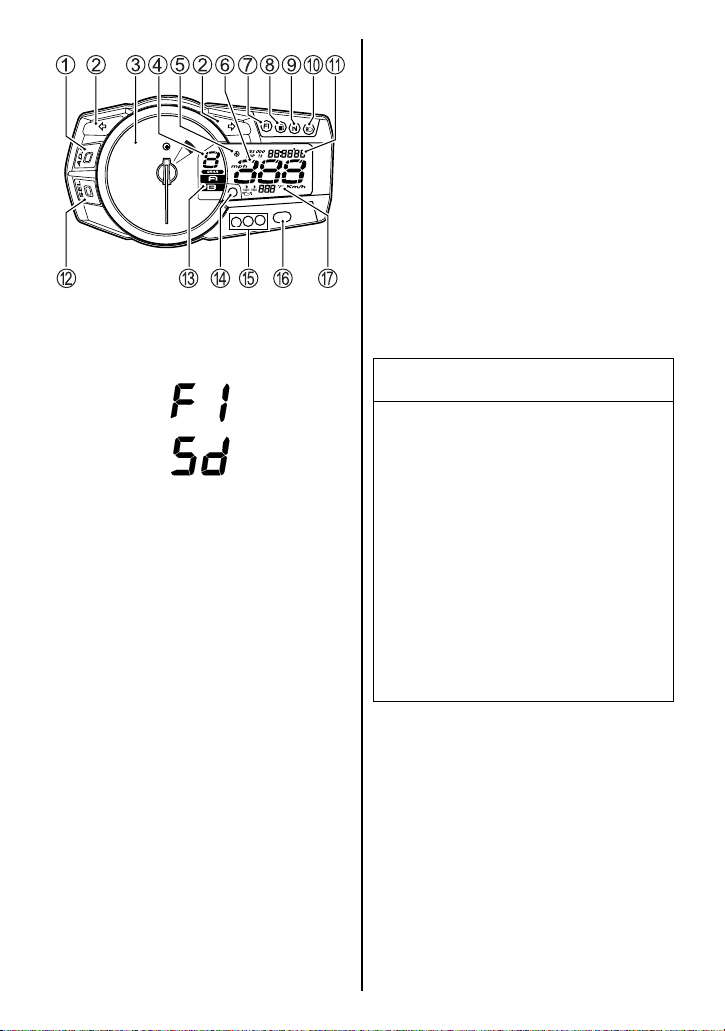
Electronic Control Indicator
Light 7
If the electronic control system
fails, the red indicator light 7
comes on and the display indicates “FI” or “Sd” in the odometer
display area in following 2 modes;
A. The display A in the odometer
display area alternately indicates “FI” or “Sd” and the displayed mode reading, and the
red indicator light 7 comes on
and remains lit. The engine
may continue to run in this
mode. The display A indicates
“FI”, “Sd” and the displayed
mode repeatedly when both
fuel injection system and
steering damper system failed.
B. The display A in the odometer
display indicates “FI” or “Sd”
continuously and the red indicator light 7 blinks. The
engine will not run in this
mode.
NOTE: The indicator displays “FI”
when the fuel injection system
has malfunction. The indicator
displays “Sd” when the steering
damper solenoid, battery voltage
and speed sensor have malfunction.
NOTICE
The electronic control indicator
light comes on to indicate a
problem with the electronic
control system.
If the display indicates “FI” or
“Sd” and the red indicator light
comes on, have your authorized Suzuki dealer or a qualified mechanic inspect the
electronic control system as
soon as possible.
NOTE: If the display indicates “FI”
or “Sd” continuously and the red
indicator light blinks, the engine
will not start.
3-10
Page 32

When the display indicates
“CHEC” in the odometer display
area check the following items;
• Make sure that the engine stop
switch is in the “” position.
• Make sure that the transmission is in neutral or the side
stand is fully up.
If the display still indicates
“CHEC” after checking the above
items, inspect the ignition fuse
and the connection of the lead
wire couplers.
Fuel Indicator Light “” 8
This indicator light comes on for 3
seconds when the ignition switch
is turned to the “ON” position.
Then the indicator light should go
out if there is enough fuel in the
tank. When the fuel in the fuel
tank drops below approximately
3.9 L (1.0 US gal), this indicator
blinks. When the fuel in the fuel
tank drops below approximately
1.5 L (0.4 US gal), this indicator
light comes on and remains on.
NOTE: When the fuel indicator
light comes on, you should add
fuel to the fuel tank at the first
opportunity to avoid running out of
fuel.
Neutral Indicator Light “N” 9
The green indicator light will come
on when the transmission is in
neutral. The light will go out when
you shift into any gear other than
neutral.
High Beam Indicator Light “”
0
This blue indicator light will be lit
when the headlight high beam is
turned on.
3-11
Page 33
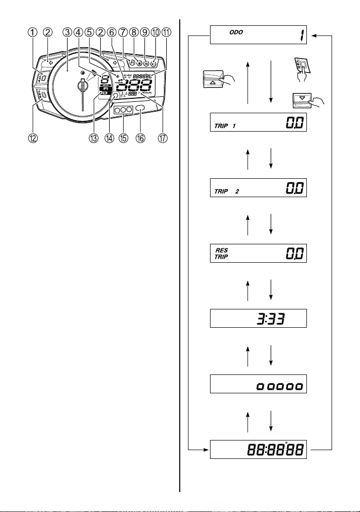
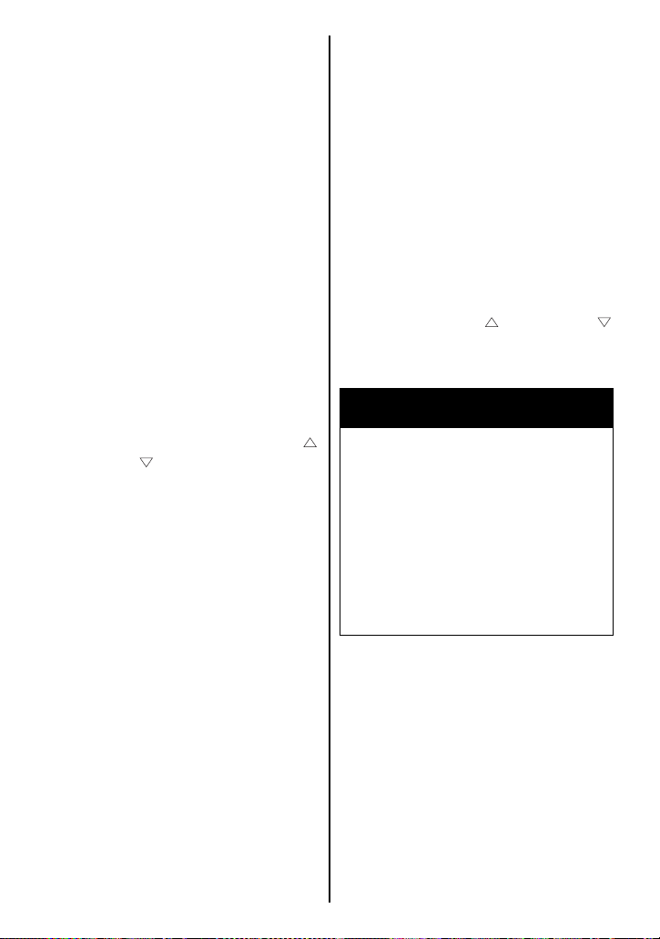
Odometer/Trip Meter/
Reserve Trip Meter/Clock/
Instrument Panel Light
Brightness/
Lap Time Counter A
The display has 7 functions;
odometer, 2 trip meters, reserve
trip meter, clock, instrument panel
light brightness and lap time
counter. When the ignition switch
is turned to the “ON” position, the
test pattern is displayed. The display is memorized when the ignition switch is turned off and the
memorized display appears when
the ignition switch is turned on
again.
Odometer
METERMETER
Trip meter 1
Trip meter 2
Reserve trip meter
Clock
To change the display, push the
SEL button B or right handlebar
switch of lap time counter switch.
The display changes in the order
below.
Instrument panel light brightness
Lap time counter
3-12
Page 34
Odometer
The odometer registers the total
distance that the motorcycle has
been ridden. The odometer
ranges from 0 to 999999.
NOTE: The odometer display
locks at 999999 when the total
distance exceeds 999999.
Trip meter
The 2 trip meters are resettable
odometers. They can register 2
kinds of distances at the same
time. For instance, trip meter 1
can register the trip distance and
trip meter 2 can register the distance between fuel stops.
To reset a trip meter to zero, push
the ADJ button 1 or METER
or METER for 2 seconds while
the display indicates the trip
meter, 1 or 2, you want to reset.
NOTE: When the trip meter
exceeds 9999.9, the trip meter will
return to 0.0 and start counting
again.
NOTE: The trip meter will be reset
to zero when the battery is
removed or battery is discharged.
Reserve trip meter
The reserve trip meter counts distance from fuel tank reserve point
until the fuel tank is refilled. The
fuel level indicator starts blinking
and the reserve trip meter starts
counting when the fuel level
reaches the reserve point. The
trip meter will be reset to zero
automatically when the fuel tank
is refilled over halfway and the
motorcycle starts moving. The
reserve trip meter can be reset
manually by pushing the ADJ button 1 or METER or METER
for more than 5 seconds with fuel
tank filled over halfway.
WARNING
Changing the display while
riding can be hazardous.
Removing a hand from the handlebars can reduce your ability
to control the motorcycle.
Never change the display while
riding. Keep both hands on the
handlebars.
3-13
Page 35
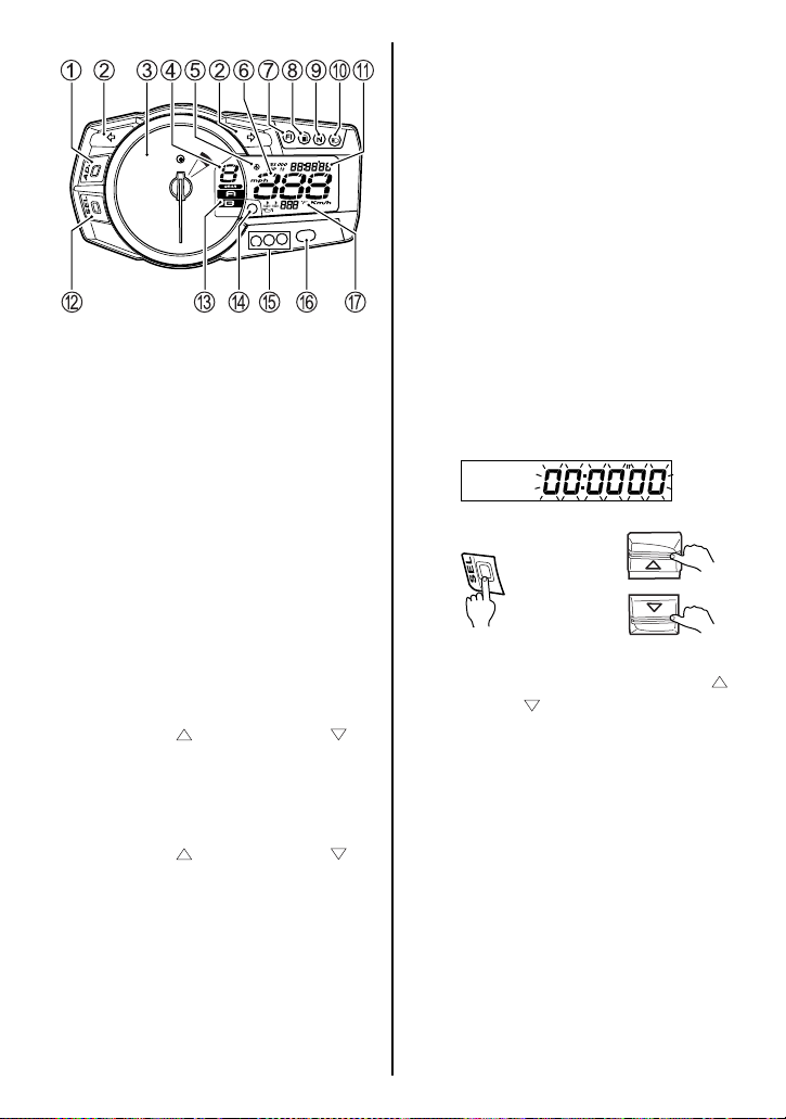
Clock
The clock has a 12-hour display.
Follow the procedure below to
adjust the clock.
1. Press and hold the SEL button
B for 3 seconds until the hour
display blinks.
2. Adjust the hour display by
pushing the ADJ button 1.
NOTE: When the ADJ button 1 is
held in, the display advances continuously.
3. Push the SEL button B or
METER or METER to
highlight the minute display.
4. Adjust the minute display by
pushing the ADJ button 1.
5. Push the SEL button B or
METER or METER to
return to the clock mode.
Instrument panel light
brightness
Pushing the ADJ button 1 will
change the instrument panel light
brightness in 5 steps. The brightness indicator indicates brightness from “
” (max).
“
” (min) to
Lap time counter
The lap time counter can counts
99 lap times and total time. The
lap time counter indicates from
00:00”00 to 99:59”99.
1. To use lap time counter
METER
Push SEL button B, METER
or METER to select lap time
counter. The display blinks
00:00”00 or memory data when
the lap time counter is selected.
The lap time counter cannot be
operated when the display is
blinking.
3-14
Page 36
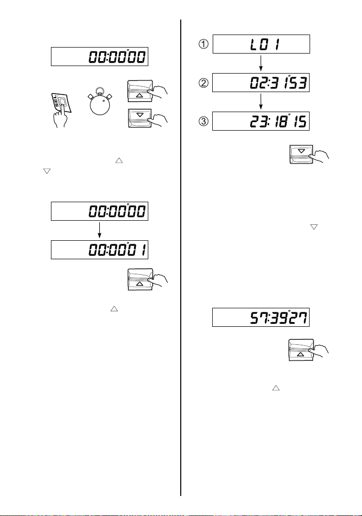
2. To measure lap time
1
METER
1.Press and hold the SEL but-
ton B, METER or METER
for more than 1 second.
The display stops blinking.
METER
2.Push METER to start lap
time counter.
METER
1 Lap number
2 Lap time
3 Tot a l ti me
3.When the METER is
pushed, the lap time counter
records lap time data and the
display shows lap number and
then shows lap time for 4 seconds.
METER
4.Push METER to stop lap
time counter.
3-15
Page 37
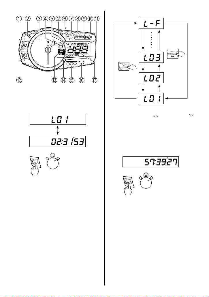
3. To check lap time memory
data
3
METER
METER
2.Push METER or METER
to increase or decrease lap
number.
3.L – F indicates minimum lap
time.
1.Press and hold the SEL but-
ton B for more than 3 seconds. Display shows lap
number and lap time alternately.
3
4.Press and hold the SEL button B for more than 3 seconds. The lap time counter
returns to lap time measure
mode.
3-16
Page 38
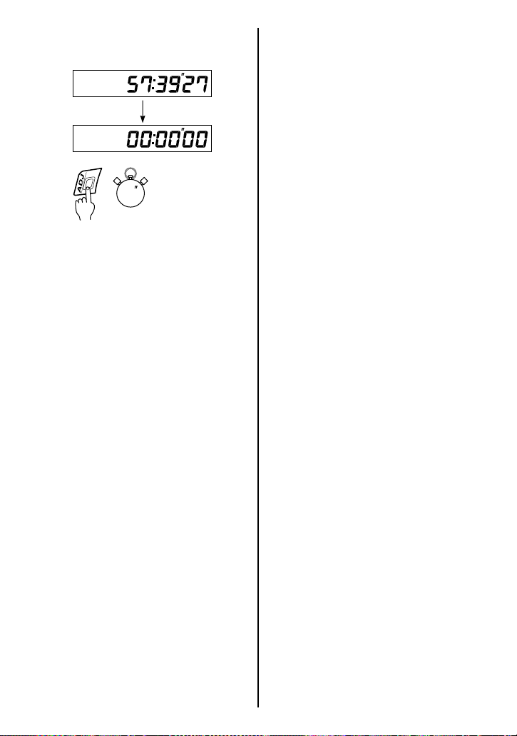
4. To clear lap time memory data
3
1.Press and hold ADJ button 1
for more than 3 seconds to
clear the lap time memory
data.
2.The lap time counter shows
00:00”00.
Suzuki Drive Mode Indicator C
The Suzuki drive mode indicator
displays drive mode, A and B,
when the Suzuki drive mode
selector is activated. Refer to the
LEFT HANDLEBAR section for
detail.
NOTE: Letter “C” may come to be
seen under the direct sunshine.
However, this motorcycle has two
modes, A and B.
Engine Coolant Temperature
Indicator Light/Oil Pressure
Indicator Light D
The display G and the indicator
light D have 2 functions, engine
coolant temperature indicator and
oil pressure indicator. The display
G normally indicates coolant temperature. The oil pressure symbol
“” activates when the oil pressure is low.
Engine Coolant Temperature
Indicator
When the ignition switch is turned
to the “ON” position, the display
shows the test pattern for 3 seconds. Then the display changes
to the engine coolant temperature
indicator. While the coolant temperature is below 67°F, the display
does not indicate a number but
indicates “– – –”.
When the coolant temperature is
higher than 248°F, the display
temperature, symbol “” blinks
and the indicator light D comes
on. Further, if the temperature
exceeds 283°F, the display shows
“HI”, symbol “” blinks and the
indicator light D remains on.
When the engine coolant temperature indicator light comes on,
stop the engine and check the
coolant level after the engine
cools.
3-17
Page 39
NOTICE
Riding the motorcycle with the
engine coolant temperature
indicator light lit can cause
serious engine damage due to
overheating.
When the engine oil pressure
drops under the normal operating
range, the symbol “” in the
display appears and the indicator
light D comes on.
NOTICE
After starting the engine, opening the throttle or running the
motorcycle with the oil pressure indicator light turned on
may adversely affect the
engine.
Make sure that the oil pressure
indicator light has turned off
before operating the throttle or
running the motorcycle.
If the engine coolant temperature indicator light comes on,
stop the engine to let it cool.
Do not run the engine until the
engine coolant temperature
indicator light goes off.
Oil Pressure Indicator
When the ignition switch is in the
“ON” position but the engine has
not been started, the symbol
“” in the display and the indicator light D comes on. As soon
as the engine is started, the symbol “” and the indicator light
should go out.
NOTICE
Riding the motorcycle with the
oil pressure indicator light lit
can damage the engine and
transmission.
If the oil pressure indicator
light comes on, indicating low
oil pressure, stop the engine
immediately. Check the oil level
and add oil if necessary. If
there is a proper amount of oil
and the light still does not go
out, have your authorized
Suzuki dealer or a qualified
mechanic inspect your motorcycle.
3-18
Page 40
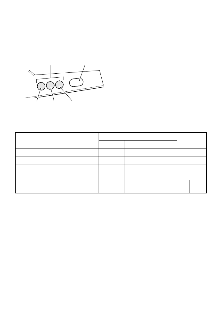
Engine Rpm Indicator E, F
The engine rpm indicator LED’s will light or blink when the engine
speed reaches a preset engine rpm.
NOTE: Be sure to reset the engine rpm indicator in the instrument
panel when the battery terminals are reconnected.
Orange LED White LED
LED1 LED2 LED3
When the white LED is set at 10000 r/min and orange LED range is set
at 500 r/min.
Engine rpm and preset rpm (r/min)
Engine rpm < 8500 – – – –
8500 Engine rpm < 9000 –– –
9000 Engine rpm < 9500 ––
9500 Engine rpm < 10000 –
10000 Engine rpm
Orange LED E
LED1 LED2 LED3
White LED F
The LED setting will be changed as follows:
1. White LED Lighting
set RPM Setting
→ 2. White LED Brightness → 3. White LED Pre-
→ 4. Orange LED Preset RPM Range Setting
3-19
Blink
Page 41
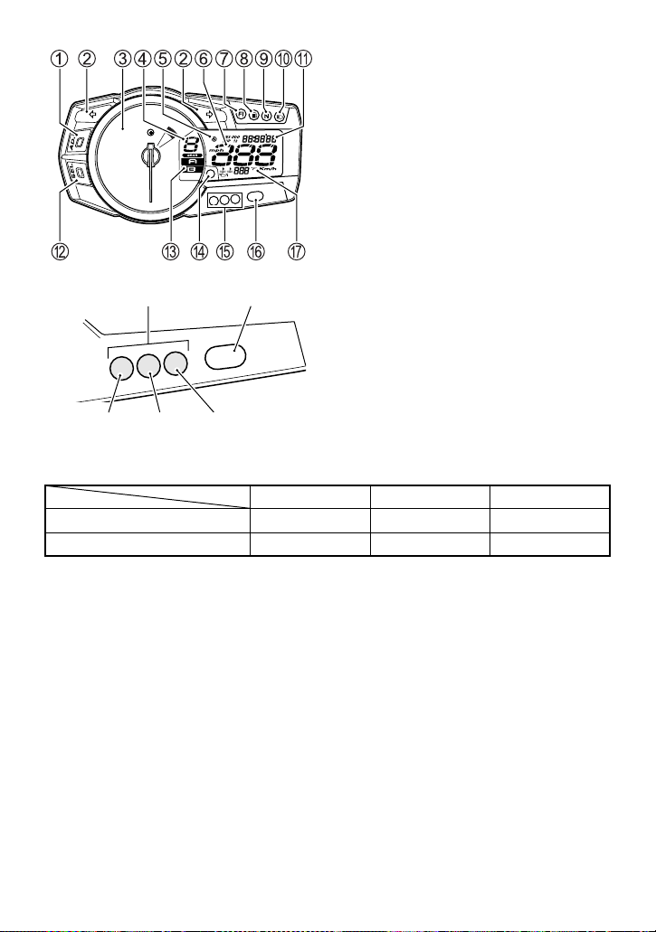
Orange LED White LED
LED1 LED2 LED3
1. White LED Lighting
LIGHT BLINK NO LIGHT
White LED Blink –
Indicator mark
–
1.Press and hold the SEL button B and turn on the ignition switch.
Keep the SEL button B pressed for more than 2 seconds.
2.Push the ADJ button 1 to change the lighting mode. The mode
changes as follows: LIGHT
→ BLINK → NO LIGHT → LIGHT. The
white LED comes on in the LIGHT mode and blinks in the BLINK
mode. The engine rpm indicator mark “” comes on when the
mode is in LIGHT or BLINK mode is selected. When the SEL button B is pushed in the NO LIGHT mode, the selection mode will be
canceled and it will return the normal display mode.
3-20
Page 42
2. White LED Brightness
1.Push the SEL button B from white LED lighting mode to change
white LED brightness mode.
2.Push the ADJ button 1 to change brightness in 5 steps. The
brightness indicator changes from “
” (min) to “”
(max).
3. White LED Preset RPM Setting
1.Push the SEL button B from the white LED brightness mode to
change white LED preset rpm setting. The white LED will light preset setting and tachometer indicates preset rpm.
2.Push the ADJ button 1 to change the preset rpm from 7000 r/min
to 10000 r/min in step 250 r/min and from 10000 r/min to 15250 r/
min in step 50 r/min. When the ADJ button 1 is held in, the preset
rpm will advance continuously.
4. Orange LED Preset RPM Range Setting
1.Push the SEL button B from the white LED preset rpm setting
mode to change orange LED preset rpm range setting.
2.Push the ADJ button 1 to change orange LED preset rpm range
as follows: 250 r/min
→ 500 r/min → 1000 r/min → 250 r/min
When the White LED is preset at 10000 r/min.
Orange LED preset rpm range A
250 9250 9500 9750 10000
500 8500 9000 9500 10000
1000 7000 8000 9000 10000
Orange LED E
LED1 LED2 LED3
White
LED F
3.Push the SEL button B to return from adjustment mode to normal
display mode.
The engine rpm indicator system holds the selected setting when the
ignition switch is turned off. The system settings will remain when the
ignition switch is turned on again.
3-21
Page 43
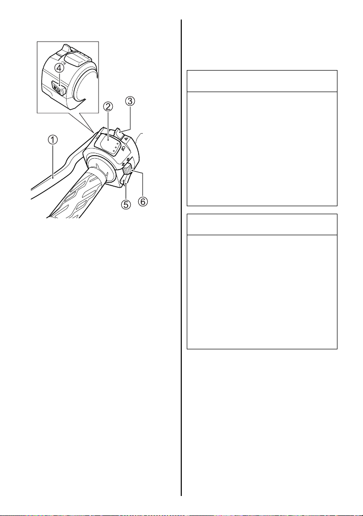
LEFT HANDLEBAR
Headlight flasher switch
Press the dimmer switch of “”
position to flash the headlight high
beam.
NOTICE
Sticking tape or placing
objects in front of the headlight
can obstruct headlight heat
radiation. This can result in
headlight damage.
Do not stick tape on the headlight or place objects in front of
the headlight.
Clutch Lever 1
The clutch lever is used for disengaging the drive to the rear wheel
when starting the engine or shifting transmission gears. Squeezing the lever disengages the
clutch.
Dimmer Switch 2
“” position
The headlight low beam turns on.
“” position
The headlight high beam and
headlight low beam turn on. The
high beam indicator light also
comes on.
NOTICE
Do not put objects in front of
the headlight or taillight when
they are on, and do not cover
with clothes when the motorcycle is stopped.
This may cause melting of the
lens or damage to the object by
the heat from the lens.
Hazard Warning Switch “” 3
All four turn signal lights and indicators will flash simultaneously
when the switch is turned on with
the ignition switch in the “ON” or
“P” position. Use the hazard
warning lights to warn other traffic
during emergency parking or
when your vehicle could otherwise become a traffic hazard.
3-22
Page 44
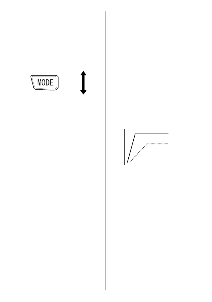
Suzuki Drive Mode Selector 4
Engine power characteristics can
be selected from 2 modes by
operating the drive mode selector
to suit rider’s preference in various riding conditions.
A
B
NOTE:
• Operating the Suzuki drive
mode selector while riding with
the throttle opened will change
the engine speed because of
engine power characteristics
change.
• The Suzuki drive mode indicator blinks when drive mode
change operation is failed.
• Turning off the ignition switch
or the engine stop switch will
return the drive mode to Amode. Start the engine and
reset the drive mode.
Suzuki drive mode selector
operation
Drive mode is preset at A-mode
when the ignition switch and the
engine stop switch are turned on.
At this time, the Suzuki drive
mode indicator shows nothing.
Follow the procedure below to
operate the Suzuki drive mode
selector.
1. Turn on the ignition switch and
the engine stop switch.
2. Push the Suzuki drive mode
selector until the Suzuki drive
mode indicator shows A.
3. Push the Suzuki drive mode
selector to change drive mode.
The Suzuki drive mode indicator indicates actual drive
mode.
Drive mode
Engine power
A
B
Throttle opening
A-mode
A-mode provides sharp throttle
response at all throttle opening
range to obtain maximum engine
power.
B-mode
B-mode provides soft throttle
response at all throttle opening
range by reducing engine power.
3-23
Page 45
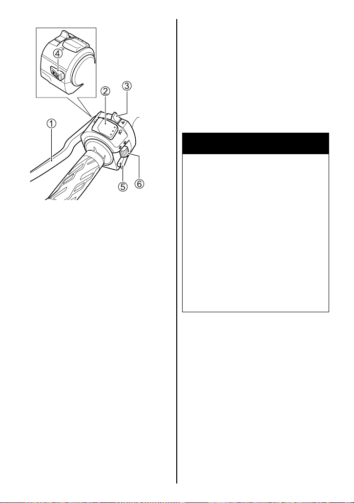
Horn Switch “” 5
Press the switch to sound the
horn.
Turn Signal Light Switch
“” 6
Moving the switch to the “”
position will flash the left turn signals. Moving the switch to the “”
position will flash the right turn
signals. The indicator light will
also flash intermittently. To cancel
turn signal operation, push the
switch in.
WARNING
Failure to use the turn signals,
and failure to turn off the turn
signals can be hazardous.
Other drivers may misjudge
your course and this may
result in an accident.
Always use the turn signals
when you intend to change
lanes or make a turn. Be sure
to turn off the turn signals after
completing the turn or lane
change.
3-24
Page 46
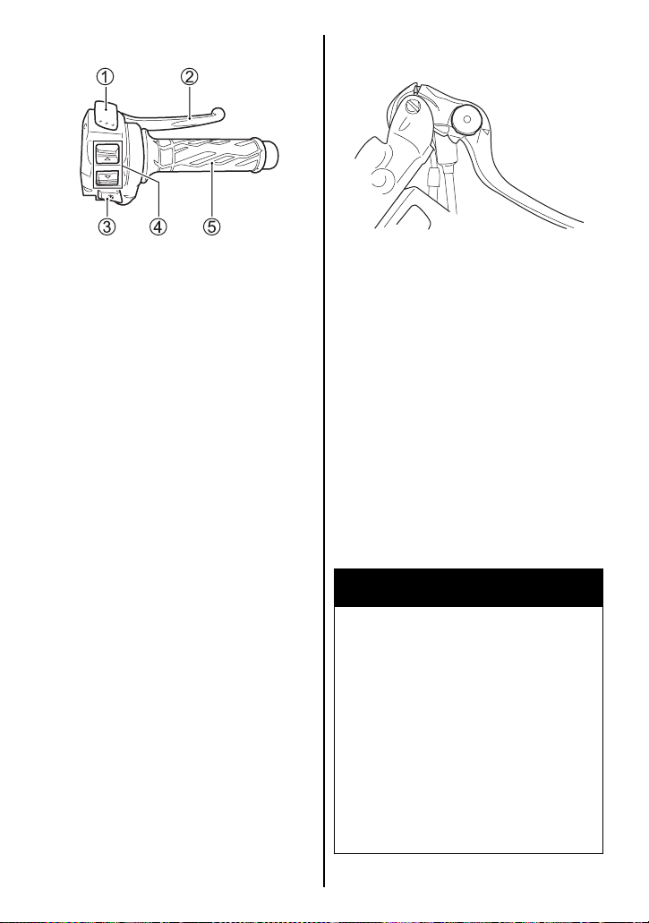
RIGHT HANDLEBAR
METER
Front Brake Lever Adjustment
Engine Stop Switch 1
“” position
The ignition circuit is off. The
engine cannot start or run.
“” position
The ignition circuit is on and the
engine can run.
Front Brake Lever 2
Apply the front brake by squeezing the front brake lever towards
the grip. The brake light will come
on when the lever is squeezed.
The distance between the throttle
grip and the front brake lever is
adjustable to 6 positions. To
change the position, push the
brake lever forward and turn the
adjuster to the desired position.
When changing the brake lever
position, always be sure the
adjuster stops in the proper position; a projection of the brake
lever pivot should fit into the
depression of the adjuster. This
motorcycle is delivered from the
factory with its adjuster set on
position 3.
WARNING
Adjusting the front brake lever
position while riding can be
hazardous. Removing a hand
from the handlebars can
reduce your ability to control
the motorcycle.
Never adjust the front brake
lever position while riding.
Keep both hands on the handlebars.
3-25
Page 47
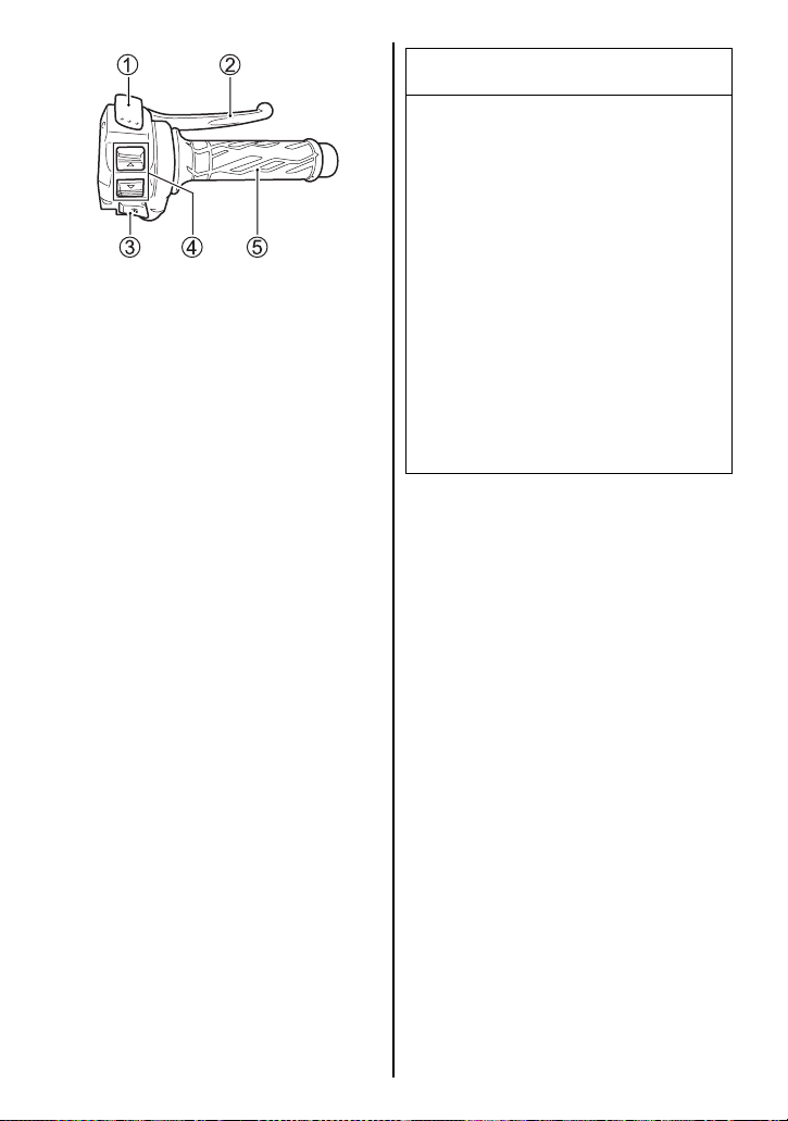
METER
Electric Starter Switch “” 3
Use this switch to operate the
starter motor. With the ignition
switch in the “ON” position, the
engine stop switch in the “”
position, and the transmission in
neutral, squeeze the clutch lever
and push the electric starter
switch to start the engine.
NOTE: This motorcycle has a
starter interlock system for the
ignition and starter circuit. The
engine can only be started if:
• The transmission is in neutral
and the clutch is disengaged,
or
• The transmission is in gear,
the side stand is fully up and
the clutch is disengaged.
NOTICE
Engaging the starter motor for
more than five seconds at a
time can damage the starter
motor and wiring harness from
overheating.
Do not engage the starter
motor for more than five seconds at a time. If the engine
does not start after several
attempts, check the fuel supply
and ignition system. Refer to
the TROUBLESHOOTING section in this manual.
NOTE: The headlight will go off
when the electric starter switch is
pushed.
3-26
Page 48

NOTICE
If the neutral indicator light and
the gear position indicator are
not giving proper indications,
starting the engine can cause
serious engine damage.
Before starting the engine,
make sure of the followings:
• When the neutral indicator
light comes on, the gear
position indicator should
indicate “0” (Neutral).
• When the neutral indicator
light goes off, the gear position indicator should indicate
either “1”, “2”, “3”, “4”, “5”
or “6”.
• If the neutral indicator light
and the gear position indicator are not working properly,
consult your Suzuki dealer.
Lap Time Counter Switch 4
To change the display, push the
lap time counter switch. Refer to
the INSTRUMENT PANEL section
for detail.
Throttle Grip 5
Engine speed is controlled by the
position of the throttle grip. Twist it
toward you to increase engine
speed. Turn it away from you to
decrease engine speed.
3-27
Page 49
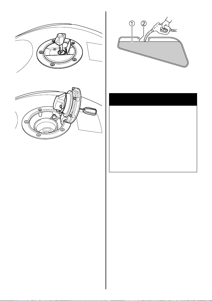
FUEL TANK CAP
1 Fuel level
2 Filler neck
WARNING
If you overfill the fuel tank, fuel
may overflow when it expands
due to engine heat or heating
by the sun. Fuel that overflows
can catch fire.
To open the fuel tank cap, insert
the ignition key into the lock and
turn it clockwise. With the key
inserted, lift up with the key and
open the fuel tank cap. To close
the fuel tank cap, push the cap
down firmly with the key in the cap
lock.
Use fresh gasoline when filling up
the fuel tank. Do not use bad gasoline which is contaminated with
dirt, dust, water or other liquid. Be
careful that dirt, dust or water do
not enter the fuel tank when refueling.
Stop adding fuel when the fuel
level reaches the bottom of the
filler neck.
3-28
Page 50
WARNING
Failure to follow safety precautions when refueling could
result in a fire or cause you to
breathe toxic fumes.
Refuel in a well ventilated area.
Make sure the engine is off and
avoid spilling fuel on a hot
engine. Do not smoke, and
make sure there are no open
flames or sparks in the area.
Avoid breathing gasoline
vapors. Keep children and pets
away when you refuel the
motorcycle.
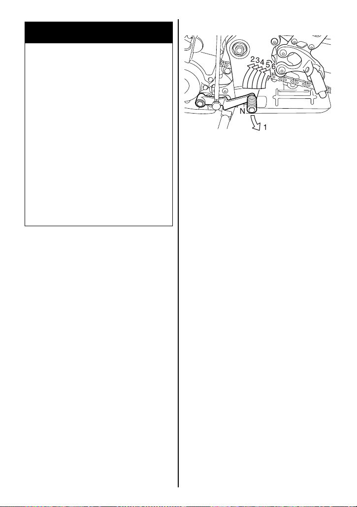
GEARSHIFT LEVER
This motorcycle has a 6-speed
transmission which operates as
shown. To shift properly, squeeze
the clutch lever and close the
throttle at the same time you
operate the gearshift lever. Lift the
gearshift lever to upshift and
depress the lever to downshift.
Neutral is located between 1st
and 2nd gear. When neutral is
desired, depress or lift the lever
halfway between 1st and 2nd
gear.
NOTE: When the transmission is
in neutral, the green indicator light
on the instrument panel will be lit.
However, even though the light is
illuminated, cautiously and slowly
release the clutch lever to make
sure that the transmission is positively in neutral.
3-29
Page 51
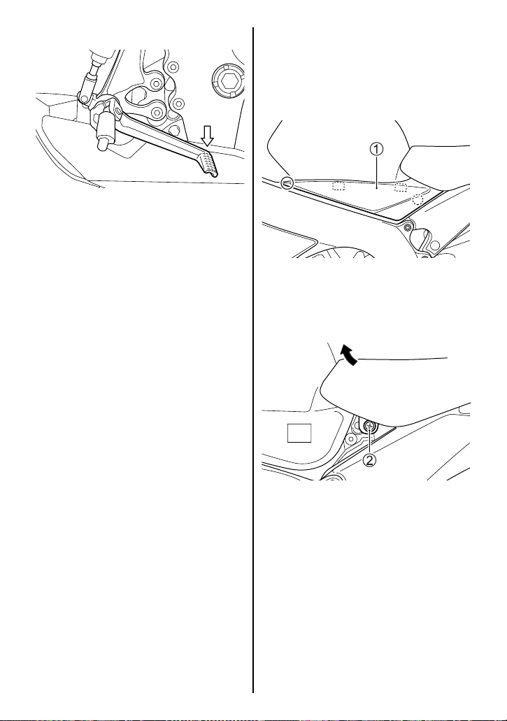
REAR BRAKE PEDAL
Depressing the rear brake pedal
will apply the rear disk brake. The
brake light will be illuminated
when the rear brake is operated.
SEAT LOCK AND HELMET HOLDERS
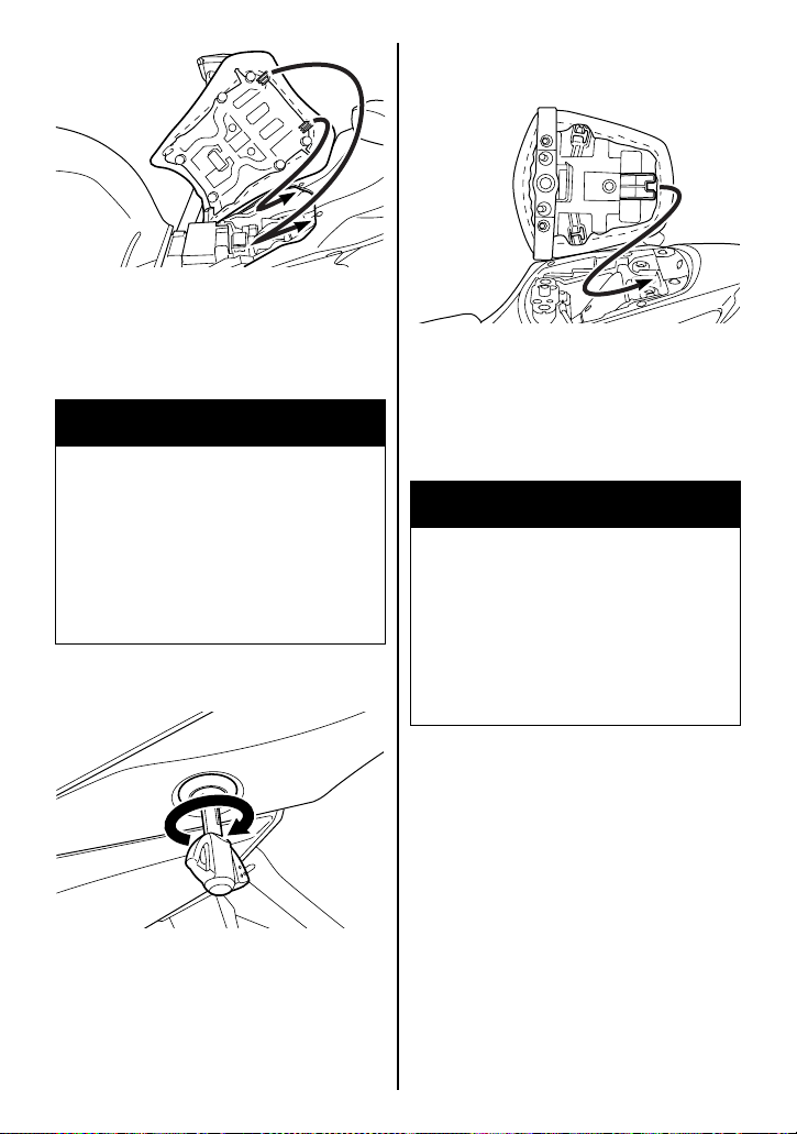
Front Seat
To remove the front seat.
1. Remove the fasteners.
Unhook the hooks. Remove
the right and left side frame
cover 1.
2. Remove the right and left
screws 2.
3. Raise the front end of the seat
and slide it forward.
3-30
Page 52
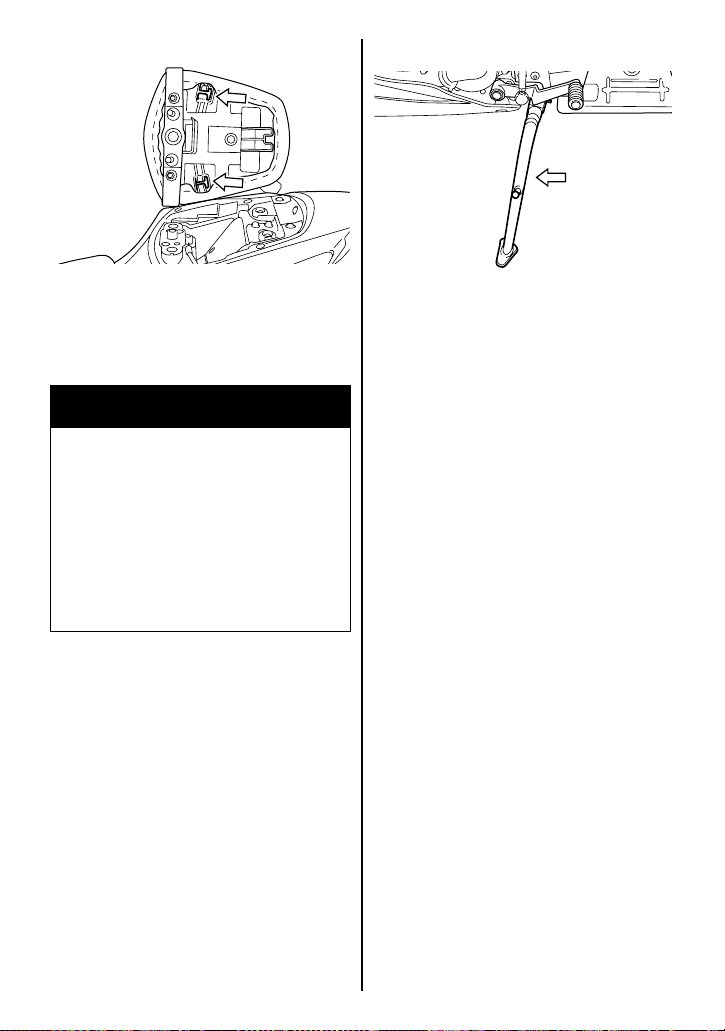
To reinstall the seat, slide the seat
hooks into the seat hook retainers
on the frame and tighten the bolts
securely.
WARNING
Failure to install the seat properly could allow the seat to
move and cause loss of rider
control.
Fasten the seat securely in its
proper position.
Raise the front end of the seat
and slide it forward.
To reinstall the seat, slide the seat
hooks into the seat hook retainers
and push down firmly until the
seat snaps into the locked position.
WARNING
Failure to install the seat properly could allow the seat to
move and cause loss of rider
control.
Rear Seat
The seat lock is located under the
left frame cover. To remove the
rear seat, insert the ignition key
into the lock and turn it clockwise.
Latch the seat securely in its
proper position.
3-31
Page 53
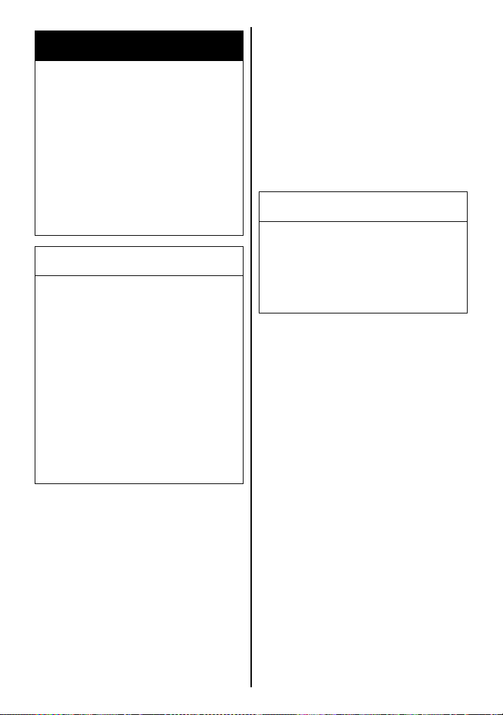
Helmet Holders
SIDE STAND
This motorcycle has helmet holders underneath the rear seat.
Hook your helmet on the helmet
holder and lock the seat.
WARNING
Riding with a helmet fastened
to the helmet holder can interfere with rider control.
Never carry a helmet fastened
to the helmet holder. Fix the
helmet securely atop the seat if
you must carry it.
An interlock system is provided to
cut off the ignition circuit when the
side stand is down and the transmission is in any gear other than
neutral.
The side stand/ignition interlock
system works as follows:
• If the side stand is down and
the transmission is in gear, the
engine can not be started.
• If the engine is running and the
transmission is shifted into
gear with the side stand down,
the engine will stop running.
• If the engine is running and the
side stand is put down with the
transmission in gear, the
engine will stop running.
3-32
Page 54
WARNING
Riding with the side stand
incompletely retracted can
result in an accident when you
turn left.
Check operation of the side
stand/ignition interlock system before riding. Always
retract the side stand completely before starting off.
NOTICE
If you do not take proper precautions when parking, the
motorcycle can fall over.
Park the motorcycle on firm,
level ground whenever possible. If you must park on an
incline, aim the front of the
motorcycle uphill and put the
transmission into 1st gear to
reduce the possibility of rolling
off the side stand.
SUSPENSION ADJUSTMENT
The standard settings for both the
front and rear suspensions are
selected to meet various riding
conditions such as low to high
motorcycle speed and light to
heavy load on the motorcycle.
The suspension settings can be
adjusted and fine-tuned according
to your preference.
NOTICE
Turning adjusters by force can
damage the suspensions.
Do not turn adjusters beyond
their natural limits.
3-33
Page 55

FRONT SUSPENSION
Spring Pre-load Adjustment
To set the spring pre-load adjuster
to the standard position, turn the
adjuster 1 counterclockwise until
it stops and turn the adjuster
clockwise 6 and 1/4 turns. Turn
the adjuster clockwise from the
standard position to stiffen the
spring pre-load. Turn the adjuster
counterclockwise to soften the
spring pre-load. The spring preload should be adjusted gradually
to fine-tune the suspension.
Adjust the right and left front forks
to the same setting.
Damping Force Adjustment
The rebound and compression
damping force can be individually
adjusted by turning the respective
adjusters. The rebound damping
force adjuster 2 and compression damping force adjuster 3
are located at the top of the front
suspension.
To adjust the damping force, set
the adjuster to the standard setting first and then adjust the
adjuster to the desired position.
To set the rebound damping force
adjuster to the standard position,
turn the adjuster clockwise until it
stops and then turn it counterclockwise 4 turns.
Turn the adjuster clockwise from
the standard position to stiffen the
damping force. Turn the adjuster
counterclockwise to soften the
damping force. The damping
force should be adjusted gradually, 1/8 turn at a time, to fine-tune
the suspension.
3-34
Page 56
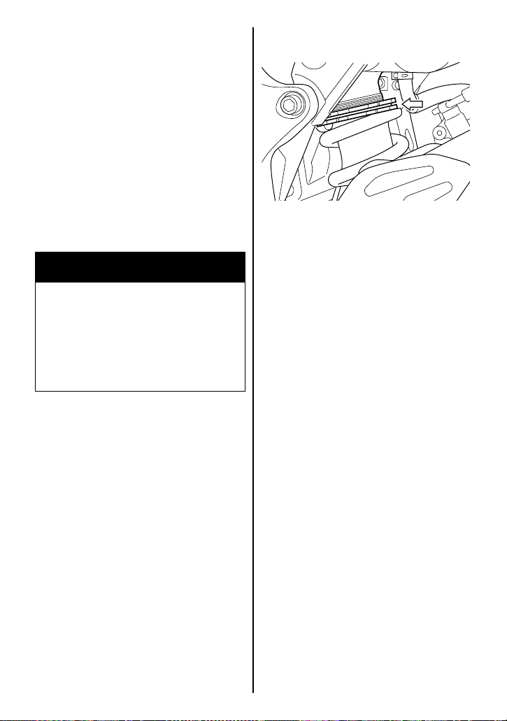
To set the compression damping
force adjuster to the standard
position, turn the adjuster clockwise until it stops and then turn it
counterclockwise 4 and 1/2 turns.
Turn the adjuster clockwise from
the standard position to stiffen the
damping force. Turn the adjuster
counterclockwise to soften the
damping force. The damping
force should be adjusted gradually, 1/8 turn at a time, to fine-tune
the suspension.
WARNING
Unequal suspension adjustment can cause poor handling
and instability.
Adjust the right and left front
forks to the same setting.
REAR SUSPENSION
Spring Pre-load Adjustment
This adjustment can be performed by changing the adjuster
ring position. However, Suzuki
recommends that this adjustment
be done by your authorized
Suzuki dealer, since a special tool
is needed for this job.
3-35
Page 57
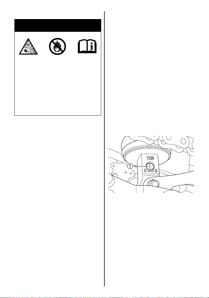
Rear Suspension Label
WARNING
This unit contains high-pressure nitrogen gas.
Mishandling can cause explosion.
• Keep away from fire and heat.
• Read owner’s manual for
more information.
NOTE: Ask your Suzuki dealer to
dispose of the rear suspension
unit.
Damping Force Adjustment
Three damping forces, rebound,
high stroke speed compression
and low stroke speed compression, can be individually adjusted
by turning the respective adjusters. The rebound damping force
adjuster 1 is located at the bottom of the rear suspension. The
high stroke speed and low stroke
speed compression damping
force adjusters 2, 3 are located
at the left side of the rear suspension.
To adjust the damping force, set
the adjuster to the standard setting first and then adjust the
adjuster to the desired position.
To set the rebound damping force
adjuster to the standard position,
turn the adjuster clockwise until it
stops and then turn it counterclockwise 2 and 3/4 turns.
3-36
Page 58
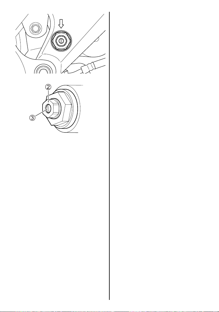
High stroke speed damping
force adjuster 2
To adjust the damping force, turn
the adjuster in fully and then turn
it out. The fully turned-in position
provides the stiffest damping
force and turning the adjuster out
will soften the damping force.
Count the number of turns from
the fully turned-in position. To set
the high stroke speed damping
force to the standard position, turn
the adjuster clockwise until it
stops and then turn it counterclockwise 2 and 3/4 turns.
Low stroke speed damping
force adjuster 3
To adjust the damping force, turn
the adjuster in fully and then turn
it out. The fully turned-in position
provides the stiffest damping
force and turning the adjuster out
will soften the damping force.
Count the number of turns from
the fully turned-in position. To set
the low stroke speed damping
force to the standard position, turn
the adjuster clockwise until it
stops and then turn it counterclockwise 1 and 3/4 turns.
Turn the adjuster clockwise from
the standard position to stiffen the
damping force. Turn the adjuster
counterclockwise to soften the
damping force. The damping
force should be adjusted gradually, 1/8 turn at a time, to fine-tune
the suspension.
3-37
Page 59
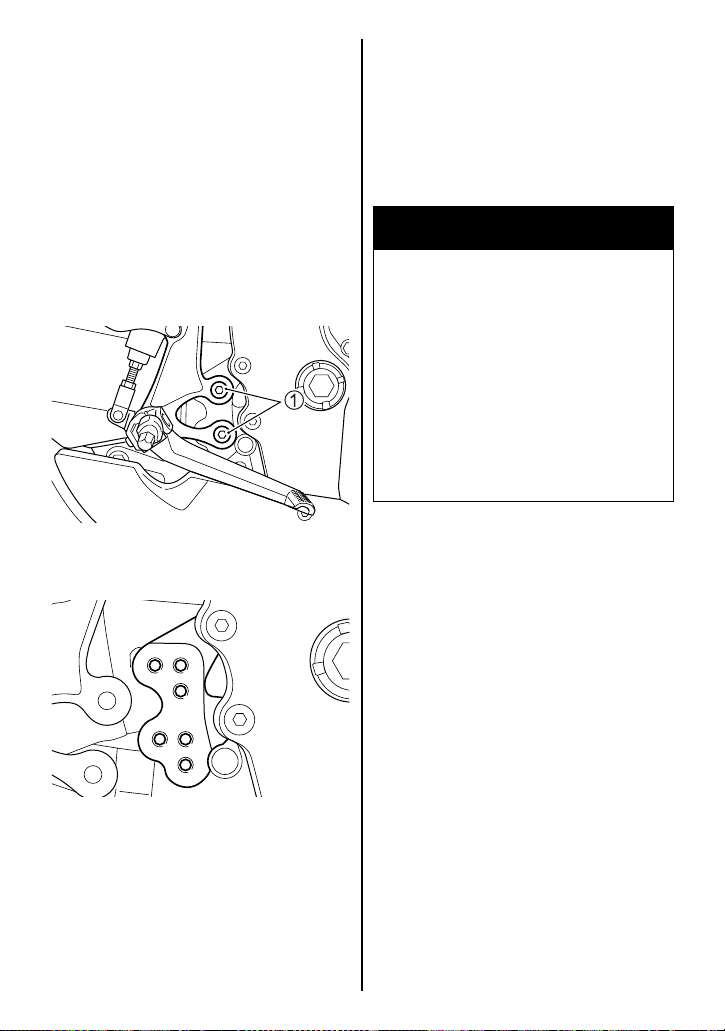
FOOTRESTS AND GEARSHIFT LEVER POSITION CHANGE
Right and left footrest position and
gearshift lever position can be
changed in three positions to sit in
a comfortable position.
Right Footrest and Rear Brake
Pedal
Change the right footrest position
and adjust brake lever position as
follows:
Footrest bracket
tightening torque:
23 N·m (2.3 kgf-m, 16.5 lbf-ft)
NOTE: Apply a drop of SUZUKI
THREAD LOCK “1342” to the
footrest mounting bolts
1.
WARNING
Failure to torque bolts and nuts
properly could lead to an accident.
Torque bolts and nuts to the
proper specifications. If you
are not sure of the proper procedure, have your authorized
Suzuki dealer or a qualified
mechanic do this.
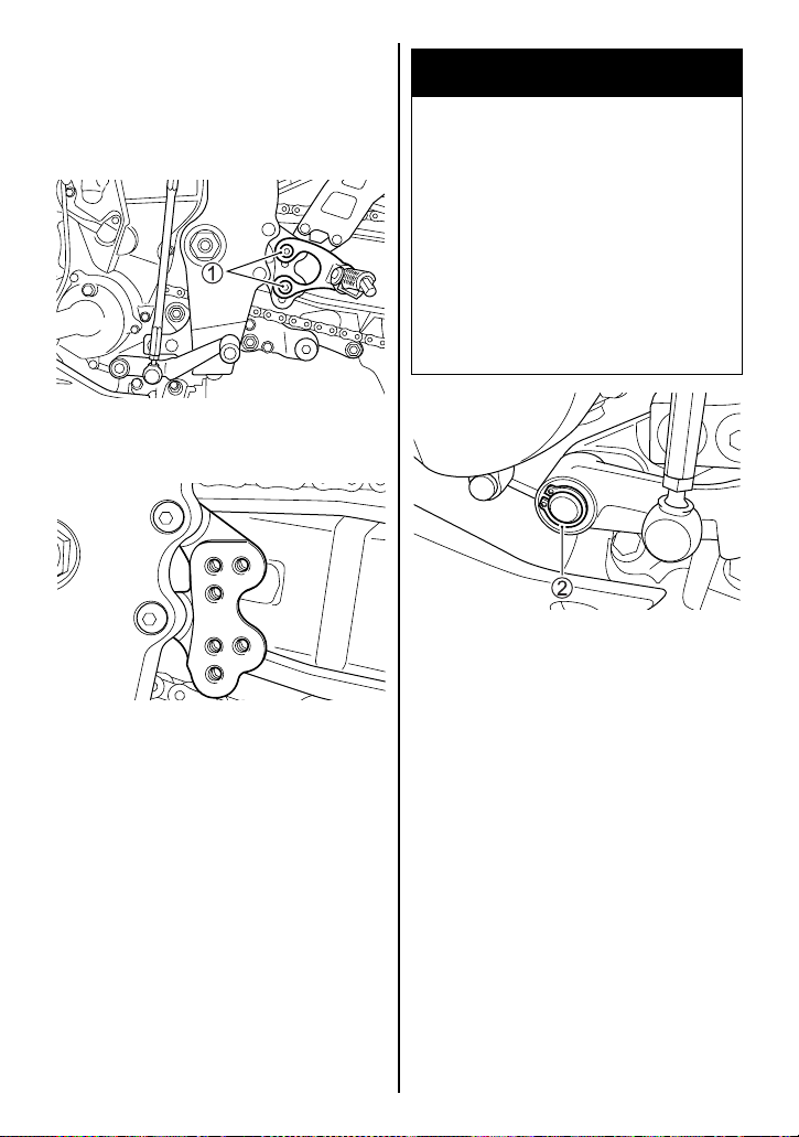
1. Loosen the two footrest
mounting bolts 1.
2. Move the footrest bracket and
remount it to the desired position.
3. Tighten the bolts to the specified torque.
4. Adjust the rear brake pedal
height by referring to the
REAR BRAKE PEDAL
ADJUSTMENT section in this
manual.
3-38
Page 60
Left Footrest and Gearshift
Lever
Change the left footrest position
and gearshift lever position as follows:
1. Loosen the two footrest
mounting bolts 1.
WARNING
Failure to torque bolts and nuts
properly could lead to an accident.
Torque bolts and nuts to the
proper specifications. If you
are not sure of the proper procedure, have your authorized
Suzuki dealer or a qualified
mechanic do this.
4. Remove the circlip 2 with
snap ring pliers. Remove the
gearshift lever.
2. Move the footrest bracket and
remount it to the desired position.
3. Tighten the bolts to the specified torque.
Footrest bracket
tightening torque:
23 N·m (2.3 kgf-m, 16.5 lbf-ft)
NOTE: Apply a drop of SUZUKI
THREAD LOCK “1342” to the
footrest mounting bolts
1.
NOTE: Replace with a new circlip
when refitting it.
3-39
Page 61
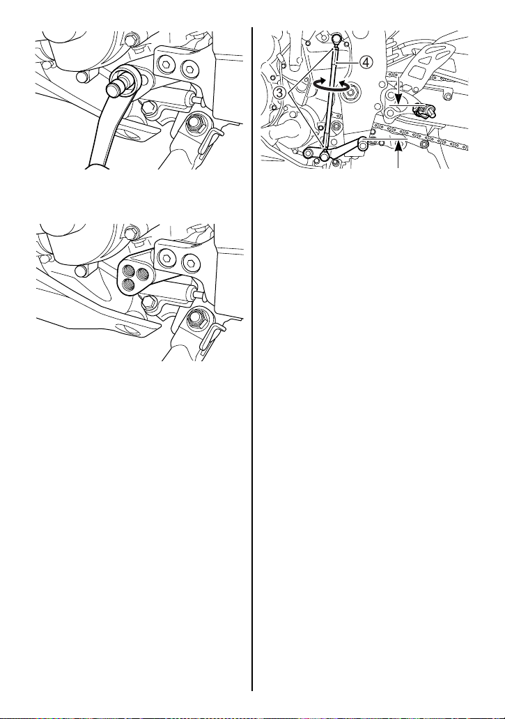
5. Loosen the gearshift lever
pivot.
6. Move the gearshift lever pivot
and refit it to the desired position. Tighten the pivot bolt
securely.
65 – 75 mm
(2.6 – 3.0 in)
7. Loosen the lock nuts 3. Turn
the rod 4 and adjust the gearshift lever position.
8. Rotate the rod 4 to locate the
gearshift lever 65 – 75 mm
(2.6 – 3.0 in) below the top
face of the footrest.
9. Tighten the lock nuts to secure
the rod in the proper position.
3-40
Page 62

BREAK-IN AND INSPECTION
BEFORE RIDING
BREAK-IN ............................................................................................................ 4-2
INSPECTION BEFORE RIDING .......................................................................... 4-3
4
4-1
Page 63
BREAK-IN AND
INSPECTION BEFORE
RIDING
BREAK-IN
The first 800 km (500 miles) is the
most important in the life of your
motorcycle. Proper operation during this break-in period will help
assure maximum life and performance from your new motorcycle.
The following guidelines explain
proper break-in procedures.
Maximum Engine Speed
Recommendation
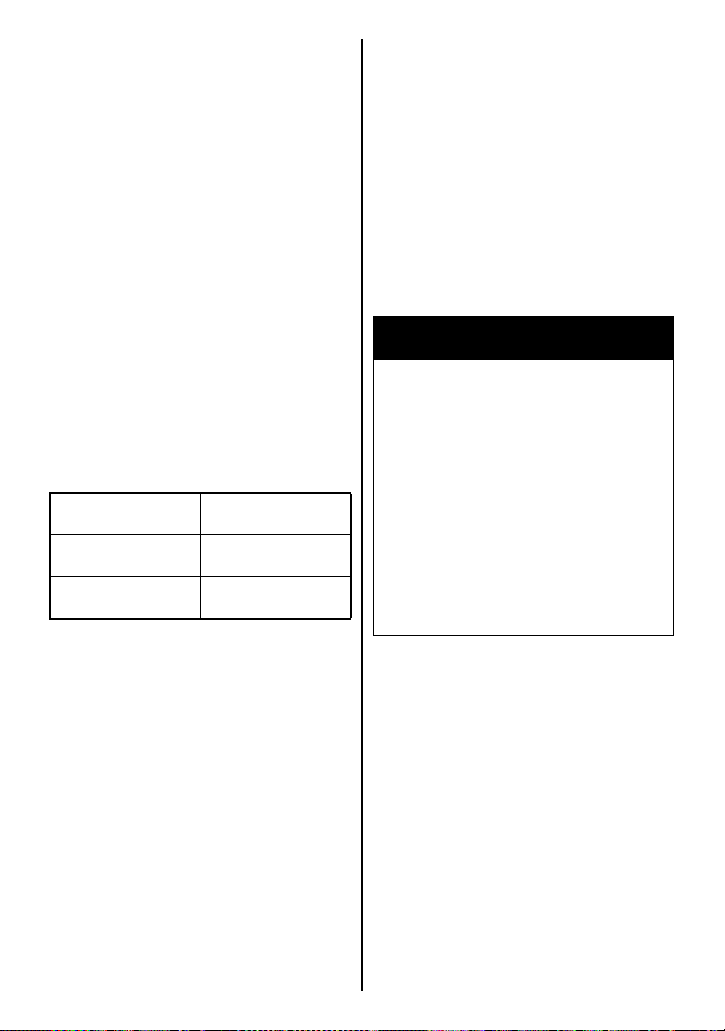
The table below shows the maximum engine speed recommendation during the break-in period.
Initial 800 km
(500 miles)
Up to 1600 km
(1000 miles)
Over 1600 km
(1000 miles)
Below
7500 r/min
Below
11000 r/min
Below
15250 r/min
Breaking in the New Tires
New tires need proper break-in to
assure maximum performance,
just as the engine does. Wear- in
the tread surface by gradually
increasing your cornering lean
angles over the first 160 km (100
miles) before attempting maximum performance. Avoid hard
acceleration, hard cornering, and
hard braking for the first 160 km
(100 miles).
.
WARNING
Failure to perform break-in of
the tires could cause tire slip
and loss of control.
Use extra care when riding on
new tires. Perform proper
break-in of the tires as
described in this section and
avoid hard acceleration, hard
cornering, and hard braking for
the first 160 km (100 miles).
Vary the Engine Speed
Vary the engine speed during the
break-in period. This allows the
parts to “load” (aiding the mating
process) and then “unload”
(allowing the parts to cool).
Although it is essential to place
some stress on the engine components during break-in, you must
be careful not to load the engine
too much.
4-2
Page 64
Observe Your Initial and
Most Critical Service
The initial service (break-in maintenance) is the most important
service your motorcycle will
receive. During break-in operation, all of the engine components
will have mated together and
seated. Maintenance required as
part of the initial service includes
correction of all adjustments,
tightening of all fasteners and
replacement of dirty oil. Timely
performance of this service will
help make sure you get the best
service life and performance from
the engine.
NOTE: The 1000 km (600 miles)
service should be performed as
outlined in the INSPECTION AND
MAINTENANCE section of this
Owner’s Manual. Pay particular
attention to the CAUTION and
WARNING messages in that section.
INSPECTION BEFORE RIDING
WARNING
Failure to inspect your motorcycle before riding and to properly maintain your motorcycle
increases the chances of an
accident or equipment damage.
Always inspect your motorcycle each time you use it to
make sure it is in safe operating condition. Refer to the
INSPECTION AND MAINTENANCE section in this owner’s
manual.
WARNING
If you operate this motorcycle
with improper tires or improper
or uneven tire pressure, you
may lose control of the motorcycle. This will increase your
risk of an accident.
Always use tires of the size and
type specified in this owner’s
manual. Always maintain
proper tire pressure as
described in the INSPECTION
AND MAINTENANCE section.
4-3
Page 65
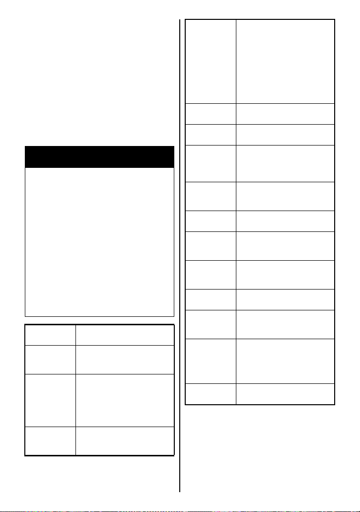
Check the condition of the motorcycle to help make sure that you
do not have mechanical problems
or get stranded somewhere when
you ride. Before riding the motorcycle, be sure to check the following items. Be sure your
motorcycle is in good condition for
the personal safety of the rider,
passenger and protection of the
motorcycle.
WARNING
Checking maintenance items
when the engine is running can
be hazardous. You could be
severely injured if your hands
or clothing get caught in moving engine parts.
Shut the engine off when performing maintenance checks,
except when checking the
lights, engine stop switch, and
throttle.
WHAT TO
CHECK
Steering • Smoothness
Throttle
( 7-26)
Clutch
( 7-28)
CHECK FOR:
• No restriction of movement
• No play or looseness
• Correct play in the throttle
cable
• Smooth operation and
positive return of the
throttle grip to the closed
position
• Correct lever play
• Smooth and progressive
action
Brakes
( 3-25,
3-30, 7-34)
Suspension
( 3-33)
Fuel
( 3-11)
Drive chain
( 7-30)
Tires
( 7-39)
Engine oil
( 7-20)
Cooling
system
( 7-28)
Lighting
( 3-5,
3-8, 3-22)
Horn
( 3-24)
Engine stop
switch
( 3-25)
Side stand/
Ignition
interlock
system
( 7-42)
Windshield
( 9-6)
• Proper pedal and lever
operation
• Fluid level in the reservoir
to be above “LOWER” line
• Correct pedal and lever
play
• No “sponginess”
• No fluid leakage
• Brake pads not worn down
to the limit line
Smooth movement
Enough fuel for the planned
distance of operation
• Correct tension or slack
• Adequate lubrication
• No excessive wear or
damage
• Correct pressure
• Adequate tread depth
• No cracks or cuts
Correct level
• Proper coolant level
• No coolant leakage
Operation of all lights and
indicators
Correct function
Correct function
Proper operation
Good visibility
4-4
Page 66

RIDING TIPS
STARTING THE ENGINE .................................................................................... 5-2
STARTING OFF ................................................................................................... 5-4
USING THE TRANSMISSION ............................................................................. 5-5
RIDING ON HILLS ............................................................................................... 5-6
STOPPING AND PARKING ................................................................................ 5-7
CARRYING A PASSENGER ............................................................................... 5-8
5
5-1
Page 67

RIDING TIPS
STARTING THE ENGINE
Before attempting to start the
engine, make sure:
1. The transmission is in neutral.
2. The engine stop switch is in
the “” position.
NOTICE
If the neutral indicator light and
the gear position indicator are
not giving proper indications,
starting the engine can cause
serious engine damage.
NOTE: This motorcycle has a
starter interlock system for the
ignition and starter circuit. The
engine can only be started if:
• The transmission is in neutral
and the clutch is disengaged,
or
• The transmission is in gear,
the side stand is fully up and
the clutch is disengaged.
NOTE: The fuel supply system
stops the engine when the motorcycle is overturned. Turn off the
ignition switch before restarting
the engine.
Before starting the engine,
make sure of the followings:
• When the neutral indicator
light comes on, the gear
position indicator should
indicate “0” (Neutral).
• When the neutral indicator
light goes off, the gear position indicator should indicate
either “1”, “2”, “3”, “4”, “5”
or “6”.
• If the neutral indicator light
and the gear position indicator are not working properly,
consult your Suzuki dealer.
5-2
Page 68
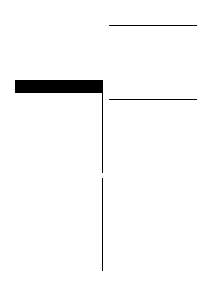
When the Engine is Cold or
Warm:
Close the throttle completely and
push the electric starter switch.
When a Cold or Warm Engine is
Hard to Start:
Open the throttle approximately 1/8
turn and push the electric starter
switch.
NOTICE
Running the engine too long
without riding may cause the
engine to overheat. Overheating can result in damage to
internal engine components
and discoloration of exhaust
pipes.
WARNING
Exhaust gas contains carbon
monoxide, a dangerous gas
that is difficult to detect
because it is colorless and
odorless. Breathing carbon
monoxide can cause death or
severe injury.
Never start the engine or let it
run indoors or where there is
little or no ventilation.
NOTICE
After starting the engine, opening the throttle or running the
motorcycle with the oil pressure indicator light turned on
may adversely affect the
engine.
Make sure that the oil pressure
indicator light has turned off
before operating the throttle or
running the motorcycle.
Shut the engine off if you cannot begin your ride promptly.
5-3
Page 69
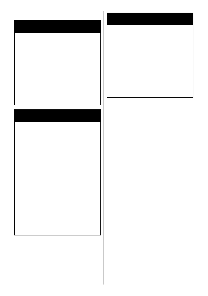
STARTING OFF
WARNING
Riding at excessive speeds
increases your chances of losing control of the motorcycle,
which can result in an accident.
WARNING
Sudden side winds, which can
occur when being passed by
larger vehicles, at tunnel exits
or in hilly areas, can cause you
to lose control of the motorcycle.
Always ride at a speed that is
proper for the terrain, visibility
and operating conditions, and
your skills and experience.
WARNING
If you remove even one hand or
foot from the motorcycle, you
can reduce your ability to control the motorcycle. This could
cause you to lose your balance
and fall off the motorcycle. If
you remove a foot from a footrest, your foot or leg may come
in contact with the rear wheel.
This could injure you or cause
an accident.
Always keep both hands on the
handlebars and both feet on
the footrests of your motorcycle during operation.
Reduce your speed and be
alert to the possibility of sudden side winds.
Make sure that the side stand is in
the fully up position. Squeeze the
clutch lever and pause momentarily. Engage first gear by
depressing the gearshift lever
downward. Turn the throttle grip
toward you and at the same time
release the clutch lever gently and
smoothly. As the clutch engages,
the motorcycle will start moving
forward. To shift to the next higher
gear, accelerate gently, then close
the throttle and squeeze the
clutch lever simultaneously. Lift
the gear shift lever upward to
select the next gear and release
the clutch lever as you open the
throttle again. Select higher gears
in this manner until top gear is
reached.
NOTE: This motorcycle has a side
stand/ignition interlock system. If
you shift the transmission into
gear when the side stand is down,
the engine will stop running.
5-4
Page 70
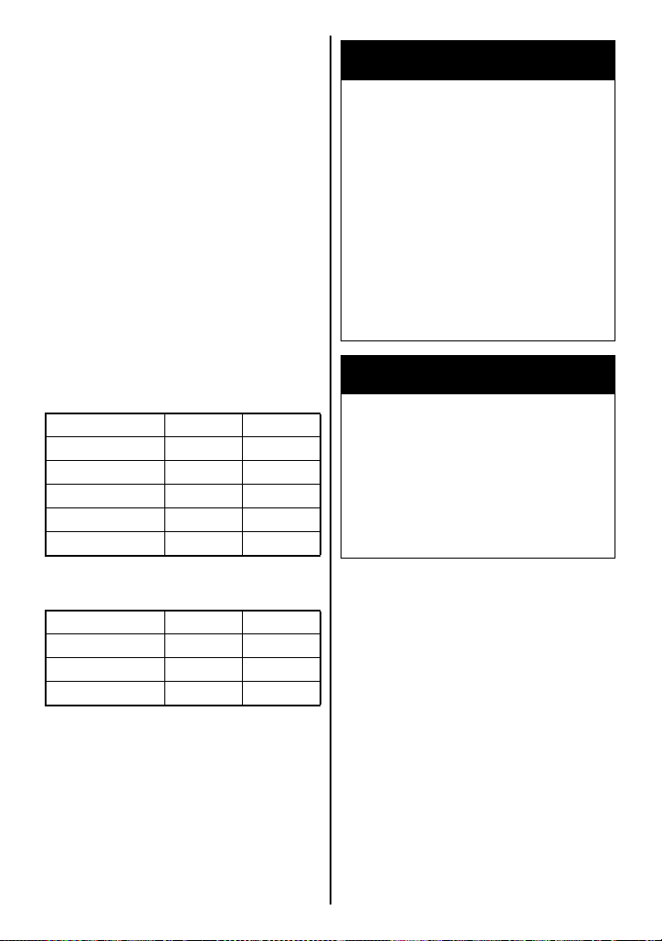
USING THE TRANSMISSION
The transmission is provided to
keep the engine operating
smoothly in its normal operating
speed range. The gear ratios
have been carefully chosen to
meet the characteristics of the
engine. The rider should always
select the most suitable gear for
the prevailing conditions. Never
slip the clutch to control road
speed, but rather downshift to
allow the engine to run within its
normal operational range. The
table below shows the approximate speed range for each gear.
WARNING
Downshifting when engine
speed is too high can:
• cause the rear wheel to skid
and lose traction due to
increased engine braking,
resulting in an accident; or
• force the engine to overrev in
the lower gear, resulting in
engine damage.
Reduce speed before downshifting.
Shifting up schedule
Gear position mph km/h
1st
→
2nd 12 20
2nd → 3rd 19 30
→
4th 25 40
3rd
4th
→
5th 31 50
5th → 6th 37 60
Shifting down schedule
Gear position mph km/h
6th → 5th 31 50
5th → 4th 25 40
→
3rd 19 30
4th
Disengage the clutch when the
motorcycle speed drops below 12
mph (20 km/h).
WARNING
Downshifting while the motorcycle is leaned over in a corner
may cause rear wheel skid and
loss of control.
Reduce your speed and downshift before entering a corner.
5-5
Page 71

NOTICE
Revving the engine into the red
zone can cause severe engine
damage.
Never allow the engine to rev
into the red zone in any gear.
NOTICE
Improper gearshift lever operation can damage the transmission.
• Do not rest your foot on the
gearshift lever.
• Do not use force to shift
gears.
RIDING ON HILLS
• When climbing steep hills, the
motorcycle may begin to slow
down and show lack of power.
At this point you should shift to
a lower gear so that the engine
will again be operating in its
normal power range. Shift rapidly to prevent the motorcycle
from losing momentum.
• When descending a long,
steep slope, use the engine
compression to assist the
brakes by shifting to a lower
gear. Continuous brake application can overheat the brakes
and reduce their effectiveness.
• Be careful, however, not to
allow the engine to overrev.
5-6
Page 72
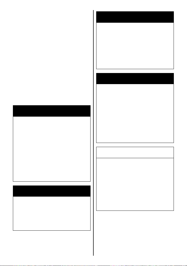
STOPPING AND PARKING
1. Twist the throttle grip away
from yourself to close the
throttle completely.
2. Apply the front and rear brakes
evenly and at the same time.
3. Downshift through the gears
as road speed decreases.
4. Select neutral with the clutch
lever squeezed toward the grip
(disengaged position) when
the motorcycle is almost completely stopped. The neutral
position can be confirmed by
observing the neutral indicator
light.
WARNING
Inexperienced riders tend to
underutilize the front brake.
This can cause excessive stopping distance and lead to a collision. Using only the front or
rear brake can cause skidding
and loss of control.
Apply both brakes evenly and
at the same time.
WARNING
Hard braking while turning may
cause wheel skid and loss of
control.
WARNING
Hard braking on wet, loose,
rough, or other slippery surfaces can cause wheel skid
and loss of control.
Brake lightly and with care on
slippery or irregular surfaces.
WARNING
Following another vehicle too
closely can lead to a collision.
As vehicle speeds increase,
stopping distance increases
progressively.
Always maintain a safe stopping distance between you and
the vehicle in front of you.
NOTICE
Holding the motorcycle
stopped with throttle and
clutch lever operation on
inclines can damage the motorcycle’s clutch.
Use the brakes when stopping
the motorcycle on inclines.
Brake before you begin to turn.
5-7
Page 73

5. Park the motorcycle on a firm,
flat surface where it will not fall
over.
CAUTION
A hot muffler can cause severe
burns. The muffler will be hot
enough to cause burns for
some time after stopping the
engine.
Park the motorcycle where
pedestrians or children are not
likely to touch the muffler.
NOTE: If the motorcycle is to be
parked on the side stand on a
slight slope, the front end of the
motorcycle should face “up” the
incline to avoid rolling forward off
the side stand. You may leave the
motorcycle in 1st gear to help prevent it from rolling off the side
stand. Shift to neutral before starting the engine.
CARRYING A PASSENGER
Before you invite someone to be a
passenger on your motorcycle,
you need to be thoroughly familiar
with motorcycle operation. Adjust
tire pressures and suspension
according to the Tire Pressure
and Loading section and the Suspension section of this manual.
The passenger should always
hold onto your waist or hips, or
onto the seat strap or grab bar, as
equipped. Ask your passenger
not to make any sudden movements. When you lean going
around a corner, the passenger
should lean with you. The passenger should always keep his or her
feet on the footrests, even when
you are stopped at a light.
To help prevent burn injuries,
warn your passenger not to contact the muffler when mounting or
dismounting your motorcycle.
6. Turn the ignition switch to the
“OFF” position.
7. Turn the handlebars all the
way to the left and lock the
steering for security.
8. Remove the ignition key.
NOTE: If an optional anti-theft
lock such as a U-shape lock,
brake disk lock or chain is used to
avoid theft, be sure to remove the
anti-theft lock before moving the
motorcycle.
5-8
Page 74

ACCESSORY USE AND
MOTORCYCLE LOADING
ACCESSORY USE .............................................................................................. 6-2
ACCESSORY INSTALLATION GUIDELINES .................................................... 6-2
LOADING LIMIT .................................................................................................. 6-3
LOADING GUIDELINES ...................................................................................... 6-4
MODIFICATION ................................................................................................... 6-4
6
6-1
Page 75

ACCESSORY USE AND
MOTORCYCLE LOADING
ACCESSORY USE
The addition of unsuitable accessories can lead to unsafe operating conditions. It is not possible
for Suzuki to test each accessory
on the market or combinations of
all the available accessories; however, your dealer can assist you in
selecting quality accessories and
installing them correctly. Use
extreme caution when selecting
and installing the accessories on
your motorcycle and consult your
Suzuki dealer if you have any
questions.
WARNING
Improper installation of accessories or modification of the
motorcycle may cause
changes in handling which
could lead to an accident.
ACCESSORY INSTALLATION GUIDELINES
• Install aerodynamic-affecting
accessories, such as a fairing,
windshield, backrests, saddlebags, and travel trunks, as low
as possible, as close to the
motorcycle and as near the
center of gravity as is feasible.
Check that the mounting
brackets and other attachment hardware are rigidly
mounted.
• Inspect for proper ground
clearance and bank angle.
Inspect that the accessory
does not interfere with the
operation of the suspension,
steering or other control operations.
Never use improper accessories, and make sure that any
accessories that are used are
properly installed. All parts and
accessories added to the
motorcycle should be genuine
Suzuki parts or their equivalent
designed for use on this motorcycle. Install and use them
according to their instructions.
If you have any questions, contact your Suzuki dealer.
6-2
Page 76

• Accessories fitted to the handlebars or the front fork area
can create serious stability
problems. This extra weight
will cause the motorcycle to be
less responsive to your steering control. The weight may
also cause oscillations in the
front end and lead to instability
problems. Accessories added
to the handlebars or front fork
of the machine should be as
light as possible and kept to a
minimum.
• Select an accessory which
does not limit the freedom of
rider movement.
• Select an electric accessory
which does not exceed motorcycle’s electrical system
capacity. Severe overloads
may damage the wiring harness or create hazardous situations.
• Do not pull a trailer or sidecar.
This motorcycle is not
designed to pull a trailer or
sidecar.
LOADING LIMIT
WARNING
Overloading or improper loading can cause loss of motorcycle control and an accident.
Follow loading limits and loading guidelines in this manual.
• Never exceed the G.V.W.
(Gross Vehicle Weight) of this
motorcycle. The G.V.W. is the
combined weight of the
machine, accessories, payload, rider and passenger.
When selecting your accessories, keep in mind the weight of
the rider as well as the weight
of the accessories. The additional weight of the accessories may not only create an
unsafe riding condition but
may also affect the riding stability.
G.V.W.: 380 kg (835 lbs)
at the tire pressure (cold)
Front: 250 kPa
(2.50 kgf/cm
Rear: 290 kPa
(2.90 kgf/cm2, 42 psi)
2
, 36 psi)
6-3
Page 77

LOADING GUIDELINES
This motorcycle is primarily
intended to carry small items
when you are not riding with a
passenger. Follow the loading
guidelines below:
• Balance the load between the
left and right side of the motorcycle and fasten it securely.
• Keep cargo weight low and as
close to the center of the
motorcycle as possible.
• Do not attach large or heavy
items to the handlebars, front
forks or rear fender.
• Check that both tires are properly inflated to the specified
tire pressure for your loading
conditions. Refer to page 7-40.
• Improperly loading your motorcycle can reduce your ability to
balance and steer the motorcycle. You should ride at
reduced speeds, less than 130
km/h (80 mph), when the
cargo is loaded or accessory
is fitted.
• Adjust suspension setting as
necessary.
WARNING
Placing objects in the space
behind the fairing can interfere
with steering and can cause
loss of control.
MODIFICATION
Modification of the vehicle or
removal of original equipment
may render the vehicle unsafe or
illegal. Obey all applicable regulations in your area including federal
and state regulations regarding
environmental protection.
Suzuki’s limited warranties may
not cover damage caused by
modifications that would change
the original vehicle specifications
including, without limitation, modifications of any emission-related
parts such as the carburetor(s),
fuel injection system components,
the engine control module, air
suction system components, the
catalytic converter (if equipped),
evaporative emission control system components (such as the carbon canister, fuel tank, fuel hoses
and vapor hoses), etc.
It is strictly prohibited to modify a vehicle by installing parts
that can affect emissions control, except in accordance with
very specific U.S. Environmental Protection Agency and California Air Resources Board
regulations.
Do not carry any objects in the
space behind the fairing.
6-4
Page 78
The frame of this motorcycle is
made of an aluminum alloy.
Therefore, never make any modifications such as drilling or welding to the frame as it weakens the
frame significantly. This could
result in an unsafe vehicle operating condition and subsequent
accident. Suzuki will not be
responsible in any way for personal injury or damage to the
motorcycle caused by frame modifications.
Bolt-on-accessories that do not
modify the frame in any way may
be installed, provided that you do
not exceed the loading limit
described in this section.
WARNING
Modification to an aluminum
alloy frame, such as drilling or
welding, weakens the frame.
This could result in an unsafe
operating condition and may
lead to an accident.
Never make any modifications
to the frame.
6-5
Page 79
Page 80

INSPECTION AND MAINTENANCE
MAINTENANCE SCHEDULE .............................................................................. 7-2
TOOLS ................................................................................................................. 7-6
STEERING DAMPER MAINTENANCE ...............................................................7-6
LUBRICATION POINTS ...................................................................................... 7-7
BATTERY ............................................................................................................ 7-8
AIR CLEANER ................................................................................................... 7-10
SPARK PLUGS .................................................................................................7-14
ENGINE OIL ....................................................................................................... 7-20
ENGINE IDLE SPEED INSPECTION ................................................................ 7-26
THROTTLE CABLE PLAY ................................................................................ 7-26
FUEL HOSE ....................................................................................................... 7-27
CLUTCH ADJUSTMENT ................................................................................... 7-28
ENGINE COOLANT ........................................................................................... 7-28
DRIVE CHAIN .................................................................................................... 7-30
BRAKES ............................................................................................................ 7-34
TIRES ................................................................................................................. 7-39
SIDE STAND/IGNITION INTERLOCK SYSTEM ............................................... 7-42
FRONT WHEEL REMOVAL .............................................................................. 7-43
REAR WHEEL REMOVAL ................................................................................ 7-46
LIGHT BULB REPLACEMENT ......................................................................... 7-49
FUSES ............................................................................................................... 7-55
CATALYTIC CONVERTER ............................................................................... 7-57
7
7-1
Page 81

INSPECTION AND
MAINTENANCE
MAINTENANCE, REPLACEMENT OR REPAIR OF THE
EMISSION CONTROL DEVICES
AND SYSTEMS MAY BE PERFORMED BY ANY MOTORCYCLE REPAIR ESTABLISHMENT
OR INDIVIDUAL USING ANY
MOTORCYCLE PART WHICH
HAS BEEN CERTIFIED UNDER
THE PROVISIONS IN THE
CLEAN AIR ACT Sec. 207 (a)(2).
MAINTENANCE SCHEDULE
It is very important to inspect and
maintain your motorcycle regularly. Follow the guidelines in the
chart. The intervals between periodic services in kilometers, miles
and months are shown. At the
end of each interval, be sure to
perform the maintenance listed.
WARNING
Improper maintenance or failure to perform recommended
maintenance can lead to an
accident.
Keep your motorcycle in good
condition. Ask your Suzuki
dealer or a qualified mechanic
to perform the maintenance
items marked with an asterisk
(*). You may perform the
unmarked maintenance items
by referring to the instructions
in this section, if you have
mechanical experience. If you
are not sure how to do any of
the jobs, ask your Suzuki
dealer to do the maintenance.
7-2
Page 82
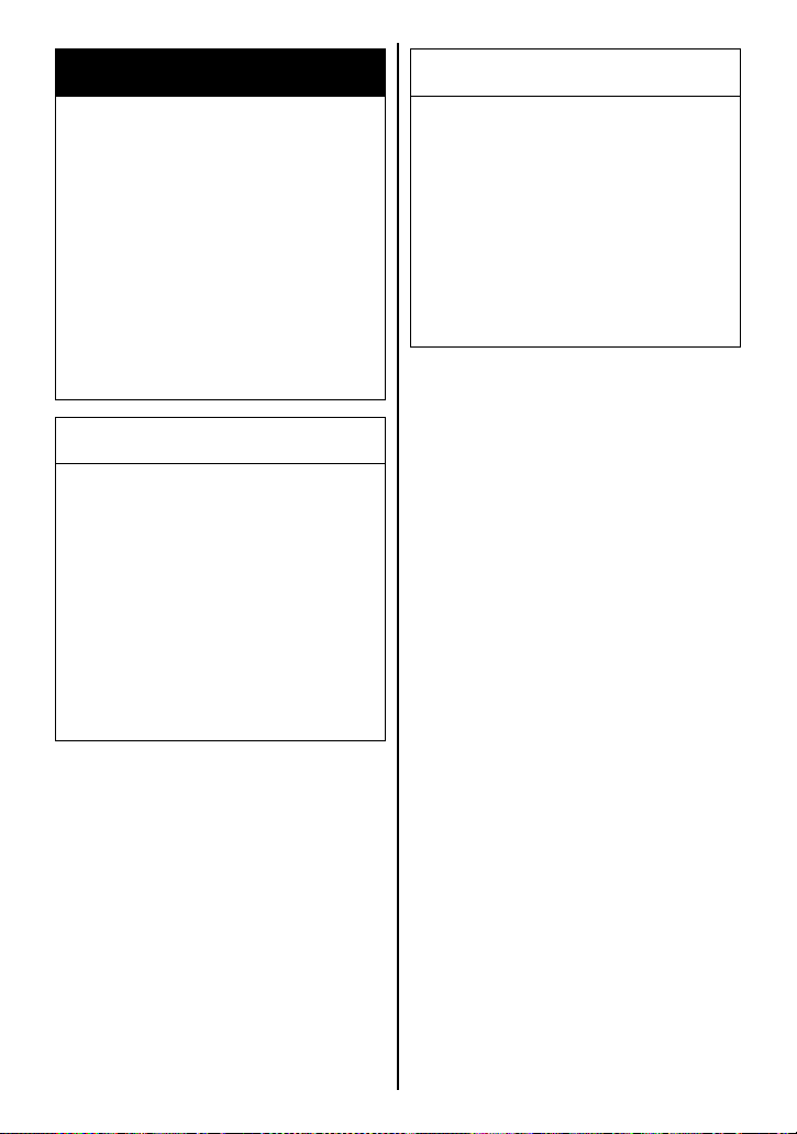
WARNING
Exhaust gas contains carbon
monoxide, a dangerous gas
that is difficult to detect
because it is colorless and
odorless. Breathing carbon
monoxide can cause death or
severe injury.
Never start the engine or let it
run indoors or where there is
little or no ventilation.
NOTICE
Servicing electric parts with
the ignition switch in the “ON”
position can damage the electric parts when the electric circuit is shorted.
Turn off the ignition switch
before servicing the electric
parts to avoid short-circuit
damage.
NOTICE
Poorly-made replacement parts
can cause your motorcycle to
wear more quickly and may
shorten its useful life.
When replacing parts on your
vehicle, use only genuine
Suzuki replacement parts or
their equivalent.
NOTE: The MAINTENANCE
CHART specifies the minimum
requirements for maintenance. If
you use your motorcycle under
severe conditions, perform maintenance more often than shown in
the chart. If you have any questions regarding maintenance
intervals, consult your Suzuki
dealer or a qualified mechanic.
7-3
Page 83
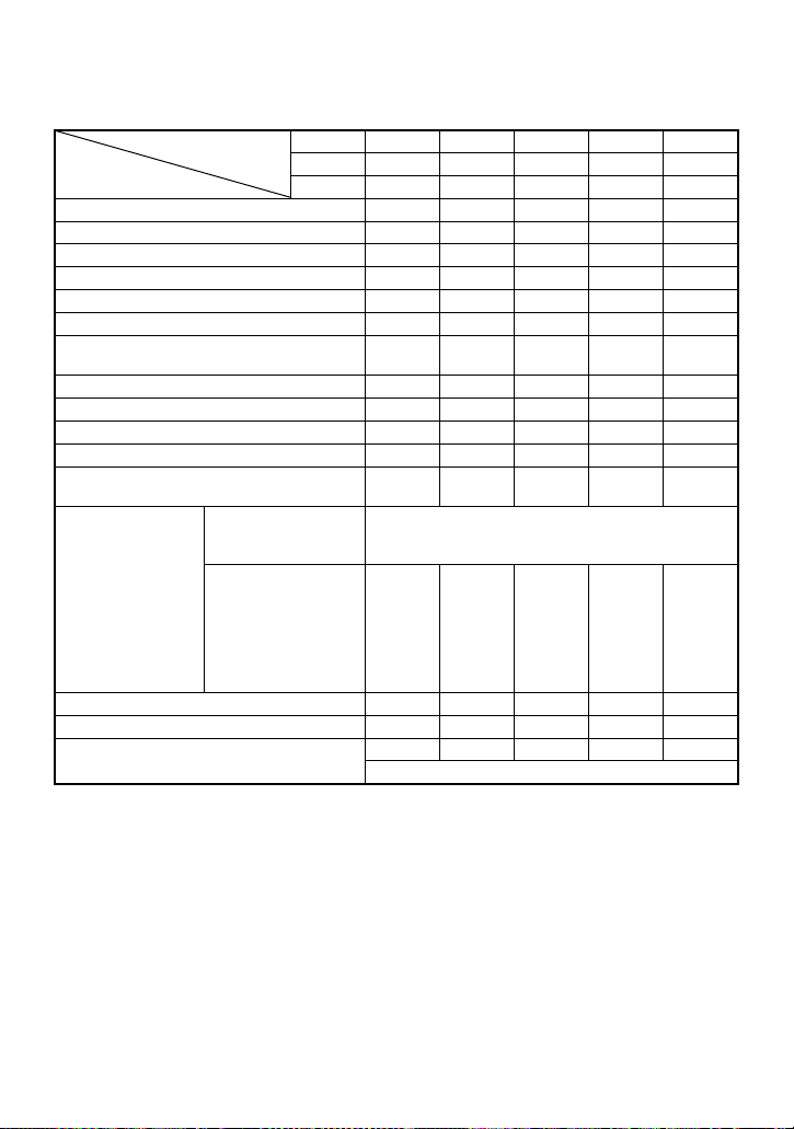
MAINTENANCE CHART
Interval: This interval should be judged by number of months or odometer reading, whichever comes first.
Intervalmonths2 12243648
km 1000 6000 12000 18000 24000
Element miles 600 4000 7500 11000 14500
Air cleaner element ( 7-10) – I I R I
* Exhaust pipe bolts and muffler bolts T – T – T
* Exhaust control valve I – I – I
*Valve clearance –––– I
Spark plugs ( 7-14) – I R I R
Fuel hose ( 7-27) – I I I I
* Evaporative emission control system
(California model only)
Engine oil ( 7-20) RRRRR
Engine oil filter ( 7-20) R – – R –
Throttle cable play ( 7-26) I I I I I
* PAIR (air supply) system – – I – I
* Throttle valve synchronization
“SUZUKI SUPER
LONG LIFE
COOLANT” (Blue)
* Engine coolant
( 7-28)
Radiator hose ( 7-30) –IIII
Clutch cable play ( 7-28) –IIII
Drive chain ( 7-30)
“SUZUKI LONG
LIFE COOLANT”
(Green) or an
engine coolant other
than “SUZUKI
SUPER LONG LIFE
COOLANT” (Blue)
–– I–I
I
(CA. only)
Replace every 4 years or 48000 km (29000 miles)
––R–R
IIIII
Clean and lubricate every 1000 km (600 miles)
–I–I
7-4
Page 84
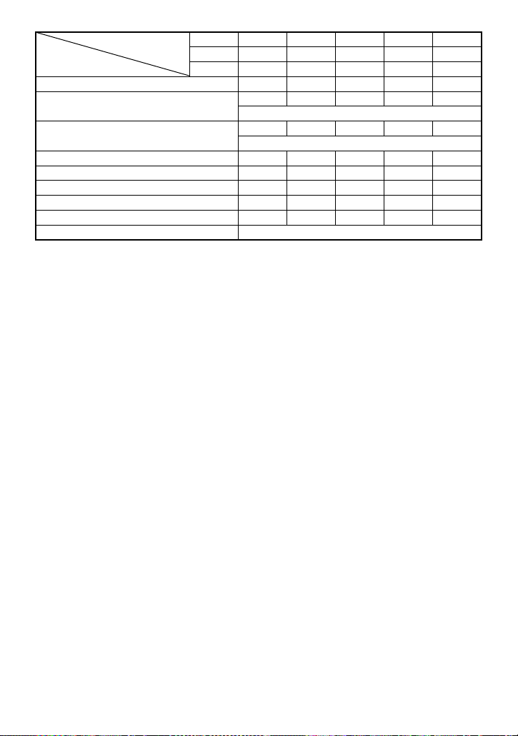
Intervalmonths2 12243648
km 1000 6000 12000 18000 24000
Element miles 600 4000 7500 11000 14500
*Brakes ( 7-34) IIIII
Brake hose ( 7-34)
Brake fluid ( 7-35)
Tires ( 7-39) – I I I I
*Steering I–I–I
* Front forks ( 3-34) – – I – I
* Rear suspension ( 3-35) – – I – I
*Chassis bolts and nuts TTTTT
Lubrication ( 7-7) Lubricate every 1000 km (600 miles)
–IIII
*Replace every 4 years
–IIII
*Replace every 2 years
NOTE: I= Inspect and clean, adjust, replace or lubricate as necessary;
R= Replace; T= Tighten
NOTE: (California model only) and (CA. only) means that the items or
the maintenance interval is to be applied only for the California model.
7-5
Page 85
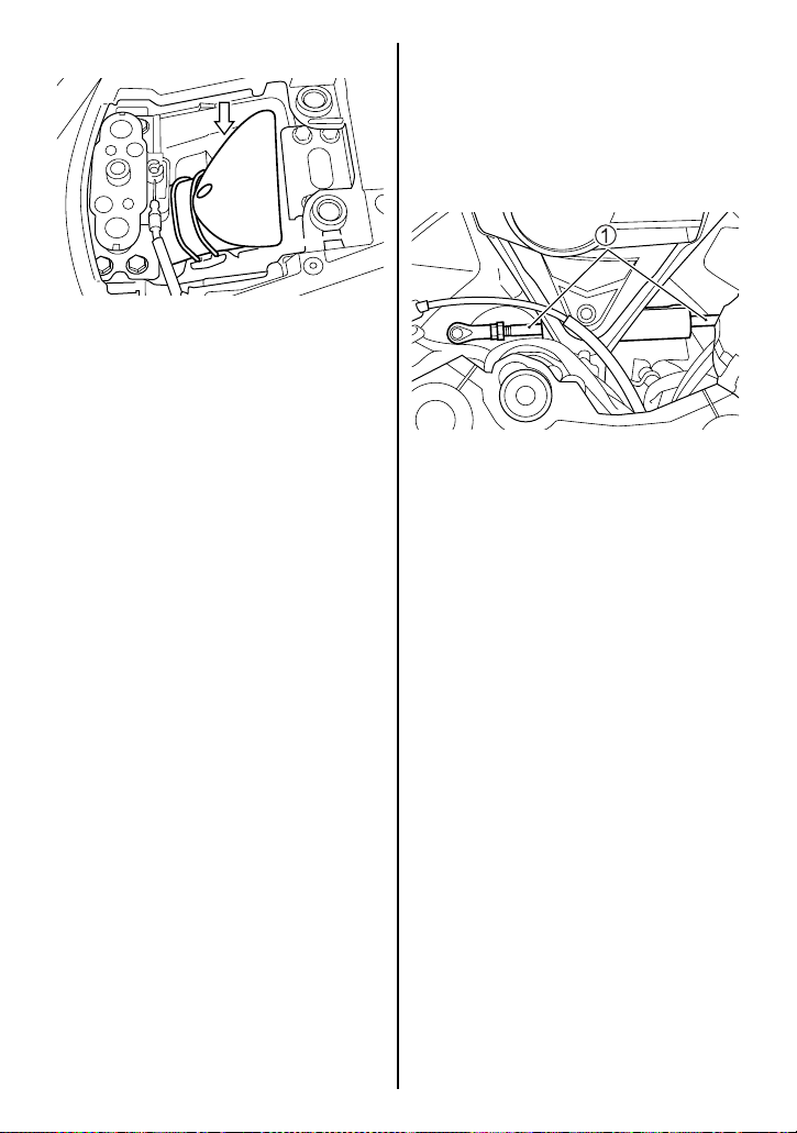
TOOLS
A tool kit is provided with your
motorcycle. It is located under the
rear seat.
STEERING DAMPER MAINTENANCE
1. Keep the steering damper
shaft 1 clean at all times.
2. Wipe off any oil residue with a
cloth.
NOTE:
• Do not confuse the grease-like
residue on the steering
damper’s shaft with an oil leak.
Collection of this residue is
normal and is from oil seal
lubricant used in the damper.
• You may also notice a sound
as the damper shaft is stroked
in and out. This “escaping air”
type sound is normal and is
made as the internal valving
damps the shaft movement.
7-6
Page 86
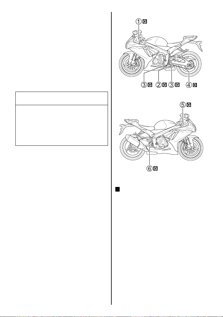
LUBRICATION POINTS
Proper lubrication is important for
smooth operation and long life of
each working part of your motorcycle and also for safe riding. It is
a good practice to lubricate the
motorcycle after a long rough ride
and after getting it wet it in the
rain or after washing it. Major
lubrication points are indicated
below.
NOTICE
Lubricating electrical switches
can damage the switches.
Do not apply grease or oil to
electrical switches.
.... Grease
D
.... Drive chain lubricant
1.... Clutch lever pivot
2.... Side stand pivot and
spring hook
3.... Gearshift lever pivot and
footrest pivot
4.... Drive chain
5.... Brake lever pivot
6.... Brake pedal pivot and
footrest pivot
7-7
Page 87
BATTERY
The battery is a sealed type battery and requires no maintenance. Have your dealer check
the battery’s state of charge periodically.
NOTE:
• For charging a sealed type
battery, use a battery charger
applicable to a sealed type
battery.
• If you cannot charge the battery, consult your authorized
Suzuki dealer.
WARNING
Battery posts, terminals, and
related accessories contain lead
and lead compounds. Lead is
harmful to your health if it gets
into your blood stream.
WARNING
Batteries produce flammable
hydrogen gas which can
explode if exposed to flames or
sparks.
Keep flames and sparks away
from the battery. Never smoke
when working near the battery.
WARNING
Wiping the battery with a dry
cloth can cause a static electricity spark, which can start a
fire.
Wipe the battery with a damp
cloth to avoid static electricity
build up.
Wash hands after handling any
parts containing lead.
WARNING
Diluted sulfuric acid from the
battery can cause blindness or
severe burns.
When working near the battery,
use proper eye protection and
gloves. Flush eyes or body
with ample water and get medical care immediately if you suffer injury. Keep batteries out of
reach of children.
NOTICE
Exceeding the maximum
charging rate for the battery
can shorten its life.
Never exceed the maximum
charging rate for the battery.
7-8
Page 88
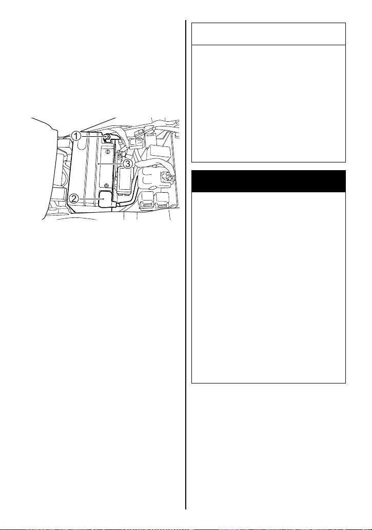
Battery Removal
To remove the battery, follow the
procedure below:
1. Place the motorcycle on the
side stand.
2. Remove the front seat by referring to the SEAT LOCK AND
HELMET HOLDERS section.
3. Disconnect the negative (–)
terminal 1.
4. Remove the cap. Disconnect
the positive (+) terminal 2.
5. Remove the battery 3.
To install the battery:
1. Install the battery in the
reverse order of removal.
2. Connect the battery terminals
securely.
NOTE: Be sure to reset the
engine rpm indicator in the instrument panel when the battery terminals are reconnected.
NOTICE
Reversing the battery lead
wires can damage the charging
system and the battery.
Always attach the red lead to
the (+) positive terminal and the
black (or black with white
tracer) lead to the (–) negative
terminal.
WARNING
Batteries contain toxic substances including sulfuric acid
and lead. They could cause
injury to humans or could damage the environment.
A used battery must be disposed of or recycled according
to local law and must not be
discarded with ordinary household waste. Make sure not to
tip over the battery when you
remove it from the vehicle. Otherwise, sulfuric acid could run
out and you might be injured.
NOTE:
• Select the same type MF battery when replacing the battery.
• Recharge the battery once a
month if the motorcycle is not
used for a long time.
7-9
Page 89
Pb
The crossed-out wheeled bin
symbol A located on the battery
label indicates that a used battery
should be collected separately
from ordinary household waste.
The chemical symbol of “Pb” B
indicates the battery contains
more than 0.004% lead.
By ensuring the used battery is
disposed of or recycled correctly,
you will help prevent potential
negative consequences for the
environment and human health,
which could otherwise be caused
by inappropriate waste handling
of the battery. The recycling of
materials will help to conserve
natural resources. For more
detailed information about disposing or recycling of the used battery, consult your Suzuki dealer.
AIR CLEANER
The air cleaner element must be
kept clean to provide good engine
power and gas mileage. If you use
your motorcycle under normal
low-stress conditions, you should
service the air cleaner at the intervals specified. If you ride in dusty,
wet, or muddy conditions, you will
need to inspect the air cleaner
element much more frequently.
Use the following procedure to
remove the element and inspect
it.
WARNING
Operating the engine without
the air cleaner element in place
can be hazardous. A flame can
spit back from the engine to
the air intake box without the
air cleaner element to stop it.
Severe engine damage can
also occur if dirt enters the
engine due to running the
engine without the air cleaner
element.
Never run the engine without
the air cleaner element in
place.
7-10
Page 90
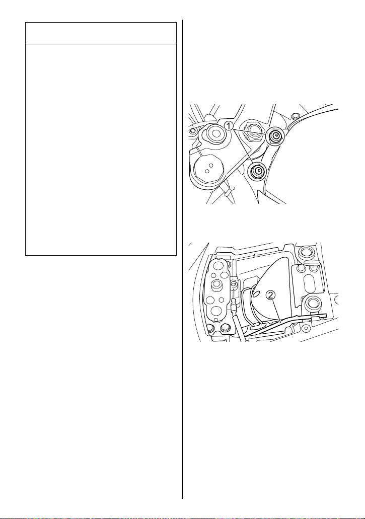
NOTICE
Failure to inspect the air
cleaner element frequently if
the vehicle is used in dusty,
wet, or muddy conditions can
damage your motorcycle. The
air cleaner element can
become clogged under these
conditions, and engine damage
may result.
Always inspect the air cleaner
element after riding in severe
conditions. Replace the element as necessary. If water
gets in the air cleaner case,
immediately clean the element
and the inside of the case.
Air Cleaner Element Removal
1. Place the motorcycle on the
side stand.
2. Remove the front and rear
seat by referring to the SEAT
LOCK AND HELMET HOLDERS section.
3. Remove the fuel tank fitting
bolts 1.
4. Remove the prop stay 2 if the
prop stay is equipped.
NOTE: A prop stay is available at
your Suzuki dealer. The prop stay
part number is 44574-35F00.
7-11
Page 91
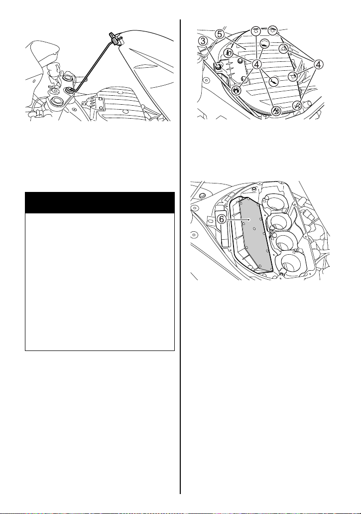
5. Lift the front end of the fuel
tank and prop it up as shown
above. Insert the crank end of
the prop stay into the hole of
the steering shaft.
WARNING
If you lift up the fuel tank when
it is full, fuel can seep out from
the fuel tank cap, creating a fire
hazard.
Reduce the fuel level to less
than 1/4 full before lifting up
the fuel tank. The fuel indicator
on the instrument panel will
blink or remain lit when the fuel
level is less than 1/4 full.
6. Remove the air cleaner holder
bolt 3.
7. Remove the 10 screws 4.
8. Remove the cover 5.
9. Remove the air cleaner ele-
ment 6.
7-12
Page 92
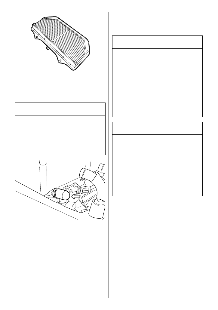
Installation
Reinstall the air cleaner element
in reverse order of removal.
NOTICE
A torn air cleaner element will
allow dirt to enter the engine
and can damage the engine.
10.Inspect the air cleaner element
condition. Replace the air
cleaner element periodically.
NOTICE
Compressed air can damage
the air cleaner element.
Do not blow the air cleaner element with compressed air.
11.Remove the plug and drain
water and oil at the periodic
maintenance interval. The air
cleaner drain plug is located
beneath the air cleaner box.
Replace the air cleaner element
with a new one if it is torn.
Carefully examine the air
cleaner element for tears during cleaning.
NOTICE
Failure to position the air
cleaner element properly can
allow dirt to bypass the air
cleaner element. This will
cause engine damage.
Be sure to properly install the
air cleaner element.
NOTE: Be careful not to spray
water on the air cleaner box when
cleaning the motorcycle.
Reinstall the fuel tank.
NOTE: Check that the fuel tank
drain hose and breather hose are
not bent before reinstalling the
fuel tank.
7-13
Page 93
SPARK PLUGS
Your motorcycle comes equipped
with an NGK CR9EIA-9 or
DENSO IU27D spark plugs. To
determine if the standard spark
plug is right for your usage, check
the color of the plug’s porcelain
center electrode insulator after
motorcycle operation. A light
brown color indicates that the plug
is correct. A white or dark insulator indicates that the engine may
need adjustment, or another plug
type may be needed. Consult
your Suzuki dealer or a qualified
mechanic if your plug insulator is
not a light brown color.
NOTICE
An improper spark plug may
have an incorrect fit or inappropriate heat range for your
engine. This may cause severe
engine damage which may not
be covered under warranty.
Plug Replacement Guide
NGK DENSO REMARKS
If the standard
CR8EIA-9 IU24D
CR9EIA-9 IU27D Standard
CR10EIA-9 IU31D
plug is apt to get
wet, replace with
this plug.
If the standard
plug is apt to
overheat, replace
with this plug.
NOTE: If the above-named plugs
are not available, consult your
Suzuki dealer.
NOTE: This motorcycle uses a
resistor-type spark plug to avoid
jamming electronic parts.
Improper spark plug selection
may cause electronic interference with your motorcycle’s ignition system, resulting in
motorcycle performance problems. Use only the recommended
spark plugs.
Use one of the spark plugs
listed or their equivalent. Consult your Suzuki dealer if you
are not sure which spark plug
is correct for your type of
usage.
7-14
Page 94
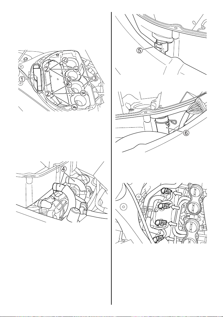
Spark Plug Removal
1. Lift the fuel tank and remove
the air cleaner cover by referring to the AIR CLEANER section.
2. Remove the ECM 1 from the
air cleaner box. Remove the
bolts 2 and two funnels 3.
Funnel bolt tightening torque:
43 N·m (4.3 kgf-m, 31.0 lbf-ft)
4. Disconnect the coupler 5.
5. Pull out the tube 6.
6. Remove the air cleaner box
and air cleaner inlet tubes.
3. Pull out the tubes 4.
7. Release the coupler locks and
disconnect the couplers from
the ignition coils.
7-15
Page 95
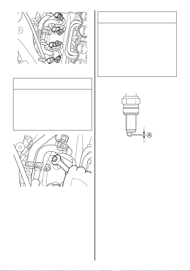
8. Pull off the ignition coils.
NOTICE
Dirt can damage the moving
engine parts of your motorcycle if it enters an open spark
plug hole.
Cover the spark plug hole
while the spark plug is out of
the hole.
NOTICE
Improper removal of ignition
coils can damage the ignition
coils.
Pull off the ignition coils with
your hand. Do not use pliers.
9. Remove the spark plugs with a
spark plug wrench.
Spark Plug Inspection
Measure the spark plug gap A
with a wire type feeler gauge. The
standard spark plug gap is 0.8 –
0.9 mm (0.031 – 0.035 in). If the
measured spark plug gap is out of
standard range, replace the spark
plug with a new one.
7-16
Page 96
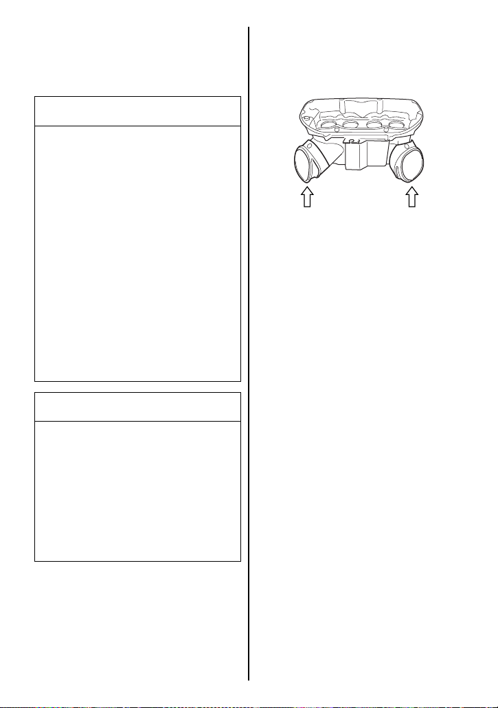
Installation
To install a spark plug, turn it in as
far as possible with your fingers,
then tighten it with a wrench.
NOTICE
Improper installation of the
spark plug can damage your
motorcycle. An overly-tight or
cross-threaded spark plug will
damage the aluminum threads
of the cylinder head.
Carefully turn the spark plug
by hand into the threads. If the
spark plug is new, tighten it
with a wrench about 1/2 turn
past finger tight. If you are
reusing the old spark plug,
tighten it with a wrench about
1/8 turn past finger tight.
NOTICE
Dirt can damage the moving
engine parts of your motorcycle if it enters an open spark
plug hole.
Reinstall the air cleaner box and
fuel tank in the reverse order of
removal.
NOTE: Be careful to check that
the inlet tubes are fitted securely
when reinstalling the air cleaner
box.
NOTE: Check that the fuel tank
drain hose and breather hose are
not bent before reinstalling the
fuel tank.
Cover the spark plug hole
while the spark plug is out of
the hole.
7-17
Page 97
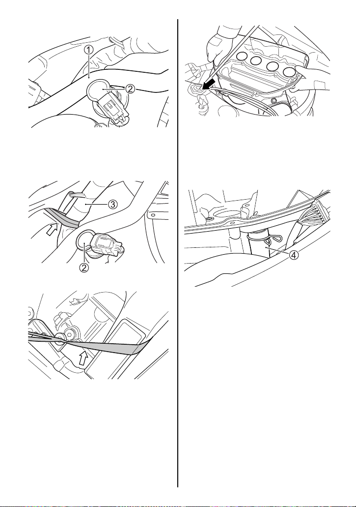
Air Cleaner Box Installation
1. Position the PAIR hose 1 by
the ignition coil 2 as shown
above.
3. Install the air cleaner box in
the following order. Fit the right
side air inlet tube to the frame
hole first, then fit the left side
inlet tube.
4. Fit the PAIR hose 4 to the air
cleaner box. Remove the
string from the harness.
5. Fit removed parts, e.g. air
cleaner cover, fuel tank, lead
wires, in the reverse order of
removal.
2. Pull the harness 3 ahead by a
string in order to avoid the harness 3 pushing the PAIR
hose on the ignition coil 2 as
shown above.
7-18
Page 98
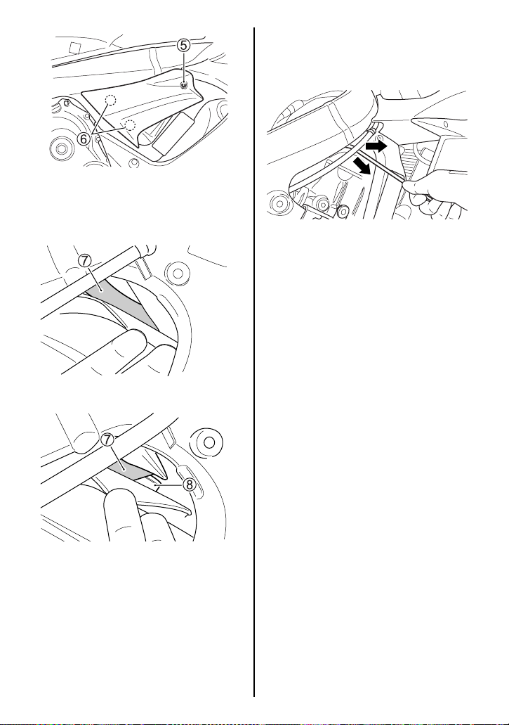
6. Remove the screw 5. Unhook
the bosses 6 and remove the
cover.
OK
NOTE: A prop stay is available at
your Suzuki dealer. The prop stay
part number is 44574-35F00.
8. Hook the PAIR hose by the
fuel tank prop stay and pull the
hose out to the front-right
direction. Check if the PAIR
hose became free from the
ignition coil.
9. Install the cover.
NG
7. Check if the PAIR hose routed
correctly. If the PAIR hose 7 is
pinched between the ignition
coil 8 and the air cleaner box,
pull out the PAIR hose by the
fuel tank prop stay in the procedure below.
7-19
Page 99
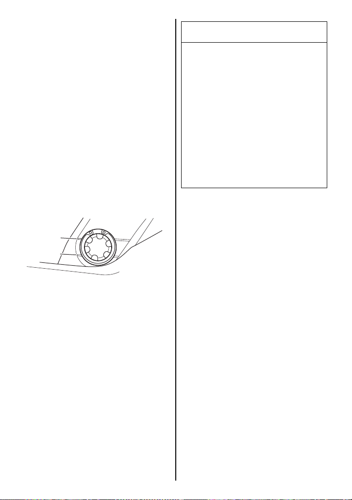
ENGINE OIL
Engine life depends on oil amount
and quality. Daily oil level checks
and periodic changes are two of
the most important maintenance
items to be performed.
NOTICE
Operating the motorcycle with
too little or too much oil can
damage the engine.
Engine Oil Level Check
Check the engine oil level as follows:
1. Place the motorcycle on level
ground on the side stand.
2. Start the engine and allow it to
idle for three minutes.
3. Stop the engine and wait three
minutes.
F
L
4. Hold the motorcycle vertically
and check the oil level through
the oil level inspection window
on the right side of the engine.
The engine oil level should be
between the “L” (low) and the
“F” (full) lines.
Place the motorcycle on level
ground. Check the oil level with
the engine oil inspection window before each use of the
vehicle. Be sure the engine oil
level is always above the “L”
(low) line and not higher than
the “F” (full) line.
7-20
Page 100
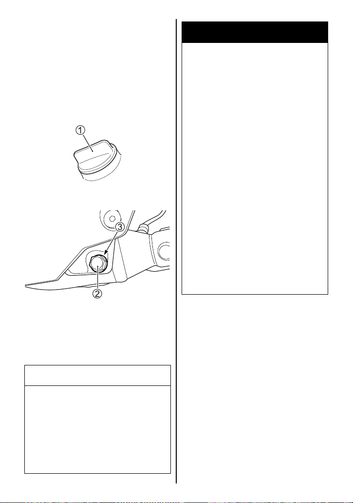
Engine Oil and Filter Change
Change the engine oil and oil filter
at the scheduled times. The
engine should always be warm
when the oil is changed so the oil
will drain easily. The procedure is
as follows:
1. Place the motorcycle on the
side stand.
2. Remove the oil filler cap 1.
WARNING
Children and pets may be
harmed by swallowing new or
used oil. Repeated, prolonged
contact with used engine oil
may cause skin cancer. Brief
contact with oil may irritate
skin.
Keep new and used oil and
used oil filters away from children and pets. To minimize
your exposure to used oil, wear
a long-sleeve shirt and moisture-proof gloves (such as
dishwashing gloves) when
changing oil. If oil contacts
your skin, wash thoroughly
with soap and water. Launder
any clothing or rags if wet with
oil. Recycle or properly dispose of used oil and filters.
3. Remove the drain plug 2 and
gasket 3 from the bottom of
the engine and drain the
engine oil into a drain pan.
CAUTION
Hot engine oil and exhaust
pipes can burn you.
Wait until the oil drain plug and
exhaust pipes are cool enough
to touch with bare hands
before draining oil.
7-21
 Loading...