

Page 1
GSX-R600
99500-35100-01E
Page 2
FOREWORD
This manual contains an introductory description on
the SUZUKI GSX-R600 and procedures for its
inspection/service and overhaul of its main components.
Other information considered as generally known is
not included.
Read the GENERAL INFORMATION section to
familiarize yourself with the motorcycle and its maintenance. Use this section as well as other sections
to use as a guide for proper inspection and service.
This manual will help you know the motorcycle better so that you can assure your customers of fast
and reliable service.
* This manual has been prepared on the basis
of the latest specifications at the time of publication. If modifications have been made since
then, differences may exist between the content of this manual and the actual motorcycle.
* Illustrations in this manual are used to show
the basic principles of operation and work
procedures. They may not represent the
actual motorcycle exactly in detail.
* This manual is written for persons who have
enough knowledge, skills and tools, including
special tools, for servicing SUZUKI motorcycles. If you do not have the proper knowledge
and tools, ask your authorized SUZUKI
motorcycle dealer to help you.
GROUP INDEX
GENERAL INFORMATION
PERIODIC MAINTENANCE
ENGINE
FI SYSTEM DIAGNOSIS
FUEL SYSTEM AND THROTTLE
BODY
EXHAUST SYSTEM
COOLING AND LUBRICATION
SYSTEM
CHASSIS
1
2
3
4
5
6
7
8
Inexperienced mechanics or mechanics
without the proper tools and equipment
may not be able to properly perform the
services described in this manual.
Improper repair may result in injury to the
mechanic and may render the motorcycle
unsafe for the rider and passenger.
© COPYRIGHT SUZUKI MOTOR CORPORATION 2006
ELECTRICAL SYSTEM
SERVICING INFORMATION
EMISSION CONTROL
INFORMATION
WIRING DIAGRAM
9
10
11
12
Page 3
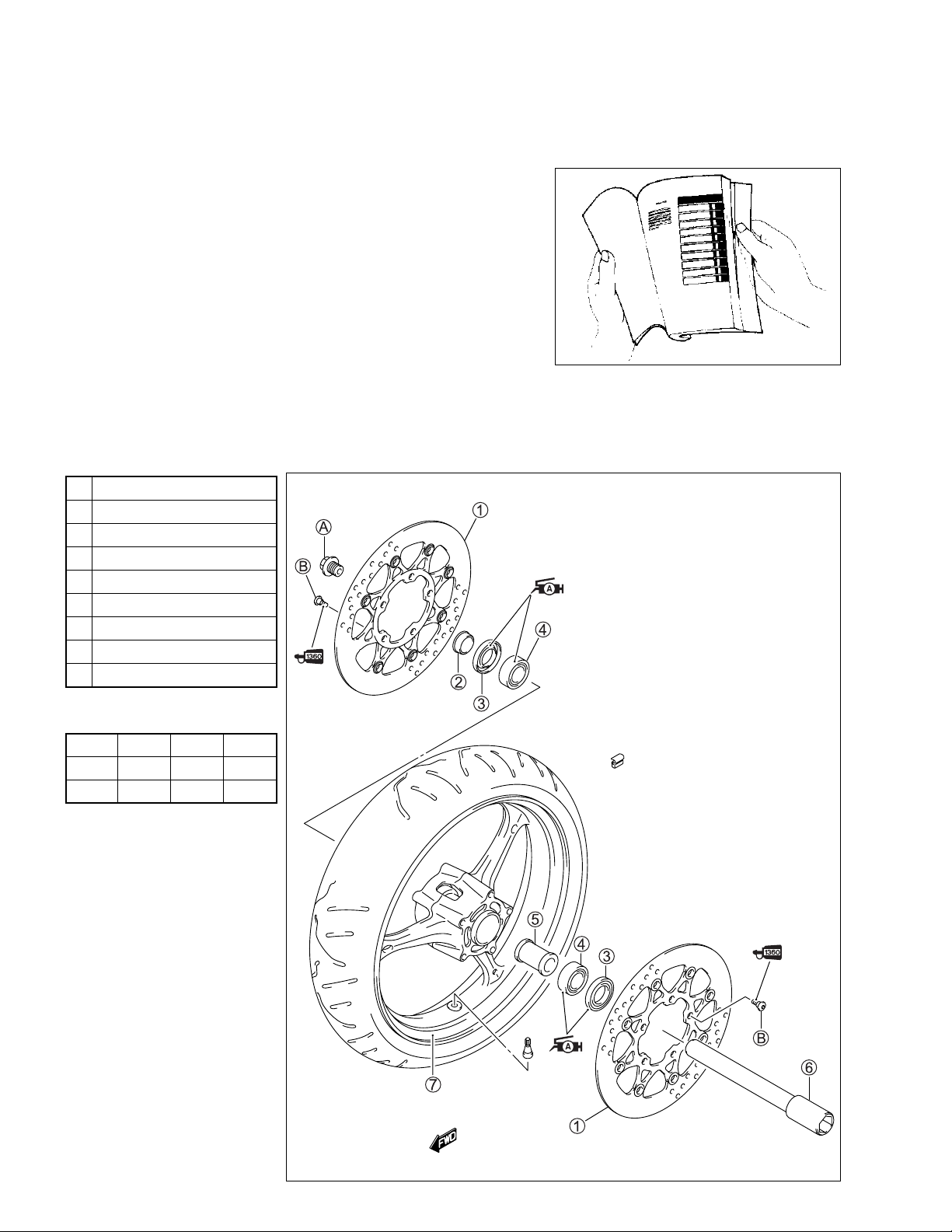
HOW TO USE THIS MANUAL
TO LOCATE WHAT YOU ARE LOOKING FOR:
1. The text of this manual is divided into sections.
2. The section titles are listed in the GROUP INDEX.
3. Holding the manual as shown at the right will allow you to find
the first page of the section easily.
4. The contents are listed on the first page of each section to
help you find the item and page you need.
COMPONENT PARTS AND WORK TO BE DONE
Under the name of each system or unit, is its exploded view. Work instructions and other service information
such as the tightening torque, lubricating points and locking agent points, are provided.
Example: Front wheel
1 Brake disc
2 Collar
3 Dust seal
4 Bearing
5 Spacer
6 Front axle
7 Front wheel
A Front axle bolt
B Brake disc bolt
ITEM N·m
A 100 10.0 72.5
B 23 2.3 16.5
kgf-m
lb-ft
Page 4
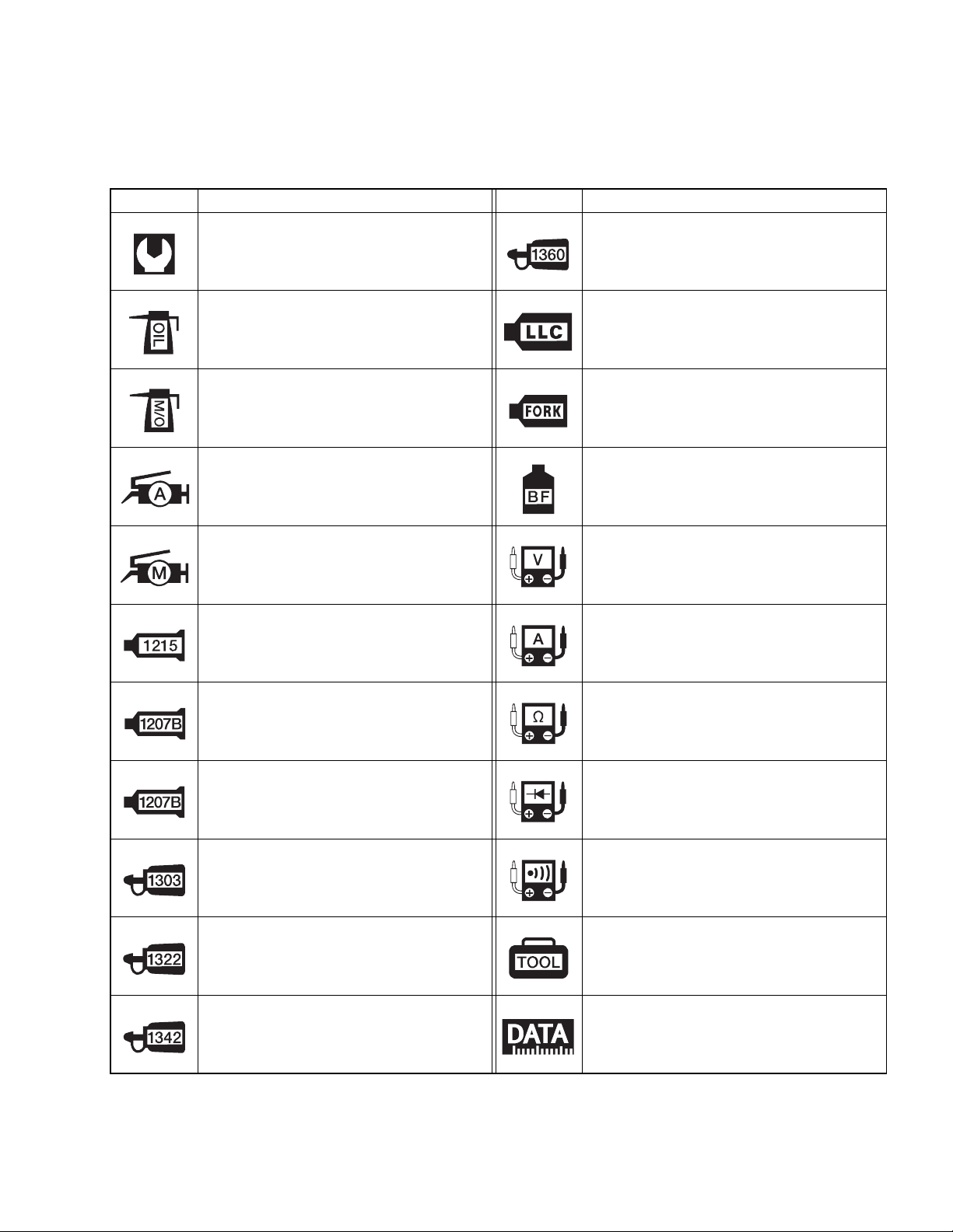
SYMBOL
Listed in the table below are the symbols indicating instructions and other information necessary for servicing. The meaning of each symbol is also included in the table.
SYMBOL DEFINITION SYMBOL DEFINITION
Torque control required.
Data beside it indicates specified
torque.
Apply oil. Use engine oil unless otherwise specified.
Apply molybdenum oil solution.
(Mixture of engine oil and SUZUKI
MOLY PASTE in a ratio of 1:1)
Apply SUZUKI SUPER GREASE “A”
or equivalent grease.
99000-25010
Apply SUZUKI MOLY PASTE.
99000-25140
Apply SUZUKI BOND “1215”
or equivalent bond.
99000-31110
Apply THREAD LOCK SUPER “1360”.
99000-32130
Use engine coolant.
99000-99032-11X (Except USA)
Use fork oil.
99000-99001-SS5
Apply or use brake fluid.
Measure in voltage range.
Measure in current range.
Apply SUZUKI BOND “1207B”.
99104-31140 (USA)
Apply SUZUKI BOND “1207B”.
99000-31140 (Except USA)
Apply THREAD LOCK SUPER “1303”.
99000-32030
Apply THREAD LOCK SUPER “1322”
or equivalent thread lock.
99000-32110
Apply THREAD LOCK “1342”.
99000-32050
Measure in resistance range.
Measure in diode test range.
Measure in continuity test range.
Use special tool.
Indication of service data.
Page 5

ABBREVIATIONS USED IN THIS MANUAL
A
ABDC : After Bottom Dead Center
AC : Alternating Current
ACL : Air Cleaner, Air Cleaner Box
API : American Petroleum Institute
ATDC : After Top Dead Center
ATM Pressure
A/F : Air Fuel Mixture
: Atmospheric Pressure
: Atmospheric Pressure sensor
(APS, AP Sensor)
B
BBDC : Before Bottom Dead Center
BTDC : Before Top Dead Center
B+ : Battery Positive Voltage
C
CKP Sensor : Crankshaft Position Sensor
(CKPS)
CKT : Circuit
CLP Switch : Clutch Lever Position Switch
(Clutch Switch)
CMP Sensor : Camshaft Position Sensor
(CMPS)
CO : Carbon Monoxide
CPU : Central Processing Unit
D
DC : Direct Current
DMC : Dealer Mode Coupler
DOHC : Double Over Head Camshaft
DRL : Daytime Running Light
DTC : Diagnostic Trouble Code
E
ECM : Engine Control Module
Engine Control Unit (ECU)
(FI Control Unit)
ECT Sensor : Engine Coolant Temperature
Sensor (ECTS), Water Temp.
Sensor (WTS)
EVAP : Evaporative Emission
EVAP Canister : Evaporative Emission
Canister (Canister)
EXC System : Exhaust Control System (EXCS)
EXC Valve : Exhaust Control Valve (EXCV)
EXCV Actuator
: Exhaust Control Valve Actuator
(EXCVA)
F
FI : Fuel Injection, Fuel Injector
FP : Fuel Pump
FPR : Fuel Pressure Regulator
FP Relay : Fuel Pump Relay
G
GEN : Generator
GND : Ground
GP Switch : Gear Position Switch
H
HC : Hydrocarbons
I
IAP Sensor : Intake Air Pressure Sensor (IAPS)
(MAP Sensor)
IAT Sensor : Intake Air Temperature Sensor
(IATS)
IG : Ignition
L
LCD : Liquid Crystal Display
LED : Light Emitting Diode
(Malfunction Indicator Lamp)
LH : Left Hand
Page 6

M
MAL-Code : Malfunction Code
(Diagnostic Code)
Max : Maximum
MIL : Malfunction Indicator Lamp
(LED)
Min : Minimum
N
NOX : Nitrogen Oxides
O
OHC : Over Head Camshaft
OPS : Oil Pressure Switch
P
PCV : Positive Crankcase
Ventilation (Crankcase Breather)
R
RH : Right Hand
ROM : Read Only Memory
S
SAE : Society of Automotive Engineers
SDS : Suzuki Diagnosis System
STC System : Secondary Throttle Control System
(STCS)
STP Sensor : Secondary Throttle Position Sensor
(STPS)
ST Valve : Secondary Throttle Valve (STV)
STV Actuator : Secondary Throttle Valve Actuator
(STVA)
T
TO Sensor : Tip-Over Sensor (TOS)
TP Sensor : Throttle Position Sensor (TPS)
Page 7

WIRE COLOR
B : Black G : Green P :Pink
Bl : Blue Gr : Gray R : Red
Br : Brown Lbl : Light blue W : White
Dg : Dark green Lg : Light green Y : Yellow
Dgr : Dark gray O : Orange
B/Bl : Black with Blue tracer B/Br : Black with Brown tracer
B/G : Black with Green tracer B/Lg : Black with Light green tracer
B/R : Black with Red tracer B/W : Black with White tracer
B/Y : Black with Yellow tracer Bl/B : Blue with Black tracer
Bl/G : Blue with Green tracer Bl/R : Blue with Red tracer
Bl/W : Blue with White tracer Bl/Y : Blue with Yellow tracer
Br/Y : Brown with Yellow tracer G/B : Green with Black tracer
G/Bl : Green with Blue tracer G/R : Green with Red tracer
G/W : Green with White tracer G/Y : Green with Yellow tracer
Gr/B : Gray with Black tracer Gr/R : Gray with Red tracer
Gr/W : Gray with White tracer Gr/Y : Gray with Yellow tracer
Lg/BI : Light green with Blue tracer Lg/G : Light green with Green tracer
Lg/W : Light green with White tracer O/B : Orange with Black tracer
O/BI : Orange with Blue tracer O/G : Orange with Green tracer
O/R : Orange with Red tracer O/W : Orange with White tracer
O/Y : Orange with Yellow tracer P/B : Pink with Black tracer
P/W : Pink with White tracer R/B : Red with Black tracer
R/Bl : Red with Blue tracer R/Y : Red with Yellow tracer
R/W : Red with White tracer W/B : White with Black tracer
W/Bl : White with Blue tracer W/G : White with Green tracer
W/R : White with Red tracer W/Y : White with Yellow tracer
Y/B : Yellow with Black tracer Y/Bl : Yellow with Blue tracer
Y/G : Yellow with Green tracer Y/R : Yellow with Red tracer
Y/W : Yellow with White tracer
Page 8
GENERAL INFORMATION 1-1
GENERAL INFORMATION
CONTENTS
WARNING/CAUTION/NOTE......................................................................... 1- 2
GENERAL PRECAUTIONS .......................................................................... 1- 2
SUZUKI GSX-R600K6 (’06-MODEL)............................................................ 1- 4
SERIAL NUMBER LOCATION ..................................................................... 1- 4
FUEL, OIL AND ENGINE COOLANT RECOMMENDATION....................... 1- 5
FUEL (FOR USA AND CANADA).......................................................... 1- 5
FUEL (FOR OTHER COUNTRIES) ........................................................ 1- 5
ENGINE OIL (FOR USA)........................................................................ 1- 5
ENGINE OIL (FOR OTHER COUNTRIES)............................................. 1- 5
BRAKE FLUID........................................................................................ 1- 5
FRONT FORK OIL.................................................................................. 1- 6
ENGINE COOLANT................................................................................ 1- 6
WATER FOR MIXING............................................................................. 1- 6
ANTI-FREEZE/ENGINE COOLANT....................................................... 1- 6
LIQUID AMOUNT OF WATER/ENGINE COOLANT ............................. 1- 6
BREAK-IN PROCEDURES........................................................................... 1- 7
CYLINDER IDENTIFICATION....................................................................... 1- 7
INFORMATION LABELS .............................................................................. 1- 8
SPECIFICATIONS......................................................................................... 1- 9
DIMENSIONS AND DRY MASS............................................................. 1- 9
ENGINE .................................................................................................. 1- 9
DRIVE TRAIN ......................................................................................... 1- 9
CHASSIS ................................................................................................ 1-10
ELECTRICAL ......................................................................................... 1-10
CAPACITIES .......................................................................................... 1-10
1
COUNTRY AND AREA CODES
The following codes stand for the applicable country(-ies) and area(-s).
CODE COUNTRY or AREA EFFECTIVE FRAME NO.
E-02
E-19 (GSX-R600)
E-19 (GSX-R600U2)
E-19 (GSX-R600U3)
E-24
E-03
E-28
E-33
U.K.
E.U.
E.U.
E.U.
Australia
U.S.A. (Except for California)
Canada
California (U.S.A.)
JS1CE111100100001 –
JS1CE111100100001 –
JS1CE211100100001 –
JS1CE311100100001 –
JS1CE121300100001 –
JS1GN7DA 62100001 –
JS1GN7DA 62100001 –
JS1GN7DA 62100001 –
Page 9

1-2 GENERAL INFORMATION
WARNING/CAUTION/NOTE
Please read this manual and follow its instructions carefully. To emphasize special information, the symbol
and the words WARNING, CAUTION and NOTE have special meanings. Pay special attention to the messages highlighted by these signal words.
Indicates a potential hazard that could result in death or injury.
Indicates a potential hazard that could result in motorcycle damage.
NOTE:
Indicates special information to make maintenance easier or instructions clearer.
Please note, however, that the warnings and cautions contained in this manual cannot possibly cover all
potential hazards relating to the servicing, or lack of servicing, of the motorcycle. In addition to the WARNINGS and CAUTIONS stated, you must use good judgement and basic mechanical safety principles. If you
are unsure about how to perform a particular service operation, ask a more experienced mechanic for
advice.
GENERAL PRECAUTIONS
* Proper service and repair procedures are important for the safety of the service mechanic and
the safety and reliability of the motorcycle.
* When 2 or more persons work together, pay attention to the safety of each other.
* When it is necessary to run the engine indoors, make sure that exhaust gas is forced out-
doors.
* When working with toxic or flammable materials, make sure that the area you work in is well-
ventilated and that you follow all of the material manufacturer’s instructions.
* Never use gasoline as a cleaning solvent.
* To avoid getting burned, do not touch the engine, engine oil, radiator and exhaust system
until they have cooled.
After servicing the fuel, oil, water, exhaust or brake systems, check all lines and fittings related
to the system for leaks.
Page 10

GENERAL INFORMATION 1-3
* If parts replacement is necessary, replace the parts with Suzuki Genuine Parts or their equiva-
lent.
* When removing parts that are to be reused, keep them arranged in an orderly manner so that
they may be reinstalled in the proper order and orientation.
* Be sure to use special tools when instructed.
* Make sure that all parts used in reassembly are clean. Lubricate them when specified.
* Use the specified lubricant, bond, or sealant.
* When removing the battery, disconnect the negative cable first and then the positive cable.
* When reconnecting the battery, connect the positive cable first and then the negative cable,
and replace the terminal cover on the positive terminal.
* When performing service to electrical parts, if the service procedures do not require use of
battery power, disconnect the negative cable from the battery.
* When tightening the cylinder head or case bolts and nuts, tighten the larger sizes first.
Always tighten the bolts and nuts diagonally from the inside toward outside and to the speci-
fied tightening torque.
* Whenever you remove oil seals, gaskets, packing, O-rings, locking washers, self-locking
nuts, cotter pins, circlips and certain other parts as specified, be sure to replace them with
new ones. Also, before installing these new parts, be sure to remove any left over material
from the mating surfaces.
* Never reuse a circlip. When installing a new circlip, take care not to expand the end gap larger
than required to slip the circlip over the shaft. After installing a circlip, always ensure that it is
completely seated in its groove and securely fitted.
* Use a torque wrench to tighten fasteners to the specified torque. Wipe off grease and oil if a
thread is smeared with them.
* After reassembling, check parts for tightness and proper operation.
* To protect the environment, do not unlawfully dispose of used motor oil, engine coolant and
other fluids: batteries and tires.
* To protect Earth’s natural resources, properly dispose of used motorcycle and parts.
Page 11
1-4 GENERAL INFORMATION
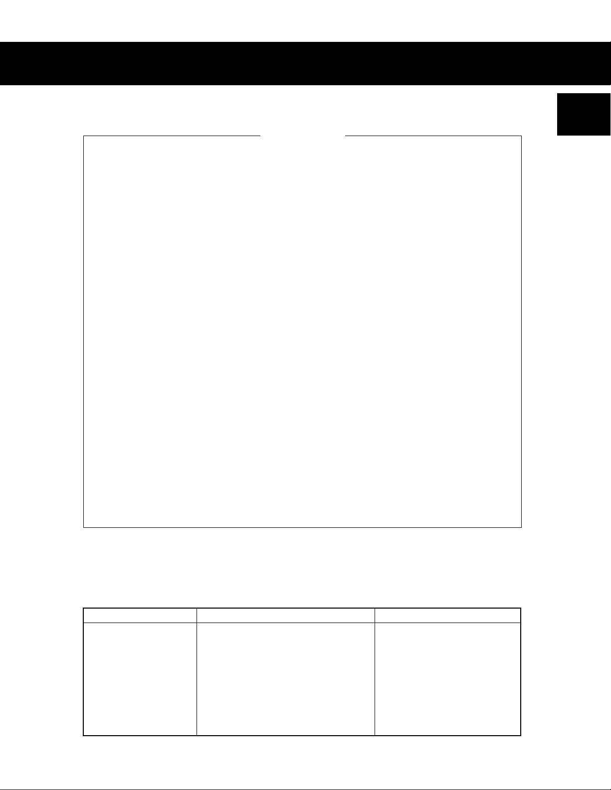
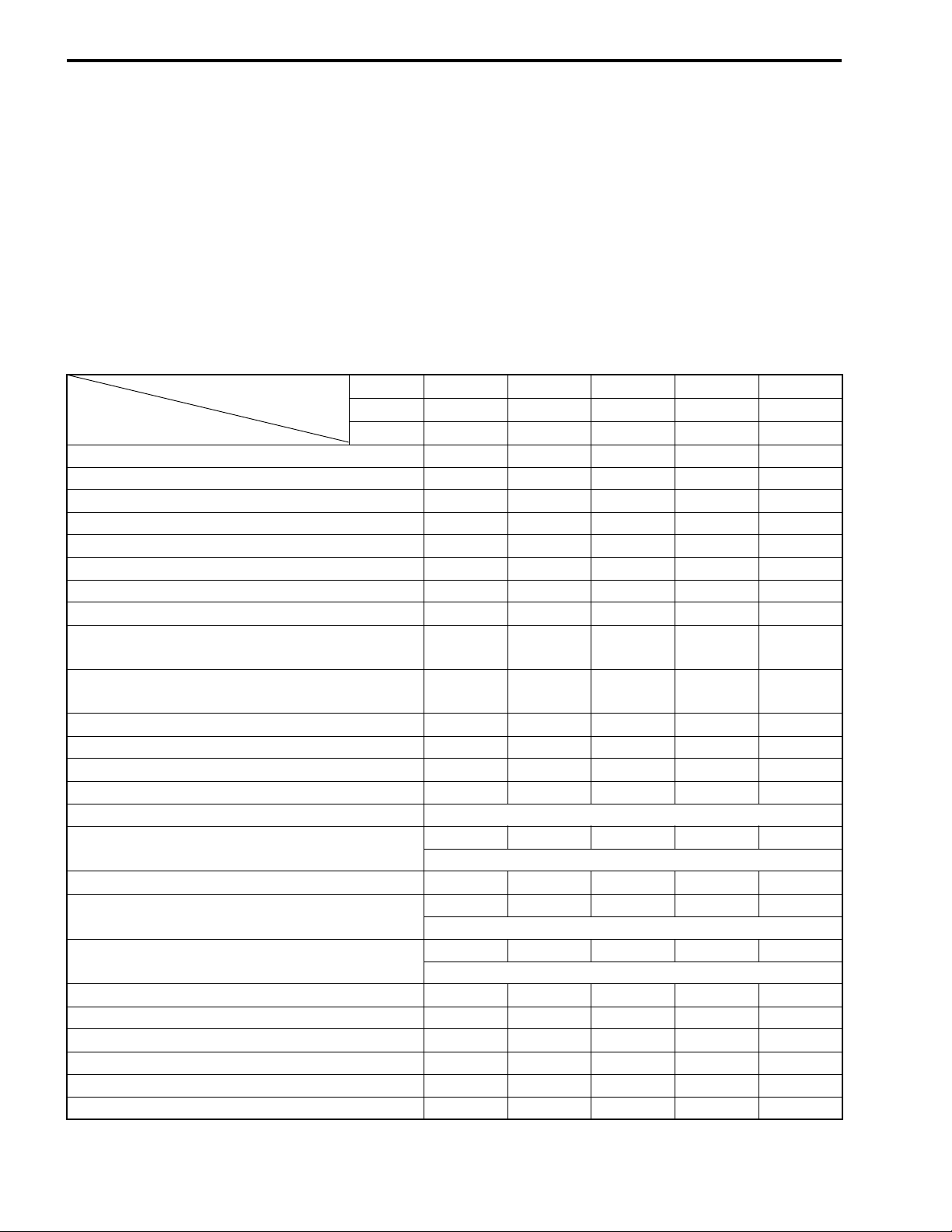
SUZUKI GSX-R600K6 (’06-MODEL)
RIGHT SIDE
LEFT SIDE
• Difference between illustrations and actual motorcycle may exist depending on the markets.
SERIAL NUMBER LOCATION
The frame serial number or V.I.N. (Vehicle Identification Number) 1 is stamped on the right side of the
steering head pipe. The engine serial number 2 is located on the right side of the crankcase. These numbers are required especially for registering the machine and ordering spare parts.
Page 12
GENERAL INFORMATION 1-5
FUEL, OIL AND ENGINE COOLANT RECOMMENDATION
FUEL (FOR USA AND CANADA)
Use only unleaded gasoline of at least 87 pump octane (R/2 + M/2) or 91 octane or higher rated by the
research method.
Gasoline containing MTBE (Methyl Tertiary Butyl Ether), less than 10% ethanol, or less than 5% methanol
with appropriate cosolvents and corrosion inhibitor is permissible.
FUEL (FOR OTHER COUNTRIES)
Gasoline used should be graded 91 octane (Research Method) or higher. Unleaded gasoline is recommended.
ENGINE OIL (FOR USA)
Oil quality is a major contributor to your engine’s performance and life. Always select good quality engine oil.
Suzuki recommends the use of SUZUKI PERFORMANCE 4 MOTOR OIL or equivalent engine oil. Use of
SF/SG or SH/SJ in API with MA in JASO.
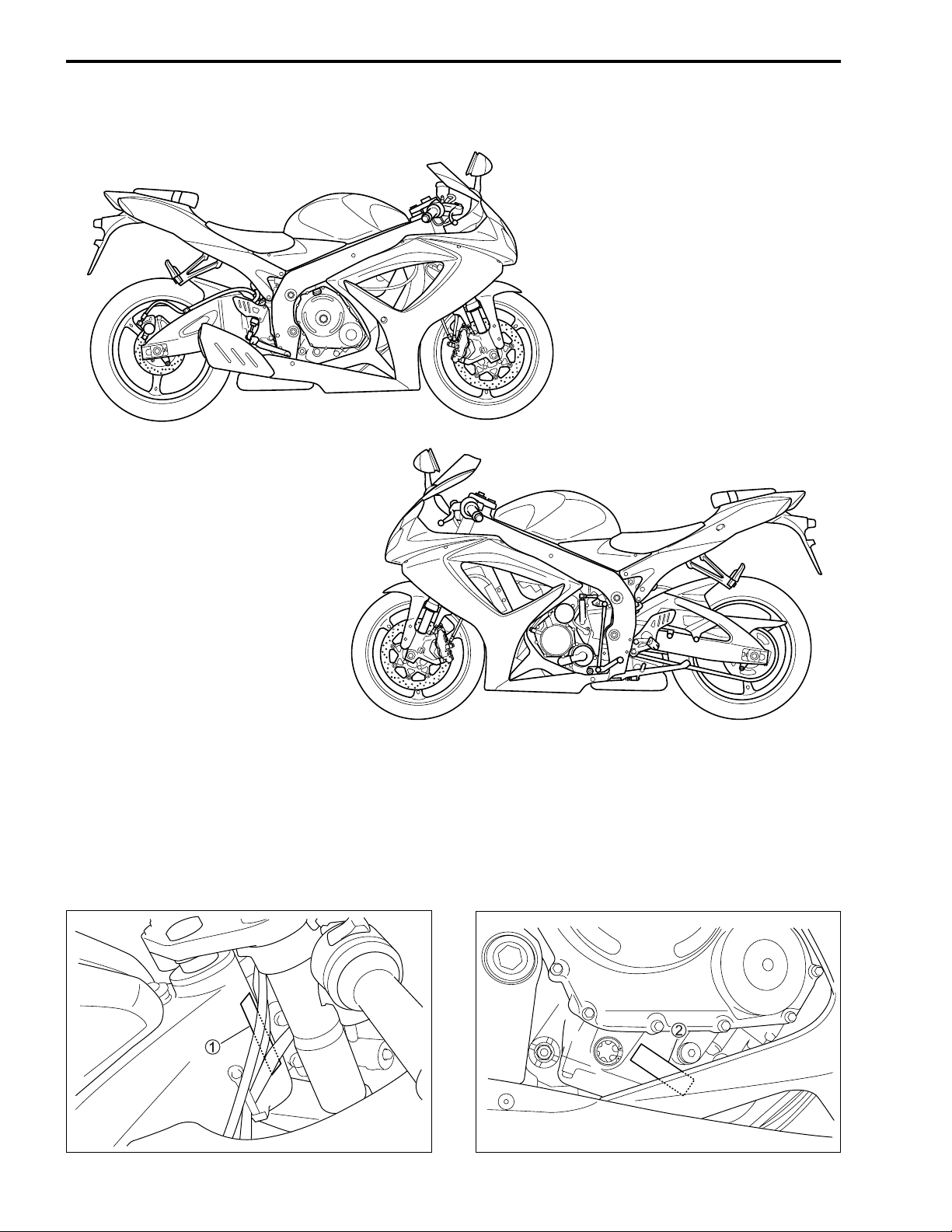
Suzuki recommends the use of SAE 10W-40 engine oil. If SAE 10W-40 engine oil is not available, select an
alternative according to the following chart.
ENGINE OIL (FOR OTHER COUNTRIES)
Oil quality is a major contributor to your engine’s performance
and life. Always select good quality engine oil. Use of SF/SG or
SH/SJ in API with MA in JASO.
Suzuki recommends the use of SAE 10W-40 engine oil. If SAE
10W-40 engine oil is not available, select an alternative according to the right chart.
BRAKE FLUID
Specification and classification: DOT 4
Since the brake system of this motorcycle is filled with a glycol-based brake fluid by the manufacturer, do not use or mix different types of fluid such as silicone-based and petroleum-based
fluid for refilling the system, otherwise serious damage will result.
Do not use any brake fluid taken from old or used or unsealed containers.
Never re-use brake fluid left over from a previous servicing, which has been stored for a long
period.
Page 13

1-6 GENERAL INFORMATION
FRONT FORK OIL
Use fork oil SS-05 or an equivalent fork oil.
ENGINE COOLANT
Use an anti-freeze/engine coolant compatible with an aluminum radiator, mixed with distilled water only.
WATER FOR MIXING
Use distilled water only. Water other than distilled water can corrode and clog the aluminum radiator.
ANTI-FREEZE/ENGINE COOLANT
The engine coolant performs as a corrosion and rust inhibitor as well as anti-freeze. Therefore, the engine
coolant should be used at all times even though the atmospheric temperature in your area does not go down
to freezing point.
Suzuki recommends the use of SUZUKI COOLANT anti-freeze/engine coolant. If this is not available, use
an equivalent which is compatible with an aluminum radiator.
LIQUID AMOUNT OF WATER/ENGINE COOLANT
Solution capacity (total): Approx. 2 700 ml (2.9/2.4 US/Imp qt)
For engine coolant mixture information, refer to cooling system section in page 7-2.
Mixing of anti-freeze/engine coolant should be limited to 60%. Mixing beyond it would reduce
its efficiency. If the anti-freeze/engine coolant mixing ratio is below 50%, rust inhabiting performance is greatly reduced. Be sure to mix it above 50% even though the atmospheric temperature does not go down to the freezing point.
Page 14
GENERAL INFORMATION 1-7
BREAK-IN PROCEDURES
During manufacture only the best possible materials are used and all machined parts are finished to a very
high standard but it is still necessary to allow the moving parts to “BREAK-IN” before subjecting the engine
to maximum stresses. The future performance and reliability of the engine depends on the care and restraint
exercised during its early life. The general rules are as follows.
• Keep to these break-in engine speed limits:
Initial 800 km ( 500 miles): Below 8 000 r/min
Up to 1 600 km (1 000 miles): Below 12 000 r/min
Over to 1 600 km (1 000 miles): Below 16 000 r/min
• Upon reaching an odometer reading of 1 600 km (1 000 miles) you can subject the motorcycle to full throttle operation.
However, do not exceed 16 000 r/min at any time.
CYLINDER IDENTIFICATION
The four cylinders of this engine are identified as No. 1, No. 2, No. 3 and No. 4 cylinder, as counted from left
to right (as viewed by the rider on the seat.)
#1
#2
#4
#3
Page 15
1-8 GENERAL INFORMATION
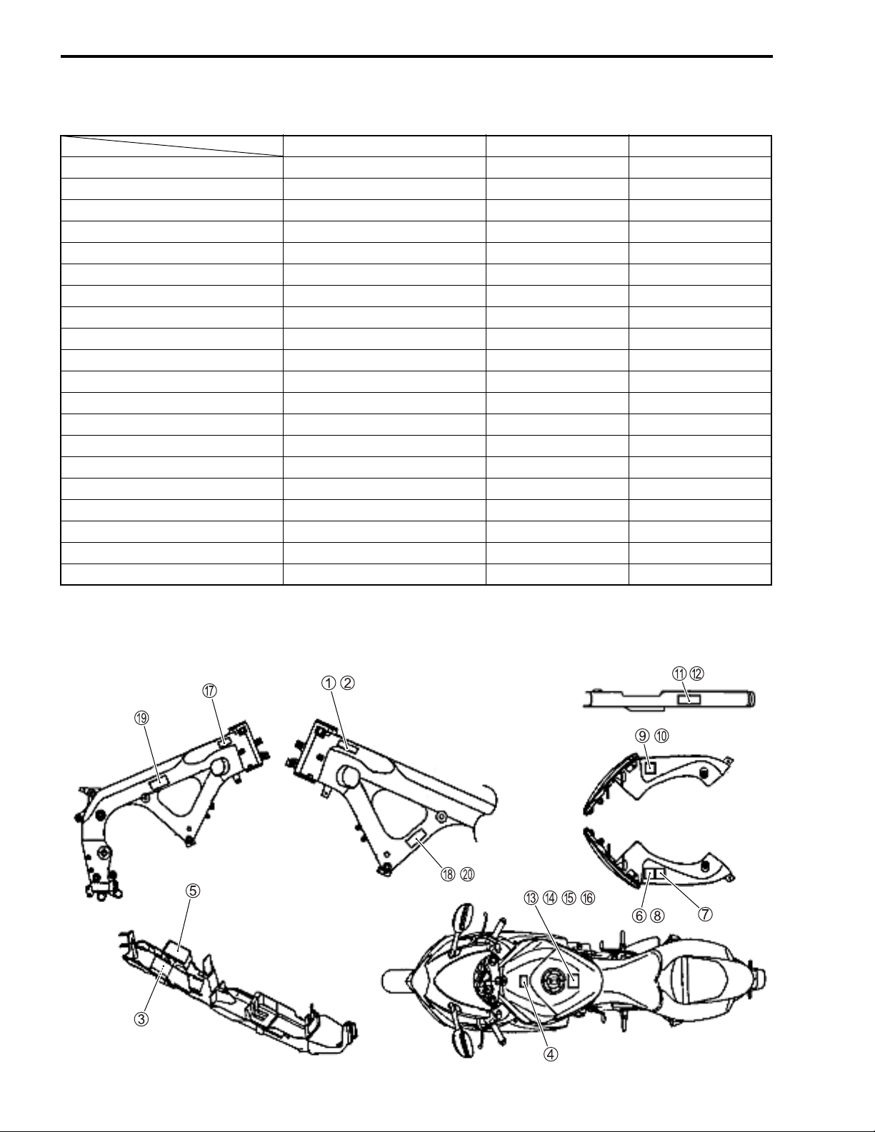
INFORMATION LABELS
GSX-R600 GSX-R600UE GSX-R600UF
1 Noise label A (For E-03, 24, 33)
2 Information label A (For E-03, 28, 33)
3 Vacuum hose routing label A (For E-33)
4 Fuel caution label A (For E-02, 24)
5 Manual notice label A (For E-03, 33)
6 Screen label A (Except E-19 )
7 Screen label A (For E-28) A
8 Screen label A (For E-19) A
9 Warning steering label A (For E-03, 33)
0 Warning steering label A (Except E-03, 33) A A
A Tire information label A (For E-03, 33)
B Tire information label A (Except E-03, 33) A A
C General warning label A (Except E-19, 28)
D General warning label A
E General warning label A (For E-28)
F General warning label A (For E-19) A
G ICES Canada label A (For E-28)
H I.D. plate A (For E-02, 19, 24) A A
I E-19 I.D. label A
J Safety plate A (For E-03, 28, 33)
A: Attached
*1: Rear fender (front)
*2: Chain case
*2
*1
Page 16

GENERAL INFORMATION 1-9
SPECIFICATIONS
DIMENSIONS AND DRY MASS
Overall length .......................................................................... 2 040 mm (80.3 in)
Overall width ........................................................................... 715 mm (28.1 in)
Overall height .......................................................................... 1 125 mm (44.3 in)
Wheelbase .............................................................................. 1 400 mm (55.1 in)
Ground clearance.................................................................... 130 mm (5.1 in)
Seat height .............................................................................. 810 mm (31.9 in)
Dry mass ................................................................................. 162 kg (357 lbs) ...........E-33
161 kg (354 lbs) ...........Others
ENGINE
Type ........................................................................................ Four stroke, liquid-cooled, DOHC
Number of cylinders ................................................................ 4
Bore......................................................................................... 67.0 mm (2.638 in)
Stroke ...................................................................................... 42.5 mm (1.673 in)
Displacement .......................................................................... 599 cm³ (36.5 cu. in)
Compression ratio ................................................................... 12.5 : 1
Fuel system............................................................................. Fuel injection
Air cleaner ............................................................................... Paper element
Starter system ......................................................................... Electric
Lubrication system .................................................................. Wet sump
Idle speed................................................................................ 1 300 ± 100 r/min
DRIVE TRAIN
Clutch ...................................................................................... Wet multi-plate type
Transmission........................................................................... 6-speed constant mesh
Gearshift pattern ..................................................................... 1-down, 5-up
Primary reduction ratio ............................................................ 1.974 (77/39)
Gear ratios, Low ...................................................................... 2.785 (39/14)
2nd....................................................................... 2.052 (39/19)
3rd........................................................................ 1.714 (36/21)
4th........................................................................ 1.500 (36/24)
5th........................................................................ 1.347 (31/23)
Top....................................................................... 1.208 (29/24)
Final reduction ratio................................................................. 2.687 (43/16)
Drive chain .............................................................................. RK525SMOZ7Y, 114 links
Page 17

1-10 GENERAL INFORMATION
CHASSIS
Front suspension .................................................................... Inverted telescopic, coil spring, oil damped
Rear suspension ..................................................................... Link type, coil spring, oil damped
Front fork stroke...................................................................... 120 mm (4.7 in)
Rear wheel travel .................................................................... 130 mm (5.1 in)
Steering angle......................................................................... 27°
Caster ..................................................................................... 23° 45’
Trail ......................................................................................... 97 mm (3.8 in)
Turning radius ......................................................................... 3.4 m (11.2 ft)
Front brake.............................................................................. Disc brake, twin
Rear brake .............................................................................. Disc brake
Front tire size .......................................................................... 120/70 ZR 17 M/C (58 W), tubeless
Rear tire size........................................................................... 180/55 ZR 17 M/C (73 W), tubeless
ELECTRICAL
Ignition type............................................................................. Electronic ignition (Transistorized)
Ignition timing.......................................................................... 6° B.T.D.C.at 1 300 r/min
Spark plug............................................................................... NGK CR9E or DENSO U27ESR-N
Battery..................................................................................... 12 V 28.8 kC (8 Ah)/10 HR
Generator ................................................................................ Three-phase A.C. generator
Main fuse ................................................................................ 30 A
Fuse ........................................................................................ 10/10/15/15/10/10 A
Headlight ................................................................................. 12 V 55 W (H7) + 12 V 65 W (H9)
Turn signal light....................................................................... 12 V 21 W
License plate light ................................................................... 12 V 5 W
Brake light/Taillight.................................................................. LED
Position light............................................................................ 12 V 5 W × 2
Speedometer light................................................................... LED
Tachometer light ..................................................................... LED
Neutral indicator light .............................................................. LED
High beam indicator light ........................................................ LED
Turn signal indicator light ........................................................ LED
Fuel level indicator light .......................................................... LED
Oil pressure/Coolant temperature/FI warning light
Engine RPM indicator light...................................................... LED
Immobilizer indicator light ....................................................... LED .........E-02, 19, 24
..................... LED
CAPACITIES
Fuel tank, including reserve .................................................... 15.5 L (4.1/3.4 US/lmp gal) ......E-33
16.5 L (4.4/3.6 US/lmp gal) ......Others
Engine oil, oil change ............................................................. 2 200 ml (2.3/1.9 US/Imp qt)
with filter change .................................................. 2 500 ml (2.6/2.2 US/lmp qt)
overhaul................................................................ 2 900 ml (3.1/2.6 US/lmp qt)
Coolant.................................................................................... 2.7 L (2.9/2.4 US/lmp qt)
These specifications are subject to change without notice.
Page 18

PERIODIC MAINTENANCE 2-1
PERIODIC MAINTENANCE
CONTENTS
PERIODIC MAINTENANCE SCHEDULE .................................................... 2- 2
PERIODIC MAINTENANCE CHART..................................................... 2- 2
LUBRICATION POINTS ........................................................................ 2- 3
MAINTENANCE AND TUNE-UP PROCEDURES ....................................... 2- 4
AIR CLEANER....................................................................................... 2- 4
SPARK PLUG........................................................................................ 2- 5
VALVE CLEARANCE............................................................................ 2- 7
ENGINE OIL AND OIL FILTER............................................................. 2-12
EXHAUST CONTROL VALVE .............................................................. 2-13
FUEL LINE............................................................................................. 2-14
ENGINE IDLE SPEED ........................................................................... 2-14
THROTTLE VALVE SYNCHRONIZATION ........................................... 2-15
EVAPORATIVE EMISSION CONTROL SYSTEM (E-33 ONLY) .......... 2-15
PAIR (AIR SUPPLY) SYSTEM .............................................................. 2-15
THROTTLE CABLE PLAY .................................................................... 2-15
CLUTCH ................................................................................................ 2-16
COOLING SYSTEM............................................................................... 2-17
DRIVE CHAIN........................................................................................ 2-20
BRAKE .................................................................................................. 2-23
TIRES..................................................................................................... 2-27
STEERING............................................................................................. 2-27
FRONT FORK........................................................................................ 2-28
REAR SUSPENSION ............................................................................ 2-28
EXHAUST PIPE BOLT AND NUT......................................................... 2-29
CHASSIS BOLTS AND NUTS .............................................................. 2-30
COMPRESSION PRESSURE CHECK ........................................................ 2-32
COMPRESSION TEST PROCEDURE .................................................. 2-32
OIL PRESSURE CHECK ............................................................................. 2-33
SDS CHECK................................................................................................. 2-34
2
Page 19
2-2 PERIODIC MAINTENANCE
PERIODIC MAINTENANCE SCHEDULE
The chart below lists the recommended intervals for all the required periodic service work necessary to keep
the motorcycle operating at peak performance and economy. Mileages are expressed in terms of kilometers, miles and time for your convenience.
IMPORTANT (For E-28): The periodic maintenance intervals and service requirements have been established in accordance with EPA regulations. Following these instructions will ensure that the motorcycle will
not exceed emission standards and it will also ensure the reliability and performance of the motorcycle.
NOTE:
More frequent servicing may be required on motorcycles that are used under severe conditions.
PERIODIC MAINTENANCE CHART
Interval
Item
Air cleaner element ---- I I R I
Spark plugs ---- I R I R
Va l v e c le ar a n c e ---- ---- ---- ---- I
E x h a u s t c o n t r o l va l ve I ---- I ---- I
Engine oil R R R R R
E n g i n e o il fi lt e r R ---- ---- R ---Fuel line ----IIII
Idle speed IIIII
Throttle valve synchronization
Evaporative emission control system
(E-33 only)
PAIR (air supply) system ---- ---- I ---- I
Throttle cable play I I I I I
Clutch cable play ---- I I I I
Radiator hoses ---- I I I I
Engine coolant Replace every 2 years.
Drive chain III II
Brakes I I I I I
Brake hoses
Brake fluid
Tires ----IIII
S te er in g I ---- I ---- I
Fro nt fo r k s ---- ---- I ---- I
R e a r s u s p e ns i o n ---- ---- I ---- I
E x h a u s t pi pe b o l t s a n d m uf fl e r b o l t a nd n u t T ---- T ---- T
Chassis bolts and nuts T T T T T
miles
km
months
600 4 000 7 500 11 000 14 500
1 000 6 000 12 000 18 000 24 000
212243648
I
(E-33 only)
---- ---- I ---- I
Clean and lubricate every 1 000 km (600 miles).
----IIII
----IIII
---- I ---- I
Replace every 4 years.
Replace every 2 years.
NOTE:
I = Inspect and clean, adjust, replace or lubricate as necessary; R = Replace; T = Tighten
Page 20
PERIODIC MAINTENANCE 2-3
LUBRICATION POINTS
Proper lubrication is important for smooth operation and long life of each working part of the motorcycle.
Major lubrication points are indicated below.
Brake lever holder
Brake pedal pivot and footrest pivot
Clutch lever holder
Footrest pivot and
gearshift lever pivot
Side-stand pivot
and spring hook
Drive chain
NOTE:
* Before lubricating each part, clean off any rusty spots and wipe off any grease, oil, dirt or grime.
* Lubricate exposed parts which are subject to rust, with a rust preventative spray whenever the motorcycle
has been operated under wet or rainy conditions.
Page 21
2-4 PERIODIC MAINTENANCE
MAINTENANCE AND TUNE-UP PROCEDURES
This section describes the servicing procedures for each item of
the Periodic Maintenance requirements.
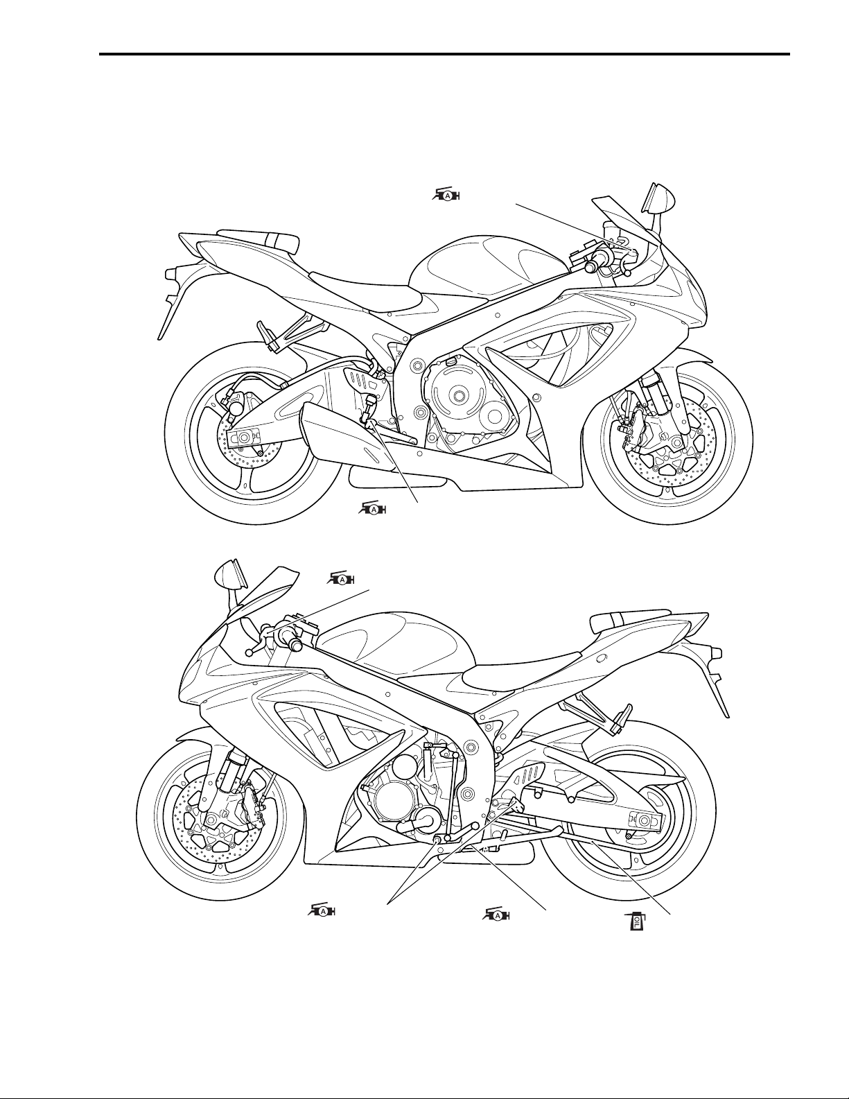
AIR CLEANER
Inspect every 6 000 km (4 000 miles, 12 months).
Replace every 18 000 km (11 000 miles, 36 months).
• Remove the front seat. (8-7)
• Lift and support the fuel tank. (5-3)
• Remove the air cleaner element by removing the screws.
• Remove the air cleaner element.
• Inspect the air cleaner element for clogging.
If the air cleaner element is clogged with dust, replace the air
cleaner element with a new one.
Do not blow the air cleaner element with compressed
air.
NOTE:
If driving under dusty conditions, replace the air cleaner element
more frequently. Make sure that the air cleaner is in good condition at all times. The life of the engine depends largely on this
component.
• Install a new air cleaner element in the reverse order of
removal.
• Remove the drain plug from the air cleaner box to allow any
water to drain out.
Page 22

SPARK PLUG
Inspect every 6 000 km (4 000 miles, 12 months).
Replace every 12 000 km (7 500 miles, 24 months).
SPARK PLUG AND IGNITION COIL/PLUG CAP REMOVAL
• Remove the front seat. (8-7)
• Lift and support the fuel tank. (5-3)
• Remove the air cleaner box. (5-14)
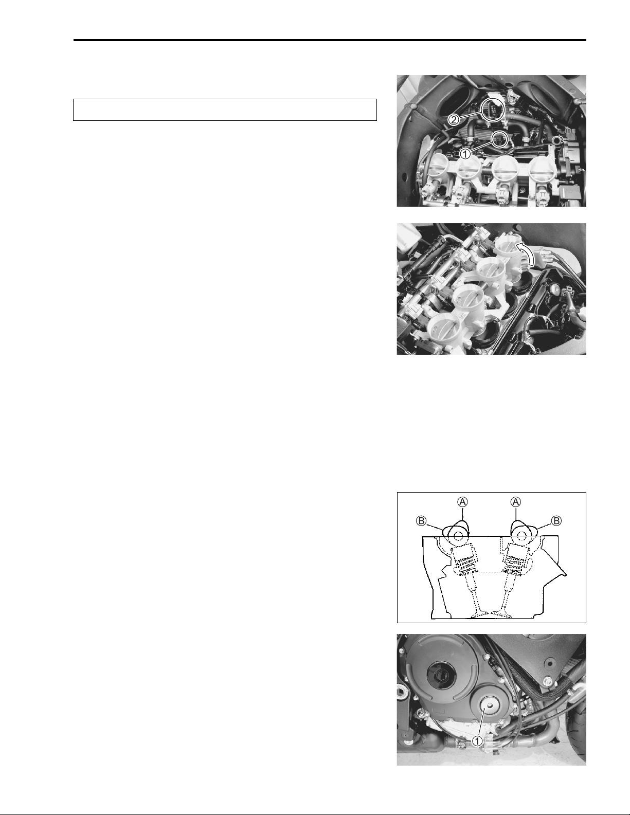
• Disconnect all lead wire couplers from ignition coil/plug caps.
Disconnect the lead wire coupler before removing the
ignition coil/plug cap to avoid lead wire coupler damage.
• Remove the ignition coils/plug caps.
PERIODIC MAINTENANCE 2-5
* Do not pry up the ignition coil/plug cap with a screw
driver or a bar to avoid its damage.
* Be careful not to drop the ignition coil/plug cap to
prevent short/open circuit.
• Remove the spark plugs with a spark plug wrench.
HEAT RANGE
• Check spark plug heat range by observing electrode color. If
the electrode of the spark plug is wet appearing or dark color,
replace the spark plug with hotter type one. If it is white or
glazed appearing, replace the spark plug with colder type
one.
Hot type Standard Cold type
NGK CR8E CR9E CR10E
ND U24ESR-N U27ESR-N U31ESR-N
NOTE:
“R” type spark plug has a resistor built into at the center electrode to prevent radio noise.
CARBON DEPOSITS
• Check carbon deposits on the spark plug.
• If carbon is deposited, remove it using a spark plug cleaner
machine or carefully use a tool with a pointed end.
Page 23
2-6 PERIODIC MAINTENANCE
SPARK PLUG GAP
• Measure the spark plug gap with a thickness gauge.
• Adjust the spark plug gap if necessary.
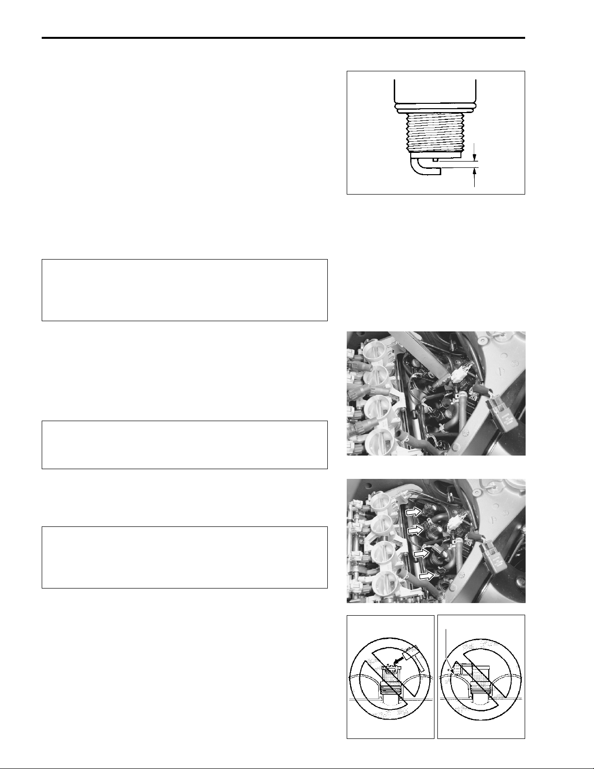
Spark plug gap:
Standard: 0.7 – 0.8 mm (0.028 – 0.031 in)
09900-20803: Thickness gauge
ELECTRODE’S CONDITION
• Check the condition of the electrode.
• If it is extremely worn or burnt, replace the spark plug.
Replace the spark plug if it has a broken insulator, damaged
thread, etc.
Confirm the thread size and reach when replacing the
plug. If the reach is too short, carbon will be deposited
on the screw portion of the plug hole and engine damage may result.
SPARK PLUG AND IGNITION COIL/PLUG CAP
INSTALLATION
• Screw the spark plugs into the cylinder head with fingers, and
then tighten them to the specified torque.
Spark plug: 11 N·m (1.1 kgf-m, 8.0 Ib-ft)
Do not cross thread or over tighten the spark plug, or
such an operation will damage the aluminum threads
of the cylinder head.
• Install the ignition coils/plug caps and connect their lead wire
couplers.
* Do not hit the ignition coil/plug cap with a plastic
hammer when installing it.
* Place the ignition coil/spark plug cap so that the cou-
pler does not touch the cylinder head cover.
INCORRECT
CONTACT
INCORRECT
Page 24
VALVE CLEARANCE
Inspect every 24 000 km (14 500 miles, 48 months).
• Remove the right under cowling. (8-5)
• Lift and support the fuel tank. (5-3)
• Remove the air cleaner box. (5-14)
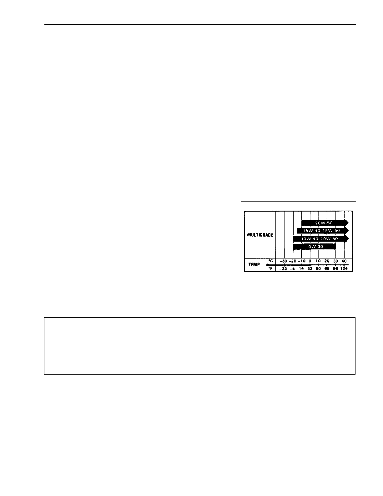
• Disconnect the CMP sensor coupler 1.
• Remove the PAIR control solenoid valve 2.
• Remove the spark plugs. (2-5)
• Loosen the throttle body clamp screws at the intake pipe side.
• Move the throttle body assembly.
• Move the radiator forward. (6-10)
• Remove the regulator/rectifier and horn. (3-6)
• Remove the cylinder head cover. (3-14)
PERIODIC MAINTENANCE 2-7
The valve clearance specification is different for intake and
exhaust valves. Valve clearance must be checked and adjusted,
1) at the time of periodic inspection, 2) when the valve mechanism is serviced, and 3) when the camshafts are removed for
servicing.
Valve clearance (when cold):
Standard: IN. : 0.08 – 0.18 mm (0.003 – 0.007 in)
EX. : 0.18 – 0.28 mm (0.007 – 0.011 in)
NOTE:
* The cam must be at positions,
A
or B, when checking or
adjusting the valve clearance. Clearance readings should not
be taken with the cam in any other position than these two
positions.
* The clearance specification is for COLD state.
* To turn the crankshaft for clearance checking, be sure to use a
wrench, and rotate in the normal running direction. All spark
plugs should be removed.
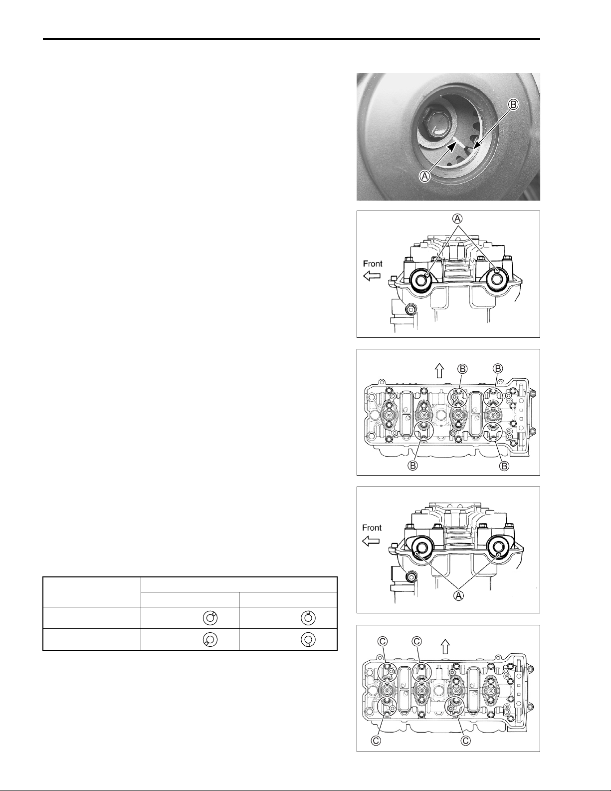
• Remove the valve timing inspection cap 1.
EX. IN.
Page 25
2-8 PERIODIC MAINTENANCE
• Turn the crankshaft to bring the line A on the CKP sensor
rotor to the rib B behind the clutch cover and also to bring the
notches A on the left ends of both camshafts (Ex. and In.) to
the positions as shown.
• In this condition, read the valve clearance at the valves B (In.
and Ex. of No. 4 cylinder, Ex. of No. 3 and In. of No. 2).
• If the clearance is out of specification, adjust the clearance.
(2-9)
09900-20803: Thickness gauge
• Turn the crankshaft 360 degrees (one rotation) to bring the
line on the CKP sensor rotor to the index mark of valve timing
inspection hole and also to bring the notches A to the position as shown.
• Read the clearance at the rest of the valves C and adjust the
clearance if necessary. (2-9)
Cam position
Exhaust Camshaft Intake Camshaft
Notch A position
B ← Front ← Front
C
← Front ← Front
Front
Front
Page 26
VALVE CLEARANCE ADJUSTMENT
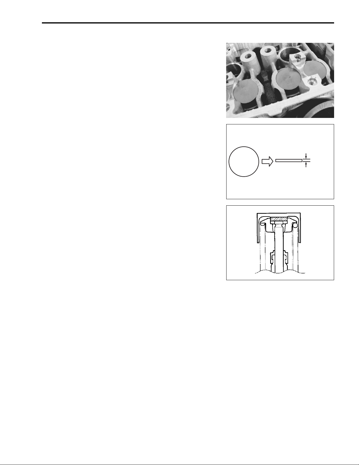
The clearance is adjusted by replacing the existing tappet shim
by a thicker or thinner shim.
• Remove the intake or exhaust camshafts. (3-14)
• Remove the tappet and shim by fingers or magnetic hand.
• Check the figures printed on the shim. These figures indicate
the thickness of the shim, as illustrated.
• Select a replacement shim that will provide a clearance within
the specified range. For the purpose of this adjustment, a total
of 21 sizes of tappet shim are available ranging from 1.20 to
2.20 mm in steps of 0.05 mm. Fit the selected shim to the
valve stem end, with numbers toward tappet. Be sure to
check shim size with micrometer to ensure its size. Refer to
the tappet shim selection table (2-10 and -11) for details.
170
PERIODIC MAINTENANCE 2-9
1.70 mm
NOTE:
* Be sure to apply engine oil to tappet shim top and bottom
faces.
* When seating the tappet shim, be sure the figure printed sur-
face faces the tappet.
NOTE:
Reinstall the camshafts in the specified manner. (
• After replacing the tappet shim and camshafts, rotate the
engine so that the tappet is depressed fully. This will squeeze
out oil trapped between the shim and the tappet that could
cause an incorrect measurement. Then check the clearance
again to confirm that it is within the specified range.
• After finishing the valve clearance adjustment, reinstall the following items.
* Cylinder head cover (3-97)
* Spark plug and plug cap (2-6)
* Throttle body assembly (5-21)
* Valve timing inspection plug (3-97)
* PAIR control solenoid valve (11-7)
3-92)
Page 27
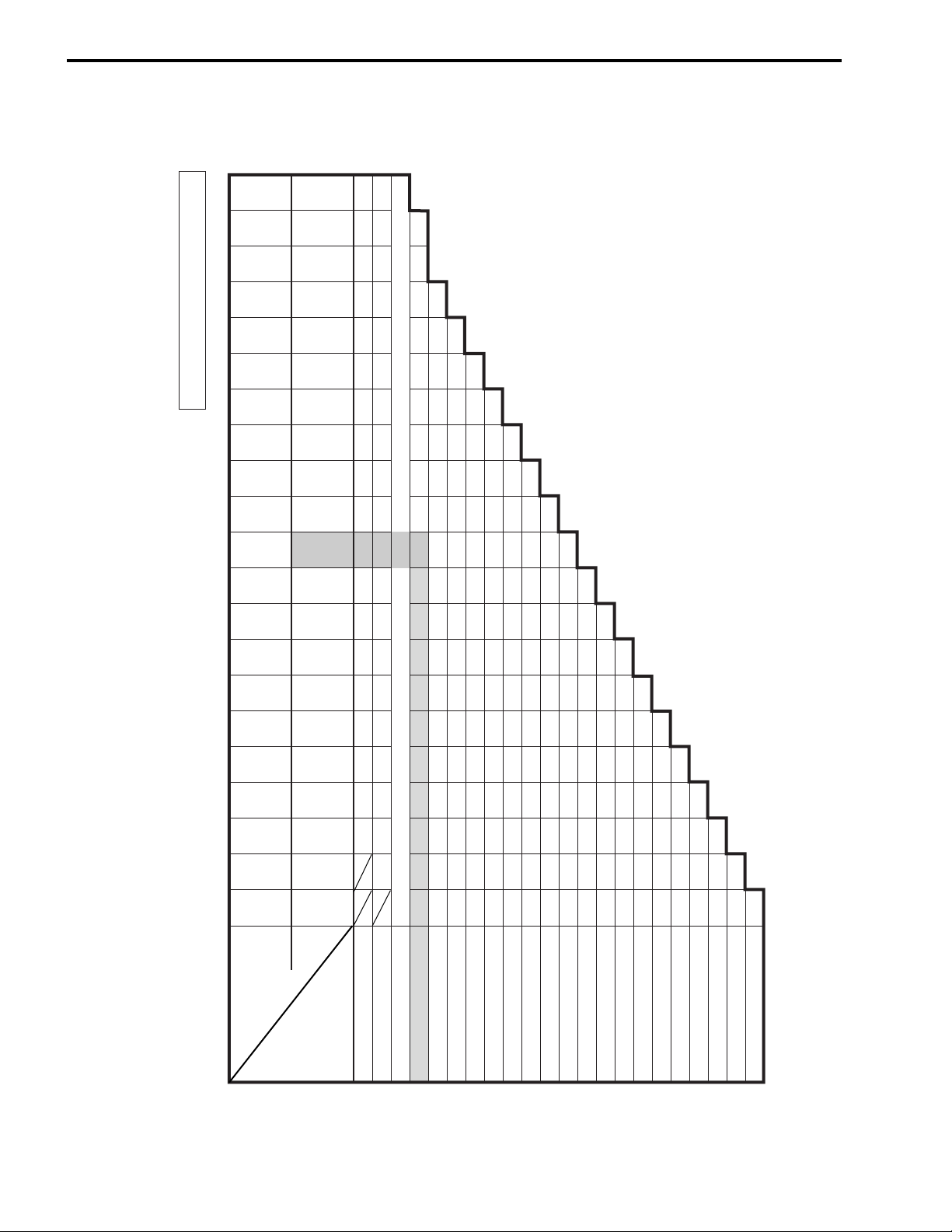
2-10 PERIODIC MAINTENANCE
(INTAKE SIDE)
TAPPET SHIM SET (12800-05830)
TAPPET SHIM SELECTION TABLE [INTAKE]
TAPPET SHIM NO. (12892-05C00-XXX)
140 145 150 155 160 165 170 175 180 185 190 195 200 205 210 215 220
120 125 130 135
NO.
SUFFIX
1.40 1.45 1.50 1.55 1.60 1.65 1.70 1.75 1.80 1.85 1.90 1.95 2.00 2.05 2.10 2.15 2.20
1.20 1.25 1.30 1.35
(mm)
PRESENT
SHIM SIZE
EXAMPLE
column.
HOW TO USE THIS CHART:
I. Measure valve clearance. “ENGINE IS COLD”
II. Measure present shim size.
III. Match clearance in vertical column with present shim size in horizontal
Valve clearance is 0.23 mm
Present shim size 1.70 mm
Shim size to be used 1.80 mm
MEASURED
VALVE
CLEARANCE
(mm)
0.00 – 0.04 1.20 1.25 1.30 1.35 1.40 1.45 1.50 1.55 1.60 1.65 1.70 1.75 1.80 1.85 1.90 1.95 2.00 2.05 2.10
0.05 – 0.09 1.20 1.25 1.30 1.35 1.40 1.45 1.50 1.55 1.60 1.65 1.70 1.75 1.80 1.85 1.90 1.95 2.00 2.05 2.10 2.15
0.10 – 0.20 SPECIFIED CLEARANCE/NO ADJUSTMENT REQUIRED
0.21 – 0.25 1.30 1.35 1.40 1.45 1.50 1.55 1.60 1.65 1.70 1.75 1.80 1.85 1.90 1.95 2.00 2.05 2.10 2.15 2.20 2.20
0.26 – 0.30 1.35 1.40 1.45 1.50 1.55 1.60 1.65 1.70 1.75 1.80 1.85 1.90 1.95 2.00 2.05 2.10 2.15 2.20
0.31 – 0.35 1.40 1.45 1.50 1.55 1.60 1.65 1.70 1.75 1.80 1.85 1.90 1.95 2.00 2.05 2.10 2.15 2.20
0.36 – 0.40 1.45 1.50 1.55 1.60 1.65 1.70 1.75 1.80 1.85 1.90 1.95 2.00 2.05 2.10 2.15 2.20
0.41 – 0.45 1.50 1.55 1.60 1.65 1.70 1.75 1.80 1.85 1.90 1.95 2.00 2.05 2.10 2.15 2.20
0.46 – 0.50 1.55 1.60 1.65 1.70 1.75 1.80 1.85 1.90 1.95 2.00 2.05 2.10 2.15 2.20
0.51 – 0.55 1.60 1.65 1.70 1.75 1.80 1.85 1.90 1.95 2.00 2.05 2.10 2.15 2.20
0.56 – 0.60 1.65 1.70 1.75 1.80 1.85 1.90 1.95 2.00 2.05 2.10 2.15 2.20
0.61 – 0.65 1.70 1.75 1.80 1.85 1.90 1.95 2.00 2.05 2.10 2.15 2.20
0.66 – 0.70 1.75 1.80 1.85 1.90 1.95 2.00 2.05 2.10 2.15 2.20
0.71 – 0.75 1.80 1.85 1.90 1.95 2.00 2.05 2.10 2.15 2.20
0.76 – 0.80 1.85 1.90 1.95 2.00 2.05 2.10 2.15 2.20
0.81 – 0.85 1.90 1.95 2.00 2.05 2.10 2.15 2.20
0.86 – 0.90 1.95 2.00 2.05 2.10 2.15 2.20
0.91 – 0.95 2.00 2.05 2.10 2.15 2.20
0.96 – 1.00 2.05 2.10 2.15 2.20
1.01 – 1.05 2.10 2.15 2.20
1.06 – 1.10 2.15 2.20
1.11 – 1.15 2.20
Page 28
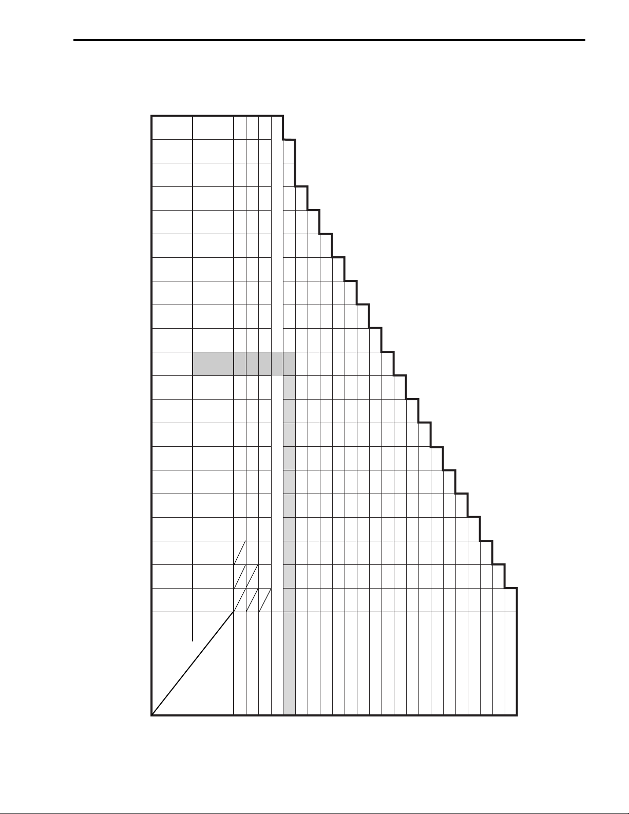
(EXHAUST SIDE)
TAPPET SHIM SET (12800-05830)
PERIODIC MAINTENANCE 2-11
TAPPET SHIM SELECTION TABLE [EXHAUST]
TAPPET SHIM NO. (12892-05C00-XXX)
140 145 150 155 160 165 170 175 180 185 190 195 200 205 210 215 220
120 125 130 135
NO.
SUFFIX
1.40 1.45 1.50 1.55 1.60 1.65 1.70 1.75 1.80 1.85 1.90 1.95 2.00 2.05 2.10 2.15 2.20
1.20 1.25 1.30 1.35
(mm)
PRESENT
SHIM SIZE
1.20 1.25 1.30 1.35 1.40 1.45 1.50 1.55 1.60 1.65 1.70 1.75 1.80 1.85 1.90 1.95 2.00 2.05
1.20 1.25 1.30 1.35 1.40 1.45 1.50 1.55 1.60 1.65 1.70 1.75 1.80 1.85 1.90 1.95 2.00 2.05 2.100.10 – 0.14
1.20 1.25 1.30 1.35 1.40 1.45 1.50 1.55 1.60 1.65 1.70 1.75 1.80 1.85 1.90 1.95 2.00 2.05 2.10 2.15
SPECIFIED CLEARANCE/NO ADJUSTMENT REQUIRED
1.30 1.35 1.40 1.45 1.50 1.55 1.60 1.65 1.70 1.75 1.80 1.85 1.90 1.95 2.00 2.05 2.10 2.15 2.20 2.20
1.35 1.40 1.45 1.50 1.55 1.60 1.65 1.70 1.75 1.80 1.85 1.90 1.95 2.00 2.05 2.10 2.15 2.20
1.40 1.45 1.50 1.55 1.60 1.65 1.70 1.75 1.80 1.85 1.90 1.95 2.00 2.05 2.10 2.15 2.20
1.45 1.50 1.55 1.60 1.65 1.70 1.75 1.80 1.85 1.90 1.95 2.00 2.05 2.10 2.15 2.20
1.50 1.55 1.60 1.65 1.70 1.75 1.80 1.85 1.90 1.95 2.00 2.05 2.10 2.15 2.20
1.55 1.60 1.65 1.70 1.75 1.80 1.85 1.90 1.95 2.00 2.05 2.10 2.15 2.20
1.60 1.65 1.70 1.75 1.80 1.85 1.90 1.95 2.00 2.05 2.10 2.15 2.20
1.65 1.70 1.75 1.80 1.85 1.90 1.95 2.00 2.05 2.10 2.15 2.20
1.70 1.75 1.80 1.85 1.90 1.95 2.00 2.05 2.10 2.15 2.20
1.75 1.80 1.85 1.90 1.95 2.00 2.05 2.10 2.15 2.20
1.80 1.85 1.90 1.95 2.00 2.05 2.10 2.15 2.20
1.85 1.90 1.95 2.00 2.05 2.10 2.15 2.20
1.90 1.95 2.00 2.05 2.10 2.15 2.20
HOW TO USE THIS CHART:
I. Measure valve clearance. “ENGINE IS COLD”
II. Measure present shim size.
III. Match clearance in vertical column with present shim size in horizontal
1.95 2.00 2.05 2.10 2.15 2.20
2.00 2.05 2.10 2.15 2.20
2.05 2.10 2.15 2.20
2.10 2.15 2.20
2.15 2.20
EXAMPLE
column.
Valve clearance is 0.33 mm
Present shim size 1.70 mm
Shim size to be used 1.80 mm
MEASURED
VALV E
CLEARANCE
(mm)
0.05 – 0.09
0.15 – 0.19
0.20 – 0.30
0.31 – 0.35
0.36 – 0.40
0.41 – 0.45
0.46 – 0.50
0.51 – 0.55
0.56 – 0.60
0.61 – 0.65
0.66 – 0.70
0.71 – 0.75
0.76 – 0.80
0.81 – 0.85
0.86 – 0.90
0.91 – 0.95
0.96 – 1.00
1.01 – 1.05
1.06 – 1.10
1.11 – 1.15
1.16 – 1.20
1.21 – 1.25 2.20
Page 29
2-12 PERIODIC MAINTENANCE
ENGINE OIL AND OIL FILTER
(ENGINE OIL)
Replace initially at 1 000 km (600 miles, 2 months) and
every 6 000 km (4 000 miles, 12 months) thereafter.
(OIL FILTER)
Replace initially at 1 000 km (600 miles, 2 months) and
every 18 000 km (11 000 miles, 36 months) thereafter.
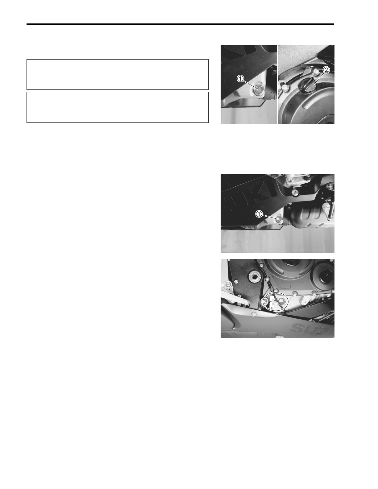
ENGINE OIL REPLACEMENT
• Remove the under cowlings. (8-5)
• Keep the motorcycle upright.
• Place an oil pan below the engine, and drain oil by removing
the oil drain plug 1 and filler cap 2.
• Tighten the drain plug 1 to the specified torque, and pour
fresh oil through the oil filler. The engine will hold about 2.2 L
(2.3/1.9 US/Imp qt) of oil. Use of SF/SG or SH/SJ in API with
MA in JASO.
Oil drain plug: 23 N·m (2.3 kgf-m, 16.5 lb-ft)
• Start up the engine and allow it to run for several minutes at
idling speed.
• Turn off the engine and wait about three minutes, then check
the oil level through the inspection window. If the level is
below mark “L”, add oil to “F” level. If the level is above mark
“F”, drain oil to “F” level.
F
L
Page 30
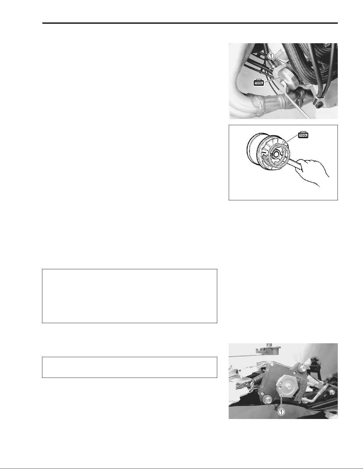
OIL FILTER REPLACEMENT
• Drain the engine oil as described in the engine oil replacement procedure.
• Remove the oil filter 1 with the special tool.
09915-40610: Oil filter wrench
• Apply engine oil lightly to the gasket of the new oil filter before
installation.
• Install the new oil filter. Turn it by hand until you feel that the
oil filter gasket contacts the oil filter mounting surface. Then,
tighten the oil filter two full turns (or to specified torque) with
the special tool.
NOTE:
To properly tighten the oil filter, use the special tool. Never
tighten the oil filter by hand.
Oil filter: 20 N·m (2.0 kgf-m, 14.5 lb-ft)
PERIODIC MAINTENANCE 2-13
After contacting the
gasket, tighten 2 turns.
(20 N·m, 2.0 kgf-m, 14.5 lb-ft)
• Add new engine oil and check the oil level is as described in
the engine oil replacement procedure.
NECESSARY AMOUNT OF ENGINE OIL:
Oil change : 2.2 L (2.3/1.9 US/Imp qt)
Oil and filter change : 2.5 L (2.6/2.2 US/Imp qt)
Engine overhaul : 2.9 L (3.1/2.6 US/Imp qt)
ONLY USE A GENUINE SUZUKI MOTORCYCLE OIL
FILTER. Other manufacturer’s oil filters may differ in
thread specifications (thread diameter and pitch), filtering performance and durability which may lead to
engine damage or oil leaks. Also, do not use a genuine
Suzuki automobile oil filter on this motorcycle.
EXHAUST CONTROL VALVE
Inspect initially at 1 000 km (600 miles, 2 months) and
every 12 000 km (7 500 miles, 24 months) thereafter.
Exhaust control valve actuator is installed in the right-hand side
in tail cowl.
Check the exhaust control valve actuator 1 for its movement
when the ignition switch is turned ON. If the exhaust valve actuator does not move, check exhaust valve actuator electrical circuit and exhaust valve carbon sticking. Check the exhaust
control cable play. (6-14)
Page 31

2-14 PERIODIC MAINTENANCE
• Remove the under cowlings. (8-5)
• Check the lock-nuts tightness. If the lock-nuts are loose,
adjust the cable play and tighten the lock-nuts.
FUEL LINE
Inspect initially 6 000 km (4 000 miles, 12 months).
• Inspect the fuel feed hose 1 for damage and fuel leakage. If
any defects are found, the fuel feed hose must be replaced.
ENGINE IDLE SPEED
Inspect initially at 1 000 km (600 miles, 2 months) and
every 6 000 km (4 000 miles, 12 months) thereafter.
NOTE:
Warm up the engine before adjusting the engine idle speed.
• Start the engine, turn the throttle stop screw and set the
engine idle speed as follows.
Engine idle speed: 1 300 ± 100 r/min
Page 32

THROTTLE VALVE SYNCHRONIZATION
Inspect initially at 1 000 km (600 miles, 2 months) (E-33
only) and every 12 000 km (7 500 miles, 24 moths).
• Inspect the throttle valve synchronization periodically.
(5-26)
EVAPORATIVE EMISSION CONTROL
SYSTEM (E-33 ONLY)
Inspect every 12 000 km (7 500 miles, 24 months).
Replace vapor hose every 4 years.
• Inspect the evaporative emission control system periodically.
PAIR (AIR SUPPLY) SYSTEM
PERIODIC MAINTENANCE 2-15
Inspect every 12 000 km (7 500 miles, 24 months).
• Inspect the PAIR (air supply) system periodically. (11-6)
THROTTLE CABLE PLAY
Inspect initially at 1 000 km (600 miles, 2 months) and
every 6 000 km (4 000 miles, 12 months) thereafter.
• Adjust the throttle cable play A as follows.
• Loosen the lock-nut 2 of the throttle pulling cable 1.
• Turn the adjuster 3 in or out until the throttle cable play (at
the throttle grip) A is between 2.0 – 4.0 mm (0.08 – 0.16 in).
• Tighten the lock-nut 2 while holding the adjuster 3.
Throttle cable play A: 2.0 – 4.0 mm (0.08 – 0.16 in)
After the adjustment is completed, check that handlebar movement does not raise the engine idle speed
and that the throttle grip returns smoothly and automatically.
Page 33

2-16 PERIODIC MAINTENANCE
CLUTCH
Inspect every 6 000 km (4 000 miles, 12 months).
• Lift and support the fuel tank with its prop stay. (5-3)
• Turn in the adjuster 1 all the way into the clutch lever assem-
bly.
• Loosen the lock-nut 2 and turn the clutch cable adjuster 3
to obtain proper cable play.
• Remove the clutch release adjuster cap.
• Loosen the lock-nut 4 and turn out the adjusting screw 5
two or three rotations.
• From that position, slowly turn in the adjusting screw 5 until
resistance is felt.
• From this position, turn out the adjusting screw 5 1/2 rotation,
and tighten the lock-nut 4 while holding the screw 5.
• Turn the cable adjuster 3 to obtain 10 – 15 mm (0.4 – 0.6 in)
of free play A at the clutch lever end.
• Tighten the lock-nut 2.
Clutch lever play A: 10 – 15 mm (0.4 – 0.6 in)
Clutch release screw: 1/2 turn out
Clutch release adjuster cap: 11 N·m (1.1 kgf-m, 8.0 lb-ft)
Page 34

COOLING SYSTEM
Inspect every 6 000 km (4 000 miles, 12 months).
Replace engine coolant every 2 years.
ENGINE COOLANT LEVEL CHECK
• Keep the motorcycle upright.
• Check the engine coolant level by observing the full and lower
lines on the engine coolant reservoir.
A Full line B Lower line
• If the level is below the lower line, remove the right under
cowling (8-5), and add engine coolant to the full line from
the engine coolant reservoir filler.
PERIODIC MAINTENANCE 2-17
ENGINE COOLANT CHANGE
• Remove the under cowlings. (8-5)
• Remove the radiator cap 1.
• Drain engine coolant by disconnecting the radiator hose 2
from the pump.
* Do not open the radiator cap when the engine is hot,
as you may be injured by escaping hot liquid or
vapor.
* Engine coolant may be harmful if swallowed or if it
comes in contact with skin or eyes. If engine coolant
gets into the eyes or in contact with the skin, flush
thoroughly with plenty of water. If swallowed, induce
vomiting and call physician immediately!
• Flush the radiator with fresh water if necessary.
• Connect the radiator hose 2 securely.
• Pour the specified engine coolant up to the radiator inlet.
Engine coolant capacity (excluding reservoir):
2 400 ml (2.5/2.1 US/lmp qt)
• Bleed the air from the engine coolant circuit in the following
procedure. (2-18)
ENGINE COOLANT INFORMATION (7-2)
Page 35

2-18 PERIODIC MAINTENANCE
AIR BLEEDING THE COOLING CIRCUIT
• Add engine coolant up to the radiator inlet.
• Support the motorcycle upright.
• Slowly swing the motorcycle, right and left, to bleed the air
trapped in the cooling circuit.
• Add engine coolant up to the radiator inlet.
• Start up the engine and bleed air from the radiator inlet completely.
• Add engine coolant up to the radiator inlet.
• Repeat the above procedure until no air bleeds from the radiator inlet.
• Loosen the air bleeding bolt 1 and check that the engine
coolant flows out.
• Close the air bleeding bolt securely.
• Close the radiator cap securely.
• After warming up and cooling down the engine several times,
add the engine coolant up to the full level of the reservoir.
Repeat the above procedure several times and make
sure that the radiator is filled with engine coolant up to
the reservoir full level.
Engine coolant capacity:
Engine side : 2 400 ml (2.5/2.1 US/Imp qt)
Reservoir tank side : 250 ml (0.3/0.2 US/lmp qt)
Page 36

RADIATOR HOSES
• Remove the under cowlings. (8-5)
• Lift and support the fuel tank. (5-3)
• Check the radiator hoses for crack, damage or engine coolant
leakage.
• If any defect is found, replace the radiator hose with new one.
PERIODIC MAINTENANCE 2-19
Page 37

2-20 PERIODIC MAINTENANCE
DRIVE CHAIN
Inspect initially at 1 000 km (600 miles, 2 months) and
every 6 000 km (4 000 miles, 12 months) thereafter.
Clean and lubricate every 1 000 km (600 miles).
Visually check the drive chain for the possible defects listed
below. (Support the motorcycle by a jack and a wooden block,
turn the rear wheel slowly by hand with the transmission shifted
to Neutral.)
* Loose pins * Excessive wear
* Damaged rollers * Improper chain adjustment
* Dry or rusted links * Missing O-ring seals
* Kinked or binding links
If any defect is found, the drive chain must be replaced.
NOTE:
When replacing the drive chain, replace the drive chain and
sprockets as a set.
Grease
O-ring
CHECKING
• Remove the axle cotter pin. (For E-03, 28, 33)
• Loosen the axle nut 1.
• Loosen the chain adjuster lock-nuts 2.
• Give tension to the drive chain fully by turning both chain
adjuster bolts 3.
Page 38

• Count out 21 pins (20 pitches) on the chain and measure the
distance between the two points. If the distance exceeds the
service limit, the chain must be replaced.
Drive chain 20-pitch length:
Service limit: 319.4 mm (12.57 in)
ADJUSTING
• Loosen or tighten both chain adjuster bolts 1 until there is 20
– 30 mm (0.8 – 1.2 in) of slack at the middle of the chain
between the engine and rear sprockets as shown. The chain
adjuster position relative to the reference marks A on both
sides of the swingarm must be equal to ensure that the front
and rear wheels are correctly aligned.
Drive chain slack:
Standard: 20 – 30 mm (0.8 – 1.2 in)
PERIODIC MAINTENANCE 2-21
1 2 3 19 20 21
20 – 30 mm
(0.8 – 1.2 in)
• Place the motorcycle on its side-stand for accurate adjustment.
• After adjusting the drive chain, tighten the axle nut 2 to the
specified torque.
• Tighten both chain adjuster lock-nuts 3 securely.
Rear axle nut: 100 N·m (10.0 kgf-m, 72.5 lb-ft)
• Install a new cotter pin. (For E-03, 28, 33)
• Recheck the drive chain slack after tightening the axle nut.
NOTE:
Do not adjust the drive chain beyond the adjustable range
A
.
Replace the drive chain before drive chain exceeds the limit.
Page 39

2-22 PERIODIC MAINTENANCE
CLEANING AND LUBRICATING
• Clean the drive chain with kerosine. If the drive chain tends to
rust quickly, the intervals must be shortened.
Do not use trichloroethylene, gasoline or any similar
solvent. These fluids will damage the O-rings. Use
only kerosine to clean the drive chain.
• After washing and drying the chain, oil it with a heavyweight
motor oil.
* Do not use any oil sold commercially as “drive chain
oil”. Such oil can damage the O-rings.
* The standard drive chain is RK525SMOZ7Y. Suzuki
recommends to use this standard drive chain as a
replacement.
Page 40

BRAKE
PERIODIC MAINTENANCE 2-23
(BRAKE)
Inspect initially at 1 000 km (600 miles, 2 months) and
every 6 000 km (4 000 miles, 12 months) thereafter.
(BRAKE HOSE AND BRAKE FLUID)
Inspect every 6 000 km (4 000 miles, 12 months).
Replace hoses every 4 years. Replace fluid every 2
years.
BRAKE FLUID LEVEL CHECK
• Keep the motorcycle upright and place the handlebars
straight.
• Check the brake fluid level relative to the lower limit lines on
the front and rear brake fluid reservoirs.
• When the level is below the lower limit line, replenish with
brake fluid that meets the following specification.
Specification and classification: DOT 4
* The brake system of this motorcycle is filled with a
glycol-based brake fluid. Do not use or mix different
types of fluid such as silicone-based and petroleum-based fluids. Do not use any brake fluid taken
from old, used or unsealed containers. Never re-use
brake fluid left over from the last servicing or stored
for a long period of time.
* Brake fluid, if it leaks, will interfere with safe running
and immediately discolor painted surfaces. Check
the brake hoses and hose joints for cracks and fluid
leakage before riding.
F
L
F
L
Page 41

2-24 PERIODIC MAINTENANCE
BRAKE PADS
Front brake
The extent of brake pad wear can be checked by observing the
grooved limit line A on the pad. When the wear exceeds the
grooved limit line, replace the pads with the new ones.
(8-65)
Replace the brake pads as a set, otherwise braking
performance will be adversely affected.
Rear brake
The extent of brake pad wear can be checked by observing the
grooved limit line B on the pad. When the wear exceeds the
grooved limit line, replace the pads with the new ones.
(8-76)
Replace the brake pads as a set, otherwise braking
performance will be adversely affected.
BRAKE PEDAL HEIGHT
• Loosen the lock-nut 1.
• Turn the push rod 2 until the brake pedal height becomes 65
– 75 mm (2.6 – 3.0 in) A below the top of the footrest.
• Tighten the lock-nut 1 securely.
Rear brake master cylinder rod lock-nut:
18 N·m (1.8 kgf-m, 13.0 Ib-ft)
Brake pedal height A:
Standard: 65 – 75 mm (2.6 – 3.0 in)
Page 42

BRAKE LIGHT SWITCH
• Adjust the rear brake light switch so that the brake light will
come on just before pressure is felt when the brake pedal is
depressed.
AIR BLEEDING FROM BRAKE FLUID CIRCUIT
Air trapped in the brake fluid circuit acts like a cushion to absorb
a large proportion of the pressure developed by the master cylinder and thus interferes with the full braking performance of the
brake caliper. The presence of air is indicated by “sponginess”
of the brake lever and also by lack of braking force. Considering
the danger to which such trapped air exposes the machine and
rider, it is essential that after remounting the brake and restoring
the brake system to the normal condition, the brake fluid circuit
be purged of air in the following manner:
PERIODIC MAINTENANCE 2-25
FRONT BRAKE (Caliper side)
• Fill the master cylinder reservoir to the top of the inspection
window. Replace the reservoir cap to prevent dirt from entering.
• Attach a hose to the air bleeder valve and insert the free end
of the hose into a receptacle.
• Squeeze and release the brake lever several times in rapid
succession and squeeze the lever fully without releasing it.
Loosen the air bleeder valve by turning it a quarter of a turn so
that the brake fluid runs into the receptacle. This will remove
the tension of the brake lever causing it to touch the handlebar grip. Then, close the air bleeder valve, pump and squeeze
the lever, and open the valve. Repeat this process until fluid
flowing into the receptacle no longer contains air bubbles.
NOTE:
While bleeding the brake system, replenish the brake fluid in the
reservoir as necessary. Make sure that there is always some
fluid visible in the reservoir.
• Close the air bleeder valve and disconnect the hose. Fill the
reservoir with brake fluid to the top of the inspection window.
Air bleeder valve: 7.5 N·m (0.75 kgf-m, 5.5 Ib-ft)
Handle brake fluid with care: the fluid reacts chemically with paint, plastics, rubber materials, etc.
Page 43

2-26 PERIODIC MAINTENANCE
FRONT BRAKE (Master cylinder side)
• Bleed air from the master cylinder in the same manner as
front brake (caliper side).
Air bleeder valve: 6.0 N·m (0.6 kgf-m, 4.3 Ib-ft)
NOTE:
If air is trapped in the master cylinder, bleed air from the master
cylinder first.
REAR BRAKE
• Bleed air from the rear brake system in the same manner as
front brake.
Air bleeder valve: 7.5 N·m (0.75 kgf-m, 5.5 Ib-ft)
NOTE:
The only of between operation from bleeding the front brake is
that the rear master cylinder is actuated by a pedal.
Page 44

TIRES
Inspect every 6 000 km (4 000 miles, 12 months).
TIRE TREAD CONDITION
Operating the motorcycle with excessively worn tires will
decrease riding stability and consequently invite a dangerous
situation. It is highly recommended to replace a tire when the
remaining depth of tire tread reaches the following specification.
09900-20805: Tire depth gauge
Tire tread depth:
Service Limit: FRONT : 1.6 mm (0.06 in)
REAR : 2.0 mm (0.08 in)
TIRE PRESSURE
If the tire pressure is too high or too low, steering will be
adversely affected and tire wear will increase. Therefore, maintain the correct tire pressure for good roadability and a longer
tire life. Cold inflation tire pressure is as follows.
PERIODIC MAINTENANCE 2-27
Cold inflation tire pressure
Solo riding: Front: 250 kPa (2.50 kgf/cm
Rear: 250 kPa (2.50 kgf/cm
Dual riding: Front: 250 kPa (2.50 kgf/cm
Rear: 290 kPa (2.90 kgf/cm
2
, 36 psi)
2
, 36 psi)
2
, 36 psi)
2
, 42 psi)
The standard tire fitted on this motorcycle is 120/70
ZR17 M/C (58 W) for the front and 180/55 ZR17 M/C (73
W) for the rear. The use of tires other than those specified may cause instability. It is highly recommended
to use the specified tires.
TIRE TYPE
BRIDGESTONE (Front: BT014FJ, Rear: BT014R N)
STEERING
Inspect initially at 1 000 km (600 miles, 2 months) and
every 12 000 km (7 500 miles, 24 months) thereafter.
The steering should be adjusted properly for smooth turning of
the handlebars and safe operation. Overtighten steering prevents smooth turning of the handlebars and too loose steering
will cause poor stability. Check that there is no play in the front
fork. Support the motorcycle so that the front wheel is off the
ground. With the wheel facing straight ahead, grasp the lower
fork tubes near the axle and pull forward. If play is found, read-
just the steering. (8-33)
Page 45

2-28 PERIODIC MAINTENANCE
FRONT FORK
Inspect every 12 000 km (7 500 miles, 24 months).
• Inspect the front forks for oil leakage, scoring or scratches on
the outer surface of the inner tubes. Replace any defective
parts, if necessary. (8-18)
REAR SUSPENSION
Inspect every 12 000 km (7 500 miles, 24 months).
• Inspect the rear shock absorbers for oil leakage and check
that there is no play in the swingarm. Replace any defective
parts if necessary. (8-49)
Page 46

EXHAUST PIPE BOLT AND NUT
Tighten initially at 1 000 km (600 miles, 2 months) and
every 12 000 km (7 500 miles, 24 months) thereafter.
• Tighten the exhaust pipe bolts, muffler mounting bolt and nut
to the specified torque.
PERIODIC MAINTENANCE 2-29
1 Gasket 2 Exhaust pipe connecter
Replace the gaskets and exhaust pipe connector with
the new ones.
ITEM N·m
AB
CD
23 2.3 16.5
kgf-m
lb-ft
Page 47

2-30 PERIODIC MAINTENANCE
CHASSIS BOLTS AND NUTS
Tighten initially at 1 000 km (600 miles, 2 months) and
every 6 000 km (4 000 miles, 12 months) thereafter.
Check that all chassis bolts and nuts are tightened to their specified torque. (Refer to page 2-31 for the locations of the following nuts and bolts on the motorcycle.)
Item N·m kgf-m Ib-ft
1 Steering stem head nut 90 9.0 65.0
2 Steering stem lock-nut 80 8.0 58.0
3 Front fork upper clamp bolt 23 2.3 16.5
4 Front fork lower clamp bolt 23 2.3 16.5
5 Front fork cap bolt 23 2.3 16.5
6 Front axle bolt 100 10.0 72.5
7 Front axle pinch bolt 23 2.3 16.5
8 Handlebar clamp bolt 23 2.3 16.5
9 Front brake master cylinder mounting bolt 10 1.0 7.0
0 Front brake caliper mounting bolt 39 3.9 28.0
A Front brake caliper housing bolt 22 2.2 16.0
B Brake hose union bolt (Front & Rear) 23 2.3 16.5
C Air bleeder valve
(Front brake caliper & Rear brake caliper)
D Air bleeder valve (Master cylinder) 6.0 0.6 4.5
E Brake disc bolt (Front) 23 2.3 16.5
F Brake disc bolt (Rear) 35 3.5 25.5
G Rear brake caliper mounting bolt 17 1.7 12.5
H Rear brake master cylinder mounting bolt 10 1.0 7.0
I Rear brake master cylinder rod lock-nut 18 1.8 13.0
J Front footrest bracket mounting bolt 23 2.3 16.5
K Swingarm pivot nut 100 10.0 72.5
L Swingarm pivot lock-nut 90 9.0 65.0
M Rear suspension bracket nut 115 11.5 83.0
Rear shock absorber mounting bolt/nut (Upper & Lower)
N
O Cushion rod nut 78 7.8 56.5
P Cushion lever mounting nut 98 9.8 71.0
Q Rear axle nut 100 10.0 72.5
R Rear sprocket nut 93 9.3 67.5
S Steering damper bolt/nut 23 2.3 16.5
T Rear brake caliper pin bolt 32 3.2 23.0
7.5 0.75 5.5
50 5.0 36.0
Page 48

PERIODIC MAINTENANCE 2-31
Page 49

2-32 PERIODIC MAINTENANCE
COMPRESSION PRESSURE CHECK
The compression pressure reading of a cylinder is a good indicator of its internal condition.
The decision to overhaul the cylinder is often based on the results of a compression test. Periodic maintenance records kept at your dealership should include compression readings for each maintenance service.
COMPRESSION PRESSURE SPECIFICATION
Standard Limit Difference
1 200 – 1 600 kPa
(12 – 16 kgf/cm
2
, 171 – 228 psi)
Low compression pressure can indicate any of the following conditions:
* Excessively worn cylinder walls
* Worn piston or piston rings
* Piston rings stuck in grooves
* Poor valve seating
* Ruptured or otherwise defective cylinder head gasket
900 kPa
(9 kgf/cm2, 128 psi)
200 kPa
(2 kgf/cm2, 28 psi)
Overhaul the engine in the following cases:
* Compression pressure in one of the cylinders is 900 kPa (9 kgf/cm
2
, 128 psi) and less.
* The difference in compression pressure between any two cylinders is 200 kPa (2 kgf/cm
more.
* All compression pressure readings are below 1 200 kPa (12 kgf/cm
900 kPa (9 kgf/cm
2
, 128 psi) and more.
2
, 171 psi) even when they measure
COMPRESSION TEST PROCEDURE
NOTE:
* Before testing the engine for compression pressure, make
sure that the cylinder head nuts are tightened to the specified
torque values and the valves are properly adjusted.
* Have the engine warmed up before testing.
* Make sure that the battery is fully-charged.
Remove the related parts and test the compression pressure in
the following manner.
• Lift and support the fuel tank. (5-3)
• Remove all the spark plugs. (2-5)
• Install the compression gauge and adaptor in the spark plug
hole. Make sure that the connection is tight.
• Keep the throttle grip in the fully opened position.
• Press the starter button and crank the engine for a few seconds. Record the maximum gauge reading as the cylinder
compression.
• Repeat this procedure with the other cylinders.
2
, 28 psi) and
09915-64512: Compression gauge set
09913-10750: Adaptor
Page 50

PERIODIC MAINTENANCE 2-33
OIL PRESSURE CHECK
Check the engine oil pressure periodically. This will give a good indication of the condition of the moving
parts.
OIL PRESSURE SPECIFICATION
100 – 400 kPa (1.0 – 4.0 kgf/cm
If the oil pressure is lower or higher than the specification, the following causes may be considered.
LOW OIL PRESSURE
* Clogged oil filter
* Oil leakage from the oil passage
* Damaged O-ring
* Defective oil pump
* Combination of the above items
HIGH OIL PRESSURE
* Engine oil viscosity is too high
* Clogged oil passage
* Combination of the above items
OIL PRESSURE TEST PROCEDURE
Start the engine and check if the oil pressure indicator light is
turned on. If the light stays on, check the oil pressure indicator
light circuit. If the circuit is OK, check the oil pressure in the following manner.
• Remove the main oil gallery plug 1.
• Install the oil pressure gauge and adaptor into the main oil
gallery.
• Warm up the engine as follows:
Summer : 10 min at 2 000 r/min
Winter : 20 min at 2 000 r/min
• After warming up, increase the engine speed to 3 000 r/min
(observe the tachometer), and read the oil pressure gauge.
2
, 14 – 57 psi) at 3 000 r/min, Oil temp. at 60 °C (140 °F)
09915-74521: Oil pressure gauge hose
09915-74540: Oil pressure gauge attachment
09915-77331: Meter (for high pressure)
Oil gallery plug (M16): 35 N·m (3.5 kgf-m, 25.5 lb-ft)
Page 51

2-34 PERIODIC MAINTENANCE
SDS CHECK
Using SDS, take the sample of data from the new motorcycle and at the time of periodic maintenance at
your dealership.
Save the data in the computer or by printing and filing the hard copies. The saved or filed data are useful for
troubleshooting as they can be compared periodically with changes over time or failure conditions of the
motorcycle.
For example, when a motorcycle is brought in for service but the troubleshooting is difficult, comparison with
the normal data that have been saved or filed can allow the specific engine failure to be determined.
• Remove the front seat. (8-7)
• Set up the SDS tool. (4-26)
09904-41010: SDS set tool
99565-01010-007: CD-ROM Ver. 7
NOTE:
* Before taking the sample of data, check and clear the Past DTC. (
* A number of different data under a fixed condition as shown below should be saved or filed as sample.
4- )
SAMPLE:
Data sampled from cold starting through warm-up
Check the fast idle time.
Approx. XX sec.
Fast idle section
Check the engine r/min.
XXXX r/min
Check the manifold
absolute pressure.
XXXX mmHg
Check the engine r/min.
XXXX r/min
Check the secondary throttle
valve operation in according
with the engine r/min.
Page 52

Data at 3 000 r/min under no load
3 000 r/min
PERIODIC MAINTENANCE 2-35
Data at the time of racing
Throttle:
Quick wide open
Check the manifold
absolute pressure.
XXX mmHg
Throttle:
Slowly open
Secondary throttle valve opens closes in
according with the engine r/min.
Page 53

2-36 PERIODIC MAINTENANCE
Data of intake negative pressure during idling (100 °C)
Check the manifold
absolute pressure.
Approx. XXX mmHg
Data of secondary throttle valve operation at the time of starting
Closes fully in approx. XX sec.
Page 54

ENGINE
CONTENTS
ENGINE COMPONENTS REMOVABLE WITH ENGINE IN PLACE .......... 3- 2
ENGINE REMOVAL AND INSTALLATION................................................. 3- 3
ENGINE REMOVAL .............................................................................. 3- 3
ENGINE INSTALLATION ...................................................................... 3-10
ENGINE DISASSEMBLY............................................................................. 3-14
ENGINE COMPONENTS INSPECTION AND SERVICE............................. 3-26
CYLINDER HEAD COVER .................................................................... 3-26
CMP SENSOR ....................................................................................... 3-26
PAIR REED VALVE............................................................................... 3-26
CRANKCASE BREATHER REED VALVE ........................................... 3-27
PCV HOSE............................................................................................. 3-27
CAMSHAFT ........................................................................................... 3-28
CAM CHAIN TENSION ADJUSTER ..................................................... 3-30
CAM CHAIN TENSIONER..................................................................... 3-30
CAM CHAIN GUIDE .............................................................................. 3-30
CYLINDER HEAD AND VALVE............................................................ 3-30
CLUTCH ................................................................................................ 3-38
CLUTCH LIFTER................................................................................... 3-39
OIL PUMP.............................................................................................. 3-41
STARTER CLUTCH .............................................................................. 3-41
GENERATOR ........................................................................................ 3-43
WATER PUMP....................................................................................... 3-43
GEARSHIFT SYSTEM........................................................................... 3-43
OIL PRESSURE REGULATOR............................................................. 3-44
OIL STRAINER...................................................................................... 3-44
TRANSMISSION.................................................................................... 3-45
CYLINDER............................................................................................. 3-48
PISTON AND PISTON RING................................................................. 3-49
CRANKCASE ........................................................................................ 3-51
CRANKSHAFT AND CONROD ............................................................ 3-61
CRANKSHAFT JOURNAL BEARING .................................................. 3-65
CRANKSHAFT THRUST BEARING ..................................................... 3-68
ENGINE REASSEMBLY.............................................................................. 3-70
ENGINE 3-1
3
Page 55

3-2 ENGINE
ENGINE COMPONENTS REMOVABLE WITH ENGINE IN PLACE
The parts listed below can be removed and reinstalled without removing the engine from the frame. Refer to
page listed in each section for removal and reinstallation instructions.
ENGINE CENTER
ITEM REMOVAL INSPECTION INSTALLATION
PAIR control solenoid valve 11-7 11-7 11-7
Starter motor 3-14 9-14 3-98
Breather cover 3-22 — 3-79
Thermostat 7-9 7-9 7-10
Cylinder head cover 3-14 — 3-97
Camshaft 3-14 3-28 3-91
Intake pipe 3-37 — 3-38
Oil filter 3-22 — 3-79
Oil cooler 3-23 7-17 3-78
Oil pan 3-23 — 3-78
Oil pump 3-23 3-41 3-77
ENGINE RIGHT SIDE
ITEM REMOVAL INSPECTION INSTALLATION
Exhaust pipe and muffler 3-5 — 3-12
Cam chain tension adjuster 3-15 3-30 3-94
Clutch cover 3-16 — 3-89
Clutch (plates) 3-17 3-38 3-87
Clutch lifter 3-18 3-39 3-85
Primary driven gear 3-18 3-39 3-85
Oil pump drive sprocket 3-19 — 3-84
Gearshift shaft 3-19 3-43 3-83
CKP sensor 3-16 4-35 3-89
Oil pump driven gear 3-41 — —
Cam chain tensioner 3-20 3-30 3-81
Cam chain guide 3-20 3-30 3-81
ENGINE LEFT SIDE
ITEM REMOVAL INSPECTION INSTALLATION
Engine sprocket 3-7, 8 — 3-12
Gear position switch 3-22 4-75 3-79
Starter idle gear cover 3-19 — 3-83
Starter idle gear 3-19, 20 — 3-82, 83
Generator cover 3-20 — 3-82
Starter clutch 3-21 3-41 3-81
Generator rotor 3-21 — 3-81
Water pump 3-21 7-13 3-80
Page 56

ENGINE REMOVAL AND INSTALLATION
ENGINE REMOVAL
Before taking the engine out of the frame, wash the engine
using a steam cleaner. Engine removal is sequentially explained
in the following steps. Reinstall the engine by reversing the
removal procedure.
• Remove the under cowlings. (8-5)
• Lift and support the fuel tank. (5-3)
• Drain engine oil. (2-12)
• Drain engine coolant. (2-17)
• Disconnect the battery - lead wire 1.
ENGINE 3-3
• Remove the air cleaner box. (5-14)
• Remove the throttle body assembly. (5-15)
Page 57

3-4 ENGINE
RADIATOR
• Disconnect the by-pass hose 1 and radiator inlet hose 2.
• Disconnect the oil cooler outlet hose 3.
• Disconnect the cooling fan coupler 4.
• Remove the radiator mounting bolts.
• Remove the radiator 5.
Be careful not to bent the radiator fins.
Page 58

EXHAUST PIPE AND MUFFLER
• Remove the EXCV cables along with the bracket 1.
• Loosen the muffler connecting bolt.
• Remove the HO2 sensor 2 (For E-02, 19). (6-10)
• Remove the exhaust pipe bolts.
• Remove the exhaust pipe.
• Remove the exhaust pipe gaskets.
ENGINE 3-5
• Remove the radiator mounting bracket 2.
• Remove the muffler body. (6-11)
ELECTRIC PARTS AND PAIR HOSE
• Disconnect the oil pressure switch lead wire 1.
• Remove the under cowling lower bracket 2.
Page 59

3-6 ENGINE
• Disconnect the following couplers.
3 GP switch lead wire
4 CKP sensor lead wire
5 Ground lead wire
6 Starter motor lead wire
7 Speed sensor lead wire
8 ECT sensor lead wire
• Disconnect the ignition coil/plug cap lead wire couplers.
Do not remove the ignition coil/plug cap before disconnecting its coupler.
• Disconnect the CMP sensor lead wire coupler 9 and regulator/rectifier couplers 0.
• Remove the ignition coils/plug caps.
* Do not pry up the ignition coil/plug cap with a screw
driver or a bar to avoid its damage.
* Be careful not to drop the ignition coil/plug cap to
prevent its short or open circuit.
• Disconnect the PAIR hoses A.
• Disconnect the horn coupler B.
• Remove the horn and regulator/rectifier along with their
bracket.
• Remove the front engine cover C.
Page 60

ENGINE SPROCKET AND GEARSHIFT LEVER
• Disengage the gearshift lever 1.
• Remove the engine sprocket cover 2.
• Remove the clutch push rod 3.
ENGINE 3-7
• Remove the speed sensor rotor 4.
• Remove the engine sprocket nut 5 and the washer 6.
• Remove the cotter pin. (For E-03, 28, 33)
• Loosen the rear axle nut 7.
• Loosen the chain adjuster lock-nuts 8.
• Loosen the chain adjusters 9.
• Push the rear wheel forward and make sure that the drive
chain has enough slack.
• Disengage the drive chain from the rear sprocket.
Page 61

3-8 ENGINE
• Remove the engine sprocket 0.
ENGINE MOUNTING
• Support the engine using an engine jack.
• Remove the engine mounting bolt A.
• Loosen the engine mounting pinch bolt 1.
• Remove the engine mounting bolt B.
Page 62

• Remove the engine mounting nut 2.
• Remove the engine mounting thrust adjuster lock-nut 3 with
the special tool.
• Loosen the engine mounting thrust adjuster 4 fully.
09940-14980: Engine mounting thrust adjuster
socket wrench
ENGINE 3-9
• Remove the engine mounting nut 5.
• Loosen the engine mounting thrust adjuster lock-nut 6 with
the special tool.
• Loosen the engine mounting thrust adjuster 7 fully.
09940-14980: Engine mounting thrust adjuster
socket wrench
NOTE:
Do not remove the engine mounting bolts at this stage.
• Remove the engine mounting bolts and gradually lower the
front side of the engine. Then, take off the drive chain from the
driveshaft.
• Remove the engine assembly.
Page 63

3-10 ENGINE
ENGINE INSTALLATION
Install the engine in the reverse order of engine removal.
Pay attention to the following points:
NOTE:
Be careful not to damage the frame and engine when installing
the engine.
• Before installing the engine, install the engine mounting thrust
adjusters 1 and 2.
• Gradually raise the rear side of the engine assembly, and
then put the drive chain on the driveshaft.
• Install all engine mounting bolts and tighten them temporarily.
(3-11)
Be careful not to catch the wiring harness between the
frame and the engine.
• Tighten the engine mounting thrust adjusters to the specified
torque.
09940-14980: Engine mounting thrust adjuster
socket wrench
Engine mounting thrust adjuster:
23 N·m (2.3 kgf-m, 16.5 lb-ft)
• Tighten the engine mounting thrust adjuster lock-nuts to the
specified torque with the special tool.
09940-14980: Engine mounting thrust adjuster
socket wrench
Engine mounting thrust adjuster lock-nut:
45 N·m (4.5 kgf-m, 32.5 lb-ft)
• Tighten all engine mounting bolts and nuts to the specified
torque. (3-11)
NOTE:
The engine mounting nuts are self-locking. Once the nuts have
been removed, they are no longer of any use.
• Tighten the engine mounting pinch bolts to the specified
torque. (3-11)
Page 64

ENGINE 3-11
LENGTH
ITEM N·m
AB 55 5.5 40.0
1 23 2.3 16.5 B 55 2.17
34 23 2.3 16.5 C 215 8.46
kgf-m
lb-ft ITEM mm in
A 45 1.77
Bolt
56 45 4.5 32.5 D 205 8.07
78 75 7.5 54.0 Spacer 2 30.5 1.20
Adjuster 34 40 1.57
a Left b Right
Page 65

3-12 ENGINE
• Install the engine sprocket and the washer.
• Apply a small quantity of THREAD LOCK to the driveshaft
thread portion.
99000-32050: THREAD LOCK “1342”
• Tighten the engine sprocket nut to the specified torque.
Engine sprocket nut: 115 N·m (11.5 kgf-m, 83.0 lb-ft)
• Install the speed sensor rotor 3.
• Tighten the speed sensor rotor bolt 4 to the specified torque.
Speed sensor rotor bolt: 25 N·m (2.5 kgf-m, 18.0 lb-ft)
• Apply SUZUKI SUPER GREASE “A” to the clutch push rod
end.
99000-25010: SUZUKI SUPER GREASE “A”
(or equivalent grease)
• Install the engine sprocket cover.
• Replace the exhaust pipe gaskets and muffler connector with
new ones.
NOTE:
Be sure to face the tabs
A
on the exhaust pipe gaskets 5 to the
exhaust pipe side when installing them.
Page 66

• Tighten the muffler mounting bolts, exhaust pipe bolts and
muffler connecting bolt to the specified torque.
Muffler mounting bolt: 23 N·m (2.3 kgf-m, 16.5 lb-ft)
Muffler connecting bolt: 23 N·m (2.3 kgf-m, 16.5 lb-ft)
Exhaust pipe bolt: 23 N·m (2.3 kgf-m, 16.5 lb-ft)
• Install the HO2 sensor 6. (For E-02, 19)
HO2 sensor: 48 N·m (4.8 kgf-m, 34.5 lb-ft)
ENGINE 3-13
• Install the gearshift lever and adjust the lever height B.
Gearshift lever height B
Standard: 65 – 75 mm (2.56 – 2.95 in)
• Perform service and adjustment in the following items.
* Engine oil (2-12)
* Engine coolant (2-17)
* Throttle cable play (2-15)
*Clutch (2-16)
* Idling adjustment (2-14)
* Throttle valve synchronization (5-26)
* EXCV cable adjustment (6-8)
* Drive chain slack (2-21)
* Wiring harness, cables and hoses (10-17 to -24)
Page 67

3-14 ENGINE
ENGINE DISASSEMBLY
Identify the position of each removed part. Organize
the parts in their respective groups (e.g., intake,
exhaust) so that they can be reinstalled in their original positions.
• Remove the spark plugs. (2-5)
STARTER MOTOR
• Remove the starter motor 1.
CYLINDER HEAD COVER
• Remove the cylinder head cover 1 and its gaskets.
• Remove the PAIR reed valves 2 with their gaskets.
CAMSHAFT
• Remove the valve timing inspection cap 1.
Page 68

• Turn the crankshaft to bring the line A on the CKP sensor
rotor to the rib B behind the clutch cover and also to bring the
cams to the position as shown.
ENGINE 3-15
• Remove the cam chain tension adjuster cap bolt 2 and
spring.
• Remove the cam chain tension adjuster 3.
• Remove the cam chain guide No. 2 4.
• Remove the camshaft journal holders 5.
Be sure to loosen the camshaft journal holder bolts
evenly by shifting the wrench in the descending order
of numbers.
• Remove the intake camshaft 6.
• Remove the exhaust camshaft 7.
• Remove the dowel pins.
Page 69

3-16 ENGINE
CYLINDER HEAD
• Remove the thermostat cover 1.
• Remove the thermostat 2 and thermostat conector 3.
THERMOSTAT INSPECTION (7-9)
• Remove the ECT sensor 4.
ECT SENSOR INSPECTION (7-7)
• Remove the cylinder head bolts (M6) 5.
• Remove the O-rings 6.
• Remove the cylinder head bolts and washers.
NOTE:
When loosening the cylinder head bolts, loosen each bolt little
by little diagonally.
• Remove the cylinder head.
• Remove the dowel pins and gasket.
CLUTCH
• Remove the clutch cover 1 along with the CKP sensor 2.
• Remove the dowel pins and gasket.
CKP SENSOR INSPECTION (4-35)
Page 70

• Hold the clutch housing with the special tool.
Do not damage the clutch plates by the special tool.
09920-53740: Clutch sleeve hub holder
• Remove the clutch springs.
NOTE:
Loosen the clutch spring set bolts little by little and diagonally.
• Remove the pressure plate 3.
• Remove the clutch drive plates 4 and driven plates 5.
• Remove the clutch push piece 6, thrust washer 7 and bearing 8.
ENGINE 3-17
• Remove the spring washer 9 and its seat 0.
• Remove the clutch push rod A.
NOTE:
If it is difficult to pull out the push rod
B
, use a magnetic hand or
a wire.
• Unlock the clutch sleeve hub nut.
Page 71

3-18 ENGINE
• Hold the clutch sleeve hub with the special tool.
09920-53740: Clutch sleeve hub holder
• Remove the clutch sleeve hub nut.
• Remove the washers C, D and E from the clutch sleeve
hub.
• Remove the wave spring washers F and clutch lifter driven
cam G.
• Remove the clutch lifter drive cam H and washer I.
• Remove the spacer J and bearing K.
• Remove the primary driven gear assembly L.
NOTE:
If it is difficult to remove the primary driven gear, rotate the
crankshaft.
Page 72

OIL PUMP DRIVE SPROCKET
• Remove the spacer 1.
• Remove the oil pump drive sprocket 2 and chain 3.
• Remove the thrust washer 4.
GEARSHIFT SYSTEM
• With the snap ring 1 and washer removed, remove the gearshift shaft assembly 2.
ENGINE 3-19
• Remove the gearshift cam plate bolt 3 and gearshift cam
plate 4.
• Remove the gearshift cam stopper 5.
STARTER IDLE GEAR AND GENERATOR COVER
• Remove the starter idle gear cover.
• Remove the spring washer 1, washer 2 and starter idle gear
No. 1 3.
Page 73

3-20 ENGINE
• Remove the shaft 4, bearing 5 and thrust washer 6.
• Remove the generator cover.
• Remove the dowel pins and gasket.
• Remove the starter idle gear No. 2 7 and shaft 8.
CAM CHAIN/CAM CHAIN TENSIONER/CAM CHAIN GUIDE
• While holding the generator rotor with the special tool, remove
the CKP sensor rotor/cam chain drive sprocket nut.
09930-44520: Rotor holder
• Remove the CKP sensor rotor/cam chain drive sprocket 1
and cam chain 2.
• Remove the cam chain tensioner 3 and cam chain guide
No. 1 4.
Page 74

GENERATOR ROTOR AND STARTER DRIVEN GEAR
• Hold the generator rotor with the special tool.
09930-44520: Rotor holder
• Remove the generator rotor bolt.
• Install a bolt A of suitable size to the left end of crankshaft.
SUITABLE BOLT A [M12, length: 28 – 38 mm (1.1 – 1.5 in)]
• Remove the generator rotor 1 and starter driven gear 2 with
the special tool.
09930-34980: Rotor remover
ENGINE 3-21
WATER PUMP
• Remove the water hoses and water inlet connector 1.
28 – 38 mm (1.1 – 1.5 in)
• Remove the water pump 2.
WATER PUMP SERVICING (7-11)
Page 75

3-22 ENGINE
GEAR POSITION SWITCH
• Remove the gear position switch 1.
CRANKCASE BREATHER (PCV) COVER
• Remove the crankcase breather cover 1.
• Remove the gasket 2.
OIL PRESSURE SWITCH
• Remove the oil pressure switch 1.
OIL FILTER
• Remove the oil filter with the special tool.
09915-40610: Oil filter wrench
Page 76

OIL COOLER
• Remove the oil cooler 1.
OIL PAN
• Remove the plate 1 and oil pan.
• Remove the gasket.
ENGINE 3-23
OIL PRESSURE REGULATOR
• Remove the oil pressure regulator 1.
OIL STRAINER
• Remove the oil strainer 2.
OIL PUMP
• Remove the oil pump 1.
• Remove the dowel pins and O-ring 2.
LOWER CRANKCASE
• Remove the clutch push rod oil seal retainer 1.
Page 77

3-24 ENGINE
• Remove the upper crankcase bolts.
• Remove the lower crankcase bolts (M8).
• Remove the crankshaft journal bolts (M9).
• Remove the lower crankcase assembly.
• Remove the dowel pins, O-ring 2 and cap 3.
COUNTERSHAFT
• Remove the dowel pin.
• Remove the retainer 1, bushing 2, gearshift shaft and fork
3.
• Remove the oil seal 4 and countershaft assembly 5.
• Remove the C-ring 6 and bearing pin 7.
Page 78

CRANKSHAFT
• Loosen the conrod bearing cap bolts by using a 10 mm,
12-point socket wrench, and tap the bearing cap bolts lightly
with a plastic hammer to remove the bearing cap.
• Remove the crankshaft and thrust bearings 1.
PISTON AND CONROD
• Push the conrod to cylinder head side and remove the piston
and conrod from the upper crankcase.
Be careful not to damage the cylinder wall by the conrod.
ENGINE 3-25
• Remove the piston pin circlip 1.
• Separate the piston and conrod by driving out the piston pin.
NOTE:
Scribe the cylinder number on the piston head.
Page 79

3-26 ENGINE
ENGINE COMPONENTS INSPECTION AND SERVICE
Identify the position of each removed part. Organize
the parts in their respective groups (i.e., intake,
exhaust, No.1 or No.2) so that they can be installed in
their original locations.
CYLINDER HEAD COVER
• Clean and check the gasket grooves A and PAIR reed valve
gasket mating surfaces B of cylinder head cover.
• If it is damaged, replace the cylinder head cover with a new
one.
CMP SENSOR
REMOVAL
• Remove the CMP sensor 1 from the cylinder head cover.
INSPECTION
• Inspect the CMP sensor. (4-33)
INSTALLATION
• Install the CMP sensor.
NOTE:
When installing, clean the CMP sensor’s face.
CMP sensor mounting bolt: 10 N·m (1.0 kgf-m, 7.0 lb-ft)
PAIR REED VALVE
REMOVAL
• Remove the PAIR reed valve 1 from the gasket.
Page 80

INSPECTION
• Inspect the reed valve for the carbon deposit.
• If the carbon deposit is found in the reed valve, replace the
PAIR reed valve with a new one.
CRANKCASE BREATHER REED VALVE
REMOVAL
• Remove the crankcase breather reed valve 1 from the crankcase breather cover.
ENGINE 3-27
INSPECTION
• Inspect the reed valve for the carbon deposit.
• If the carbon deposit is found in the reed valve, replace the
crankcase breather reed valve with a new one.
INSTALLATION
• Install the reed valve to the breather cover.
• Tighten the bolts to the specified torque.
Crankcase breather reed valve cover bolt:
10 N·m (1.0 kgf-m, 7.0 lb-ft)
PCV HOSE
• Remove the PCV hose from the crankcase breather reed
valve cover.
• Inspect the PCV hose for wear or damage.
• If it is worn or damaged, replace the PCV hose with a new
one.
Page 81

3-28 ENGINE
CAMSHAFT
CAMSHAFT IDENTIFICATION
The exhaust camshaft can be distinguished from that of the
intake by the embossed letters “EX” (for exhaust) as against letters “IN” (for intake).
CAM WEAR
• Check the camshaft for wear or damage.
• Measure the cam height H with a micrometer.
Cam height H:
Service Limit: (IN.) : 36.28 mm (1.428 in)
(EX.) : 35.68 mm (1.405 in)
09900-20202: Micrometer (25 – 50 mm)
CAMSHAFT JOURNAL WEAR
• Determine whether or not each journal is worn down to the
limit by measuring the oil clearance with the camshaft
installed in place.
• Use the plastigauge 1 to read the clearance at the widest
portion, which is specified as follows:
Camshaft journal oil clearance:
Service Limit: (IN. & EX.): 0.150 mm (0.0059 in)
09900-22301: Plastigauge
09900-22302: Plastigauge
NOTE:
Install camshaft journal holders to their original positions.
(
3-93)
• Tighten the camshaft journal holder bolts evenly and diagonally to the specified torque.
Camshaft journal holder bolt: 10 N·m (1.0 kgf-m, 7.0 lb-ft)
Page 82

NOTE:
Do not rotate the camshaft with the plastigauge in place.
• Remove the camshaft holders, and read the width of the compressed plastigauge with envelope scale.
• This measurement should be taken at the widest part.
• If the camshaft journal oil clearance measured exceeds the
limit, measure the inside diameter of the camshaft journal
holder and outside diameter of the camshaft journal.
• Replace the camshaft or the cylinder head depending upon
which one exceeds the specification.
Camshaft journal holder I.D.:
Standard: (IN. & EX.):
24.012 – 24.025 mm (0.9454 – 0.9459 in)
ENGINE 3-29
09900-20602: Dial gauge (1/1000, 1 mm)
09900-22403: Small bore gauge (18 – 35 mm)
Camshaft journal O.D.:
Standard (IN. & EX.):
23.959 – 23.980 mm (0.9433 – 0.9441 in)
09900-20205: Micrometer (0 – 25 mm)
CAMSHAFT RUNOUT
• Measure the runout using the dial gauge.
• Replace the camshaft if the runout exceeds the limit.
Camshaft runout:
Service Limit (IN. & EX.): 0.10 mm (0.004 in)
09900-20607: Dial gauge (1/100 mm)
09900-20701: Magnetic stand
09900-21304: V-block set (100 mm)
CAM SPROCKET
• Inspect the sprocket teeth for wear.
• If they are worn, replace the sprocket/camshaft assembly and
cam chain as a set.
Page 83

3-30 ENGINE
CAM CHAIN TENSION ADJUSTER
INSPECTION
• Remove the cam chain tension adjuster cap bolt and spring.
• Check that the push rod slides smoothly when releasing stop-
per 1.
• If it does not slide smoothly, replace the cam chain tension
adjuster with a new one.
CAM CHAIN TENSIONER
INSPECTION
• Check the contacting surface of the cam chain tensioner.
• If it is worn or damaged, replace it with a new one.
CAM CHAIN GUIDE
INSPECTION
• Check the contacting surfaces of the cam chain guide No. 1
and No. 2.
• If they are worn or damaged, replace them with the new ones.
CYLINDER HEAD AND VALVE
VALVE AND VALVE SPRING DISASSEMBLY
• Remove the tappet 1 and shim 2 by fingers or magnetic
hand.
Identify the position of each removed part.
Page 84

• Install the special tool 3 between the valve spring and cylin-
der head.
• Using the special tools, compress the valve spring and
remove the two cotter halves from the valve stem.
09916-14510: Valve lifter
09916-14530: Valve lifter attachment
09916-84511: Tweezers
09919-28610: Sleeve protector
To prevent damage of the tappet sliding surface with
the special tool, use the protector.
• Remove the valve spring retainer 4 and valve spring 5.
• Pull out the valve 6 from the combustion chamber side.
ENGINE 3-31
• Remove the oil seal 7 and spring seat 8.
Do not reuse the removed oil seal.
• Remove the other valves in the same manner as described
previously.
CYLINDER HEAD DISTORTION
• Decarbonize the combustion chambers.
• Check the gasketed surface of the cylinder head for distortion
with a straightedge and thickness gauge, taking a clearance
reading at several places indicated.
• If the largest reading at any position of the straightedge
exceeds the limit, replace the cylinder head.
Cylinder head distortion:
Service Limit: 0.20 mm
09900-20803: Thickness gauge
Page 85

3-32 ENGINE
VALVE STEM RUNOUT
• Support the valve using V-blocks and check its runout using
the dial gauge as shown.
• If the runout exceeds the service limit, replace the valve.
Valve stem runout:
Service Limit: 0.05 mm
09900-20607: Dial gauge (1/100 mm)
09900-20701: Magnetic stand
09900-21304: V-block set (100 mm)
Be careful not to damage the valve and valve stem
when handling it.
VALVE HEAD RADIAL RUNOUT
• Place the dial gauge at a right angle to the valve head face
and measure the valve head radial runout.
• If it measures more than the service limit, replace the valve.
Valve head radial runout:
Service Limit: 0.03 mm
09900-20607: Dial gauge (1/100 mm)
09900-20701: Magnetic stand
09900-21304: V-block set (100 mm)
Be careful not to damage the valve and valve stem
when handling it.
VALVE STEM AND VALVE FACE WEAR CONDITION
• Visually inspect each valve stem and valve face for wear and
pitting. If it is worn or damaged, replace the valve with a new
one.
Page 86

VALVE STEM DEFLECTION
• Lift the valve about 10 mm from the valve seat.
• Measure the valve stem deflection in two directions, perpendicular to each other, by positioning the dial gauge as shown.
• If the deflection measured exceeds the limit, then determine
whether the valve or the guide should be replaced with a new
one.
Valve stem deflection (IN & EX):
Service Limit: 0.25 mm
09900-20607: Dial gauge (1/100 mm)
09900-20701: Magnetic stand
VALVE STEM WEAR
• If the valve stem is worn down to the limit, as measured with a
micrometer, replace the valve.
• If the stem is within the limit, then replace the guide.
• After replacing valve or guide, be sure to recheck the deflection.
ENGINE 3-33
Valve stem O.D.:
Standard (IN) : 4.475 – 4.490 mm (0.1762 – 0.1768 in)
(EX) : 4.455 – 4.470 mm (0.1754 – 0.1760 in)
09900-20205: Micrometer (0 – 25 mm)
NOTE:
If valve guides have to be removed for replacement after
inspecting related parts, carry out the steps shown in valve
guide servicing. (
VALVE GUIDE SERVICING
• Using the valve guide remover, drive the valve guide out
toward the intake or exhaust camshaft side.
09916-43211: Valve guide remover/installer
below)
NOTE:
* Discard the removed valve guide subassemblies.
* Only oversized valve guides are available as replacement
parts. (Part No. 11115-29G70)
• Re-finish the valve guide holes in cylinder head with the
reamer and handle.
09916-33320: Valve guide reamer
09916-34542: Reamer handle
When refinishing or removing the reamer from the
valve guide hole, always turn it clockwise.
Page 87

3-34 ENGINE
• Cool down the new valve guides in a freezer for about one
hour and heat the cylinder head to 100 °C – 150 °C (212 °F –
302 °F) with a hot plate.
Do not use a burner to heat the valve guide hole to
prevent cylinder head distortion.
• Apply engine oil to the valve guide hole.
• Drive the valve guide into the hole using the valve guide
installer 1 and attachment 2.
09916-43211: Valve guide installer/remover
09916-44930: Attachment
09916-53330: Attachment
NOTE:
Install the valve guide until the attachment
3
cylinder head
.
A: 14.1 mm (0.555 in) (IN)
2
contacts with the
13.2 mm (0.520 in) (EX)
Failure to oil the valve guide hole before driving the
new guide into place may result in a damaged guide or
head.
• After installing the valve guides, re-finish their guiding bores
using the reamer.
• Clean and oil the guides after reaming.
09916-33210: Valve guide reamer
09916-34542: Reamer handle
NOTE:
* Be sure to cool down the cylinder head to ambient air temper-
ature.
* Insert the reamer from the combustion chamber and always
turn the reamer handle clockwise.
VALVE SEAT WIDTH INSPECTION
• Visually check for valve seat width on each valve face.
• If the valve face has worn abnormally, replace the valve.
• Coat the valve seat with Prussian Blue and set the valve in
place. Rotate the valve with light pressure.
• Check that the transferred blue on the valve face is uniform all
around and in center of the valve face.
09916-10911: Valve lapper set
Page 88

• If the seat width W measured exceeds the standard value or
seat width is not uniform, reface the seat using the seat cutter.
Valve seat width W:
Standard: 0.9 – 1.1 mm (0.035 – 0.043 in)
If the valve seat is out of specification, re-cut the seat.
VALVE SEAT SERVICING
• The valve seats 1 for both the intake valve 2 and exhaust
valve 3 are machined to four different angles. The seat contact surface is cut at 45°.
INTAKE EXHAUST
Seat angle 30°, 45°, 60° 15°, 45°, 60°
Seat width 0.9 – 1.1mm (0.035 – 0.043 in)
Valve diameter 27.2 mm (1.07 in) 22 mm (0.87 in)
Valve guide I.D. 4.500 – 4.512 mm (0.177 – 0.178 in)
60˚
45˚
30˚
ENGINE 3-35
60˚
15˚
45˚
* The valve seat contact area must be inspected after
each cut.
* Do not use lapping compound after the final cut is
made. The finished valve seat should have a velvety
smooth finish but not a highly polished or shiny finish. This will provide a soft surface for the final seating of the valve which will occur during the first few
seconds of engine operation.
* The titanium valves are coated with an oxidized
membrane treatment to resist wear but the membrane tend to be removed if lapped after valve seat
servicing.
NOTE:
After servicing the valve seats, be sure to check the valve clearance after the cylinder head has been reinstalled. (
2-7)
• Clean and assemble the head and valve components. Fill the
intake and exhaust ports with gasoline to check for leaks.
• If any leaks occur, inspect the valve seat and face for burrs or
other things that could prevent the valve from sealing.
Always use extreme caution when handling gasoline.
Page 89

3-36 ENGINE
VALVE SPRING
The force of the coil spring keeps the valve seat tight. Weakened spring result in reduced engine power output, and often
account for the chattering noise coming from the valve mechanism.
• Check the valve spring for proper strength by measuring its
free length and also by the force required to compress it.
• If the spring length is less than the service limit, or if the force
required to compress the spring does not fall within the range
specified, replace the spring.
Valve spring free length:
Service limit (IN & EX): 38.2 mm (1.504 in)
09900-20102: Vernier calipers
Valve spring tension (IN & EX):
Standard: 203 – 233 N (20.7 – 23.8 kgf)/33.55 mm
(45.6 – 52.4 lbs/1.32 in)
VALVE AND VALVE SPRING REASSEMBLY
• Install the valve spring seat.
• Apply MOLYBDENUM OIL SOLUTION to the oil seal 1, and
press-fit it into position.
MOLYBDENUM OIL SOLUTION
Do not reuse the removed oil seal.
• Insert the valve, with its stem coated with MOLYBDENUM
OIL SOLUTION all around and along the full stem length without any break.
When inserting the valve, take care not to damage the
lip of the oil seal.
MOLYBDENUM OIL SOLUTION
• Install the valve spring with the small-pitch portion A facing
cylinder head.
B Large-pitch portion
C UPWARD
D Paint
Page 90

• Put on the valve spring retainer 2, and using the special tool
3, press down the spring, fit the cotter halves 4 to the stem
end, and release the lifter to allow the cotter halves to wedge
in between retainer and stem.
09916-14510: Valve lifter
09916-14530: Valve lifter attachment
09916-84511: Tweezers
09919-28610: Sleeve protector
• Be sure that the rounded lip E of the cotter fits snugly into the
groove F in the stem end.
• Install the other valves and springs in the same manner as
described previously.
Be sure to restore each spring and valve to their original positions.
ENGINE 3-37
Be careful not to damage the valve and valve stem
when handling it.
2 Valve spring retainer
4 Cotter
• Install the tappet shims and the tappets to their original positions.
NOTE:
* Apply engine oil to the stem end, shim and tappet before fitting
them.
* When seating the tappet shim, be sure the figure printed sur-
face faces the tappet.
INTAKE PIPE
• Remove the intake pipes.
Page 91

3-38 ENGINE
• Apply SUZUKI SUPER GREASE “A” to the O-rings.
99000-25010: SUZUKI SUPER GREASE “A”
(or equivalent grease)
• Install the intake pipes.
• Apply THREAD LOCK to the bolts.
99000-32050: THREAD LOCK “1342”
CLUTCH
CLUTCH DRIVE PLATE INSPECTION
NOTE:
* Wipe off engine oil from the clutch drive plates with a clean
rag.
* Clutch drive plate No.1: I.D. 111 mm (4.4 in)/Purple paint
* Clutch drive plate No.2: I.D. 111 mm (4.4 in)/Black paint
* Clutch drive plate No.3: I.D. 118 mm (4.6 in)/NIL
A Paint
• Measure the thickness of drive plates with a vernier calipers.
• If the drive plate thickness is found to have reached the limit,
replace it with a new one.
Drive plate thickness:
Service Limit: 2.42 mm (0.095 in)
09900-20102: Vernier calipers
• Measure the claw width of drive plates with a vernier calipers.
• Replace the drive plates found to have worn down to the limit.
Drive plate claw width:
Service Limit: 13.05 mm (0.5138 in)
09900-20102: Vernier calipers
CLUTCH DRIVEN PLATE INSPECTION
NOTE:
Wipe off engine oil from the clutch driven plates with a clean rag.
• Measure each driven plate for distortion with a thickness
gauge and surface plate.
• Replace driven plates which exceed the limit.
Driven plate distortion (No. 1 and No. 2):
Service Limit: 0.10 mm (0.004 in)
09900-20803: Thickness gauge
Page 92

CLUTCH SPRING INSPECTION
• Measure the free length of each coil spring with a vernier calipers, and compare the length with the specified limit.
• Replace all the springs if any spring is not within the limit.
Clutch spring free length:
Service Limit: 53.2 mm (2.094 in)
09900-20102: Vernier calipers
CLUTCH BEARING INSPECTION
• Inspect the clutch release bearing for any abnormality, particularly cracks, to decide whether it can be reused or should be
replaced.
• Smooth engagement and disengagement of the clutch
depends on the condition of this bearing.
ENGINE 3-39
CLUTCH SLEEVE HUB/PRIMARY DRIVEN GEAR ASSEMBLY
• Inspect the slot of the clutch sleeve hub and primary driven
gear assembly for damage or wear caused by the clutch
plates. If necessary, replace it with a new one.
CLUTCH LIFTER
CLUTCH LIFTER DRIVE CAM AND DRIVEN CAM INSPECTION
• Inspect the clutch lifter drive cam and driven cam for wear or
damage.
• If any defects are found, replace the clutch lifter drive cam or
driven cam.
Page 93

3-40 ENGINE
CLUTCH LIFTER PIN ADJUSTMENT
NOTE:
When adjusting the clutch lifter, it is not necessary to install the
clutch onto the countershaft.
• Assemble the following parts into the primary driven gear
assembly. (3-85 to -88)
* Clutch sleeve hub
* Spring washer seat, Spring washer
* Clutch drive plates, Clutch driven plates
* Pressure plate
* Clutch springs, Clutch springs set bolts
Clutch spring set bolt: 10 N·m (1.0 kgf-m, 7.0 lb-ft)
• Remove the clutch assembly from the primary driven gear
assembly.
• Check the height H of clutch lifter adjusting pin screws at
three positions using the thickness gauge.
• If the measurement is out of the specification, adjust the
height H as shown in the following specification.
Clutch lifter adjusting pin screw height H
Standard: 0.2 – 0.4 mm (0.008 – 0.016 in)
09900-20803: Thickness gauge
NOTE:
Each clutch lifter adjusting pin screw height should be as closely
as possible.
• Loosen the lock-nut and turn out the adjusting pin screw.
• Set the thickness gauge to 0.3 mm (0.012 in).
• Place a proper flat plate on the thickness gauges and hold
them by hand.
• Slowly turn in the adjusting pin screw until resistance is felt.
• Tighten the lock-nut.
Clutch lifter pin lock-nut: 23 N·m (2.3 kgf-m, 16.5 lb-ft)
Page 94

WAVE SPRING WASHER INSPECTION
• Measure the free height H of each wave spring washer with a
vernier calipers.
• If each wave spring washer height H is not within the speci-
fied limit, replace it with a new one.
09900-20102: Vernier calipers
Wave spring washer height H
Service Limit: 4.30 mm (0.169 in)
OIL PUMP
INSPECTION
• Remove the oil pump driven sprocket 1.
ENGINE 3-41
• Rotate the oil pump shaft by hand and check that it moves
smoothly.
• If it does not move smoothly, replace the oil pump assembly.
* Do not attempt to disassemble the oil pump assembly.
* The oil pump is available only as an assembly.
STARTER CLUTCH
INSPECTION
• Install the starter driven gear onto the starter clutch and turn
the starter driven gear by hand to inspect the starter clutch for
a smooth movement. The gear turns one direction only. If a
large resistance is felt to rotation, inspect the starter clutch for
damage or inspect the starter clutch contacting surface of the
starter driven gear for wear or damage.
• If they are found to be damaged, replace them with new ones.
• Inspect the starter driven gear bearing for any damages.
Page 95

3-42 ENGINE
DISASSEMBLY
• With holding the rotor with the special tool remove the starter
clutch bolts.
09930-44520: Rotor holder
• Remove the one way clutch 1 and guide 2 from the rotor.
REASSEMBLY
• When fitting the one way clutch 1 to the guide 2, position
flange side A of one way clutch to the rotor side.
• When installing the starter clutch guide 2 to the rotor 3,
make sure that the flange B side faces outside.
• Degrease the securing bolts and bolt holes.
• Apply THREAD LOCK SUPER “1303” to the bolts and tighten
them to the specified torque while holding the rotor with the
special tool.
99000-32030: THREAD LOCK SUPER “1303”
Starter clutch securing bolt: 10 N·m (1.0 kgf-m, 7.0 lb-ft)
09930-44520: Rotor holder
Page 96

GENERATOR
INSPECTION (9-10)
REASSEMBLY
• When installing the generator stator set bolts, tighten them to
the specified torque.
Generator stator set bolt: 11 N·m (1.1 kgf-m, 8.0 lb-ft)
NOTE:
Be sure to install the grommet
1
to the generator cover.
WATER PUMP
7-11
GEARSHIFT SYSTEM
GEARSHIFT SHAFT/GEARSHIFT ARM DISASSEMBLY
• Remove the following parts from the gearshift shaft/gearshift
arm.
1 Washer 5 Plate return spring
2 Snap ring 6 Washer
3 Gearshift shaft return spring 7 Screw
4 Gearshift cam drive plate
ENGINE 3-43
GEARSHIFT SHAFT/GEARSHIFT ARM INSPECTION
• Inspect the gearshift shaft/gearshift arm for wear or bend.
• Inspect the return springs for damage or fatigue.
• Replace the arm or spring if there is anything unusual.
GEARSHIFT SHAFT/GEARSHIFT ARM REASSEMBLY
• Apply THREAD LOCK to the gearshift shaft screw.
99000-32050: THREAD LOCK “1342”
NOTE:
When installing the gearshift shaft return spring, position the
stopper
B
A
of gearshift arm between the shaft return spring ends
.
Page 97

3-44 ENGINE
• Install the following parts to the gearshift shaft/gearshift arm
as shown in the illustration.
1 Washer 5 Plate return spring
2 Snap ring 6 Washer
3 Gearshift shaft return spring 7 Screw
4 Gearshift cam drive plate
OIL PRESSURE REGULATOR
• Inspect the operation of the oil pressure regulator by pushing
on the piston with a proper bar.
• If the piston does not operate, replace the oil pressure regulator with a new one.
OIL STRAINER
• Inspect the oil strainer body for damage.
• Clean the oil strainer if necessary.
Page 98

TRANSMISSION
DRIVESHAFT REMOVAL (3-51)
DISASSEMBLY
Disassemble the countershaft and driveshaft. Pay attention to
the following points:
• Remove the 6th drive gear snap ring 1 from its groove and
slide it towards the 3rd/4th drive gears 2.
• Slide the 6th 3 and 2nd 4 drive gears toward the 3rd/4th
drive gears 2, then remove the 2nd drive gear circlip 5.
ENGINE 3-45
1 Countershaft/1st drive gear 8 6th driven gear
2 5th drive gear 9 3rd driven gear
3 3rd/4th drive gears 0 4th driven gear
4 6th drive gear A 5th driven gear
5 2nd drive gear B 1st driven gear
6 Driveshaft A Engine sprocket nut ITEM N·m
7 2nd driven gear A 115 11.5 83.2
kgf-m
lb-ft
Page 99

3-46 ENGINE
REASSEMBLY
Assemble the countershaft and driveshaft in the reverse order of
disassembly. Pay attention to the following points:
NOTE:
* Rotate the bearings by hand to inspect for smooth rotation.
Replace the bearings if there is anything unusual.
* Before installing the gears, apply engine oil to the driveshaft
and countershaft.
* When installing the oil seal, apply SUZUKI SUPER GREASE
“A” to it.
99000-25010: SUZUKI SUPER GREASE “A”
(or equivalent grease)
* Never reuse a snap ring. After a snap ring has been
removed from a shaft, it should be discarded and a
new snap ring must be installed.
* When installing a new snap ring, do not expand the
end gap larger than required to slip the snap ring
over the shaft.
* After installing a snap ring, make sure that it is com-
pletely seated in its groove and securely fitted.
NOTE:
When reassembling the transmission, attention must be given to
the locations and positions of washers and snap rings. The
cross sectional view shows the correct position of the gears,
bushings, washers and snap rings. (
• When installing a new snap ring, pay attention to its direction.
Fit it to the side where the thrust is as shown in the illustration.
When installing the gear bushing onto the countershaft 1 and driveshaft 2, align the shaft oil hole 3
with the bushing oil hole 4.
3-47)
A Thrust
B Sharp edge
Page 100

TRANSMISSION PARTS LOCATION
ENGINE 3-47
1 Countershaft 2 Driveshaft
 Loading...