

Suzuki 2 stroke Service Manual
99563-01050-01E
FOREWORD
Among the 2005 SUZUKI motorcycles and vehicles with 4 & 2 stroke engines, many new models
have been added, and even in the previous models many refinements have been made.
This service data manual gives service data for 2005 models of SUZUKI 4 & 2 stroke engine motorcycles and vehicles. These data have been prepared for experienced mechanics who inspect, adjust,
repair and service SUZUKI motorcycles. For the methods of measurement and adjustment for the
individual data, refer to the service manual for the particular model.
This data manual contains data which are up-to-data at the time it is issued. News of later modifications will be provided to the national distributors through service bulletins, etc., so if you have any
inquiry, please contact your distributor.
© COPYRIGHT SUZUKI MOTOR CORPORATION 2005

CONTENTS
4 STROKE
AN250 ..................................................................................................... 1
AN400/S ................................................................................................. 3
AN650 ..................................................................................................... 5
AN650A .................................................................................................. 7
DL650/UE ............................................................................................... 10
DL1000 ................................................................................................... 12
DR200SE (E-03, 28, 33) ......................................................................... 15
DR200SE (E-06, 24) ............................................................................... 17
DR650SE ................................................................................................ 19
DR-Z110 ................................................................................................. 21
DR-Z125/L .............................................................................................. 22
DR-Z250 (E-03, 28, 33) .......................................................................... 24
DR-Z250 (E-24) ...................................................................................... 26
DR-Z400E ............................................................................................... 28
DR-Z400S ............................................................................................... 31
DR-Z400SM ............................................................................................ 33
GS150TD ................................................................................................ 35
GS500/U/F/FU ........................................................................................ 36
GSF650/S ............................................................................................... 38
GSF650A/SA/UA/SUA ........................................................................... 40
GSF1200/Z ............................................................................................. 42
GSF1200S/SZ ........................................................................................ 44
GSX600F ................................................................................................ 47
GSX750F ................................................................................................ 49
GSX1300R/RUD/RUF ............................................................................ 52
GSX1400 ................................................................................................ 54
GSX-R600 .............................................................................................. 57
GSX-R600X ............................................................................................ 59
GSX-R750 .............................................................................................. 62
GSX-R750X ............................................................................................ 64
GSX-R1000 ............................................................................................ 67
GZ125 ..................................................................................................... 69
GZ250 ..................................................................................................... 71
LS650 ..................................................................................................... 73
LT-A400/F .............................................................................................. 75
LT-A500F ............................................................................................... 77
LT-A700X ............................................................................................... 79
LT-F160 .................................................................................................. 81
LT-F250F ................................................................................................ 83
LT-F400/F ............................................................................................... 85
LT-F500F ................................................................................................ 87
LT-V700F ................................................................................................ 89
LT-Z250 .................................................................................................. 92
LT-Z400 .................................................................................................. 94
QUV620F ................................................................................................ 96
RM-Z250 ................................................................................................. 98
RM-Z450 ................................................................................................. 99
RV125 .....................................................................................................101
SV650/S ..................................................................................................103
SV1000 ...................................................................................................105
SV1000S .................................................................................................108
UH125 .....................................................................................................110
UH150 .....................................................................................................112

CONTENTS
VL125/U ................................................................................................. 113
VL250 .................................................................................................... 115
VL800/T ................................................................................................. 116
VL1500 .................................................................................................. 119
VS800 .................................................................................................... 121
VS1400 .................................................................................................. 124
VZ800 .................................................................................................... 126
VZ1600 .................................................................................................. 129
2 STROKE
AY50A ................................................................................................... 131
JR50 ...................................................................................................... 133
JR80 ...................................................................................................... 134
LT50 ....................................................................................................... 135
LT80 ....................................................................................................... 136
LT-A50 ................................................................................................... 137
RM65 ..................................................................................................... 138
RM85/L .................................................................................................. 139
RM125 ................................................................................................... 141
RM250 ................................................................................................... 142
TS185ER ............................................................................................... 144
COUNTRY AND AREA CODE
These may be some differences amoung models depending on specifications. If the service data differ, it is noted there by using the following codes.
The following codes stand for the applicable country(-ies) and area(-s).
CODE COUNTRY OR AREA CODE COUNTRY OR AREA
E-01 General E-28, P-28 Canada
E-02, P-02 U. K. P-31 Philippines
E-03 P-03 U. S. A. (Except for California) E-33, P-33 California (U. S. A)
E-06 South Africa P-37 Brazil
P-09 Colombia P-42 Pakistan
E-13 Southeast Asia P-43 Saudi Arabia
E-17 P-17 Sweden P-51 Korea
E-19, P-19 E. U. E-54, P-54 Isurael
P-21 Belgium E-71, P-71 Mexico
E-24, P-24 Australia
NOTE:
These service data are current as of APRIL 2005, and they are subject to change without
notice.
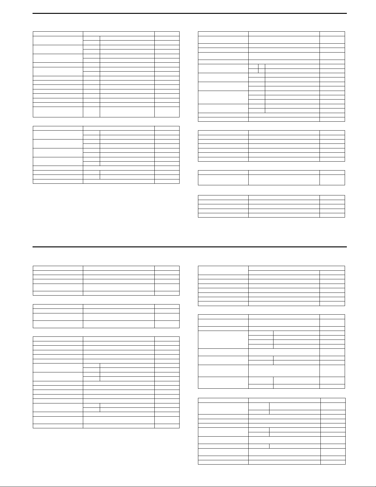
AN250
VALVE + VALVE GUIDE Unit: mm
Valve diam. IN. 28.3 —
Tappet clearance (when cold) IN. 0.08 – 0.13 —
Valve gui de to val ve stem clea rance
Valve guide I.D. IN. & EX. 5.000 – 5.012 —
Valve stem O.D. IN. 4.975 – 4.990 —
Valve stem deflection IN. & EX. — 0.35
Valve stem runout IN. & EX. — 0.05
Valve head thickness IN. & EX. — 0.5
Valve stem end length IN. & EX. — 1.7
Valve seat width IN. & EX. 0.9 – 1.1 —
Valve head radial runout IN. & EX. — 0.03
Valve spring free length IN. & EX. — 38.8
Valve spring tension
CAMSHAFT + C YLINDER HEAD Unit: mm
Cam height IN. 33.430 – 33.477 33.130
Camshaft journal oil clearance ¬22 0.032 – 0.066 0.15
Camsh aft jo urnal holder I. D. ¬22 22.012 – 22.025 —
Camsh aft jo urnal O.D. ¬22 21.959 – 21.980 —
Camshaft runout — 0.10
Rocker arm shaft I.D. IN. & EX. 12.000 – 12.018 —
Rocker arm shaft O.D. IN. & EX. 11.973 – 11.984 —
Cylinder head distortion — 0.05
ITEM STANDARD LIMIT
EX. 25.0 —
EX. 0.17 – 0.22 —
IN. 0.10 – 0.37 —
EX. 0.30 – 0.57 —
EX. 4.955 – 4.970 —
IN. & EX.
ITEM STANDARD LIMIT
EX. 33.500 – 33.547 33.200
¬17.5 0.028 – 0.059 0.15
¬17.5 17.512 – 17.525 —
¬17.5 17.466 – 17.484 —
182 – 210 N
(18.2 – 21.0 kgf)
at length 31.5 mm
—
CYLIN DER + PI STON + PISTO N RING Unit: mm
Compression pressure 1 250 – 1 650 kPa
Piston to cylinder clearance 0.04 – 0.05 0.120
Cylinder bore 73.000 – 73.015 73.090
Piston diam. 72.955 – 72.970
Cylinder distortion — 0.05
Piston ring free end gap 1s t R 9. 3 7.4
Piston ring end gap 1st 0.10 – 0.30 0.5
Piston ring to gr oove cle arance 1s t — 0.18
Piston ring groove width 1st 1. 01 – 1.0 4 —
Piston ring thickness 1st 0.97 – 0.99 —
Piston pin bore 19.002 – 19.008 19.030
Piston pin O.D. 18.996 – 19.000 19.980
CONROD + CRANKSHAFT Unit: mm
Conrod small end I.D. 19.006 – 19.014 19.04
Conrod deflection — 3.0
Conrod big end side clearance 0.10 – 0.75 1.0
Conrod big end width 21.95 – 22.00 —
Width between crankshaft webs 59.9 – 60.1 —
Crankshaft runout — 0.08
OIL PUMP
Oil pressure (at 60 °C) Above 80 kPa (0.8 kgf/cm
CLUTCH
Clutch wheel I.D. 135.0 – 135.2 135.5
Clutch shoe thickness 3.0 2.0
Engagement r/min 2 500 – 3 100 r/min —
Lock-up r/min 4 400 – 5 400 r/min —
ITEM STANDARD LIMIT
(12.5 – 16.5 kgf/cm
Measure at 15 mm from the skirtend.
2nd R 7.2 5.7
2nd 0.35 – 0.50 1.0
2nd — 0.15
2nd 1.01 – 1.04 —
Oil 2.01 – 2.03 —
2nd 0.97 – 0.99 —
ITEM STANDARD LIMIT
ITEM STANDARD LIMIT
Below1 60 kPa (1.6 kgf/cm
at 3 000 r/min
ITEM STANDARD LIMIT
2
)
2
)
2
)
1 050 kPa
(10.5 kgf/cm2)
72.880
—
Unit: mm
1
1/7 E-02, 19, 24, 38, 71
TRANSMISSION Unit: mm Except ratio
Reduction ratio 2.417 – 0.836 (variable change) —
Final reduction ratio 8.066 (44/16 × 44/15) —
Drive V-be lt width 22.6 21.6
Movable driven face spring free
length
Movable drive face roller O.D. 23.72 – 23.88 —
INJECTOR + FUEL PUMP + FUEL PRESSURE REGULATOR
Injector resistance 10 – 18 Ω at 20 °C —
Fuel pump discharge amount 35 ml and more
Fuel pressure regulator operating
set pressure
FI SENSORS
CKP se nsor re sist ance 180 – 2 80 Ω
CKP sensor peak voltage 4.5 V and more (When cranking)
IAP sensor input voltage 4.5 – 5.5 V
IAP sensor output voltage Approx. 2.6 V at idle speed
TP sensor input voltage 4.5 – 5.5 V
TP sensor resistance Closed Approx. 0.6 kΩ
TP sensor output voltage Closed Approx. 0.6 V
ECT se nsor in put voltage 4.5 – 5.5 V
ECT se nsor re sistance App rox. 1.14 kΩ at 4 0 °C
IAT sensor input voltage 4.5 – 5.5 V
IAT sensor resis tance A pprox . 1.14 kΩ at 40 ° C
TO sensor resistance 19.1 – 19.7 kΩ
TO sensor output voltage Normal 1.3 V and less
Injector voltage Battery voltage
Ignition coil primary peak voltage
PAIR solenoid valve resistance 20 – 24 Ω at 20 °C
ITEM STANDARD LIMIT
150 142.5
ITEM SPECIFICATION N OTE
2
For 10 sec, at 300 kPa (3.0 kgf/cm
Approx. 300 kPa (3.0 kgf/cm
ITEM SPECIFICATION N OTE
Opened Approx. 3.8 kΩ
Opened Approx. 3.8 V
Leaning 3.8 V and more
150 V and more (when cranking)
)
2
)—
—
: G, : BI
: W
: Ground
2/7 E-02, 19, 24, 38, 71
THROTTLE BODY
ITEM
ID N o. 14G 0 14G 1
Bore size 31.2 mm ←
Fast idle r/min 1 600 – 2 000 r/min ←
Idle r/min 1 500 ± 100 r/min ←
Idle air screw opening 2 and 1/8 turns out ←
IAC valve resistanc e Ap prox. 3 – 9 Ω at 20 – 24 °C ←
Throttle cable play 2.0 – 4.0 mm ←
THERMOSTAT + RADIATOR + FAN + COOLANT
Thermostat valve opening temperature
Thermostat valve lift Over 3.0 mm at 95 °C —
Engine coolant temperature sensor
resistance
Radiator cap valve opening pressure
Cooling fan thermo-switch operating temperature
Engine coolant type Use an anti-freeze/coolant compatible with alumi-
Engine coolant including reserve Reserve
ITEM ST ANDARD/SPECIFICATION LIMIT
20 °C Approx. 2.58 kΩ
40 °C Approx. 1.14 kΩ —
80 °C Approx. 0.28 kΩ
100 °C Approx. 0.16 kΩ —
ON Approx. 98 °C —
OFF Appro x. 92 °C —
num radiator, mixed with distilled water only, at the
ratio o f 50:50.
tank side
Engine side Approx. 1 300 ml —
SPECIFICATION
E-02, 19, 71, 24 E-38
Approx. 88 °C —
107.9 – 137.3 kPa
(1.1 – 1 .4 kgf/cm
2
)
Approx. 250 ml —
ELECTRICAL
Spark plug
Spark performance 8.0 mm and over at 1 atm.
CKP sensor resistance 180 – 288 Ω G – BI
CKP sensor peak voltage 4.5 V and more
Ignition coil resistance Primary 3 – 5 Ω
Ignition coil primary peak voltage
Generator coil resistance Charging 0.2 – 0.6 Ω Y – Y
Gener ator no -load voltage
(When cold)
Generator Max. output Approx. 375 W at 5 000 r/min
Regulated voltage 14.0 – 15.5 V at 5 000 r/min
ITEM STANDARD/SPECIFICATION NOTE
Type
Gap 0.6 – 0.7
Secondary 17 – 30 kΩ
55 V and more at 5 000 r/min
NGK: CR7E
DENSO: U22ESR-N
150 V and more
: G, : BI
: W
: Ground
—
—
Unit: mm
3/7 E-02, 19, 24, 38, 71
4/7 E-02, 19, 24, 38, 71
2
Starter relay resistance 3 – 6 Ω
Battery Type
Fuse size
WATTAGE Unit: W
Headlight HI 35 × 2 ←←←
Parkin g or positi on lig ht 5 5
Brake light/Taillight 21/5 × 2 ←←←
Turn signal light 21 ←←←
Front turn signal light/Position light 21/5
Rear turn signal light 21 ←←←
License light 5 ←←←
Instrument panel light 1.7 × 3 ←←←
Oil change indicator light 1.7 ←←←
FI indicator light 1.7 ←←←
Brake lock indicator light 1.7 ←←←
High beam indicator light 1.7 ←←←
Turn signal indicator light 1.7 × 2 ←←←
Trunk light 5 ←←←
Immobilizer indicator light LED LED
ITEM STANDARD/SPECIFICATION NOTE
FT12A-BS
STANDARD/SPECIFICATI ON
ITEM
designation
Capasity 12 V 36 kC (10 Ah) /10 HR
HI 15 A
Head-
light
LO 15 A
Meter 10 A
Ignition 10 A
Turn signal 15 A
Power source 10 A
Main 30 A
E-02, 19 E-24 E-38 E-71
LO 35 × 2 ←←←
BRAKE + WHEEL Unit: mm
Brake disc thickness Front 4.5 ± 0.2 4.0
Brake disc runout — 0.30
Master cylinder bore Front 11.000 – 11.043 —
Master cylinder piston diameter Front 10.957 – 10.984 —
Brake caliper cylinder bore Front 33.960 – 34.010/22.650 – 22.700 —
Brake caliper piston diameter Front 33.878 – 33.928/22.568 – 22.618 —
Wheel rim runout Axial — 2.0
Wheel axle runout Front — 0.25
Wheel rim size Front 13M/C × MT3.00 —
SUSPENSION Unit: mm
Front fork stroke 100 —
Front fork spring free length 330.4 324
Front fork oil type SUZUKI FORK OIL G-10 (#10) —
Front fork oil capacily (each leg) 284 ml —
Front fork oil level 96 —
Rear wh eel travel 100 —
Rear shock absorber spring
adjus ter
TIRE
Cold inflation tire pressure
Tire si ze Fron t 110/90 -13M/C 55 P —
Tire type Front BRIDGESTONE HOOP B03G —
Tire tread depth
(Recommended depth)
ITEM STANDARD LIMIT
Rear 5. 5 ± 0.2 5.0
Rear 14.000 – 14.043 —
Rear 13.957 – 13.984 —
Rear 25.400 – 25.450 —
Rear 25.318 – 25.368 —
Radial — 2 .0
Rear — 0.25
Rear 13M/C × MT3.50 —
ITEM STANDARD LIMIT
3rd —
ITEM STANDARD LIMIT
Solo riding
Dual r idin g
Front
Rear
Front
Rear
Rear 13 0/70- 13M/C 63P —
Rear — —
Front — 1.6 mm
Rear — 2.0 mm
175 kPa
(1.75 kgf/cm
200 kPa
(2.00 kgf/cm
175 kPa
(1.75 kgf/cm
225 kPa
(2.25 kgf/cm
2
)
2
)
2
)
2
)
—
—
—
—
5/7 E-02, 19, 24, 38, 71
FUEL + OIL
Fuel type Gasoline used should be graded 91 octane or
Fuel tank capacity Including
Engine oil type SAE 10W-40, API SF or SG
Engine oil capac ity Oil c hange 1. 9 L
Final gear oil capacity Oil change 190 ml
ITEM SPECIFICATION N OTE
higher. An unleaded gasoline is recommended.
reserve
Fuel meter
red zone
Filter change 2.0 L
Overhaul 2.3 L
Overhaul 200 ml
13.0 L
Approx. 3.0 L
6/7 E-02, 19, 24, 38, 71
7/7 E-02, 19, 24, 38, 71
AN400/S
VALVE + VALVE GUIDE Unit: mm (in)
Valve diam.
Tappet clearance (when cold)
Valve gui de to val ve stem
clear ance
Valve guide I.D.
Valve stem O.D.
Valve stem deflection
Valve stem runout
Valve head thickness
Valve stem end length
Valve seat width
Valve head radial runout
Valve spring free length
Valve spring tension
ITEM STANDARD LIMIT
IN.
EX.
IN.
EX.
IN.
EX.
IN. & EX.
IN.
EX.
IN. & EX. —
IN. & EX. —
IN. & EX. —
IN. & EX. —
IN. & EX.
IN. & EX. —
IN. & EX. —
IN. & EX.
(18.2 – 21.0 kgf, 40.1 – 46.3 lbs)
30.6
(1.20)
27.0
(1.06)
0.08 – 0.13
(0.003 – 0.005)
0.17 – 0.22
(0.007 – 0.009)
0.10 – 0.37
(0.004 – 0.015)
0.30 – 0.57
(0.012 – 0.022)
5.000 – 5.012
(0.1969 – 0.1973)
4.975 – 4.990
(0.1959 – 0.1965)
4.955 – 4.970
(0.1951 – 0.1957)
0.9 – 1.1
(0.035 – 0.043)
182 – 210 N
at length 31.5 mm (1.24 in)
—
—
—
—
—
—
—
—
—
0.35
(0.014)
0.05
(0.002)
0.5
(0.02)
1.7
(0.07)
—
0.03
(0.001)
38.8
(1.53)
—
CAMSHAFT + C YLINDER HEAD Unit: mm (in)
Cam height
Camshaft journal oil clearance
Camsh aft jo urnal holder I. D.
Camsh aft jo urnal O.D.
Camshaft runout
Rocker arm shaft I.D.
Rocker a rm shaft O.D.
Cylinder head distortion
CYLIN DER + PI STON + PISTO N RING Unit: mm (in)
Compression pressure 860 – 900 kPa
Piston to cylinder clearance 0.045 – 0.055
Cylinder bore 83.000 – 83.015
Piston diam. 82.950 – 82.965 (3.2657 – 3.2663)
Cylinder distortion
Piston ring free end gap
Piston ring end ga p
Piston ring to gr oove cle arance
ITEM STANDARD LIMIT
IN.
EX.
¬22
¬17.5
¬22
¬17.5
¬22
¬17.5
IN. & EX.
IN. & EX.
ITEM STANDARD LIMIT
(8.6 – 9.0 kgf/cm², 122 – 128 psi)
Measure at 15 mm (0.6 in) from the skirtend.
1st R Approx. 11.3 (0.44)
2nd R Approx. 7.7 (0.30)
1st
2nd
1st —
2nd —
33.430 – 33.477
(1.316 – 1.318)
33.300 – 33.347
(1.311 – 1.313)
0.032 – 0.066
(0.001 – 0.003)
0.028 – 0.059
(0.001 – 0.002)
22.012 – 22.025
(0.8666 – 0.8671)
17.512 – 17.525
(0.689 – 0.690)
21.959 – 21.980
(0.8645 – 0.8654)
17.466 – 17.484
(0.6876 – 0.6883)
—
12.000 – 12.018
(0.472 – 0.473)
11.973 – 11.984
(0.471 – 0.472)
—
(0.0018 – 0.0022)
(3.2677 – 3.2683)
—
0.20 – 0.35
(0.008 – 0.014)
0.35 – 0.50
(0.014 – 0.020)
33.130
(1.304)
33.000
(1.299)
0.15
(0.006)
0.15
(0.006)
—
—
—
—
0.10
(0.004)
—
—
0.05
(0.002)
616 kPa
(6.16 kgf/ cm², 88 psi)
0.120
(0.005)
83.085
(3.271)
82.880
(3.263)
0.05
(0.002)
9.0
(0.35)
6.2
(0.24)
0.70
(0.03)
1.0
(0.04)
0.18
(0.007)
0.15
(0.006)
3
AN400 E-02, 03, 19, 28, 33, 54
1/8
Piston ring groove width
Piston ring thick ness
Piston pin bore 20.002 – 20.008
Piston pin O.D. 19.992 – 20.000
CONROD + CRANKSHAFT Unit: mm (in)
Conrod small end I.D. 20.006 – 20.014
Conrod deflection
Conrod big end side clearance 0.10 – 0.75
Conrod big end width 21.95 – 22.00
Width between crankshaft webs 59.9 – 60.1
Crankshaft runout
OIL PUMP
Oil pressure (at 60 °C, 140 °F) Above 80 kPa (0.8 kgf/cm², 11 psi)
CLUTCH
Clutch wheel I.D. 150.0 – 150.2
Clutch shoe thickness 3.0
Engagement r/min 2 300 – 2 900 rpm —
Lock-up r/min 3 500 – 4 500 rpm —
ITEM STANDARD LIMIT
ITEM STANDARD LIMIT
ITEM STANDARD LIMIT
ITEM STANDARD LIMIT
1st
2nd
Oil
1st
2nd
Below 160 kPa (1.6 kgf/cm², 23 psi)
(0.0398 – 0.0406)
(0.0398 – 0.0406)
(0.0791 – 0.0799)
(0.0382 – 0.0390)
(0.0382 – 0.0390)
(0.7874 – 0.7877)
(0.7871 – 0.7874)
(0.7876 – 0.7880)
(0.004 – 0.030)
(0.864 – 0.866)
(2.358 – 2.366)
at 3 000 r/min
(5.906 – 5.913)
(0.12)
AN400S E-02, 03, 19, 28, 33
1.01 – 1.03
1.01 – 1.03
2.01 – 2.03
0.97 – 0.99
0.97 – 0.99
—
—
—
—
—
—
—
20.030
(0.789)
19.980
(0.787)
20.040
(0.789)
3.0
(0.12)
1.0
(0.04)
—
—
0.08
(0.003)
—
Unit: mm (in)
150.5
(5.925)
2.0
(0.08)
AN400 E-02, 03, 19, 28, 33, 54
2/8
TRANSMISSION Unit: mm (in) Except ratio
Reduction ratio 2.203 – 0.854 (Variable change) —
Final reduction ratio 6.168 (31/14 × 39/14) —
Drive V-be lt width 21.8 5
Movable driven face spring free
length
Movable drive face roller O.D. 23.72 – 23.88
Drive/Driven face wear
INJECTOR + FUEL PUMP + FUEL PRESSURE REGULATOR
Injector resistance 10 – 18 Ω at 20 °C (68 °F) —
Fuel pump discharge amount 35 ml and more
Fuel pressure regulator operating
set pressure
FI SENSORS
CKP se nsor re sist ance 180 – 2 80 Ω
CKP sensor peak voltage 4.5 V and more (When cranking)
IAP sensor input voltage 4.5 – 5.5 V
IAP sensor output voltage Approx. 2.6 V at idle speed
TP sensor input voltage 4.5 – 5.5 V
TP sensor resistance Closed Approx. 0.6 kΩ
TP sensor output voltage Closed Approx. 0.6 V
ECT se nsor in put voltage 4.5 – 5.5 V
ECT se nsor re sistance A pprox. 1.1 4 kΩ at 40 °C (104 °F)
IAT sensor input voltage 4.5 – 5.5 V
IAT sensor resis tance A pprox. 1. 14 kΩ at 40 °C (104 °F)
TO sensor resistance 19.1 – 19.7 kΩ
TO sensor output voltage Normal 1.3 V and less
Injector voltage Battery voltage
Ignition coil primary peak voltage
PAIR solenoid valve resistance 20 – 24 Ω at 20 °C (68 °F)
HO2 sensor resistance 11.5 – 14.5 Ω at 23 °C (73.4 °F)
HO2 sensor output voltage Idle speed 0.3 V and less
ITEM STANDARD LIMIT
(0.93 – 0.94)
ITEM SPECIFICATION N OTE
For 10 sec, at 300 kPa (3.0 kgf/cm², 43 psi)
Approx. 300 kPa (3.0 kgf/cm², 43 psi) —
ITEM SPECIFICATION N OTE
Opened Approx. 3.8 kΩ
Opened Approx. 3.8 V
Leaning 3.8 V and more
150 V and more (when cranking)
3 000 r/min 0.7 V and more
AN400S E-02, 03, 19, 28, 33
(0.86)
125
(4.92)
—
20.85
(0.82)
118.7
(4.67)
—
0.4
(0.02)
—
: G, : BI
: W
: Ground
AN400 E-02, 03, 19, 28, 33, 54
3/8
AN400S E-02, 03, 19, 28, 33
4/8
AN400 E-02, 03, 19, 28, 33, 54
AN400S E-02, 03, 19, 28, 33
4
THROTTLE BODY
ITEM
I.D. No. 15G0 15G1
Bore size 37.2 mm (1.46 in) ←
Fast idle r/min 1 600 – 2 000 r/min ←
Idle r/min 1 400 ± 100 r/min ←
Idle air screw opening 2 turns out ←
IAC valve resistance Approx. 3 – 9 Ω at 20 – 24 °C (68 – 75 °F) ←
Throttle cable play 2.0 – 4.0 mm (0.08 – 0.16 in) ←
THERMOSTAT + RADIATOR + FAN + COOLANT
Thermostat valve opening temperature
Thermostat valve lift Over 3.0 mm at 95 °C (203 °F) —
Engine coolant temperature sensor
resistance
Radiator cap valve opening pressure
Cooling fan thermo-switch operating temperature
Engine coolant type Use an anti-freeze/coolant compatible with alumi-
Engine coolant in cluding re serve Reser ve
ELECTRICAL
Spark plug
Spark performance 8.0 mm (0.31 in) and over at 1 atm.
CKP sensor resistance 180 – 288 Ω G – BI
CKP sensor peak voltage
Ignition coil resistance Primary 3 – 5 Ω
Ignition coil primary peak voltage
ITEM ST ANDARD/SPECIFICATION LIMIT
ITEM ST ANDARD/SPECIFICATION NOTE
Approx. 82 °C (180 °F) ± 1.5 —
20 °C
(68 °F)
40 °C
(104 °F)
80 °C
(176 °F)
100 °C
(212 °F)
(1.1 – 1 .4 kgf/cm² , 16 – 20 psi )
ON 93 – 103 °C (199 – 217 °F) —
OFF 87 – 97 °C (189 – 207 °F) —
num radiator, mixed with distilled water only, at the
ratio of 50:50.
tank side
Engine
Approx. 1 300 ml (4 3.9/45.8 US /Imp oz) —
side
Type
Gap
Secondary 17 – 30 kΩ
SPECIFICATION
E-02, 03, 19, 28, 54 E-33
Approx. 2.58 kΩ —
Approx. 1.14 kΩ —
Approx. 0.28 kΩ —
Approx. 0.16 kΩ —
107.9 – 137.3 kPa
Approx. 250 ml (8.5/8.8 US/Imp oz) —
Unit: mm (in)
NGK: CR7E
DENSO: U22ESR- N
0.7 – 0.8
(0.28 – 0.03 in)
4.5 V and more
150 and more
5/8
AN400 E-02, 03, 19, 28, 33, 54
AN400S E-02, 03, 19, 28, 33
: G/W
: BI
: W
: Ground
Generator coil resistance Charging 0.2 – 0.6 Ω Y – Y
Gener ator no -load voltage
(When cold)
Generator Max. output Approx. 375 W at 5 000 r/min
Regulated voltage 14.0 – 15.5 V at 5 000 r/min
Starter relay resistance 3 – 6 Ω
Battery Type
Fuse size
WATTAGE Unit: W
Headlight HI 35 × 2 ←
—
—
Parkin g or positi on lig ht 5
Brake light/Taillight 21/5 × 2 ←
Turn signal light 21 × 4 ←
License light 5 ←
Instrument panel light 1.7 × 3 ←
Oil change indicator light 1.7 ←
FI indicator light 1.7 ←
Brake-lock indicator light 1.7 ←
High beam indicator light 1.7 ←
Turn signal indicator light 1.7 × 2 ←
Trunk light 5 ←
Immobilizer indicator light LED
ITEM ST ANDARD/SPECIFICATION NOTE
55 V and more at 5 000 r/min
FT12A-BS
STANDARD/SPECIFICATI ON
AN400 E-02, 03, 19, 28, 33, 54
AN400S E-02, 03, 19, 28, 33
ITEM
designation
Capasity 12 V 36 kC (10 Ah) /10 HR
HI 10 A
Headlight
LO 10 A
Meter 10 A
Ignition 10 A
Turn signal 15 A
Power source 10 A
Main 30 A
E-02, 19, 54 E-03, 28, 33
LO 35 × 2 ←
6/8
BRAKE + WHEEL Unit: mm (in)
Brake disc thickness
Brake disc runout
Master cylinder bore
Master cylinder piston diameter
Brake caliper cylinder bore
Brake caliper piston diameter
Wheel rim runout
Wheel axle runout
Wheel rim size Front 13M/C × MT3.00 —
SUSPENSION Unit: mm (in)
Front fork stroke 100 (3.94) —
Front fork spring free length
Front fork oil type SUZUKI FORK OIL G-10 (#10) —
Front fork oil capacily (each leg) 284 ml —
Front fork oil level 96 (3.78) —
Rear wheel travel 100 (3.94) —
Rear shock absorber spring
adjus ter
ITEM STANDARD LIMIT
Front
Rear
Front
Rear
Front
Rear
Front
Rear
Front
Rear
Axial —
Radial —
Front —
Rear —
Rear 13M/C × MT3.50 —
ITEM STANDARD LIMIT
Standard
Range 17 turns (34 clicks) —
4.5 ± 0. 2
(0.18 ± 0.008)
5.5 ± 0. 2
(0.22 ± 0.008)
—
11.000 – 11.043
(0.433 – 0.435)
14.000 – 14.043
(0.551 – 0.553)
10.957 – 10.984
(0.431 – 0.432)
13.957 – 13.984
(0.549 – 0.551)
33.960 – 34.010/22.650 – 22.700
(1.337 – 1.339/0.892 – 0.894)
25.400 – 25.450
(1.000 – 1.002)
33.878 – 33.928/22.568 – 22.618
(1.334 – 1.336/0.889 – 0.890)
25.318 – 25.368
(0.997 – 0.999)
330.4 (13.01)
4 and 1/2 turns out
from softest position (9 clicks)
4.0
(0.16)
4.5
(0.18)
0.30
(0.01)
—
—
—
—
—
—
—
—
2.0
(0.08)
2.0
(0.08)
0.25
(0.01)
0.25
(0.01)
324
(12.76)
—
TIRE
Cold inflation tire pressure
Tire si ze Fron t 110/ 90-13 M /C 55P —
Tire type Front BRIDGESTONE HOOP B03G —
Tire tread depth
(Recommended depth)
FUEL + OIL
Fuel type Gasoline used should be graded 91 octane or
Fuel tank capacity Including
Engine oil type SAE 10W-40, API SF or SG
Engine oil capac ity
Final gear oil capacity
ITEM STANDARD LIMIT
ITEM SPECIFICATION N OTE
Front
Solo
riding
Rear
Front
Dual
riding
Rear
Rear 13 0/70-13 M /C 63P —
Rear BRIDGESTONE HOOP B02G —
Front —
Rear —
higher. An unleaded gasoline is recommended.
reserve
Fuel meter
red zone
Oil change
Filter
change
Overhaul
Oil change
Overhaul
175 kPa
(1.75 kgf/cm², 25 psi)
200 kPa
(2.00 kgf/cm², 28 psi)
175 kPa
(1.75 kgf/cm², 25 psi)
280 kPa
(2.80 kgf/cm², 40 psi)
13.0 L
(3.4/2.9 US/Imp gal)
Approx. 3.0 L (3.2/2.6 US/Imp qt)
1.9 L
(2.0/1.7 US/Imp qt)
2.0 L
(2.1/1.8 US/Imp qt)
2.3 L
(2.4/2.0 US/Imp qt)
190 ml
(6.4/6.7 US/Imp oz)
200 ml
(6.8/7.0 US/Imp oz)
1.6 mm
(0.06 in)
2.0 mm
(0.08 in)
—
—
—
—
AN400 E-02, 03, 19, 28, 33, 54
7/8
AN400S E-02, 03, 19, 28, 33
8/8
AN400 E-02, 03, 19, 28, 33, 54
AN400S E-02, 03, 19, 28, 33
AN650
VALVE + GUIDE Unit: mm (in)
Valve diam.
Tappet clearance (when cold)
Valve gui de to val ve stem
clear ance
Valve guide I.D.
Valve stem O.D.
Valve stem deflection
Valve stem runout
Valve head thickness
Valve seat width
Valve head radial runout
Valve spring free length (IN. & EX.)
Valve spring tension (IN. & EX.)
ITEM STANDARD LIMIT
IN.
EX.
IN.
EX.
IN.
EX.
IN. & EX.
IN.
EX.
IN. & EX. —
IN. & EX. —
IN. & EX. —
IN. & EX.
IN. & EX. —
IN. & EX. —
IN. & EX.
(13.6 – 15.6 kgf, 30.0 – 34.4 lbs)
29.5
(1.16)
25.0
(0.98)
0.10 – 0.20
(0.0039 – 0.0079)
0.20 – 0.30
(0.0079 – 0.0118)
0.010 – 0.040
(0.0004 – 0.0016)
0.030 – 0.060
(0.0012 – 0.0024)
4.500 – 4.515
(0.1772 – 0.1778)
4.475 – 4.490
(0.1762 – 0.1768)
4.455 – 4.470
(0.1754 – 0.1760)
0.9 – 1.1
(0.035 – 0.043)
136 – 156 N
at length 33.4 mm (1.31 in)
—
—
—
—
—
—
—
—
—
0.35
(0.014)
0.05
(0.002)
0.5
(0.02)
—
0.03
(0.001)
40.6
(1.60)
—
CAMSHAFT + C YLINDER HEAD Unit: mm (in)
Cam height
Camshaft journal oil clearance
Camsh aft jo urnal holder I. D.
Camsh aft jo urnal O.D.
Camshaft runout
Cam chain pin (at arrow “3”) 15th pin —
Cylinder head distortion
CYLIN DER + PI STON + PISTO N RING Unit: mm (in)
Compression pressure 1 500 – 1 900 kPa
Compr ession pres sure diffe rence
Piston to cylinder clearance 0.045 – 0.055
Cylinder bore 75.500 – 75.515
Piston diam. 75.470 – 75 .485
Cylinder distortion
Piston ring free end gap
Piston ring end ga p
Piston ring to gr oove cle arance
Piston ring groove width
ITEM STANDARD LIMIT
IN.
EX.
IN. & EX.
IN. & EX.
IN. & EX.
IN. & EX. —
ITEM STANDARD LIMIT
(15.0 – 19.0 kgf/cm
Measure at 15 mm (0.6 in) from the skirt end.
1st R Approx. 11.6 (0.46)
2nd RN Approx. 8.6 (0.34)
1st
2nd
1st —
2nd —
1st
2nd
Oil
35.38 – 35.43
(1.393 – 1.395)
33.98 – 34.03
(1.338 – 1.340)
0.032– 0.066
(0.0013 – 0.0026)
24.012 – 24.025
(0.9454 – 0.9459)
23.959 – 23.980
(0.9433 – 0.9441)
—
2
, 213 – 270 psi)
—
(0.0018 – 0.0022)
(2.9724 – 2.9730)
(2.9705 – 2.9711)
—
0.06 – 0.18
(0.002 – 0.005)
0.06 – 0.18
(0.002 – 0.005)
1.01 – 1.03
(0.040 – 0.041)
1.01 – 1.03
(0.040 – 0.041)
2.01 – 2.03
(0.079 – 0.080)
35.10
(1.382)
33.70
(1.327)
0.150
(0.0059)
—
—
0.10
(0.004)
0.10
(0.004)
1 200 kPa
(12 kgf/cm2, 171 psi)
200 kPa
(2.0 kgf/cm
0.120
(0.0047)
Nicks or
scratches
75.380
(2.9677)
0.10
(0.004)
9.3
(0.37)
6.9
(0.27)
0.50
(0.020)
0.50
(0.020)
0.180
(0.007)
0.150
(0.006)
—
—
—
2
, 28 psi)
5
1/9 E-02, 03, 19, 24, 28, 33
Piston ring thick ness
Piston pin bore 1 6.002 – 16.008
Piston pin O.D. 15.995 – 16.000
CONROD + CRANKSHAFT Unit: mm (in)
Conrod small end I.D. 16.010 – 16.018
Conrod big end side clearance 0.10 – 0.20
Conrod big end width 19.950 – 20.000
Crank pin width 20.100 – 20.150
Conrod big end oil clearance 0.032 – 0.056
Crank pin O.D. 44.976 – 45.000
Crankshaft journal oil clearance 0.018 – 0.045
Crankshaft journal O.D. 47.985 – 48.000
Crankshaft thrust bearing thickness 2.025 – 2.175
Cranks haft thrus t clearanc e 0.10 – 0.1 5
Crankshaft runout
OIL PUMP
Oil pressure (at 60 °C, 140 °F) Above 350 kPa (3.5 kgf/cm
ITEM STANDARD LIMIT
1st
2nd
ITEM STANDARD LIMIT
ITEM STANDARD LIMIT
Below 550 kPa (5.5 kgf/cm
0.97 – 0.99
(0.038 – 0.039)
0.97 – 0.99
(0.038 – 0.039)
(0.6300 – 0.6302)
(0.6297 – 0.6299)
(0.6303 – 0.6306)
(0.004 – 0.008)
(0.7854 – 0.7874)
(0.7913 – 0.7933)
(0.0013 – 0.0022)
(1.7707 – 1.7717)
(0.0007 – 0.0018)
(1.8892 – 1.8898)
(0.0797 – 0.0856)
(0.0039 – 0.0059)
—
at 3 000 r/min
2
, 49.8 psi)
2
, 78.2 psi)
—
—
16.030
(0.6311)
15.980
(0.6291)
16.040
(0.6315)
0.30
(0.012)
—
—
0.080
(0.0031)
—
0.080
(0.0031)
—
—
—
0.05
(0.002)
—
2/9 E-02, 03, 19, 24, 28, 33
CLUTCH Unit: mm (in)
Drive plate thickness 2.92 – 3.08
Drive p late claw wi dth 13. 85 – 13 .96
Driven plate No. 2 thickness 2.42 – 2.58
Driven plate distortion
Clutch spring free length 13.9
Clutch plate concaved washer
heigh t
Clutch engagement 1 500 – 2 100 r/min —
Clutch lock-up 3 200 – 3 800 r/min —
INJECTOR + FUEL PUMP + FUEL PRESSURE REGULATOR
Injector resistance 11 – 13 Ω at 20 °C (68 °F) —
Fuel pump discharge amount More than 0.9 L (0.95/0.79 US/Imp qt)
Fuel pressure regulator operating
set pressure
FI/CVT-SENSORS
CMP sensor resistance 0.9 – 1.7 kΩ
CMP sensor peak voltage More than 0.5 V (When cranking) : B/Y, : Br
CKP sensor resistance 150 – 300 Ω
CKP sensor peak voltage More than 2.0 V (When cranking) : Bl, : G
IAP sensor input voltage 4.5 – 5.5 V
IAP sensor output voltage Approx. 2.6 V at idle speed
TP sensor input voltage 4.5 – 5.5 V
TP sensor resistance Closed Approx. 1.1 kΩ
TP sensor output voltage Closed Approx. 1.1 V
ECT se nsor in put voltage 4.5 – 5.5 V
ECT sensor resistance Approx. 2.45 kΩ at 20 °C (68 °F)
IAT sensor input voltage 4.5 – 5.5 V
IAT sensor resistance Approx. 2.45 kΩ at 20 °C (68 °F)
AP sens or input vol tage 4.5 – 5.5 V
AP sensor output voltage Approx. 3.6 V at 100 kPa (760 mmHg)
TO sensor resistance 19.1 – 19.7 kΩ
TO sensor output voltage Normal 0.4 – 1.4 V
Injector voltage Battery voltage
ITEM STANDARD LIMIT
(0.115 – 0.121)
(0.545 – 0.550)
(0.095 – 0.102)
—
(0.547)
3.2
(0.126)
ITEM SPECIFICATION NOTE
2
For 30 sec. at 300 kPa (3.0 kgf/cm
Approx. 300 kPa (3.0 kgf/cm
ITEM SPECIFICATION N OTE
Opened Approx. 4.2 kΩ
Opened Approx. 4.3 V
Leaning 3.7 – 4.4 V : B, : B/Br
, 43 psi)
2
, 43 psi) —
2.62
(0.103)
13.05
(0.514)
2.27
(0.089)
0.10
(0.004)
13.2
(0.520)
3.1
(0.12)
—
: B, : B/Br
3/9 E-02, 03, 19, 24, 28, 33
4/9 E-02, 03, 19, 24, 28, 33
6
Ignition coil primary peak voltage
HO2 sensor resistance 4 – 5 Ω at 23 °C (73.4 °F)
HO2 sensor output voltage Idle speed Less than 0.4 V
PAIR solenoid valve resistance 20 – 24 Ω at 20 °C (68 °F)
CVT primary pulley position sensor Compressed 1.9 – 2.3 kΩ
CVT primary pulley position sensor
output voltage
CVT secondary pulley revolution
sensor resistance
CVT secondary pulley revolution
sensor peak voltage
THROTTLE BODY
I.D. No. 10G0
Bore size 32 mm (1.2 6 in)
Fast idle r/min 1 300 – 1 600 r/min
Idle r/min 1 200 ± 100 r/min
Synchronizing screw opening 1 and 1/2 turns out
IAC valve resistance Approx. 4 Ω at 20 – 24 °C (68 – 75 °F)
Throttle cable play 2.0 – 4.0 mm
THERMOSTAT + RADIATOR + FAN + COOLANT
Thermostat valve opening temperature
Thermostat valve lift Over 8.0 mm (0.3 in) at 100 °C (212 °F) —
Engine coolant temperature sensor
resistance
Radiator cap valve opening pressure
Eclectic fan thermo-switch operating temperature
Engine coolant type Use an anti-freeze/coolant compatible with alumi-
ITEM SPECIFICATION N OTE
More than 80 V (When cranking)
3 000 r/min More than 0.6 V
Extended 0.2 – 1.0 kΩ
st
: Idle speed Approx. 3.3 V
1
rd
: 3 000 r/min Approx. 1.3 V
3
th
: 3 000 r/min Approx. 0.5 V
5
400 – 600 Ω
More than 5 V at idle speed
ITEM SPECIFICATION
(0.08 – 0.16 in)
ITEM ST ANDARD/SPECIFICATION LIMIT
Approx. 88 °C (190 °F) —
20 °C (68 °F) Approx. 2.45 kΩ —
50 °C (122 °F) Approx. 0.811 kΩ —
80 °C (176 °F) Approx. 0.318 kΩ —
110 °C (230 °F) Approx. 0.142 kΩ —
110 kPa ( 1.1 kgf /cm²) —
ON 93 – 103 °C (199 – 217 °F) —
OFF 87 – 97 °C (188 – 206 °F) —
num radiator, mixed with distilled water only, at the
ratio of 50:50.
: W/Bl,
#1
: Ground
#2 : B/Y,
: Ground
: Y, : W
Engine coolant including reserve Reverse
ELECTRICAL Unit: mm (in)
Firing order 1·2
Spark plug
Spark performance Over 8.0 (0.3) at 1 atm.
CKP sensor peak voltage More than 2.0 V
Ignition coil resistance Primary 0.8 – 2.5 Ω
Ignition coil primary peak voltage
Generator coil resistance CKP sensor 150 – 300 Ω G – BI
Gener ator no -load voltage
(When cold)
Generator Max. output Approx. 500 W at 5 000 r/min
Regulated voltage 14.0 – 15.5 V at 5 000 r/min
Starter relay resistance 3 – 6 Ω
Battery Type
Fuse size
ITEM ST ANDARD/SPECIFICATION LIMIT
tank side
Engine side
Approx. 250 ml
(0.264/0.220 US/Imp qt)
Approx. 1 350 ml
(1.427/1.188 US/Imp qt)
—
—
ITEM STD/SPEC. NOTE
Type
Gap
NGK: CR8E
DENSO: U24ESR-N
0.7 – 0 .8
(0.028 – 0.031)
: Bl, :G
Secondary 8 – 18 kΩ
Mor e than 80 V
#1 : W/Bl,
: Ground
#2 : B/Y,
: Ground
Charging 0.1 – 1.0 Ω Y – Y
More than 50 V at 5 000 r/min
designation
Capac ity 12 V 43. 2 kC (1 2 Ah)/ 10 HR
LO
Head-
light
HI 15 A
Fuel pump 10 A
Ignition 15 A
Turn signal 15 A
Fan m otor 1 5 A
Main 40 A
CVT 40 A
Power
source
FTX14-BS
15 A.......... E-03, 24, 28, 33
10 A.......... E-02, 19
10 A
—
5/9 E-02, 03, 19, 24, 28, 33
WATTAGE Unit: W
ITEM
Headlight HI 60 + 55 60 × 2
Parkin g or positi on lig ht 5 × 2
Brake light/Taillight 21/5 × 2 ←
Turn signal light 21 × 4 ←
License light 5 ←
Instrument panel light 1.4 × 2 ←
Engine coolant temp. indicator light 1.4 ←
FI indicator light 1.4 ←
Engine oil pressure indicator light 1.4 ←
Brake-lock indicator light 1.4 ←
High beam indicator light 1.4 ←
Turn signal indicator light 1.4 × 2 ←
Power mode indicator light 1.4 ←
Drive indicator light 1.4 ←
Gear position indicator light 1.4 × 5 ←
Trunk light 5 ←
Immobilizer indicator light LED
Over drive indicator light 1.4 ←
LO 55 55 × 2
E-02, 19 E-03, 24, 28, 33
STD/SPEC.
BRAKE + WHEEL Unit: mm (in)
Brake disc thickness
Brake disc runout
Master cylinder bore
Master cylinder piston diameter
Brake caliper cylinder bore
Brake caliper piston diameter
Brake fluid type DOT 4 —
ITEM STANDARD LIMIT
Front
Rear
Front
Rear
Front
Rear
Front
Rear
Front
Rear
4.5 ± 0. 2
(0.1 77 ± 0.008)
5.5 ± 0. 2
(0.2 17 ± 0.008)
—
12.700 – 12.743
(0.5000 – 0.5017)
12.700 – 12.743
(0.5000 – 0.5017)
12.657 – 12.684
(0.4983 – 0.4994)
12.657 – 12.684
(0.4983 – 0.4994)
25.400 – 25.450
(1.0000 – 1.0020)
27.000 – 27.050
(1.0630 – 1.0650)
25.318 – 25.368
(0.9968 – 0.9987)
26.918 – 26.968
(1.0598 – 1.0617)
4.0
(0.16)
5.0
(0.20)
0.30
(0.012)
—
—
—
—
—
—
—
—
6/9 E-02, 03, 19, 24, 28, 33
Wheel rim runout
Wheel axle runout
Wheel rim size Front 15 M/C × MT3.50 —
ITEM STANDARD LIMIT
Axial —
Radial —
Front —
Rear —
2.0
(0.08)
2.0
(0.08)
0.25
(0.010)
0.25
(0.010)
Rear 14 M/C × MT4.50 —
SUSPENSION Unit: mm (in)
Front fork stroke 110
Front fork spring free length
Front fork oil type SUZUKI FORK OIL G-10 (#10) or
Front fork oil capacity (each leg) 458 ml —
Front fork oil level 151
Front fork inner tube diam. 41
Rear wheel travel 100
Rear shock absorber spring
adjus ter
ITEM STANDARD LIMIT
(4.3)
—
an equivalent fork oil
(5.9)
—
341
(13.4)
—
—
(1.61)
(3.9)
—
2nd —
TIRE
Cold inflation tire pressure
Tire size Front 120/70R15M/C 56H —
Tire type Front BRIDGESTONE TH01F —
Tire tread depth
(Recommended depth)
ITEM STAN DARD LIMIT
Solo
riding
Dual
riding
Front
Rear
Front
Rear
225 kPa
(2.25 kgf/cm
250 kPa
(2.50 kgf/cm
225 kPa
(2.25 kgf/cm
280 kPa
(2.80 kgf/cm
2
, 33 psi)
2
, 36 psi)
2
, 33 psi)
2
, 41 psi)
—
—
—
—
Rear 160/60R14M/C 65H —
Rear BRIDGESTONE TH01R —
Front —
Rear —
1.6 mm
(0.06 in)
2.0 mm
(0.08 in)
7/9 E-02, 03, 19, 24, 28, 33
8/9 E-02, 03, 19, 24, 28, 33
7
FUEL + OI L
Fuel type Use only unleaded gasoline of at least 87 pump
Fuel tank capacity Including
Engine oil and transmission oil type SAE 10W-40, API SF/SG or SH/SJ with JASO MA
Engine oil capac ity
Transmission oil capacity
Final gear oil type Hypoid gear oil SAE #90 API grade GL-5
Final gear oil capacity
ITEM SPECIFICATION NOTE
octane (R/2 + M/2) or 91 octane or higher rated by
the research method.
Gasoline containing MTBE (Methyl Tertiary Butyl
Ether), less than 10% ethanol, or less than 5%
methanol with appropriate cosolvents and corro-
sion inhibitor is permissible.
Gasoline used should be graded 91 octane or
higher. An unleaded gasoline is recommended.
reserve
Fuel meter
mark
flickering
Fuel meter
mark and
LCD
flickering
Oil change
Filter change
Overhaul
Oil change
Overhaul
Oil change
Overhaul
15.0 L (4.0/3.3 US/lmp gal)
Approx . 3.0 L (0.79 /0.66 US/l mp gal)
Approx . 1.5 L (0.40 /0.33 US/l mp gal)
2.6 L
(2.7 /2.3 US/l mp qt)
2.9 L
(3.1 /2.6 US/l mp qt)
3.4 L
(3.6/3.0 US/lmp qt)
360 ml
(12.2 /12.7 US/l mp oz)
400 ml
(13.5 /14.1 US/l mp oz)
300 ml
(10.1 /10.6 US/l mp oz)
430 ml
(14.5 /15.1 US/l mp oz)
E-03, 28, 33
The others
9/9 E-02, 03, 19, 24, 28, 33
AN650A
VALVE + GUIDE Unit: mm (in)
Valve diam.
Tappet clearance (when cold)
Valve gui de to val ve stem
clear ance
Valve guide I.D.
Valve stem O.D.
Valve stem deflection
Valve stem runout
Valve head thickness
Valve seat width
Valve head radial runout
Valve spring free length (IN. & EX.)
Valve spring tension (IN. & EX.)
ITEM STANDARD LIMIT
IN.
EX.
IN.
EX.
IN.
EX.
IN. & EX.
IN.
EX.
IN. & EX. —
IN. & EX. —
IN. & EX. —
IN. & EX.
IN. & EX. —
IN. & EX. —
IN. & EX.
(13.6 – 15.6 kgf, 30.0 – 34.4 lbs)
29.5
(1.16)
25.0
(0.98)
0.10 – 0.20
(0.0039 – 0.0079)
0.20 – 0.30
(0.0079 – 0.0118)
0.010 – 0.040
(0.0004 – 0.0016)
0.030 – 0.060
(0.0012 – 0.0024)
4.500 – 4.515
(0.1772 – 0.1778)
4.475 – 4.490
(0.1762 – 0.1768)
4.455 – 4.470
(0.1754 – 0.1760)
0.9 – 1.1
(0.035 – 0.043)
136 – 156 N
at length 33.4 mm (1.31 in)
—
—
—
—
—
—
—
—
—
0.35
(0.014)
0.05
(0.002)
0.5
(0.02)
—
0.03
(0.001)
40.6
(1.60)
—
CAMSHAFT + C YLINDER HEAD Unit: mm (in)
Cam height
Camshaft journal oil clearance
Camsh aft jo urnal holder I. D.
Camsh aft jo urnal O.D.
Camshaft runout
Cam chain pin (at arrow “3”) 15th pin —
Cylinder head distortion
CYLIN DER + PI STON + PISTO N RING Unit: mm (in)
Compression pressure 1 500 – 1 900 kPa
Compr ession pres sure diffe rence
Piston to cylinder clearance 0.045 – 0.055
Cylinder bore 75.500 – 75.515
Piston diam. 75.470 – 75 .485
Cylinder distortion
Piston ring free end gap
Piston ring end ga p
Piston ring to gr oove cle arance
Piston ring groove width
ITEM STANDARD LIMIT
IN.
EX.
IN. & EX.
IN. & EX.
IN. & EX.
IN. & EX. —
ITEM STANDARD LIMIT
(15.0 – 19.0 kgf/cm
Measure at 15 mm (0.6 in) from the skirt end.
1st R Approx. 11.6 (0.46)
2nd RN Approx. 8.6 (0.34)
1st
2nd
1st —
2nd —
1st
2nd
Oil
35.38 – 35.43
(1.393 – 1.395)
33.98 – 34.03
(1.338 – 1.340)
0.032– 0.066
(0.0013 – 0.0026)
24.012 – 24.025
(0.9454 – 0.9459)
23.959 – 23.980
(0.9433 – 0.9441)
—
2
, 213 – 270 psi)
—
(0.0018 – 0.0022)
(2.9724 – 2.9730)
(2.9705 – 2.9711)
—
0.06 – 0.18
(0.002 – 0.005)
0.06 – 0.18
(0.002 – 0.005)
1.01 – 1.03
(0.040 – 0.041)
1.01 – 1.03
(0.040 – 0.041)
2.01 – 2.03
(0.079 – 0.080)
35.10
(1.382)
33.70
(1.327)
0.150
(0.0059)
—
—
0.10
(0.004)
0.10
(0.004)
1 200 kPa
(12 kgf/cm2, 171 psi)
200 kPa
(2.0 kgf/cm
0.120
(0.0047)
Nicks or
scratches
75.380
(2.9677)
0.10
(0.004)
9.3
(0.37)
6.9
(0.27)
0.50
(0.020)
0.50
(0.020)
0.180
(0.007)
0.150
(0.006)
—
—
—
2
, 28 psi)
1/9 E-02, 19
2/9 E-02, 19
8
Piston ring thick ness
Piston pin bore 1 6.002 – 16.008
Piston pin O.D. 15.995 – 16.000
CONROD + CRANKSHAFT Unit: mm (in)
Conrod small end I.D. 16.010 – 16.018
Conrod big end side clearance 0.10 – 0.20
Conrod big end width 19.950 – 20.000
Crank pin width 20.100 – 20.150
Conrod big end oil clearance 0.032 – 0.056
Crank pin O.D. 44.976 – 45.000
Crankshaft journal oil clearance 0.018 – 0.045
Crankshaft journal O.D. 47.985 – 48.000
Crankshaft thrust bearing thickness 2.025 – 2.175
Cranks haft thrus t clearanc e 0.10 – 0.1 5
Crankshaft runout
OIL PUMP
Oil pressure (at 60 °C, 140 °F) Above 350 kPa (3.5 kgf/cm
ITEM STANDARD LIMIT
1st
2nd
ITEM STANDARD LIMIT
ITEM STANDARD LIMIT
Below 550 kPa (5.5 kgf/cm
0.97 – 0.99
(0.038 – 0.039)
0.97 – 0.99
(0.038 – 0.039)
(0.6300 – 0.6302)
(0.6297 – 0.6299)
(0.6303 – 0.6306)
(0.004 – 0.008)
(0.7854 – 0.7874)
(0.7913 – 0.7933)
(0.0013 – 0.0022)
(1.7707 – 1.7717)
(0.0007 – 0.0018)
(1.8892 – 1.8898)
(0.0797 – 0.0856)
(0.0039 – 0.0059)
—
at 3 000 r/min
2
, 49.8 psi)
2
, 78.2 psi)
—
—
16.030
(0.6311)
15.980
(0.6291)
16.040
(0.6315)
0.30
(0.012)
—
—
0.080
(0.0031)
—
0.080
(0.0031)
—
—
—
0.05
(0.002)
—
CLUTCH Unit: mm (in)
Drive plate thickness 2.92 – 3.08
Drive p late claw wi dth 13. 85 – 13 .96
Driven plate No. 2 thickness 2.42 – 2.58
Driven plate distortion
Clutch spring free length 13.9
Clutch plate concaved washer
heigh t
Clutch engagement 1 500 – 2 100 r/min —
Clutch lock-up 3 200 – 3 800 r/min —
INJECTOR + FUEL PUMP + FUEL PRESSURE REGULATOR
Injector resistance 11 – 13 Ω at 20 °C (68 °F) —
Fuel pump discharge amount More than 0.9 L (0.95/0.79 US/Imp qt)
Fuel pressure regulator operating
set pressure
FI/CVT-SENSORS
CMP sensor resistance 0.9 – 1.7 kΩ
CMP sensor peak voltage More than 0.5 V (When cranking) : B/Y, : Br
CKP sensor resistance 150 – 300 Ω
CKP sensor peak voltage More than 2.0 V (When cranking) : Bl, : G
IAP sensor input voltage 4.5 – 5.5 V
IAP sensor output voltage Approx. 2.6 V at idle speed
TP sensor input voltage 4.5 – 5.5 V
TP sens or resista nce Close d Approx. 1.1 k Ω
TP sensor output voltage Closed Approx. 1.1 V
ECT se nsor in put voltage 4.5 – 5.5 V
ECT sensor resistance Approx. 2.45 kΩ at 20 °C (68 °F)
IAT sensor input voltage 4.5 – 5.5 V
IAT sensor resistance Approx. 2.45 kΩ at 20 °C (68 °F)
AP sens or input vol tage 4.5 – 5.5 V
AP sensor output voltage Approx. 3.6 V at 100 kPa (760 mmHg)
TO sensor resistance 19.1 – 19.7 kΩ
TO sensor output voltage Normal 0.4 – 1.4 V
Injector voltage Battery voltage
ITEM STANDARD LIMIT
(0.115 – 0.121)
(0.545 – 0.550)
(0.095 – 0.102)
—
(0.547)
3.2
(0.126)
ITEM SPECIFICATION NOTE
2
For 30 sec. at 300 kPa (3.0 kgf/cm
Approx. 300 kPa (3.0 kgf/cm
ITEM SPECIFICATION N OTE
Opened Approx. 4.2 kΩ
Opened Approx. 4.3 V
Leaning 3.7 – 4.4 V : B, : B/Br
, 43 psi)
2
, 43 psi) —
2.62
(0.103)
13.05
(0.514)
2.27
(0.089)
0.10
(0.004)
13.2
(0.520)
3.1
(0.12)
—
: B, : B/Br
3/9 E-02, 19
Ignition coil primary peak voltage
HO2 sensor resistance 4 – 5 Ω at 23 °C (73.4 °F)
HO2 sensor output voltage Idle speed Less than 0.4 V
PAIR solenoid valve resistance 20 – 24 Ω at 20 °C (68 °F)
CVT primary pulley position sensor Compressed 1.9 – 2.3 kΩ
CVT primary pulley position sensor
output voltage
CVT secondary pulley revolution
sensor resistance
CVT secondary pulley revolution
sensor peak voltage
THROTTLE BODY
I.D. No. 10G0
Bore size 32 mm (1.2 6 in)
Fast idle r/min 1 300 – 1 600 r/min
Idle r/min 1 200 ± 100 r/min
Synchronizing screw opening 1 and 1/2 turns out
IAC valve resistance Approx. 4 Ω at 20 – 24 °C (68 – 75 °F)
Throttle cable play 2.0 – 4.0 mm
THERMOSTAT + RADIATOR + FAN + COOLANT
Thermostat valve opening temperature
Thermostat valve lift Over 8.0 mm (0.3 in) at 100 °C (212 °F) —
Engine coolant temperature sensor
resistance
Radiator cap valve opening pressure
Eclectic fan thermo-switch operating temperature
Engine coolant type Use an anti-freeze/coolant compatible with alumi-
ITEM SPECIFICATION N OTE
More than 80 V (When cranking)
3 000 r/min More than 0.6 V
Extended 0.2 – 1.0 kΩ
st
: Idle speed Approx. 3.3 V
1
rd
: 3 000 r/min Approx. 1.3 V
3
th
: 3 000 r/min Approx. 0.5 V
5
ITEM SPECIFICATION
ITEM ST ANDARD/SPECIFICATION LIMIT
20 °C
(68 °F)
50 °C
(122 °F)
80 °C
(176 °F)
110 °C
(230 °F)
ON 93 – 103 °C (199 – 217 °F) —
OFF 87 – 97 °C (188 – 206 °F) —
num radiator, mixed with distilled water only, at the
ratio o f 50:50.
400 – 600 Ω
More than 5 V at idle speed
(0.08 – 0.16 in)
Approx. 88 °C (190 °F) —
Approx. 2.45 kΩ —
Approx. 0.811 kΩ —
Approx. 0.318 kΩ —
Approx. 0.142 kΩ —
110 kPa ( 1.1 kgf /cm²) —
#1 : W/Bl,
: Ground
#2 : B/Y,
: Ground
: Y, : W
4/9 E-02, 19
Engine coolant in cluding re serve Rever se
ITEM ST ANDARD/SPECIFICATION LIMIT
tank side
Engine
side
Approx. 250 ml
(0.264/0.220 US/Imp qt)
Approx. 1 350 ml
(1.427/1.188 US/Imp qt)
—
—
ELECTRICAL Unit: mm (in)
Firing order 1·2
Spark plug
Spark performance Over 8.0 (0.3) at 1 atm.
CKP sensor peak voltage More than 2.0 V
Ignition coil resistance Primary 0.8 – 2.5 Ω
Ignition coil primary peak voltage
Generator coil resistance CKP sensor 150 – 300 Ω G – BI
Gener ator no -load voltage
(When cold)
Generator Max. output Approx. 500 W at 5 000 r/min
Regulated voltage 14.0 – 15.5 V at 5 000 r/min
Starter relay resistance 3 – 6 Ω
Battery Type
Fuse size
—
ITEM STD/SPEC. NOTE
Type
Gap
Secondary 8 – 18 kΩ
Charging 0.1 – 1.0 Ω Y – Y
More than 50 V at 5 000 r/min
desig nation
Capacity 12 V 43.2 kC (12 Ah)/10 HR
LO 15 A
Head-
light
HI 15 A
Fuel pump 10 A
Ignition 15 A
Turn signal 15 A
Fan motor 15 A
Main 40 A
CVT 40 A
Power
source
ABS 15 A × 2
NGK: CR8E
DENSO: U24ESR-N
0.7 – 0.8
(0.028 – 0.031)
More than 80 V
FTX14-BS
10 A
: Bl, :G
#1 : W/Bl,
: Ground
#2 : B/Y,
: Ground
5/9 E-02, 19
6/9 E-02, 19
9
WATTAGE Unit: W
ITEM
Headlight HI 60 + 55 60 × 2
Parkin g or positi on lig ht 5 × 2
Brake light/Taillight 21/5 × 2 ←
Turn signal light 21 × 4 ←
License light 5 ←
Instrument panel light 1.4 × 2 ←
Engine coolant temp. indicator light 1.4 ←
FI indicator light 1.4 ←
Engine oil pressure indicator light 1.4 ←
Brake-lock indicator light 1.4 ←
High beam indicator light 1.4 ←
Turn signal indicator light 1.4 × 2 ←
Power mode indicator light 1.4 ←
Drive indicator light 1.4 ←
Gear position indicator light 1.4 × 5 ←
ABS warning indicator light 1.4
Trunk light 5 ←
Immobilizer indicator light LED
Over drive indicator light 1.4 ←
LO 55 55 × 2
E-02, 19 E-03, 24, 28, 33
STD/SPEC.
BRAKE + WHEEL Unit: mm (in)
Brake disc thickness
Brake disc runout
Master cylinder bore
Master cylinder piston diameter
Brake caliper cylinder bore
Brake caliper piston diameter
Brake fluid type DOT 4 —
ITEM STANDARD LIMIT
Front
Rear
Front
Rear
Front
Rear
Front
Rear
Front
Rear
4.5 ± 0. 2
(0.1 77 ± 0.008)
5.5 ± 0. 2
(0.2 17 ± 0.008)
—
12.700 – 12.743
(0.5000 – 0.5017)
12.700 – 12.743
(0.5000 – 0.5017)
12.657 – 12.684
(0.4983 – 0.4994)
12.657 – 12.684
(0.4983 – 0.4994)
25.400 – 25.450
(1.0000 – 1.0020)
27.000 – 27.050
(1.0630 – 1.0650)
25.318 – 25.368
(0.9968 – 0.9987)
26.918 – 26.968
(1.0598 – 1.0617)
4.0
(0.16)
5.0
(0.20)
0.30
(0.012)
—
—
—
—
—
—
—
—
Wheel rim runout
Wheel axle runout
Wheel rim size Front 15 M/C × MT3.50 —
ITEM STANDARD LIMIT
Axial —
Radial —
Front —
Rear —
Rear 14 M/C × MT4.50 —
2.0
(0.08)
2.0
(0.08)
0.25
(0.010)
0.25
(0.010)
SUSPENSION Unit: mm (in)
Front fork stroke 110
Front fork spring free length
Front fork oil type SUZUKI FORK OIL G-10 (#10) or
Front fork oil capacity (each leg) 458 ml —
Front fork oil level 151
Front fork inner tube diam. 41
Rear wheel travel 100
Rear shock absorber spring
adjus ter
ITEM STANDARD LIMIT
(4.3)
—
an equivalent fork oil
(5.9)
(1.61)
(3.9)
2nd —
—
341
(13.4)
—
—
—
TIRE
Cold inflation tire pressure
Tire size Front 120/70R15M/C 56H —
Tire type Front BRIDGESTONE TH01F —
Tire tread depth
(Recommended depth)
ITEM STANDARD LIMIT
Front
Solo
riding
Rear
Front
Dual
riding
Rear
Rear 160/60R14M/C 65H —
Rear BRIDGESTONE TH01R —
Front —
Rear —
225 kPa
(2.25 kgf/cm
250 kPa
(2.50 kgf/cm
225 kPa
(2.25 kgf/cm
280 kPa
(2.80 kgf/cm
2
, 33 psi)
2
, 36 psi)
2
, 33 psi)
2
, 41 psi)
—
—
—
—
1.6 mm
(0.06 in)
2.0 mm
(0.08 in)
7/9 E-02, 19
FUEL + OI L
Fuel type Gasoline used should be graded 91 octane or
Fuel tank capacity Including
Engine oil and transmission oil type SAE 10W-40, API SF/SG or SH/SJ with JASO MA
Engine oil capac ity
Transmission oil capacity
Final gear oil type Hypoid gear oil SAE #90 API grade GL-5
Final gear oil capacity
ITEM SPECIFICATION NOTE
higher. An unleaded gasoline is recommended.
reserve
Fuel meter
mark
flickering
Fuel meter
mark and
LCD
flickering
Oil change
Filter change
Overhaul
Oil change
Overhaul
Oil change
Overhaul
15.0 L (4.0/3.3 US/lmp gal)
Approx . 3.0 L (0.79 /0.66 US/l mp gal)
Approx . 1.5 L (0.40 /0.33 US/l mp gal)
2.6 L
(2.7/2.3 US/lmp qt)
2.9 L
(3.1/2.6 US/lmp qt)
3.4 L
(3.6/3.0 US/lmp qt)
360 ml
(12.2 /12.7 US/l mp oz)
400 ml
(13.5 /14.1 US/l mp oz)
300 ml
(10.1 /10.6 US/l mp oz)
430 ml
(14.5 /15.1 US/l mp oz)
8/9 E-02, 19
9/9 E-02, 19
10
DL650/UE
VALVE + GUIDE Unit: mm (in)
Valve diam.
Valve clearance (when cold)
Valve gui de to val ve stem clea rance
Valve guide I.D.
Valve stem O.D.
Valve stem deflection
Valve stem runout
Valve head thickness
Valve seat width
Valve head radial runout
Valve spring free length
(IN. & EX.)
Valve spring tension
(IN. & EX.) INNER
ITEM STANDARD LIMIT
IN.
EX.
IN.
EX.
IN.
EX.
IN. & EX.
IN.
EX.
IN. & EX. —
IN. & EX. —
IN. & EX. —
IN. & EX.
IN. & EX. —
INNER —
OUTER —
OUTER
31
(1.2)
25.5
(1.0)
0.10 – 0.20
(0.004 – 0.008)
0.20 – 0.30
(0.008 – 0.012)
0.020 – 0.047
(0.0008 – 0.0019)
0.030 – 0.057
(0.0012 – 0.0022)
4.500 – 4.512
(0.1772 – 0.1776)
4.465 – 4.480
(0.1758 – 0.1764)
4.455 – 4.470
(0.1754 – 0.1760)
0.9 – 1.1
(0.035 – 0.043)
4.2 – 4.8 kgf
(9.26 – 10.58 lbs)
at length 29.9 mm (1.18 in)
17.0 – 19.6 kgf
(37.48 – 43.21 lbs)
at length 33.4 mm (1.31 in)
—
—
—
—
—
—
—
—
—
0.35
(0.014)
0.05
(0.002)
0.5
(0.02)
—
0.03
(0.001)
36.8
(1.45)
39.8
(1.57)
—
—
CAMSHAFT + C YLINDER HEAD Unit: mm (in)
Cam height
Camshaft journal oil clearance
Camsh aft jo urnal holder I. D.
Camsh aft jo urnal O.D.
Camshaft runout
Cam chain pin (at arrow “3”) 16th pin —
Cylinder head distortion
CYLIN DER + PI STON + PISTO N RING Unit: mm (in)
Compression pressure 1 300 – 1 700 kPa
Compr ession pres sure diffe rence
Piston to cylinder clearance 0.055 – 0.065
Cylinder bore 81.000 – 81.015
Piston diam. 80.950 – 80.955
Cylinder distortion
Piston ring free end gap
Piston ring end ga p
Piston ring to gr oove cle arance
Piston ring groove width
ITEM STANDARD LIMIT
IN.
EX.
IN. & EX.
IN. & EX.
IN. & EX.
IN. & EX. —
ITEM STANDARD LIMIT
(13 – 17 kgf/cm
Measure at 20 mm (0.79 in) from the skirt end.
1st Approx. 9.5 (0.37)
2nd Approx. 11 (0.43)
1st
2nd
1st —
2nd —
1st
2nd
Oil
35.48 – 35.53
(1.3968 – 1.3988)
33.48 – 33.53
(1.3181 – 1.3201)
0.032 – 0.066
(0.0013 – 0.0026)
22.012 – 22.025
(0.8666 – 0.8671)
21.959 – 21.980
(0.8645 – 0.8654)
—
2
, 185 – 242 psi)
—
(0.0022 – 0.0026)
(3.1890 – 3.1896)
(3.1870 – 3.1872)
—
0.20 – 0.35
(0.008 – 0.014)
0.20 – 0.35
(0.008 – 0.0014)
1.21 – 1.23
(0.0476 – 0.0484)
1.01 – 1.03
(0.0398 – 0.0406)
2.01 – 2.03
(0.0791 – 0.0799)
35.18
(1.3850)
33.18
(1.3063)
0.150
(0.0059)
—
—
0.10
(0.004)
0.05
(0.002)
1 100 kPa
(11 kgf/cm2, 156 psi)
200 kPa
(2 kgf/cm2, 28 psi)
0.120
(0.0047)
Nicks o r
Scratches
80.88
(3.184)
0.05
(0.002)
7.6
(0.30)
8.8
(0.35)
0.70
(0.028)
0.70
(0.028)
0.180
(0.0071)
0.150
(0.0059)
—
—
—
1/9
Piston ring thick ness
Piston pin bore 20.002 – 20.008
Piston pin O.D. 19.992 – 20.000
CONROD + CRANKSHAFT Unit: mm (in)
Conrod small end I.D. 20.010 – 20.018
Conrod big end side clearance 0.170 – 0.320
Conrod big end width 20.95 – 21.00
Crank pin width 42.17 – 42.22
Conrod big end oil clearance 0.032 – 0.056
Crank pin O.D. 37.976 – 38.000
Crankshaft journal oil clearance 0.002 – 0.029
Crankshaft journal O.D. 41.985 – 42.000
Crankshaft runout
OIL PUMP
Oil pressure (at 60 °C, 140 °F) Above 100 kPa (1.0 kgf/cm², 14 psi)
CLUTCH
Clutch cable play 10 – 15
Clutch release screw 1/4 turns back —
Drive plate thickness
Drive p late claw wi dth
Driven plate distortion
Clutch spring free length 53.1
ITEM STANDARD LIMIT
ITEM STANDARD LIMIT
ITEM STANDARD LIMIT
ITEM STANDARD LIMIT
1st
2nd
(0.7875 – 0.7877)
(0.7871 – 0.7874)
(0.7878 – 0.7881)
(0.0067 – 0.0126)
(0.825 – 0.827)
(1.660 – 1.662)
(0.0013 – 0.0022)
(1.4951 – 1.4960)
(0.0001 – 0.0011)
(1.6529 – 1.6535)
Below 400 kPa (4.0 kgf/cm², 57 psi)
at 3 000 r/min
(0.4 – 0.6)
No. 1 & No. 2
No. 1 & No. 2
DL650 E-02 , 03, 19 , 24, 28, 33
DL650UE E-19
1.17 – 1.19
(0.0461 – 0.0469)
0.97 – 0.99
(0.0382 – 0.0390)
—
2.92 – 3.08
(0.115 – 0.121)
13.7 – 13.8
(0.539 – 0.543)
—
(2.09)
—
—
20.030
(0.7886)
19.98
(0.7866)
20.040
(0.7890)
0.5
(0.02)
—
—
0.080
(0.0031)
—
0.080
(0.0031)
—
0.05
(0.002)
—
Unit: mm (in)
—
2.62
(0.103)
12.9
(0.507)
0.10
(0.004)
50.5
(1.99)
2/9
TRANSMISSION + DRIVE CHAIN Unit: mm (in) Except ratio
Primary reduction ratio 2.088 (71/34) —
Final reduction ratio 3.133 (47/15) —
Gear ratios Low 2.461 (32/13) —
Shift fork to groove clearance 0.1 – 0.3
Shift fork groove width 5.5 – 5.6
Shift fork thickness 5.3 – 5.4
Drive chain Type D.I.D.525V8 —
Drive chain slack (on side-stand) 20 – 30
Gears hift leve r height 25
THERMOSTAT + RADIATOR + FAN + COOLANT
Thermostat valve opening temperature
Thermostat valve lift Over 8.0 mm (0.31 in) at 100 °C (212 °F) —
ECT se nsor re sistance 20 °C
Radiator cap valve opening pressure
Cooling fan thermo-switch operating temperature
Engine coolant type Use an antifreeze/coolant compatible with alumi-
Engine coolant in cluding re serve Reser ve
ITEM STANDARD LIMIT
2nd 1.777 (32/18) —
3rd 1.380 (29/21) —
4th 1.125 (27/24) —
5th 0.961 (25/26) —
Top 0.851 (23/27) —
(0.004 – 0.012)
(0.217 – 0.220)
(0.209 – 0.213)
Links 116 links —
20-pitch
length
(0.79 – 1.18)
ITEM STANDARD N OTE
OFF→ON Approx. 98 °C (208 °F) —
ON→OFF Approx. 92 °C (198 °F) —
num radiator, mixed with distilled water only, at the
ratio of 50:50.
Approx. 88 °C (190 °F) —
(68 °F)
40 °C
(104 °F)
60 °C
(140 °F)
80 °C
(176 °F)
tank side
Engine
side
95 – 125 kPa
(0.95 – 1.25 kgf/cm², 13.5 – 17.8 psi)
(0.53/0.44 US/lmp qt)
(3.49/2.90 US/lmp qt)
DL650 E-02 , 03, 19 , 24, 28, 33
DL650UE E-19
(0.020)
—
(0.98)
Approx. 2.45 kΩ —
Approx. 1.148 kΩ —
Approx. 0.587 kΩ —
Approx. 0.322 kΩ —
Approx. 250 ml
Approx. 1650 ml
319.4
(12.57)
0.50
—
—
—
—
—
—
—
—
3/9
DL650 E-02 , 03, 19 , 24, 28, 33
DL650UE E-19
4/9
DL650 E-02 , 03, 19 , 24, 28, 33
DL650UE E-19
11
INJECTOR + FUEL PUMP + FUEL PRESSURE REGULATOR
Injector resistance 11 – 13 Ω at 20 °C (68 °F)
Fuel pump discharge amount Min. 168 ml (5.7/5.9 US/lmp oz)
Fuel pressure regulator operating
set pressure
FI SENSORS+ SECONDARY THROTTLE VALVE ACTUATOR
CKP se nsor re sist ance 130 – 2 40 Ω W – G
CKP sensor peak voltage 3.7 V (When cranking) and more
IAP sensor input voltage 4.5 – 5.5 V
IAP sensor output voltage
TP sensor input voltage 4.5 – 5.5 V
TP sensor resistance Closed Approx. 1.12 kΩ
TP sensor output voltage Closed Approx. 1.12 V
ECT se nsor in put voltage 4.5 – 5.5 V
ECT sensor resistance Approx. 2.45 kΩ at 20 °C (68 °F)
IAT sensor input voltage 4.5 – 5.5 V
IAT sensor resistance Approx. 2.45 kΩ at 20 °C (68 °F)
TO sensor resistance 19.1 – 19.7 kΩ
TO sensor voltage Normal 0.4 – 1.4 V
GP switch voltage 1.0 V and more (From 1st to Top)
Injector voltage Battery voltage
STP sensor input voltage 4.5 – 5.5 V
STP sensor resistance Closed Approx. 0.58 kΩ
STP sensor output voltage Closed Approx. 0.58 V
STV actuator resistance 7 – 14 Ω
PAIR solenoid valve resistance 20 – 24 kΩ at 20 °C (68 °F)
THROTTLE BODY
I.D. No. 2 7 G0 (Ot hers) , 27 G1 (For E- 33)
Bore size 39 mm
Fast idle r/min 1 800 – 2 400 r/min at 25 °C (77 °F)
Idle r/min 1 300 ± 100 r/min/Warmed engine
Throttle cable play 2.0 – 4.0 mm
ITEM SPECIFICATION N OTE
for 10 sec. at 300 kPa (30 kgf/cm², 43 psi)
Approx. 300 kPa (3.0 kgf/cm², 43 psi)
ITEM SPECIFICATION N OTE
Approx. 2.7 V at idle speed
Opened Approx. 4.26 kΩ
Opened Approx. 4.26 V
Leaning
65°
Opened Approx. 4.38 kΩ
Opened Approx. 4.40 V
ITEM SPECIFICATION
3.7 – 4.4 V
(0.08 – 0.16 in)
G/B –
B/Br
P/W –
B/Br
Br/W –
B/Br
Y – B
Y –
B/Br
ELECTRICAL Unit: mm (in)
Firing order 1.2
Spark plug
Spark performance Over 8 mm (0.3 in) at 1 atm.
CKP sensor resistance 130 – 240 Ω W – G
Ignition coil resistance Primary 2 – 5 Ω
CKP sensor peak voltage 3.7 V and more When cranking
Ignition coil primary peak voltage 150 V and more
Generator coil resistance 0.2 – 0.7 Ω
Generator Max. output Approx. 375 W at 5 000 r/min
Gener ator no -load voltage
(When cold)
Regulated voltage 14.0 – 15.5 V at 5 000 r/min
Starter relay resistance 3 – 6 Ω
Batte ry Ty pe des igna-
Fuse size
WATTAGE Unit: W
Headli ght 12 V 60/55 W × 2 (H4) ←
Position/Parking light 12 V 5 W × 2
Brake light/Taillight 12 V 21/5 W × 2 ←
Turn signal light 12 V 21 W ←
License light 12 V 5 W ←
Speedometer light LED ←
Turn signal indicator light LED ←
High beam indicator light LED ←
Neutral indicator light LED ←
Oil pressure/Coolant temp./Fuel
injection warning
ITEM SPECIFICATION N OTE
Type
Gap
Secondary 24 – 37 kΩ
60 V (AC) and more at 5 000 r/min
tion
Capacity 12 V 36.0 kC (10 Ah)/10 HR
HI 15 A
Headlight
LO 15 A
Fuel 10 A
Ignition 10 A
Fan motor 15 A
Signal 15 A
Main 30 A
ITEM SPECIFICATION
E-03, 24, 28, 33 Others
NGK: CR8E
DENSO: U24ESR-N
0.7 – 0 .8 mm
(0.028 – 0.031 in)
YTX12-BS
LED ←
tap – tap
tap – Plug
cap
5/9
BRAKE + WHEEL Unit: mm (in)
Rear brake pedal height 15 – 25
Brake disc thickness
Brake disc runout
Master cylinder bore
Master cylinder piston diam.
Brake caliper cylinder bore
Brake caliper piston diam.
Brake fluid type DOT 4
Wheel rim runout
Wheel rim size Front 19 M/C × MT2.50 —
Wheel axle runout
ITEM STANDARD LIMIT
(0.59 – 0.98)
Front
Rear
Front
Rear
Front
Rear
Front
Rear
Front
Rear
Axial —
Radial —
Rear 17 M/C × MT4.00 —
Front —
Rear —
DL650 E-02 , 03, 19 , 24, 28, 33
DL650UE E-19
5
(0.20)
5
(0.20)
—
15.870 – 15.913
(0.6248 – 0.6265)
14.000 – 14.043
(0.5512 – 0.5529)
15.827 – 15.854
(0.6231 – 0.6242)
13.957 – 13.984
(0.5495 – 0.5506)
30.230 – 30.306
(1.1902 – 1.1931)
38.180 – 38.256
(1.5031 – 1.5061)
30.150 – 30.200
(1.1870 – 1.1890)
38.098 – 38.148
(1.4999 – 1.5019)
—
4.5
(0.18)
4.5
(0.18)
0.3
(0.012)
—
—
—
—
—
—
—
—
2.0
(0.08)
2.0
(0.08)
0.25
(0.010)
0.25
(0.010)
6/9
TIRE
Cold inflation tire pressure
(Solo riding)
Cold inflation tire pressure
(Dual riding)
Tire size Front 110/80 R19 M/C (59 H) —
Tire type Front BRIDGESTONE: TW101 F —
Tire tread depth
SUSPENSION
Front fork stroke 150
Front fork spring free length 444.1 (17.5) 435 (17.1)
Front fork oil level (without spring,
outer tube fully compressed)
Front fork spring adjuster 3 groove from Top/
Front fork oil type SUZUKI FORK OIL SS-08 or
Front fork oil capacity (each leg) 524 ml
Rear shock absorber spring
adjus ter
Rear shock absorber damping
force adjuster
Rear wheel travel 150 mm
Swingarm pivot shaft runout
ITEM STD/SPEC. LIMIT
ITEM STD/SPEC. LIMIT
Front
Rear
Front
Rear
Rear 150/70 R17 M/C (69 H) —
Rear BR IDGESTONE: TW152 F —
Front —
Rear —
Spring adjuster height 9 mm (0.35 in)
Rebound
(2.25 kgf/cm², 33 psi)
(2.50 kgf/cm², 36 psi)
(2.25 kgf/cm², 33 psi)
(2.80 kgf/cm², 41 psi)
143 (5.63) —
equivalent fork oil
(17.7/18.5 US/Imp oz)
2 groo ve from bot tom —
1 turn back from stiffest position E-02, 19, 24
1 and 1 /2 tur ns bac k from
(5.9 in)
DL650 E-02 , 03, 19 , 24, 28, 33
DL650UE E-19
225 kPa
250 kPa
225 kPa
280 kPa
(5.9)
stiffest position
—
—
—
—
—
1.6
(0.06)
2.0
(0.08)
Unit: mm (in)
—
—
—
—
E-03, 28, 33
—
0.3
(0.01)
7/9
DL650 E-02 , 03, 19 , 24, 28, 33
DL650UE E-19
8/9
DL650 E-02 , 03, 19 , 24, 28, 33
DL650UE E-19
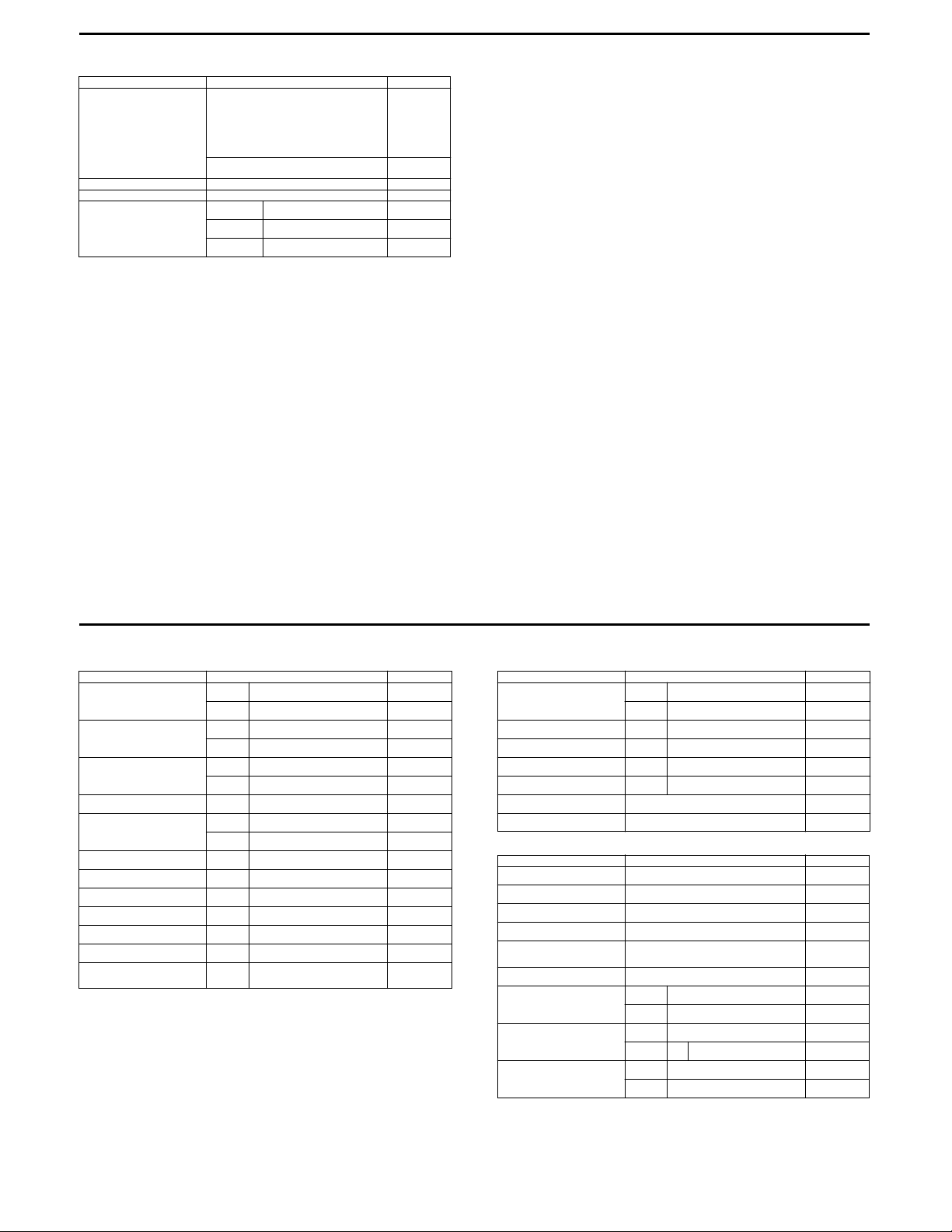
12
FUEL + OIL
Fuel type Use only unleaded gasoline of at least 87 pump
Fuel tank capacity 22 L (5.8/4.8 US/lmp gal)
Engine oil type SAE 10W-40, API SF or SG
Engine oil capac ity
ITEM STD/SPEC. NOTE
octane (R/2 + M/2) or 91 octane or higher rated by
the research method.
Gasoline containing MTBE (Methyl Tertiary Butyl
Ether), less than 10% ethanol, or less than 5%
methanol with appropriate cosolvents and corrosion inhibitor is permissible.
Gasoline used should be graded 91 octane or
higher. An unleaded gasoline is recommended.
Change
Filter change
Overhaul
2 300 ml
(2.4/2.0 US/lmp qt)
2 700 ml
(2.9/2.4 US/lmp qt)
3 100 ml
(3.3/2.7 US/lmp qt)
E-03, 28, 33
Others
9/9
DL650 E-02 , 03, 19 , 24, 28, 33
DL650UE E-19
DL1000
VALVE + GUIDE Unit: mm (in)
Valve diam.
Tappet clearance (when cold)
Valve gui de to val ve stem clea rance
Valve guide I.D.
Valve stem O.D.
Valve stem deflection
Valve stem runout
Valve head thickness
Valve seat width
Valve head radial runout
Valve spring free length
Valve spring tension
ITEM STANDARD LIMIT
IN.
EX.
IN.
EX.
IN.
EX.
IN. & EX.
IN.
EX.
IN. & EX. —
IN. & EX. —
IN. & EX. —
IN. & EX.
IN. & EX. —
IN. & EX. —
IN. & EX.
(20.1 – 23.1 kgf, 44.3 – 51.0 lbs)
36
(1.42)
33
(1.30)
0.10 – 0.20
(0.004 – 0.008)
0.20 – 0.30
(0.008 – 0.012)
0.010 – 0.037
(0.0004 – 0.0015)
0.030 – 0.057
(0.0012 – 0.0022)
5.500 – 5.512
(0.2165 – 0.2170)
5.475 – 5.490
(0.2156 – 0.2161)
5.455 – 5.470
(0.2148 – 0.2154)
0.9 – 1.1
(0.035 – 0.043)
197 – 227 N
at length 35.6 mm (1.40 in)
—
—
—
—
—
—
—
—
—
0.35
(0.014)
0.05
(0.002)
0.5
(0.02)
—
0.03
(0.001)
39.6
(1.56)
—
CAMSHAFT + C YLINDER HEAD Unit: mm (in)
Cam height
Camshaft journal oil clearance
Camsh aft jo urnal holder I.D.
Camsh aft jo urnal O.D.
Camshaft runout
Cam drive idle gear/sprocket thrust
clear ance
Cylinder head distortion
CYLIN DER + PI STON + PISTO N RING Unit: mm (in)
Compr ession pres sure
(Automatic de-comp. actuated)
Compr ession pres sure diffe rence
Piston to cylinder clearance 0.015 – 0.025
Cylinder bore 98.000 – 98.015
Piston diam. 97.980 – 97.995
Cylinder distortion
Piston ring free end gap
Piston ring end ga p
Piston ring to gr oove cle arance
ITEM STANDARD LIMIT
IN.
EX.
IN. & EX.
IN. & EX.
IN. & EX.
IN. & EX. —
ITEM STANDARD LIMIT
(10 – 14 kgf/cm², 142 – 199 psi)
Measure at 10 mm (0.4 in) from the skirt end.
1st Approx. 8.8 (0.35)
2nd Approx. 10.1 (0.40)
1st
2nd RN
1st —
2nd —
36.28 – 36.32
(1.428 – 1.430)
35.68 – 35.72
(1.405 – 1.406)
0.019 – 0.053
(0.0007 – 0.0021)
22.012 – 22.025
(0.8666 – 0.8671)
21.972 – 21.993
(0.8650 – 0.8659)
0.15 – 0.29
(0.006 – 0.011)
—
1 000 – 1 400 kPa
—
(0.0006 – 0.0010)
(3.8583 – 3.8589)
(3.8575 – 3.8581)
—
0.15 – 0.35
(0.006 – 0.014)
0.30 – 0.45
(0.012 – 0.018)
35.98
(1.417)
35.38
(1.393)
0.150
(0.0059)
—
—
0.10
(0.004)
—
0.05
(0.002)
800 kPa
(8 kgf/cm², 114 psi)
200 kPa
(2 kgf/cm², 28 psi)
0.12
(0.0047)
Nicks or
Scratches
97.880
(3.8535)
0.05
(0.002)
7.0
(0.28)
8.1
(0.32)
0.5
(0.02)
0.7
(0.03)
0.18
(0.0071)
0.15
(0.0059)
1/10 E-02, 03, 19, 24, 28, 33
2/10 E-02, 03, 19, 24, 28, 33
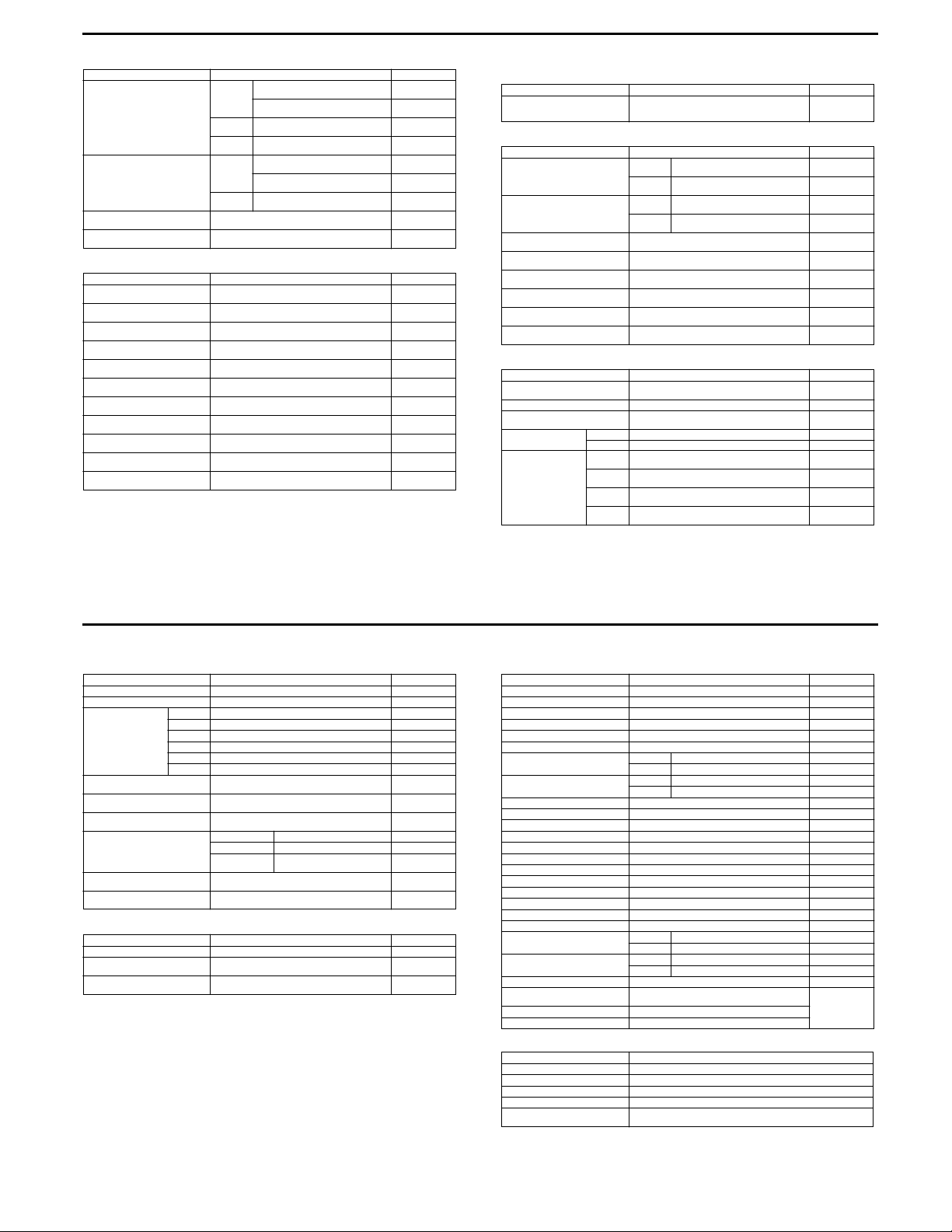
13
Piston ring groove width
Piston ring thick ness
Piston pin bore I.D. 22.002 – 22.008
Piston pinO.D. 21.992 – 22.000
ITEM STANDARD LIMIT
1st
2nd
Oil
1st
2nd
0.93 – 0.95
(0.0366 – 0.0374)
1.55 – 1.57
(0.0610 – 0.0618)
1.01 – 1.03
(0.0398 – 0.0406)
2.51 – 2.53
(0.0988 – 0.0996)
0.86 – 0.91
(0.034 – 0.036)
1.38 – 1.40
(0.054 – 0.055)
0.97 – 0.99
(0.038 – 0.039)
(0.8662 – 0.8665)
(0.8658 – 0.8661)
—
—
—
—
—
—
—
22.0 30
(0.8673)
21.9 80
(0.8654)
CONROD + CRANKSHAFT Unit: mm (in)
Conrod small end I.D. 22.010 – 22.018
Conrod big end side clearance 0.17 – 0.32
Conrod big end width 21.95 – 22.00
Crank pin width 44.17 – 44.22
Conrod big end oil clearance 0.040 – 0.064
Crank pin O.D. 44.976 – 45.000
Crankshaft journal oil clearance 0.002 – 0.029
Crankshaft journal O.D. 47.985 – 48.000
Crankshaft journa
Crankshaft journa
Crankshaft runout
ITEM STANDARD LIMIT
(0.8665 – 0.8668)
(0.007 – 0.013)
(0.864 – 0.866)
(1.739 – 1.741)
(0.0016 – 0.0025)
(1.7707 – 1.7717)
(0.0008 – 0.0011)
l holder width 25.2 – 25.4
l width 25.50 – 25.55
(1.8892 – 1.8898)
(0.99 – 1.00)
(1.004 – 1.006)
—
22.0 40
(0.8677)
0.50
(0.020)
—
—
0.080
(0.0031)
—
0.080
(0.0031)
—
—
—
0.05
(0.004)
OIL PUMP
Oil pressure (at 60 °C, 140 °F) Above 400 kPa
ITEM STANDARD LIMIT
Below 700 kPa (7.0 kgf/cm², 100
CLUTCH
Drive plate thickness
Drive plate claw width
Driven plate distortion
Clutch spring free length 61.5 – 62.5
Clutch master cylinder bore 14.000 – 14.043
Clutch master cylinder piston diam. 13.957 – 13.984
Clutch release cylinder bore 35.700 – 35.762
Clutch release cylinder piston
diam.
ITEM STANDARD LIMIT
No. 1 and 3
No. 2
No. 1 and 3
No. 2
(4.0 kgf/cm², 57 psi)
at 3 000 r/min
2.92 – 3.08
(0.115 – 0.121)
3.72 – 3.88
(0.146 – 0.153)
13.85 – 13.96
(0.545 – 0.550)
13.90 – 14.00
(0.547 – 0.551)
—
(2.42 – 2.46)
(0.5512 – 0.5528)
(0.5495 – 0.5505)
(1.4055 – 1.4079)
35.650 – 35.675
(1.4035 – 1.4045)
psi)
Unit: mm (in)
THERMOSTAT + RADIATOR + FAN
Thermostat valve opening temperature
Thermostat valve lift Over 8 mm (0.31 in) at 100 °C (212 °F) —
Radiator cap valve opening pres-
sure
Cooling fan ther-
moswitch operating
Engine coolant temperatu re sens or resi stance
ITEM STANDARD LIMIT
ON→OFF Approx. 105 °C (221 °F) —
ON→OFF Approx. 100 °C (212 °F) —
20 °C
(68 °F)
40 °C
(104 °F)
60 °C
(140 °F)
80 °C
(176 °F)
86.5 – 89.5 °C
(188 – 1 93 °F)
110 kPa
(1.1 kgf/cm², 15.6 psi)
Approx. 2.45 kΩ —
Approx. 1.148 kΩ —
Approx. 0.587 kΩ —
Approx. 0.322 kΩ —
—
2.62
(0.103)
3.42
(0.135)
13.05
(0.514)
13.10
(0.516)
0.10
(0.004)
59.4
(2.34)
—
—
—
—
—
—
3/10 E-02, 03, 19, 24, 28, 33
DRIVE TRAIN Unit: mm (in) Expect ratio
Primary reduction ratio 1.838 (57/31) —
Final reduction r atio
Gear ratio
Shift fork to groove clearance
Shift fork groove width
Shift fork thickness
Drive chain
Drive chain slack
Gearshift lever height 25
ITEM STANDARD LIMIT
Low 3.000 (36/ 12) —
2nd 1.933 (29/15) —
3rd 1.500 (27/18) —
4th 1.227 (27/22) —
5th 1.086 (25/23) —
Top 0.913 (2 1/23) —
20-pitch length —
2.411 (41/17) —
0.1 – 0.3
(0.004 – 0.012)
5.0 – 5.1
(0.197 – 0.201)
4.8 – 4.9
(0.189 – 0.193)
Type RK525SMOZ7 —
Links 112 links, ENDLESS —
20 – 30
(0.8 – 1.2)
(1.0)
(0.020)
319.4
(12.6)
0.50
—
—
—
—
INJECTOR + FUEL PUMP + FUEL PRESSURE REGURATOR
Injec tor re sistan ce 12 – 18 Ω at 20 °C (68 °F)
Fuel pump discharge amount Approx. 1.2 L (1.3/1.1 US/lmp qt)
Fuel pressure regulator operating
set pressure
ITEM SPECIFICATION NOTE
for 1 minute at 300 kPa (3.0 kgf/cm², 43 psi)
Approx. 300 kPa (3.0 kgf/cm², 43 psi)
4/10 E-02, 03, 19, 24, 28, 33
FI-SENSORS
CMP sensor output voltage More than 3.7 V
CKP sensor resistance 130 – 240 Ω
CKP sensor peak voltage More than 3.7 V (When cranking)
IAP sen sor input voltage 4. 5 – 5.5 V
IAP sensor output voltage Approx. 2.5 V at idle speed
TP sens or input vol tage 4. 5 – 5.5 V
TP sensor resistance Closed Approx. 1.1 kΩ
TP sensor output voltage Closed Approx. 1.1 V
ECT se nsor in put voltage 4.5 – 5.5 V
ECT se nsor re isitance Appr ox. 2.4 5 kΩ at 20 °C (68 °F)
IAT sensor input volatage 4.5 – 5.5 V
IAT sensor resis tance Approx 2.45 kΩ at 20 °C (68 °F)
AP sens or input vol tage 4.5 – 5.5 V
AP sensor output voltage Approx. 4.0 V at 760 mmHg (100 kPa)
TO sensor resistance 19.1 – 19.7 kΩ
TO sensor voltage Approx. 0.4 – 1.4 V
GP switch voltage More than 1.0 V (From 1st to top)
Injector voltage Battery voltage
Ignition coil primary peak voltage More than 150 V (When cranking)
STP sen sor input voltage 4.5 – 5 .5 V
STP sensor resistance Closed Approx. 1.1 kΩ
STP sensor output voltage Closed Approx. 1.1 V
STV actuator resistance 4.8 – 7.2 Ω
Heated oxygen sensor output volt-
age
PAIR solenoid valve resistance 20 – 24 Ω at 20 °C (68 °F)
THROTTLE BODY
ID No. 06G3 (For E-02, 19), 06G4 (For E-33), 06G5 (For E-03, 24, 28)
Bore size 45 mm
Fast idle r/min 1 500 – 2 100 r/min at 25 °C (77 °F)
Idle r/min 1 200 ± 100 r/min/Warmed engine
Throt tle ca ble play 2.0 – 4.0 r/m in
ITEM SPECIFICATION NOTE
Opened Approx. 4.3 kΩ
Opened Approx. 4.3 V
Opened Approx. 4.3 kΩ
Opened Approx. 4.3 V
Less t han 0.4 V at idle sp eed
(After warming up)
ITEM SPECIFICATION
(0.08 – 0.16 in)
European
marketsHeated oxygen sensor resistance 4 – 5 Ω at 23 °C (73.4 °F)
5/10 E-02, 03, 19, 24, 28, 33
6/10 E-02, 03, 19, 24, 28, 33
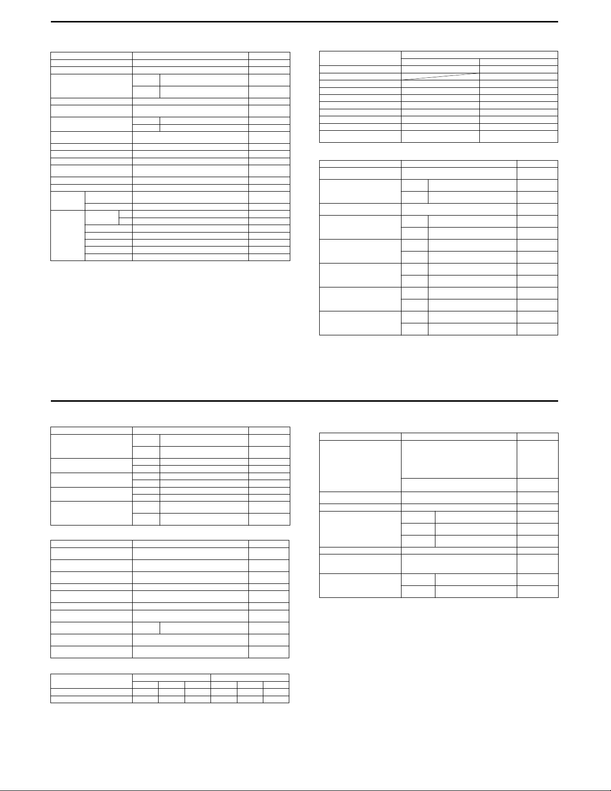
14
ELECTRICAL Unit: mm (in)
Ignition timing 4° B.T.D.C. at 1 200 r/min
Firing order 1·2
Spark plug
Spark performance Over 8 (0.3) at 1 atm.
Crankshaft position sensor resis-
tance
Ignition coil resistance Primary 2 – 5 Ω
Crankshaft position sensor peak
voltage
Ignition coil primary peak voltage More than 150 V When cranking
Generator coil resistance 0.2 – 0.5 Ω Y – Y
Generator Max. output Approx. 400 W at 5 000 r/min
Gener ator no -load voltage
(When engine is cold)
Regulated voltage 14.0 – 15.5 V at 5 000 r/min
Start er relay re sistance 3 – 6 Ω
Battery Type
Fuse size
ITEM SPECIFICATION NOTE
Type
Gap
Secondary 24 – 37 kΩ tap – Plug cap
More than 75 V (AC) at 5 000 r/min
designation
Capacity 12 V 43.2 kC (12 Ah)/10 HR
Headlight
HI 15 A
LO 15 A
Turn signal 15 A
Ignition 10 A
Fan motor 15 A
Meter 10 A
Main 30 A
NGK: CR8EK
Denso: U24ETR
0.6 – 0.7
(0.024 – 0.028)
130 – 240 Ω Bl – G
More than 3.7 V When cranking
FTX14-BS
tap – tap
WATTAGE Unit: W
ITEM
Headlight
Position/Parking light
Brake light/Taillight
Turn signal light 12 V 2 1 W ←
License light
Speedometer light LED ←
Turn signal indicator light
High beam indicator light
Neutral indicator light
Oil pressure/Coolant temp./Fuel
injection warning
BRAKE + WHEEL Unit: mm (in)
Rear brake pedal height 20 – 30
Brake disc thickness
Brake disc runout
(Front & Rear)
Master cylinder bore
Master cylinder piston diam.
Brake caliper cylinder bore
Brake caliper piston diam.
Wheel rim runout
(Front & Rear)
ITEM STANDARD LIMIT
E-03, 24, 28, 33 Others
12 V 60/55 W × 2 (H4) ←
12 V 21/5 W × 2 ←
Front
Rear
Front
Rear
Front
Rear
Front
Rear
Front
Rear
Axial —
Radial —
SPECIFICATION
12 V 5 W × 2
12 V 5 W ←
LED ←
LED ←
LED ←
LED ←
(0.8 – 1.2)
5.0 ± 0. 2
(0.197 ± 0.008)
5.0 ± 0. 2
(0.197 ± 0.008)
—
15.870 – 15.913
(0.6248 – 0.6265)
14.000 – 14.043
(0.5512 – 0.5529)
15.827 – 15.854
(0.6231 – 0.6242)
13.957 – 13.984
(0.5495 – 0.5506)
30.230 – 30.306
(1.1902 – 1.1931)
38.180 – 38.230
(1.5031 – 1.5051)
30.150 – 30.200
(1.1870 – 1.1890)
38.098 – 38.148
(1.4999 – 1.5019)
—
4.5
(0.18)
4.5
(0.18)
0.30
(0.012)
—
—
—
—
—
—
—
—
2.0
(0.08)
2.0
(0.08)
7/10 E-02, 03, 19, 24, 28, 33
Wheel axle runout
Wheel rim size Front 19M/C × MT 2.50 —
Tire si ze Fron t 1 10/80R 19M/C 59H —
Tire type Front BRIDGESTONE: TW101 F —
Tire tread depth
SUSPENSION Unit: mm (in)
Front fork stroke 160
Front fork spring free length 433.6
Front fork oil l evel (without s pring,
inner tube fully compressed)
Front fork oil type SUZUKI FORK OIL SS-08 or an equivalent fork oil
Front fork oil capacity (each leg) 496.0 ml
Front fork spring adjuster 3rd groove from top —
Rear shock absorber spring
adjus ter
Rear shock absorber damping
force adjuster
Rear wheel travel
Swingarm pivot shaft runput
TIRE PRESSURE
ITEM STANDARD LIMIT
ITEM STANDARD LIMIT
COLD INFLATION
TIRE PRESSURE
FRONT 250 2.50 36 250 2.50 36
REAR 250 2.50 36 280 2.80 41
Front —
Rear —
Rear 17M/C × MT 4.00 —
Rear 150/70R17M/C 69H —
Rear BRIDGESTONE: TW152 F —
Front —
Rear —
(6.3)
(17.07)
140.0
(5.51)
(16.76/17.46 US/lmp oz)
2nd groove from bottom —
Rebound 7/8 turn out from stiffest position —
SOLO RIDING DUAL RIDI NG
kPa
159
(6.3)
—
kgf/cm² psi
kPa
kgf/cm² psi
0.25
(0.010)
0.25
(0.010)
1.6
(0.06)
2.0
(0.08)
—
424
(16.7)
—
—
0.3
(0.01)
8/10 E-02, 03, 19, 24, 28, 33
FUEL + OIL + ENGINE COOLANT
Fuel type Use only unleaded gasoline of at least 87 pump
Fuel ta nk 17 L
Engine oil type SAE 10W-40, API SF or SG
Engine oil capac ity
Brake fluid type DOT 4
Engine coolant type Use an anti-freeze/coolant compatible with alumi-
Engien coolant Reserve
ITEM SPECIFICATION NOTE
octane (R/2 + M/2) or 91 octane or higher rated by
the research method. Gasoline containing MTBE
(Methyl Tertiary Butyl Ether), less than 10% ethanol, or less than 5% methanol with appropriate
cosolvents and corrosion inhibitor is permissible.
Gasoline used should be graded 91 octane or
higher. An unleaded gasoline is recommended.
(4.5/3.7 US/lmp gal)
Change
Filter change
Overhaul
num radiator, mixed with distilled water only, at the
ratio o f 50:50.
tank side
Engine side
2 700 ml
(2.9/2.4 US/lmp qt)
2 900 ml
(3.1/2.6 US/lmp qt)
3 300 ml
(3.5/2.9 US/lmp qt)
Approx. 250 ml
(0.3/0.2 US/lmp qt)
Approx. 1 950 ml
(2.1/1.7 US/lmp qt)
E-03, 28, 33
The others
9/10 E-02, 03, 19, 24, 28, 33
10/10 E-02, 03, 19, 24, 28, 33
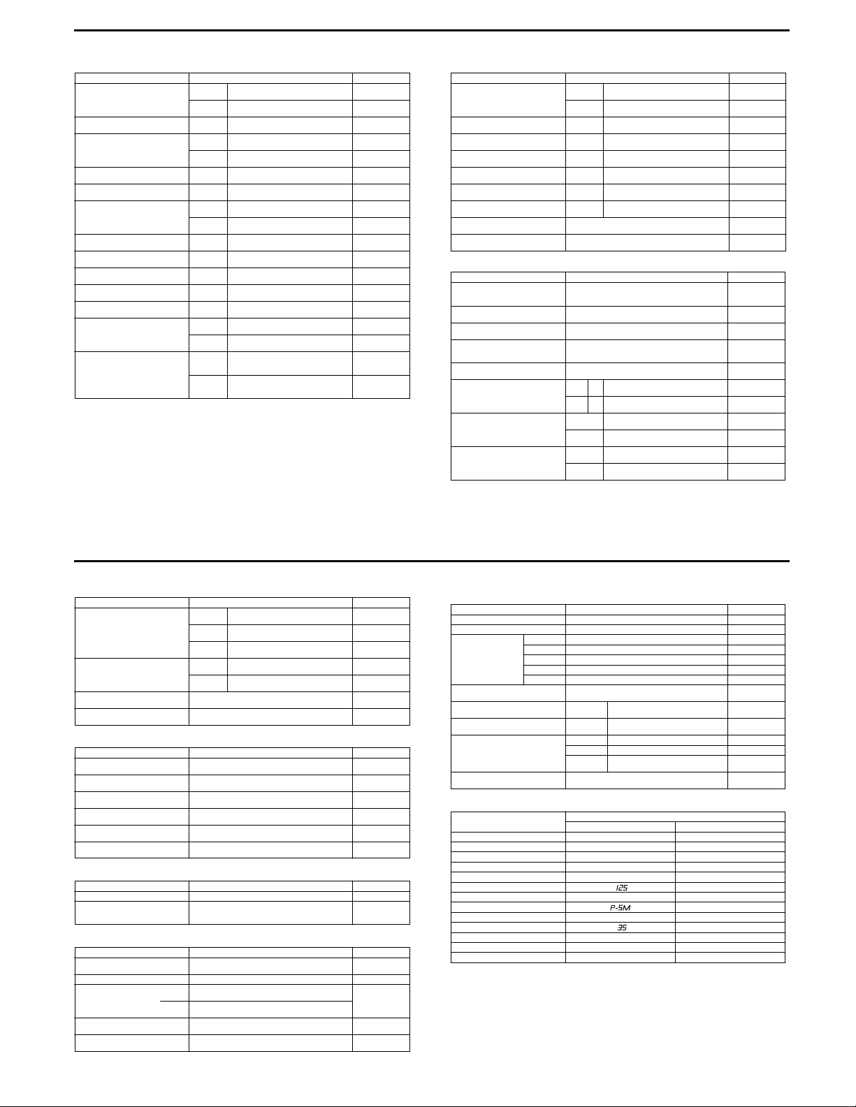
DR200SE (E-03, 28, 33)
VALVE + GUIDE Unit: mm (in)
Valve diam.
Valve clearance (when cold)
Valve gui de to val ve stem
clear ance
Valve stem deflection
Valve guide I.D.
Valve stem O.D.
Valve stem runout
Valve head thickness
Valve stem end length
Valve seat width
Valve head radial runout
Valve spring free length
(IN. & EX.)
Valve spring tension
(IN. & EX.) INNER
ITEM STANDARD LIMIT
IN.
EX.
IN. & EX.
IN.
EX.
IN. & EX. —
IN. & EX.
IN.
EX.
IN. & EX. —
IN. & EX. —
IN. & EX. —
IN. & EX.
IN. & EX. —
INNER —
OUTER —
(7.1 – 9.2 kgf, 15.7 – 20.3 lbs)
OUTER
(17.3 – 21.3 kgf, 38.1 – 47.0 lbs)
33
(1.3)
28
(1.1)
0.08 – 0.13
(0.003 – 0.005)
0.010 – 0.037
(0.0004 – 0.0015)
0.030 – 0.057
(0.0012 – 0.0022)
5.500 – 5.512
(0.2165 – 0.2170)
5.475 – 5.490
(0.2146 – 0.2161)
5.455 – 5.470
(0.2148 – 0.2154)
0.9 – 1.1
(0.04 – 0.05)
70 – 90 N
at len gth 32. 5 mm ( 1.28 in )
170 – 209 N
at len gth 36. 0 mm ( 1.42 in )
—
—
—
—
—
0.35
(0.014)
—
—
—
0.05
(0.002)
0.5
(0.02)
2.6
(0.1)
—
0.03
(0.001)
35.1
(1.38)
40.6
(1.60)
—
—
CAMSHAFT + C YLINDER HEAD Unit: mm (in)
Cam height
Camshaft journal oil clearance
Camsh aft jo urnal holder I.D.
Camsh aft jo urnal O.D.
Camshaft runout
Rocker arm I.D.
Rocker ar m shaft O.D.
Cylinder head distortion
Cylinder head cover distortion
CYLIN DER + PI STON + PISTO N RING Unit: mm (in)
Compr ession pres sure
Piston to cylinder clearance 0.040 – 0.050
Cylinder bore 66.000 – 66.015
Piston diam. 65.955 – 65.970
Cylinder distortion
Piston ring free end gap
Piston ring end ga p
Piston ring to gr oove cle arance
ITEM STANDARD LIMIT
IN.
EX.
IN. & EX.
IN. & EX.
IN. & EX.
IN. & EX. —
IN. & EX.
IN. & EX.
ITEM STANDARD LIMIT
Measure at 15 mm (0.59 in) from the skirt end.
1st R Approx. 7.5 (0.30)
2nd R Approx. 9.4 (0.37)
1st
2nd
1st —
2nd —
34.174 – 34.218
(1.3454 – 1.3472)
33.804 – 33.848
(1.3309 – 1.3326)
0.032 – 0.066
(0.0013 – 0.0026)
22.012 – 22.025
(0.8666 – 0.8671)
21.959 – 21.980
(0.8645 – 0.8654)
12.000 – 12.018
(0.4724 – 0.4731)
11.977 – 11.995
(0.4715 – 0.4722)
—
—
1 400 kPa
2
, 199 psi)
(14 kgf/cm
(0.0016 – 0.0020)
(2.5984 – 2.5990)
(2.5966 – 2.5972)
—
0.10 – 0.25
(0.004 – 0.010)
0.10 – 0.25
(0.004 – 0.010)
33.870
(1.3335)
33.500
(1.3189)
0.150
(0.0059)
—
—
0.10
(0.004)
—
—
0.05
(0.002)
0.05
(0.002)
980 kPa
(9.8 kgf /cm
139 psi)
0.120
(0.0047)
66.090
(2.6020)
65.880
(2.5937)
0.05
(0.002)
6.0
(0.24)
7.5
(0.30)
0.5
(0.02)
0.5
(0.02)
0.18
(0.007)
0.15
(0.006)
2
15
,
1/7 E-03, 28, 33
Piston ring groove width
Piston ring thick ness
Piston pin bore 16.002 – 16.008
Piston pin O.D. 15.996 – 16.000
ITEM STANDARD LIMIT
1st
2nd
Oil
1st
2nd
1.01 – 1.03
(0.040 – 0.041)
1.21 – 1.23
(0.047 – 0.048)
2.01 – 2.03
(0.079 – 0.080)
0.970 – 0.990
(0.038 – 0.039)
1.170 – 1.190
(0.046 – 0.047)
(0.6300 – 0.6302)
(0.6298 – 0.6299)
—
—
16.030
(0.6311)
15.980
(0.6291)
CONROD + CRANKSHAFT Unit: mm (in)
Conrod small end I.D. 16.006 – 16.014
Conrod deflection
Conrod big end side clearance 0.10 – 0.45
Conrod big end width 17.95 – 18.00
Crank web to web width 53.0 ± 0.1
Crankshaft runout
ITEM STANDARD LIMIT
(0.6302 – 0.6305)
—
(0.004 – 0.018)
(0.707 – 0.709)
(2.09 ± 0.004)
—
16.040
(0.6315)
3.0
(0.12)
1.00
(0.039)
—
—
0.08
(0.003)
OIL PUMP
Oil pump reduction ratio 2.000 (30/15) —
Oil pressure (at 60 °C, 140 °F) Above 15 kPa (0.15 kgf/cm
CLUTCH
Clutch lever play 10 – 15
Clutch release screw 1/4
Clutch plate thickness
Driven plate distortion
Clutch spring free length
ITEM STANDARD LIMIT
2
, 2.1 psi)
2
Below 35 kPa (0.35 kgf/cm
at 3 000 r/min
ITEM STANDARD LIMIT
(0.4 – 0 .6)
1 pc.
5 pcs.
2.9 – 3 .1
(0.114 – 0.122)
2.95 – 3.15
(0.116 – 0.124)
, 4.9 ps i)
A
turn back —
—
—
—
Unit: mm (in)
—
2.6
(0.10)
0.10
(0.004)
31.0
(1.22)
2/7 E-03, 28, 33
TRANSMISSTION + DRIVE CHAIN Unit: mm (in) Except ratio
Primary reduction ratio 3.157 (60/19) —
Final reduction ratio 3.000 (45/15) —
Gear ratios Low 3.000 (33/11) —
Shift fork to groove clearance 0.10 – 0.30
Shift fork gro ove widt h
Shift fork thickness
Drive chain Type D.I.D. 520VC5 —
Drive c hain slack 2 5 – 40
CARBURETOR
Carburetor type MIKUNI BST31SS ←
Bore size 31 mm ←
I.D. No. 42AC 42AE
Idle r/min 1 500 ± 100 r/min ←
Float height 13.0 ± 1.0 mm (0.51 ± 0.04 in) ←
Main jet (M.J. ) # ←
Jet needle (J.N.) 5D77 ←
Needle jet (N.J.) ←
Throttle valve (Th.V.) #125 ←
Pilot jet (P.J.) # ←
Starter jet (G .S.) #25 ←
Pilot screw (P.S.) PRE-SET ←
Throt tle ca ble play 2 – 4 mm ( 0.08 – 0.16 in) ←
ITEM STANDARD LIMIT
2nd 1.933 (29/15) —
3rd 1.437 (23/16) —
4th 1.095 (23/21) —
Top 0.913 (21/23) —
(0.004 – 0.012)
5.0 – 5 .1
(0.20 – 0.21)
4.8 – 4 .9
(0.18 – 0.19)
(1.0 – 1.6)
SPECIFICATION
—
ITEM
No.1, 2, 3
No.1, 2, 3
Links 112 links —
20-pit ch
length
E-03, 28 E-33
—
—
—
319.4
(12.57)
—
3/7 E-03, 28, 33
4/7 E-03, 28, 33
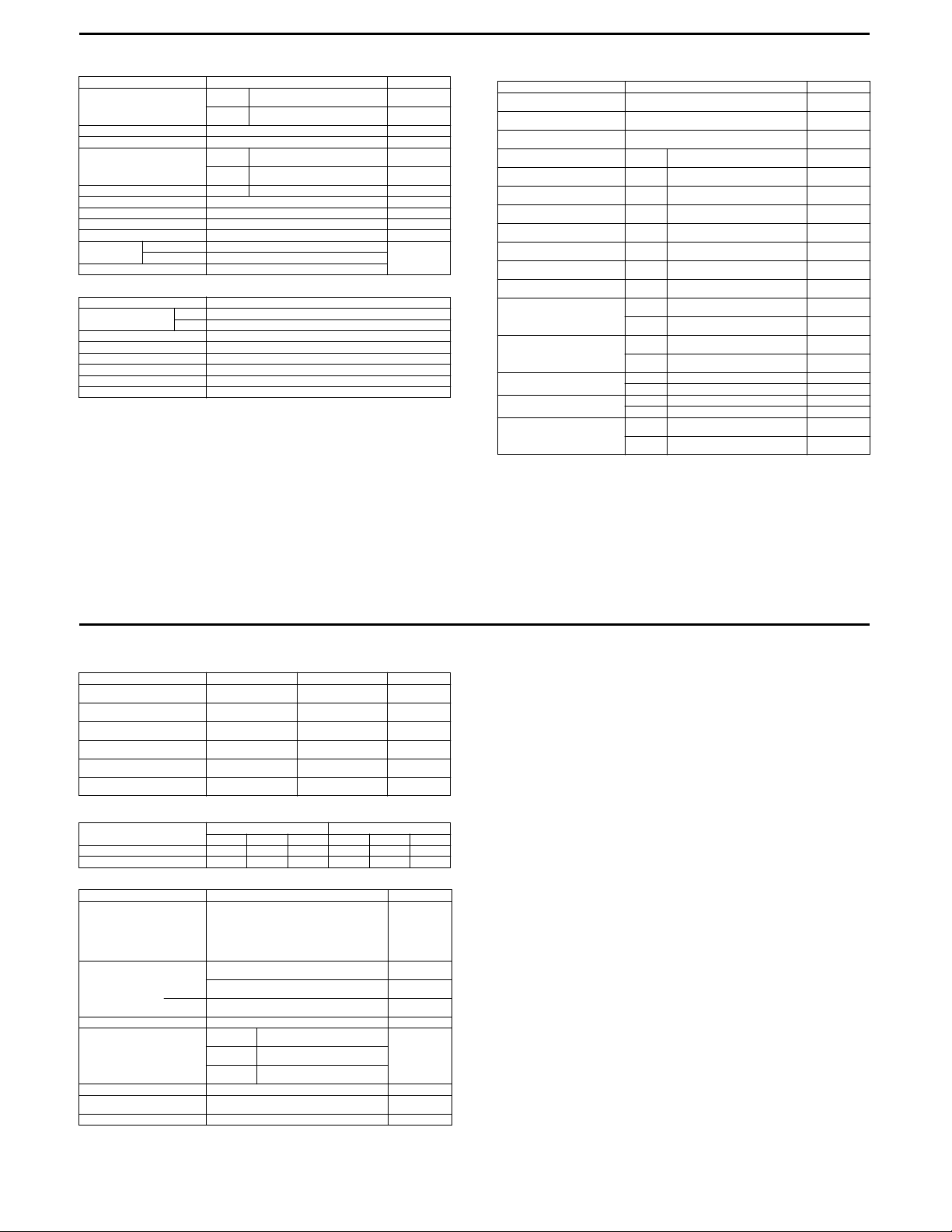
16
ELECTRICAL Unit: mm (in)
Spark plug
Spark performance Over 8 mm (0.3) at 1 atm.
Signal coil resitance 100 – 140 Ω G – Bl
Ignition coil resistance
Generator coil resistance Charging 0.1 – 1.5 Ω
Generator no-load voltage More than 60 V (AC) at 5 000 r/min
Generator Max. output 150 W at 5 000 r/min
Regulated voltage 13.0 – 16.0 V at 5 000 r/min
Starter relay resistance 2 – 6 Ω
Battery Type designation YTX7L-BS
Fuse size 20 A
WATTAGE Unit: W
Headlight
Brake light/Taillight 21/5
Turn signal light 21
Speedometer light 3.4
Turn signal indicator light 3.4
High beam indicator light 1.7
Neutral indicator light 3.4
ITEM SPECIFICATION N OTE
Capacity 12 V 21.6 kC (6 Ah)/10 HR
ITEM SPECIFICATION
Type
Gap
Primary 2 – 6 Ω
Secondary 20 – 30 kΩ
HI
LO
DENSO: X24ESR-U
NGK: CR8EA
0.6 – 0.7
(0.024 – 0.028)
60
55
Terminal –
Terminal
Plug cap –
Terminal
BRAKE + WHEEL Unit: mm (in)
Brake leve r play 0.1 – 0. 3
Rear brake pedal free travel 20 – 30
Rear brake pedal height 2.5
Brake drum I.D.
Brake lining thickness
Brake disc thickness
Brake disc runout
Master cylinder bore
Master cylinder piston diam.
Brake caliper cylinder bore
Brake caliper piston diam.
Wheel rim runout
Wheel axle runout
Wheel rim size Front J21 × 1.60 —
Tire size Front 70/100-21 M/C 44P —
Tire tread depth
ITEM STANDARD LIMIT
(0.004 – 0.010)
(0.8 – 1 .2)
Rear —
Rear —
Front
Front —
Front
Front
Front
Front
Axial —
Radial —
Front —
Rear —
Rear J18 × 2.15 —
Rear 100/90-18 M/C 56P —
Front —
Rear —
(0.10)
3.5 ± 0.2
(0.138 ± 0.008)
12.700 – 12.743
(0.5000 – 0.5017)
12.657 – 12.684
(0.4983 – 0.4994)
33.960 – 34.010
(1.3370 – 1.3390)
33.878 – 33.928
(1.3338 – 1.3357)
—
—
—
130.7
(5.15)
1.5
(0.06)
3.0
(0.12)
0.30
(0.012)
—
—
—
—
2.0
(0.08)
2.0
(0.08)
0.25
(0.010)
0.25
(0.010)
3.0
(0.12)
3.0
(0.12)
5/7 E-03, 28, 33
SUSPENSION Unit: mm (in)
Front fork stroke 205
Front fork spring free length
Front fork oil level 179.5
Rear shock absorber spring
pre-set length
Rear wheel travel 205
Swingarm pivot shaft runout
ITEM STANDAR D LI MIT N OTE
(8.1)
—
(7.07)
231
(9.1)
(8.1)
—
—
561
(22.1)
—
—
—
0.6
(0.02)
TIRE PRESSUER
COLD INFLATION
TIRE PRESSURE
FRONT 150 1.50 22 150 1.50 22
REAR 175 1.75 25 200 2.00 29
SOLO RIDING DUAL RIDI NG
2
kPa kgf/cm
psi kPa k gf/cm2psi
FUEL + OIL
Fuel type Use only unleaded gasoline of at least 87 pump
Fuel tank capacity including
Engine oil type SAE 10 W-40, API SF or SG
Engine oil capac ity
Front fork oil type Fork oil #10
Front fork oil capacity (each leg) 309 ml
Brake fluid type DOT 4
ITEM SPECIFICATION NOTE
octane (R/2 + M/2) or 91 octane or higher rated by
the research method. Gasoline containing MTBE
(Methyl Tertiary Butyl Ether), less than 10% ethanol, or less than 5% methanol with appropriate
cosolvents and corrosion inhibitor is permissible.
reserve
reserve
Change
Filter change
Overhaul
13.0 L
(3. 4/2.9 U S/lmp qt)
12.5 L
(3. 3/2.7 U S/lmp qt)
2.5 L
(0. 7/0.5 U S/lmp qt)
850 ml
(0.90/0.75 US/lmp qt)
950 ml
(1.00/0.84 US/lmp qt)
1 100 ml
(1. 2/1.0 U S/lmp qt)
(10.4/10.9 US/lmp oz)
E-03, 28
E-33
6/7 E-03, 28, 33
7/7 E-03, 28, 33
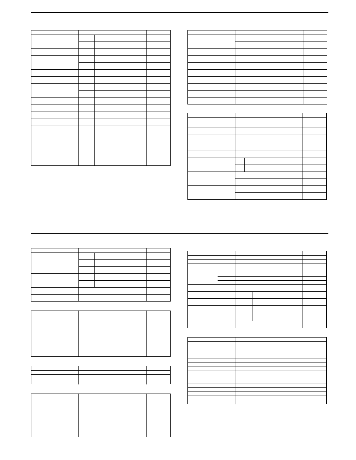
DR200SE (E-06, 24)
VALVE + GUIDE Unit: mm (in)
Valve diam.
Valve clearance (when cold)
Valve gui de to val ve stem
clear ance
Valve stem deflection
Valve guide I.D.
Valve stem O.D.
Valve stem runout
Valve head thickness
Valve stem end length
Valve seat width
Valve head radial runout
Valve spring free length
(IN. & EX.)
Valve spring tension
(IN. & EX.) INNER
ITEM STANDARD LIMIT
IN.
EX.
IN. & EX.
IN.
EX.
IN. & EX. —
IN. & EX.
IN.
EX.
IN. & EX. —
IN. & EX. —
IN. & EX. —
IN. & EX.
IN. & EX. —
INNER —
OUTER —
(7.1 – 9.2 kgf, 15.7 – 20.3 lbs)
OUTER
(17.3 – 21.3 kgf, 38.1 – 47.0 lbs)
33
(1.3)
28
(1.1)
0.08 – 0.13
(0.003 – 0.005)
0.010 – 0.037
(0.0004 – 0.0015)
0.030 – 0.057
(0.0012 – 0.0022)
5.500 – 5.512
(0.2165 – 0.2170)
5.475 – 5.490
(0.2146 – 0.2161)
5.455 – 5.470
(0.2148 – 0.2154)
0.9 – 1.1
(0.04 – 0.05)
70 – 90 N
at len gth 32. 5 mm ( 1.28 in )
170 – 209 N
at len gth 36. 0 mm ( 1.42 in )
—
—
—
—
—
0.35
(0.014)
—
—
—
0.05
(0.002)
0.5
(0.02)
2.6
(0.1)
—
0.03
(0.001)
35.1
(1.38)
40.6
(1.60)
—
—
CAMSHAFT + C YLINDER HEAD Unit: mm (in)
Cam height
Camshaft journal oil clearance
Camsh aft jo urnal holder I.D.
Camsh aft jo urnal O.D.
Camshaft runout
Rocker arm I.D.
Rocker ar m shaft O.D.
Cylinder head distortion
Cylinder head cover distortion
CYLIN DER + PI STON + PISTO N RING Unit: mm (in)
Compr ession pres sure
Piston to cylinder clearance 0.040 – 0.050
Cylinder bore 66.000 – 66.015
Piston diam. 65.955 – 65.970
Cylinder distortion
Piston ring free end gap
Piston ring end ga p
Piston ring to gr oove cle arance
ITEM STANDARD LIMIT
IN.
EX.
IN. & EX.
IN. & EX.
IN. & EX.
IN. & EX. —
IN. & EX.
IN. & EX.
ITEM STANDARD LIMIT
Measure at 15 mm (0.59 in) from the skirt end.
1st R Approx. 7.5 (0.30)
2nd R Approx. 9.4 (0.37)
1st
2nd
1st —
2nd —
34.174 – 34.218
(1.3454 – 1.3472)
33.804 – 33.848
(1.3309 – 1.3326)
0.032 – 0.066
(0.0013 – 0.0026)
22.012 – 22.025
(0.8666 – 0.8671)
21.959 – 21.980
(0.8645 – 0.8654)
12.000 – 12.018
(0.4724 – 0.4731)
11.977 – 11.995
(0.4715 – 0.4722)
—
—
1 400 kPa
2
, 199 psi)
(14 kgf/cm
(0.0016 – 0.0020)
(2.5984 – 2.5990)
(2.5966 – 2.5972)
—
0.10 – 0.25
(0.004 – 0.010)
0.10 – 0.25
(0.004 – 0.010)
33.870
(1.3335)
33.500
(1.3189)
0.150
(0.0059)
—
—
0.10
(0.004)
—
—
0.05
(0.002)
0.05
(0.002)
980 kPa
(9.8 kgf /cm
139 psi)
0.120
(0.0047)
66.090
(2.6020)
65.880
(2.5937)
0.05
(0.002)
6.0
(0.24)
7.5
(0.30)
0.5
(0.02)
0.5
(0.02)
0.18
(0.007)
0.15
(0.006)
2
17
,
1/7 E-06, 24
Piston ring groove width
Piston ring thick ness
Piston pin bore 16.002 – 16.008
Piston pin O.D. 15.996 – 16.000
ITEM STANDARD LIMIT
1st
2nd
Oil
1st
2nd
1.01 – 1.03
(0.040 – 0.041)
1.21 – 1.23
(0.047 – 0.048)
2.01 – 2.03
(0.079 – 0.080)
0.970 – 0.990
(0.038 – 0.039)
1.170 – 1.190
(0.046 – 0.047)
(0.6300 – 0.6302)
(0.6298 – 0.6299)
—
—
16.030
(0.6311)
15.980
(0.6291)
CONROD + CRANKSHAFT Unit: mm (in)
Conrod small end I.D. 16.006 – 16.014
Conrod deflection
Conrod big end side clearance 0.10 – 0.45
Conrod big end width 17.95 – 18.00
Crank web to web width 53.0 ± 0.1
Crankshaft runout
ITEM STANDARD LIMIT
(0.6302 – 0.6305)
—
(0.004 – 0.018)
(0.707 – 0.709)
(2.09 ± 0.004)
—
16.040
(0.6315)
3.0
(0.12)
1.00
(0.039)
—
—
0.08
(0.003)
OIL PUMP
Oil pump reduction ratio 2.000 (30/15) —
Oil pressure (at 60 °C, 140 °F) Above 15 kPa (0.15 kgf/cm
CLUTCH
Clutch lever play 10 – 15
Clutch release screw 1/4 turn back —
Clutch plate thickness
Driven plate distortion
Clutch spring free length
ITEM STANDARD LIMIT
2
, 2.1 psi)
2
Below 35 kPa (0.35 kgf/cm
at 3 000 r/min
ITEM STANDARD LIMIT
(0.4 – 0 .6)
1 pc.
5 pcs.
2.9 – 3 .1
(0.114 – 0.122)
2.95 – 3.15
(0.116 – 0.124)
, 4.9 ps i)
—
—
—
Unit: mm (in)
—
2.6
(0.10)
0.10
(0.004)
31.0
(1.22)
2/7 E-06, 24
TRANSMISSTION + DRIVE CHAIN Unit: mm (in) Except ratio
Primary reduction ratio 3.157 (60/19) —
Final reduction ratio 3.916 (47/12) —
Gear ratios Low 3.000 (33/11) —
Shift fork to groove clearance 0.10 – 0.30
Shift fork gro ove widt h
Shift fork thickness
Drive chain Type D.I.D. 520VC5 —
Drive c hain slack 2 5 – 40
CARBURETOR
Carbur etor ty pe M IKUNI B ST31SS
Bore size 31 mm
I.D. No. 42AA
Idle r/min 1 500 ± 100 r/min
Float height 13.0 ± 1.0 mm (0.51 ± 0.04 in)
Main jet (M.J. ) #122. 5
Main air jet (M.A.J) 0.8 mm
Jet needle (J.N.) 5D26-3rd
Needle jet (N.J.) P-5
Throttle valve (Th.V.) #125
Pilot jet (P.J.) #40
Valve seat (V.S.) 1.5 mm
Starter jet (G .S.) #25
Pilot screw (P.S.) 1 and 1/2 turns out
Throttle cable play 2 – 4 mm (0.08 – 0.16 in)
ITEM STANDARD LIMIT
2nd 1.933 (29/15) —
3rd 1.437 (23/16) —
4th 1.095 (23/21) —
Top 0.913 (21/23) —
(0.004 – 0.012)
No.1, 2, 3
No.1, 2, 3
Links 112 links, ENDLESS —
20-pit ch
length
ITEM SPECIFICATION
(0.20 – 0.21)
(0.18 – 0.19)
(1.0 – 1.6)
5.0 – 5 .1
4.8 – 4 .9
—
—
—
—
319.4
(12.57)
—
3/7 E-06, 24
4/7 E-06, 24
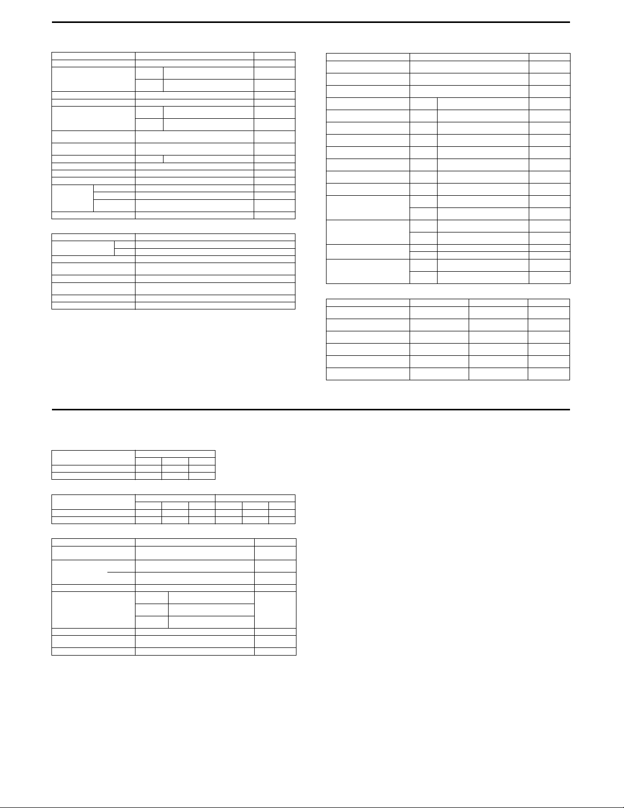
18
ELECTRICAL Unit: mm (in)
Ignition timing 7°B.T.D.C. Below at 1 500 r/min
Spark plug
Spark performance Over 8 mm (0.3) at 1 atm.
Signal coil resitance 100 – 140 Ω G – Bl
Ignition coil resistance
Signal coil peak voltage
Ignition coil primary peak voltage
Generator coil resistance Charging 0.1 – 1.5 Ω —
Generator no-load voltage More than 70 V (AC) at 5 000 r/min
Regulated voltage 13.0 – 16.0 V at 5 000 r/min
Starter relay resistance 2 – 6 Ω
Battery Type designation YTX7L-BS
Fuse size 20 A
WATTAGE Unit: W
Headlight
Brake light/Taillight 21/5
Turn signal light
(For South Africa)
Speedometer light 1.7
Turn signal indicator light
(Fpr South Afriaca)
High beam indicator light 2
Neutral indicator light 2
ITEM SPECIFICATION N OTE
Type
Gap
Primary 0.14 – 0.18 Ω
Secondary 15 – 18 kΩ
Capacity 12 V 21.6 kC (6 Ah)/10 HR
Standard
electrolyte S.G.
ITEM SPECIFICATION
HI
LO
DENSO: X24ESR-U
NGK: CR8EA
0.6 – 0.7
(0.024 – 0.028)
3.0 – 4.6 V
125 – 195 V
1.32 at 20 °C (68 °F)
Terminal –
Terminal
Plug cap –
Terminal
G/W –
Bl/Y
Whit e –
Ground
60
55
21
2
BRAKE + WHEEL Unit: mm (in)
Brake leve r play 0.1 – 0. 3
Rear brake pedal free travel 20 – 30
Rear brake pedal height 2.5
Brake drum I.D.
Brake lining thickness
Brake disc thickness
Brake disc runout
Master cylinder bore
Master cylinder piston diam.
Brake caliper cylinder bore
Brake caliper piston diam.
Wheel rim runout
Wheel axle runout
Tire size Front 70/100-21 44M —
Tire tread depth
SUSPENSION Unit: mm (in)
Front fork stroke 205
Front fork spring free length
Front fork oil level 179.5
Rear shock absorber spring
pre-set length
Rear wheel travel 205
Swingarm pivot shaft runout
ITEM STANDARD LIMIT
(0.004 – 0.010)
(0.8 – 1 .2)
(8.1)
—
(7.07)
231
(9.1)
(8.1)
—
(0.10)
3.5 ± 0.2
(0.138 ± 0.008)
12.700 – 12.743
(0.5000 – 0.5017)
12.657 – 12.684
(0.4983 – 0.4994)
33.960 – 34.010
(1.3370 – 1.3390)
33.878 – 33.928
(1.3338 – 1.3357)
561
(22.1)
(0.02)
—
—
—
—
0.6
Rear —
Rear —
Front
Front —
Front
Front
Front
Front
Axial —
Radial —
Front —
Rear —
Rear 90/100-18 54M —
Front —
Rear —
ITEM STANDAR D LI MIT N OTE
—
—
—
130.7
(5.15)
1.5
(0.06)
3.0
(0.12)
0.30
(0.012)
—
—
—
—
2.0
(0.08)
2.0
(0.08)
0.25
(0.010)
0.25
(0.010)
40
(0.16)
4.0
(0.16)
5/7 E-06, 24
TIRE PRESSUER
E-24
E-06
COLD INFLATION
TIRE PRESSURE
FRONT 100 1.0 15
REAR 100 1.0 15
COLD INFLATION
TIRE PRESSURE
FRONT 100 1.0 15 100 1.0 15
REAR 100 1.0 15 100 1.0 15
SOLO RIDING
2
kPa kgf/cm
SOLO RIDING DUAL RIDI NG
kPa kgf/cm
psi
2
psi kPa k gf/cm2psi
FUEL + OIL
Fuel type Gasoline used should be graded 85 – 95 octane or
Fuel tank capacity including
Engine oil type SAE 10 W-40, API SF or SG
Engine oil capac ity
Front fork oil type Fork oil #10
Front fork oil capacity (each leg) 309 ml
Brake fluid type DOT 4
ITEM SPECIFICATION NOTE
higher. An unleaded gasoline is recommended.
reserve
reserve
Change
Filter change
Overhaul
13.0 L
(3. 4/2.9 U S/lmp qt)
2.5 L
(0. 7/0.5 U S/lmp qt)
950 ml
(1. 0/0.8 U S/lmp qt)
1 050 ml
(1. 1/0.9 U S/lmp qt)
1 200 ml
(1. 3/1.1 U S/lmp qt)
(10.4/10.9 US/lmp oz)
6/7 E-06, 24
7/7 E-06, 24
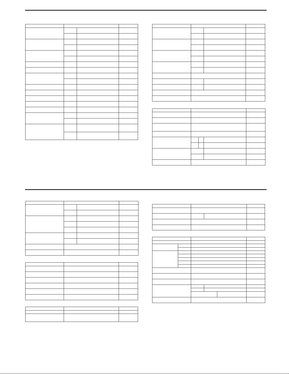
DR650SE
VALVE + GUIDE Unit: mm (in)
Valve diam.
Valve clearance
(when engine is cold)
Valve gui de to val ve stem clea rance
Valve stem deflection
Valve guide I.D.
Valve stem O.D.
Valve stem runout
Valve head thickness
Valve stem end length
Valve seat width
Valve head radial runout
Valve spring free length
(IN. & EX.)
Valve spring tension (IN. & EX.)
ITEM STANDARD LIMIT
IN.
EX.
IN.
EX.
IN.
EX.
IN. & EX. —
IN. & EX.
IN.
EX.
IN. & EX. —
IN. & EX. —
IN. & EX. —
IN. & EX.
IN. & EX. —
INNER —
OUTER —
INNER
OUTER
(5.9 – 6.7 kgf, 13.0 – 14.8 lbs)
(13.8 – 15.8 kgf, 30.4 – 34.8 lbs)
33
(1.3)
28
(1.1)
0.08 – 0.13
(0.003 – 0.005)
0.17 – 0.22
(0.0067 – 0.0087)
0.010 – 0.037
(0.0004 – 0.0015)
0.030 – 0.057
(0.0012 – 0.0022)
5.500 – 5.512
(0.2165 – 0.2170)
5.475 – 5.490
(0.2156 – 0.2161)
5.455 – 5.470
(0.2148 – 0.2154)
0.9 – 1.1
(0.035 – 0.043)
58 – 66 N
at length 27.5 mm (1.1 in)
135 – 155 N
at length 31.0 mm (1.2 in)
—
—
—
—
—
—
0.35
(0.014)
—
—
—
0.05
(0.002)
0.5
(0.02)
2.7
(0.11)
—
0.03
(0.001)
34.4
(1.35)
38.1
(1.50)
—
—
CAMSHAFT + C YLINDER HEAD Unit: mm (in)
Cam height
Camshaft journal oil clearance Right &
Camshaft journal holder I.D. Right &
Camshaft journal O.D. Right &
Camshaft runout
Rocker arm I.D.
Rocker a rm shaft O.D.
Cylinder head distortion
Cylinder head cover distortion
ITEM STANDARD LIMIT
IN.
EX.
Center
Left
Center
Left
Center
Left
IN. & EX.
IN. & EX.
33.710 – 33.750
(1.3272 – 1.3287)
33.700 – 33.740
(1.3268 – 1.3283)
0.032 – 0.066
(0.0013 – 0.0026)
0.028 – 0.059
(0.0011 – 0.0023)
22.012 – 22.025
(0.8666 – 0.8671)
17.512 – 17.525
(0.6894 – 0.6900)
21.959 – 21.980
(0.8645 – 0.8654)
17.466 – 17.484
(0.6877 – 0.6883)
—
12.000 – 12.018
(0.4724 – 0.4731)
11.973 – 11.984
(0.4714 – 0.4718)
—
—
33.410
(1.3154)
33.400
(1.3150)
0.150
(0.0059)
0.150
(0.0059)
—
—
—
—
0.10
(0.004)
—
—
0.05
(0.002)
0.05
(0.002)
CYLIN DER + PI STON + PISTO N RING Unit: mm (in)
Piston to cylinder clearance 0.020 – 0.030
Cylinder bore 100.000 – 100.015
Piston diam. 99.975 – 99.990
Cylinder distortion
Piston ring free end gap
Piston ring end ga p
Compr ession pres sure
(Automatic decomp. actuated)
ITEM STANDARD LIMIT
(0.0008 – 0.0012)
(3.9371 – 3.9376)
Measure at 21 mm (0.8 in) from the skirt end.
1st R App rox. 13.5 (0 .53)
2nd R Approx. 11.4 (0.45)
(3.9360 – 3.9366)
—
1st
2nd
Approx. 850 kPa (8.5 kgf/cm
(0.012 – 0.018)
(0.018 – 0.024)
0.30 – 0.45
0.45 – 0.60
2
, 120 psi) —
0.120
(0.0047)
Nicks or
Scratches
99.880
(3.9323)
0.05
(0.002)
10.8
(0.43)
9.1
(0.36)
0.50
(0.039)
1.00
(0.039)
19
1/8 E-03, 24, 28, 33
Piston ring to groove clearance
Piston ring groove width
Piston ring thick ness
Piston pin bore 23.002 – 23.008
Piston pin O.D. 22.996 – 23.000
CONROD + CRANKSHAFT Unit: mm (in)
Conrod small end I.D. 23.006 – 23.014
Conrod deflection
Conrod big end side clearance 0.10 – 0.65
Conrod big end width 24.95 – 25.00
Crankshaft runout
Crank web to web width 71.0 ± 0.1
OIL PUMP
Oil pump reduction ratio 1.633 (61/28 × 30/20 × 15/30) —
Oil pressure (at 60 °C, 140 °F) Above 30 kPa (0.3 kgf/cm
ITEM STANDARD LIMIT
ITEM STANDARD LIMIT
ITEM STANDARD LIMIT
1st —
2nd —
1st
2nd
Oil
1st
2nd
Below 70 kPa (0.7 kgf/cm
1.230 – 1.250
(0.048 – 0.049)
1.210 – 1.230
(0.047 – 0.048)
2.810 – 2.830
(0.110 – 0.111)
1.170 – 1.190
(0.0461 – 0.0469)
1.150 – 1.170
(0.0453 – 0.0461)
(0.9056 – 0.9058)
(0.9054 – 0.9055)
(0.9057 – 0.9061)
—
(0.004 – 0.026)
(0.982 – 0.984)
—
(2.795 ± 0.004)
at 3 000 r/min
2
, 4.3 ps i)
2
, 10.0 psi)
0.180
(0.0071)
0.150
(0.0059)
—
—
—
—
—
23.030
(0.9067)
22.980
(0.9047)
23.040
(0.9071)
3.0
(0.12)
1.00
(0.039)
—
0.05
(0.002)
—
—
2/8 E-03, 24, 28, 33
CLUTCH Unit: mm (in)
Clutch lever play 10 – 15
Drive plate thickness No. 1 &
Driven plate distortion
Clutch spring free length
DRIVE TRAIN Unit: mm (in) Except ratio
Primary reduction ratio 2.178 (61/28) —
Final reduct ion ra tio E-03, 28, 33 2.8 00 (42/15) —
Gear ra tios Low 2.416 ( 29/12) —
Shift fork to groove clearance 0.10 – 0.30
Shift fork groove width 5.0 – 5.1
Shift fork thickness 4.8 – 4.9
Drive chain Type DAIDO: D.I.D. 525V9 —
Drive c hain slack 30 – 45
ITEM STANDARD LIMIT
(0.4 – 0 .6)
No. 2
ITEM STANDARD LIMIT
E-24 2.733 (41/15) —
2nd 1. 625 (2 6/16) —
3rd 1.2 38 (26/ 21) —
4th 1.0 00 (21/21) —
Top 0. 826 (1 9/23) —
Links 110 —
20-pitch length —
2.9 – 3.1
(0.11 – 0.12)
—
—
(0.004 – 0.012)
(0.197 – 0.200)
(0.189 – 0.193)
(1.2 – 1.8)
—
2.6
(0.10)
0.10
(0.004)
33.0
(1.30)
0.50
(0.020)
—
—
319.4
(12.57)
—
3/8 E-03, 24, 28, 33
4/8 E-03, 24, 28, 33
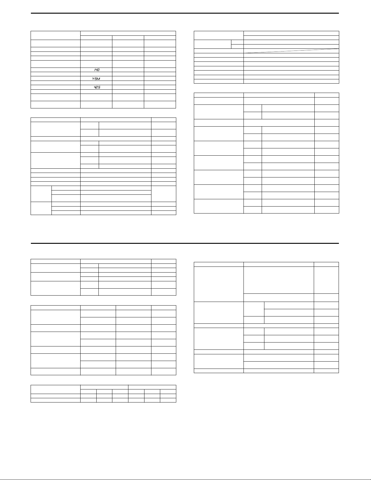
20
CARBURETOR
ITEM
Carburetor type MIKUNI
Bore size 40 mm ←←
I.D. No. 32E1 32E6 32E3
Idle r/min 1 500 ± 100 r/min ←←
Float height 14.7 ± 1.0 mm
Main jet (M.J. ) # ← #140
Jet needle (J.N.) 6F23 ← 6F19-3rd
Needle jet (N.J.) ← Y- 5
Throttle valve (Th.V.) #95 ←←
Pilot jet (P.J.) # ← #42.5
Starter jet (S.J.) #40 ←←
Pilot screw (P.S.)
Throt tle ca ble play
(pulling cable)
E-03, 28 E-33 E-24
BST40SS
(0.58 ± 0.04 in)
PRE-SET ←
2.0 – 4.0 mm
(0.08 – 0.16 in)
ELECTRICAL
Spark plug
Spark performance Over 8 (0.3) at 1 atm.
Ignition coil resistance Primary 0.07 – 0.12 Ω B – B/W
Generator coil resistance Charging 0.5 – 0.9 Ω Y – Y
Gener ator no -load voltage Mo re than 75 V (AC) at 5 000 r/ min
Generator Max. output Approx. 200 W at 5 000 r/min
Regulated voltage 13.0 – 16.0 V at 5 000 r/min
Starter relay resistance 3 – 5 Ω
Battery Type designation YTX9-BS
Fuse size Main 30 A
ITEM SPECIFICATION NOTE
Capacity 12 V 28.8 kC (8 Ah)/10 HR
Standard
electrolyte S.G.
Headlight (H) 10 A
Head light (L) 10 A
Type
Gap
Secondary 23 – 25 kΩ
Power
source
Pick-up 170 – 256 Ω Bl – G
SPECIFICATION
←←
←←
←←
ND.: U31ESR-N
N.G.K.: CR10E
0.7 – 0.8
(0.028 – 0.031)
0.1 – 0.2 Ω B – W
1.320 at 20 °C (68 °F)
PRE-SET
(1.0 turn back)
Unit: mm (in)
Plug cap –
Plug cap
WATTAGE Unit: W
ITEM
Headlight HI 60
Parkin g or positi on lig ht
Brake light/Taillight 21/5
Turn signal light 21
Speedometer light 1.7
Turn signal indicator light 2
High beam indicator light 2
Neutral indicator light 2
License light 5
LO 55
SPECIFICATION
E-03, 24, 28, 33
BRAKE + WHEEL Unit: mm (in)
Rear brake pedal height 5
Brake disc thickness
Brake disc runout
Master cylinder bore
Master cylinder piston diam.
Brake caliper cylinder bore
Brake caliper piston diam.
Wheel rim runout
Wheel axle runout
ITEM STANDARD LIM IT
(0.2)
Front
Rear
Front
Rear
Front
Rear
Front
Rear
Front
Rear
Axial —
Radial —
Front —
Rear —
4.0 ± 0. 2
(0.1 57 ± 0.008)
4.5 ± 0. 2
(0.1 77 ± 0.008)
—
12.700 – 12.743
(0.5000 – 0.5017)
12.700 – 12.743
(0.5000 – 0.5017)
12.657 – 12.684
(0.4983 – 0.4994)
12.657 – 12.684
(0.4983 – 0.4994)
27.000 – 27.050
(1.0630 – 1.0650)
30.23 – 30.28
(1.1902 – 1.1921)
26.90 – 26.95
(1.0591 – 1.0610)
30.16 – 30.18
(1.1874 – 1.1882)
—
3.5
(0.14)
4.0
(0.16)
0.30
(0.012)
—
—
—
—
—
—
—
—
2.0
(0.08)
2.0
(0.08)
0.25
(0.010)
0.25
(0.010)
5/8 E-03, 24, 28, 33
Tire rim size Front 21 × 1.85 —
Tire size Front 90/90-21M/C 54S —
Tire tread depth
ITEM
Rear 17M/C × MT2.50 —
Rear 120/ 90-17M /C 64S —
Front —
Rear —
STANDARD
LIMIT
3.0
(0.12)
3.0
(0.12)
SUSPENSION Unit: mm (in)
Front fork stroke 260
Front fork spring free length
Front fork oil level 164
Rear shock absorber spring pre-set
length
Rear wheel travel 260
Swingarm pivot shaft runout
ITEM STANDARD LIMIT NOTE
(10.2)
220
(8.7)
—
(6.5)
150
(5.9)
247.5
(9.74)
(10.2)
220
(8.7)
—
—
— Low seat
548
(21.6)
—
— Low seat
—
—
— Low seat
0.3
(0.01)
TIRE PRESSURE
COLD INFLATION
TIRE PRESSURE
FRONT 1 50 1.50 22 175 1.75 25
REAR 175 1.75 25 200 2.00 29
SOLO RIDIN G DUAL RIDING
2
kPa kgf/cm
psi kPa kgf/cm2psi
6/8 E-03, 24, 28, 33
FUEL + OIL
Fuel type Use only unleaded gasoline of at least 87 pump
Fuel tank capacity
Engine oil type SAE 10W-40, API SF or SG
Engine oil capac ity
Front fork oil type Fork oil #10
Front fork oil capacity (each leg) 565 ml
Brake fluid type DOT 4
ITEM SPECIFICATION NOTE
octane (R/2 + M/2) or 91 octane or higher rated by
the reserch method.
Gasoline containing MTBE (MethyI Tertiary ButyI
Ether), less than 10% ethanol, or less than 5%
methanol with appropriate cosolvents and corrosion inhibitor is permissible.
Gasoline used should be graded 91 octane or
higher. An unleaded gasoline is recommended.
Including
reserve
Only reserve
Oil change
Oil and
filter change
Engine
overhaul
(19.1 /19.9 U S/lmp o z)
(19.0/19.8 US/Imp oz)
12 L
(3.2/2.6 US/Imp gal)
13 L
(3.4/2.9 US/Imp gal)
3.0 L
(0.8/0.7 US/Imp gal)
2 300 ml
(2.4/2.0 US/lmp qt)
2 400 ml
(2.5/2.1 US/lmp qt)
2 600 ml
(2.7/2.3 US/lmp qt)
563 ml
E-03, 28, 33
E-24
E-33
Others
Low seat
7/8 E-03, 24, 28, 33
8/8 E-03, 24, 28, 33
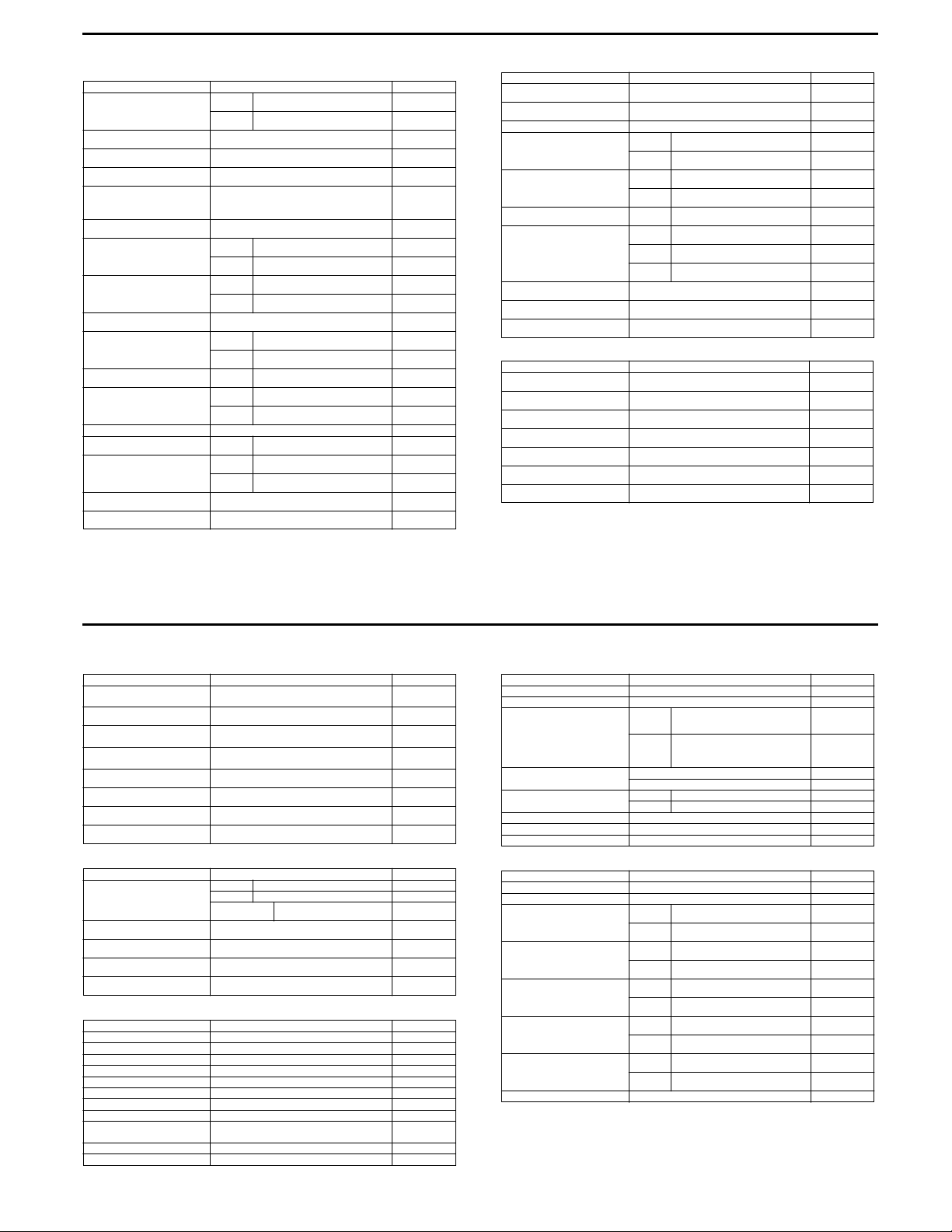
DR-Z110
ENGINE TOP END Unit: mm (in)
Cam height
Camshaft chain 20-link length 127.00 – 127.48
Rocker arm inside diameter 10.000 – 10.015
Rocker arm shaft diameter 9.980 – 9.995
Cylinder compression Usable range
Cylinder head warp
Valve clearance
Valve head thickness
Valve stem bend
Valve stem diameter
Valve guide inside diameter
Valve/valve guide clearance
(Wobble m ethod)
Valve seat cutting angle 45°, 32°, 60°, 67.5° —
Valve seat width
Valve seat surface outside diameter
Valve spring free length 36.75
Cylinder inside diameter 52.997 – 53.009
ITEM STANDARD LIMIT
IN.
EX.
(8.8 – 13.5 kgf/cm
IN.
EX.
IN.
EX.
IN.
EX.
IN. & EX.
IN.
EX.
IN. & EX.
IN.
EX.
28.984 – 29.164
(1.1411 – 1.1482)
29.021 – 29.201
(1.1426 – 1.1496)
(5.000 – 5.014)
(0.3937 – 0.3943)
(0.3929 – 0.3935)
865 – 1 320 kPa
2
, 125 – 192 psi)
at 5 kick s
—
0.04 – 0.08
(0.0016 – 0.0031)
0.04 – 0.08
(0.0016 – 0.0031)
0.85 – 1.15
(0.0335 – 0.0453)
1.15 – 1.45
(0.0453 – 0.0571)
TIR 0.01 (0.0004) or less
4.475 – 4.490
(0.1762 – 0.1768)
4.462 – 4.472
(0.1757 – 0.1761)
4.500 – 4.512
(0.1772 – 0.1776)
0.02 – 0.07
(0.0008 – 0.0028)
0.06 – 0.11
(0.002 – 0.004)
0.80 – 1.15
(0.0315 – 0.0453)
22.9 – 23.1
(0.902 – 0.909)
19.9 – 20.1
(0.784 – 0.791)
(1.447)
(2.0865 – 2.0870)
28.88
(1.137)
28.92
(1.139)
128.9
(5.075)
10.05
(0.396)
9.95
(0.392)
—
0.05
(0.002)
—
—
0.5
(0.02)
0.5
(0.02)
TIR 0.05
(0.002)
4.46
(0.176)
4.44
(0.175)
4.55
(0.179)
0.12
(0.0047)
0.19
(0.007)
—
—
—
35.5
(1.40)
53.10
(2.091)
Piston outside di ameter 52.981 – 52.993
Piston/cylinder clearance 0.010 – 0.022
Oversize piston and rings +0.50 (0.0197), +1.0 (0.0394) —
Piston ring/gro ove cle arance
Piston ring groove width
Piston ring thickness Top &
Piston ring end ga p
Piston pin diameter 12.995 – 13.000
Piston pin hole ins ide diame ter 13. 001 – 13.00 7
Connecting rod small end inside
diameter
CRANKSHAFT/TRANSMISSION Unit: mm (in)
Connecting rod big end radial
clear ance
Connecting rod big end side clearance
Crankshaft runout
Shift fork ear thickness 3.9 – 4.0
Gear s hift for k groove widt h 4.05 – 4.15
Shift fork guide pin diameter 4.9 – 5.0
Shift drum groove width 5.05 – 5.20
ITEM STANDARD LIMIT
(2.0859 – 2.0863)
(0.0004 – 0.0009)
Top
Second
Top
Second
Second
Top
Second
Oil
ITEM STANDARD LIMIT
Less than 0.03 mm (0.001 in) TIR
0.02 – 0.06
(0.0008 – 0.0024)
0.01 – 0.05
(0.0004 – 0.0020)
0.81 – 0.83
(0.0319 – 0.0327)
0.80 – 0.82
(0.0315 – 0.0323)
0.77 – 0.79
(0.0303 – 0.0311)
0.15 – 0.30
(0.0059 – 0.0118)
0.30 – 0.45
(0.0118 – 0.0177)
0.10 – 0.60
(0.0039 – 0.0236)
(0.5116 – 0.5118)
(0.5118 – 0.5121)
13.003 – 13.014
(0.5119 – 0.5124)
0.006 – 0.020
(0.0002 – 0.0008)
0.1 – 0.2
(0.004 – 0.008)
(0.154 – 0.157)
(0.159 – 0.163)
(0.193 – 0.197)
(0.199 – 0.205)
52.83
(2.080)
—
0.16
(0.0063)
0.15
(0.0059)
0.90
(0.035)
0.90
(0.035)
0.7
(0.028)
0.6
(0.024)
0.8
(0.032)
0.9
(0.035)
12.96
(0.5102)
13.07
(0.5146)
13.05
(0.5138)
0.07
(0.0028)
0.4
(0.016)
0.08
(0.003)
3.8
(0.15)
4.3
(0.17)
4.8
(0.19)
5.3
(0.21)
21
1/5 P-19, 24, 28, 33
CLUTCH Unit: mm (in)
Primary clutch housing inside
diameter
Primary clutch shoe groove depth 1.0
Secondary clutch friction plate
thickness
Secondary clutch friction plate
war p
Secondary clutch steel plate warp
Clutch spring free length 22.04
Kick shaft diameter 15.941 – 15.968
Kick gear inside diameter 16.000 – 16.018
ITEM STANDARD LIMIT
104.0 – 104.2
(4.094 – 4.102)
(0.04)
3.1 – 3 .3
(0.12 – 0.13)
0.2 mm (0.008 in) or less
0.15 mm (0.006 in) or less
(0.87)
(0.6276 – 0.6287)
(0.6299 – 0.6306)
104.5
(4.114)
0.5
(0.02)
2.9
(0.11)
0.3
(0.01)
0.3
(0.01)
20.35
(0.80)
15.92
(0.6268)
16.04
(0.6315)
FINAL DRIVE Unit: mm (in)
Drive chain Type DAI DO: D.I.D. 420MBK1 —
Drive c hain slack 0 – 5
Engline sprocket diameter 49.1 – 49.3
Rear sprocket diameter 126.24
Rear spr ocket warp
ITEM STANDARD LIMIT
Links 86 links —
20-link length
Less t han 0.4 mm (0.016 i n)
254.0 – 254.6
(10.00 – 10.02)
(0 – 0.2)
(1.93 – 1.94)
(4.97)
259
(10.20)
—
48.4
(1.91)
125.4
(4.94)
0.5
(0.020)
FUEL SYSTEM Unit: mm (in)
Throttole grip free play 2 – 3 (0.08 – 0.12) —
Carbur etor t ype KEIHIN PB18 —
Main jet #80 —
Jet needle NCFA —
Throttle valve cutaway 3.0 —
Pilot jet #38/38 —
Air screw 1 and 1/4 turns out —
Idle speed 1 250 – 1 350 r/min (rpm) —
Servise fuel level (below the bottom
edge of carburetor body)
Float height 10.7 ± 2 (0.42 ± 0.08) —
Air cleaner element oil High quality foam air filter oil —
ITEM STANDARD LIMIT
3.0 ± 1 (0.12 ± 0.04) —
2/5 P-19, 24, 28, 33
ELECTRICAL SYSTEM Unit: mm (in)
Pickup coil resistance 50 – 200 Ω B l/Y – G round
Air gap 0.7 (0.028) —
Ignition coil Primary
Excite r coil resi stance 0.2 – 1.0 Ω W – Ground
Spark plug type NGK CR6HSA —
Ignition coil (primary) peak voltage 100 V or above —
Pickup coil peak voltage 4.6 V or above —
Exciter coil peak voltage 15 V or above —
ITEM STANDARD NOTE
winding
resistance
Second-
ary wi nd-
ing
resistance
gap 0.6 – 0.7 (0.024 – 0.028) —
0.19 – 0.23 Ω —
2.5 – 3.7 kΩ —
0.1 – 0 .8 Ω Y – Ground
BRAKES Unit: mm (in)
Brake lever free play 4 – 5 (0.16 – 0.20) —
Brake pedal free play 20 – 30 (0.79 – 1.18) —
Brake shoe lining thickness
Brake shoe spring free length
Brake drum inside diameter
Brake camshaft diameter
Brake ca mshaft ho le insi de diameter
Brake cam lever angle 80 – 90° —
ITEM STANDARD LIMIT
Front
Rear
Front
Rear
Front
Rear
Front
Rear
Front
Rear
2.10 – 3.00
(0.08 – 0.12)
3.85 – 4.15
(0.152 – 0.163)
30.8 – 31.2
(1.213 – 1.228)
32.5
(1.280)
90.000 – 90.087
(3.543 – 3.547)
110.000 – 110.087
(4.331 – 4.334)
11.957 – 11.984
(0.471 – 0.472)
14.957 – 14.984
(0.589 – 0.590)
12.000 – 12.027
(0.472 – 0.474)
15.000 – 15.027
(0.591 – 0.592)
1.2
(0.05)
2.0
(0.08)
32.6
(1.28)
34.1
(1.34)
90.75
(3.57)
110.75
(4.36)
11.88
(0.468)
14.88
(0.586)
12.15
(0.478)
15.15
(0.596)
3/5 P-19, 24, 28, 33
4/5 P-19, 24, 28, 33
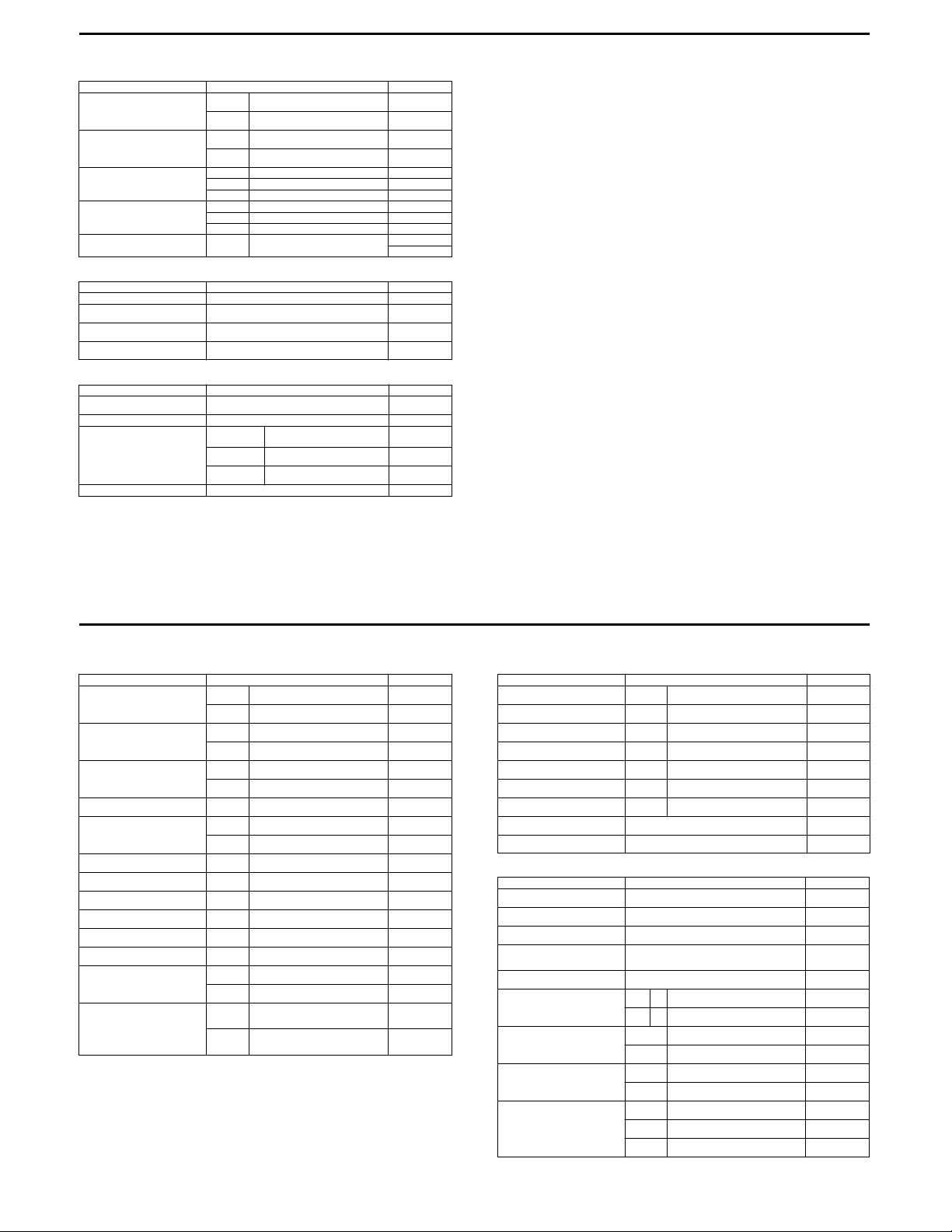
22
WHEELS/TIRES Unit: m m (in)
Wheel rim runout (Front & Rear)
Axle runout Front
Front tire Size 2.50-14MC 4PR —
Rear tire Size 3.00-12 4PR —
Tire air pressure
ITEM STANDARD LIMIT
Axial 0.5 mm (0.02 in) or less
Radial 0.8 mm (0.03 in) or less
(/100 mm)
Rear
(/110 mm)
Make CH ENG SHIN —
Type C803 —
Make CH ENG SHIN —
Type C803 —
Front &
Rear
0.1 (0.004)
0.1 (0.004)
100 kPa
(1.0 kgf/cm
2
, 14 psi)
(0.08)
(0.08)
0.2
(0.008)
0.2
(0.008)
—
—
2
2
SUSPENSIONS Unit: mm (in)
Front fork oil viscosity SS-8 or SAE 10W-20 —
Front fork oil capacity
(completely dry)
Front fork oil level
(fully compressed, spring removed)
Front fork spring free length 439.7
ITEM STAN DARD LIMIT
163 ± 2.5 ml
(5.51 ± 0.08 US oz)
89 ± 2 (3.50 ± 0.08)
from top of inner tube
(17.31)
—
—
430.9
(16.96)
ENGINE OIL Unit: mm (in)
Engine oil type API SE, SF or SG
Engine oil viscosity SAE 10W-40 —
Engine oil capacity When engine is
Engine oil level Between upper and lower level lines —
ITEM STANDA RD LIMIT
API SH or SJ with JASO MA
completely dry
When filter is
removed
When filter is
not removed
1.1 L (1.2 US qt) —
1.0 L (1.1 US qt) —
0.9 L (1.0 US qt) —
—
5/5 P-19, 24, 28, 33
DR-Z125/L
VALVE + GUIDE Unit: mm (in)
Valve diam.
Valve clearance (when cold)
Valve gui de to val ve stem
clear ance
Valve guide I.D.
Valve stem O.D.
Valve stem deflection
Valve stem runout
Valve head thickness
Valve stem end length
Valve seat width
Valve head radial runout
Valve spring free length
(IN. & EX.)
Valve spring tension
(IN. & EX.) INNER
ITEM STANDARD LIMIT
IN.
EX.
IN.
EX.
IN.
EX.
IN. & EX.
IN.
EX.
IN. & EX. —
IN. & EX. —
IN. & EX. —
IN. & EX. —
IN. & EX.
IN. & EX. —
INNER —
OUTER —
(7.8 – 9.2 kgf, 17.2 – 20.3 lbs)
OUTER
(18.9 – 22.3 kgf, 41.7 – 49.2 lbs)
30
(1.2)
26
(1.0)
0.08 – 0.13
(0.003 – 0.005)
0.13 – 0.18
(0.005 – 0.007)
0.010 – 0.037
(0.0004 – 0.0015)
0.030 – 0.057
(0.0012 – 0.0022)
5.500 – 5.512
(0.2165 – 0.2170)
5.475 – 5.490
(0.2156 – 0.2161)
5.455 – 5.470
(0.2148 – 0.2154)
0.9 – 1.1
(0.035 – 0.043)
76 – 90 N
at len gth 32. 5 mm ( 1.28 in )
186 – 219 N
at len gth 36. 0 mm ( 1.42 in )
—
—
—
—
—
—
—
—
—
0.35
(0.014)
0.05
(0.002)
0.5
(0.014)
2.5
(0.10)
—
0.03
(0.001)
36.0
(1.42)
39.3
(1.55)
—
—
CAMSHAFT + C YLINDER HEAD Unit: mm (in)
Cam height
Camshaft journal oil clearance
Camsh aft jo urnal holder I.D.
Camsh aft jo urnal O.D.
Camshaft runout
Rocker arm I.D.
Rocker ar m shaft O.D.
Cylinder head distortion
Cylinder head cover distortion
CYLIN DER + PI STON + PISTO N RING Unit: mm (in)
Compression pressure 1 200 – 1 600 kPa
Piston to cylinder clearance 0.020 – 0.030
Cylinder bore 57.000 – 57.015
Piston diam. 56.975 – 56.990
Cylinder distortion
Piston ring free end gap
Piston ring end ga p
Piston ring to gr oove cle arance
Piston ring groove width
ITEM STANDARD LIMIT
IN. & EX.
IN. & EX.
IN. & EX.
IN. & EX.
IN. & EX. —
IN. & EX.
IN. & EX.
ITEM STANDARD LIMIT
(12 – 16 kgf/cm
Measure at 12 mm (0.5 in) from the skirt end.
1st R Approx. 7.0 (0.28)
2nd R Approx. 8.5 (0.33)
1st
2nd
1st —
2nd —
1st
2nd
Oil
33.13 – 33.17
(1.304 – 1.306)
0.032 – 0.066
(0.0013 – 0.0026)
22.012 – 22.025
(0.8666 – 0.8671)
21.959 – 21.980
(0.8645 – 0.8654)
12.000 – 12.018
(0.4724 – 0.4731)
11.977 – 11.995
(0.4715 – 0.4722)
—
—
2
, 171 – 228 psi)
(0.0008 – 0.0012)
(2.2440 – 2.2447)
(2.2431 – 2.2437)
—
0.10 – 0.25
(0.004 – 0.010)
0.10 – 0.25
(0.004 – 0.010)
1.21 – 1.23
(0.047 – 0.048)
1.21 – 1.23
(0.047 – 0.048)
2.51 – 2.53
(0.099 – 0.100)
32.83
(1.29)
0.150
(0.0059)
—
—
0.10
(0.004)
—
—
0.05
(0.002)
0.05
(0.002)
1 000 kPa
(10 kgf/cm2, 142 psi )
0.120
(0.0047)
57.110
(2.2484)
56.880
(2.2394)
0.05
(0.002)
5.6
(0.22)
6.8
(0.27)
0.5
(0.02)
0.5
(0.02)
0.18
(0.007)
0.15
(0.006)
—
—
—
1/7 E-28, 33
2/7 E-28, 33
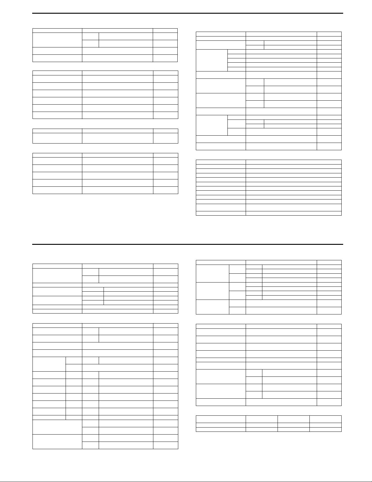
23
Piston ring thick ness
Piston pin bore 14.002 – 14.008
Piston pin O.D. 13.994 – 14.002
ITEM STANDARD LIMIT
1st
2nd
1.175 – 1.190
(0.0463 – 0.0469)
1.170 – 1.190
(0.0461 – 0.0469)
(0.5513 – 0.5515)
(0.5509 – 0.5513)
—
—
14.030
(0.5524)
13.980
(0.5504)
CONROD + CRANKSHAFT Unit: mm (in)
Conrod small end I.D. 14.004 – 14.012
Conrod deflection
Conrod big end side clearance 0.10 – 0.45
Conrod big end width 15.95 – 16.00
Crank web to web width 53.0 ± 0.1
Crankshaft runout
ITEM STANDARD LIMIT
(0.5513 – 0.5517)
—
(0.004 – 0.018)
(0.628 – 0.630)
(2.09 ± 0.004)
—
14.040
(0.5528)
3.0
(0.12)
1.0
(0.04)
—
—
0.08
(0.003)
OIL PUMP
Oil pressure (at 60°C, 140°F) Above 15 kPa (0.15 kgf/cm
ITEM STANDARD LIMIT
Below 35 kPa (0.35 kgf/cm
at 3 000 r/min
CLUTCH
Clutch lever play 10 – 15
Drive plate thickness 2.90 – 3.10
Drive plate claw width 11.8 – 12.0
Driven plate distortion
Clutch spring free length 32.6
ITEM STANDARD LIMIT
(0.4 – 0 .6)
(0.114 – 0.122)
(0.46 – 0.47)
—
(1.28)
2
, 2.1 psi)
2
, 4.9 ps i)
—
Unit: mm (in)
—
2.60
(0.102)
11.5
(0.45)
0.10
(0.004)
31.0
(1.22)
DRIVE TRAIN + DRIVE CHAIN Unit: mm (in) Except ratio
Primary reduction ratio 3.470 (59/17) —
Final reduction ratio DR-Z125 3.642 (51/14) —
Gear ratios Low 3.000 (33/11) —
Shift fork to groove clearance 0.10 – 0.30
Shift fork groove width
Shift fork thickness
Countershaft length
(Low to 2nd)
Drive chain Type D.I.D. 428HG —
Drive chain slack 35 – 45
Gearshift lever height 5 – Above 5
ITEM STANDARD LIMIT
DR-Z125L 4.071 (57/14) —
2nd 1.857 (26/14) —
3rd 1.368 (26/19) —
4th 1.095 (23/21) —
Top 0.923 (24/26) —
(0.004 – 0.012)
No. 1
No. 2
No. 1
No. 2
DR-Z125 122 —
Links
DR-Z125L 130 —
20-pitch
length
5.0 – 5.1
(0.196 – 0.201)
5.5 – 5.6
(0.217 – 0.224)
4.8 – 4.9
(0.189 – 0.193)
5.3 – 5.4
(0.209 – 0.213)
+0.1
3.46
88.0
-0
(
—
(1.4 – 1 .8)
(0.2 – Above 0.2)
+0.004
-0
)
0.50
(0.02)
—
—
—
—
—
259.0
(10.20)
—
—
CARBURETOR
Carbur etor t ype MI KUNI VM20S S
Bore size 20 mm (0 .8 in)
I.D. No. 0 8G0
Idle r/min 1 700 ± 100 r/min
Float height 18.9 ± 1.0 mm (0.74 ± 0.04 in)
Main jet (M.J.) #102.5
Jet needle (J.N.) 5HGM74-1
Needle jet (N.J.) N-6M
Pilot jet (P.J.) #17.5
Pilot screw
Throt tle ca ble play 2.0 – 4. 0 mm (0. 08 – 0.16 in)
ITEM SPECIFICATION
(P.S.)
PRE-SET
(2 and 1/4 turns back)
3/7 E-28, 33
ELECTRICAL
Spark plug
Spark performance Over 8 mm (0.3 in) at 1 atm.
Ignition coil resistance Primary 0.1 – 0.8 Ω W/Bl – B/W
Generator coil resistance Charging 13 – 22 Ω Y – Y/R
Pick-up coil peak voltage More than 2.0 V
Ignition coil primary peak voltage More than 150 V : B /W, : W/Bl
BRAKE + WHEEL
Brake lever play
Front brake cable play
Rear brake pedal free travel 20 – 30
Rear brake pedal height 10 – 0
Brake drum I.D.
Brake disc thickness
Brake disc runout
Master cylinder bore
Master cylinder piston
diam.
Brake caliper cylinder
bore
Brake caliper piston
diam.
Brake fluid type Front DR-Z125L DOT 4 —
Wheel rim runout
Wheel axle runout
ITEM SPECIFICATION NOTE
Type
Gap
Secondary 13 – 18 kΩ Plug cap – W/Bl
Pick-up coil 140 – 230 Ω G – B/W
ITEM STANDARD/SPECIFICATION LIMIT
DR-Z125
DR-Z125
Front DR-Z125 —
Rear —
Front DR-Z125L
Front DR-Z125L —
Front DR-Z125L
Front DR-Z125L
Front DR-Z125L
Front DR-Z125L
Axial —
Radial —
Front —
Rear —
DENSO: X24ESR-U
NGK: DR8EA
0.6 – 0.8 mm
(0.024 – 0.031 in)
0.1 – 0.3
(0.004 – 0.012)
15 – 25
(0.6 – 1.0)
(0.8 – 1 .2)
(0.4 – 0)
3.5 ± 0.2
(0.14 ± 0.008)
11.000 – 11.043
(0.4331 – 0.4348)
10.957 – 10.984
(0.4314 – 0.4324)
30.230 – 30.306
(1.1902 – 1.1931)
30.150 – 30.200
(1.1870 – 1.1890)
: G, : B/W
Unit: mm (in)
—
—
—
—
110.7
(4.36)
110.7
(4.36)
3.0
(0.12)
0.30
(0.012)
—
—
—
—
2.0
(0.08)
2.0
(0.08)
0.25
(0.010)
0.25
(0.010)
4/7 E-28, 33
Wheel rim size
Tire size
Tire tread depth
ITEM STANDARD/SPECIFICATION LIMIT
DR-Z125 J17 × 1.40 —
Front
DR-Z125L J19 × 1.40 —
DR-Z125 J14 × 1.60 —
Rear
DR-Z125L J16 × 1.60 —
DR-Z1 25 70/ 100-17 40M —
Front
DR-Z125L 70/100-19 42M —
DR-Z1 25 90/ 100-14 49M —
Rear
DR-Z125L 90/100-16 52M —
Front —
Rear —
4.0
(0.16)
4.0
(0.16)
SUSPENSION Unit: mm (in)
Front fork stroke 180
Front fork spring free length 599.1
Front fork oil level 173
Front fork oil type SUZUKI FORK OIL SS-08 (#10) or
Front fork oil capacity (each leg) 172 ml (4.3/4.5 US/lmp oz) —
Front fork inner tube O.D. 30
Rear shock absorber spring
pre-set length
Rear wheel travel
Swingarm pivot shaft runout
ITEM STANDARD/SPECIFICATION LIMIT
(7.1)
(23.59)
(6.8)
an equivalent fork oli
(1.2)
DR-Z125
DR-Z125L
DR-Z125
DR-Z125L
240.5
(9.47)
241.1
(9.49)
160
(6.3)
170
(6.7)
—
—
587
(23.1)
—
—
—
—
—
—
—
0.6
(0.02)
TIRE PRESSURE
COLD INFLATION
TIRE PRESSURE
FRONT 100 1.0 14
REAR 100 1.0 14
kPa kgf/cm
2
psi
5/7 E-28, 33
6/7 E-28, 33
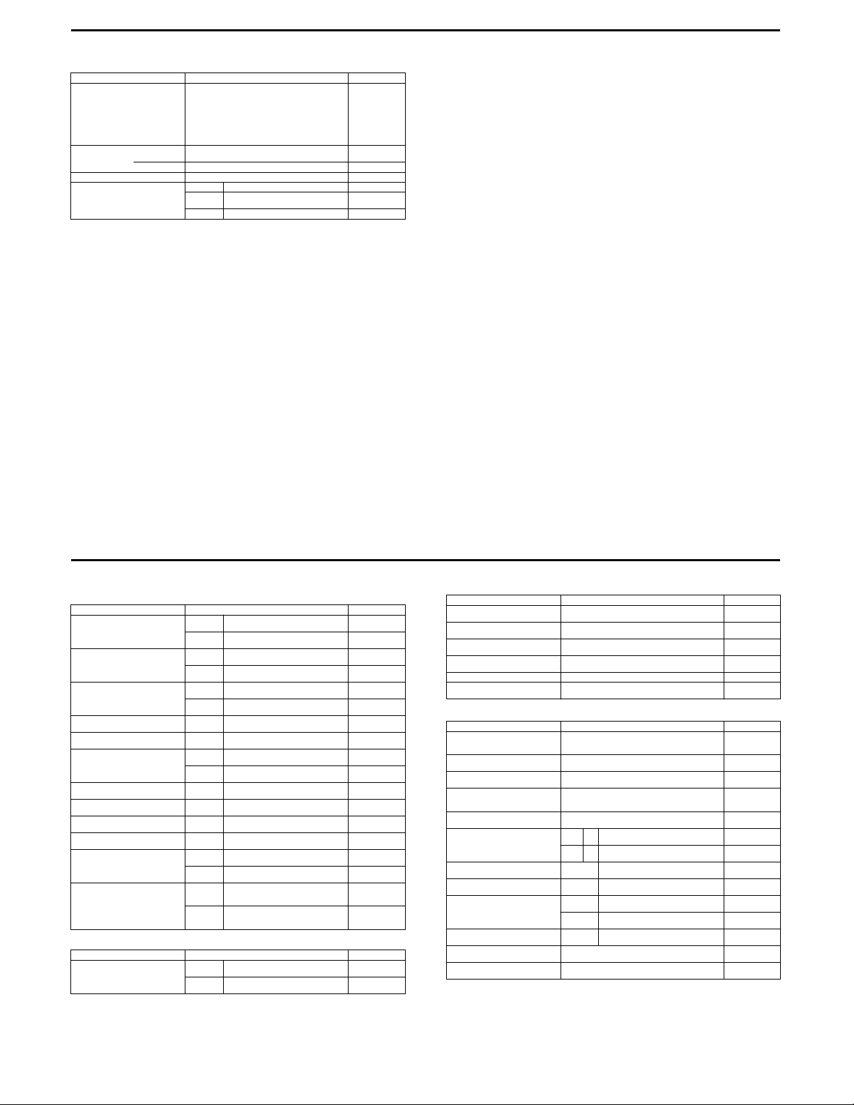
24
FUEL + OIL
Fuel type Use only unleaded gasoline of at least 87 pump
Fuel tank capacity including
Engine oil type SAE 10 W-40, API SF or SG
Engine oil capacity Change 850 ml (0.9/0.7 US/lmp qt)
ITEM SPECIFICATION NOTE
octane (R/2 + M/2) or 91 octane or higher rated by
the research method.
Gasoline containing MTBE (Methyl Tertiary Butyl
Ether), less than 10% ethanol, or less than 5%
methanol with appropriate cosolvents and corrosion inhibitor is permissible.
reserve
reserve 1.7 L (0.4/0.4 US/lmp qt)
6.6 L (1.7/1.5 US/lmp qt)
Filter
change
Overhaul 1 100 ml (1.2/1.0 US/lmp qt)
950 ml (1.0/0.8 US/lmp qt)
7/7 E-28, 33
DR-Z250 (E-03, 28, 33)
VALVE + GUIDE Unit: mm (in)
Valve diam.
Tappet clearance (when cold)
Valve gui de to val ve stem
clear ance
Valve stem deflection
Valve guide I.D.
Valve stem O.D.
Valve stem runout
Valve head thickness
Valve seat width
Valve head radial runout
Valve spring free length
(IN. & EX.)
Valve spring tension
(IN. & EX.) INNER
CAMSHAFT + C YLINDER HEAD Unit: mm (in)
Cam height
ITEM STANDARD LIMIT
ITEM STANDARD LIMIT
IN.
EX.
IN.
EX.
IN.
EX.
IN. & EX. —
IN. & EX.
IN.
EX.
IN. & EX. —
IN. & EX. —
IN. & EX.
IN. & EX. —
INNER —
OUTER —
OUTER
(13.3 – 15.3 kgf, 29.3 – 33.7 lbs)
IN.
EX.
28.5
(1.12)
25.0
(0.98)
0.10 – 0.20
(0.004 – 0.008)
0.20 – 0.30
(0.008 – 0.012)
0.010 – 0.037
(0.0004 – 0.0015)
0.030 – 0.057
(0.0012 – 0.0022)
4.500 – 4.512
(0.1772 – 0.1776)
4.475 – 4.490
(0.1762 – 0.1768)
4.455 – 4.470
(0.1754 – 0.1760)
0.9 – 1.1
(0.035 – 0.043)
48 – 58 N
(4.8 – 5.8 kgf, 10.6 – 12.8 lbs)
at len gth 29. 9 mm ( 1.18 in )
133 – 153 N
at length 33.4 mm (1.32 in)
35.32 – 35.36
(1.391 – 1.392)
35.22 – 35.26
(1.387 – 1.388)
—
—
—
—
—
—
0.35
(0.014)
—
—
—
0.05
(0.002)
0.5
(0.02)
—
0.03
(0.001)
38.6
(1.52)
40.6
(1.60)
—
—
35.02
(1.379)
34.92
(1.375)
Camsh aft jo urnal oil clearan ce 0. 032 – 0.066
Camshaft journal holder I.D. 22.012 – 22.025
Camshaft journal O.D. 21.959 – 21.980
Camshaft runout
Cam chain pin (at arrow “3”) 17th pin —
Cylinder head distortion
ITEM STANDARD LIMIT
(0.0013 – 0.0026)
(0.8666 – 0.8671)
(0.8645 – 0.8654)
—
—
0.150
(0.0059)
—
—
0.10
(0.004)
0.05
(0.002)
CYLIN DER + PI STON + PISTO N RING Unit: mm (in)
Compr ession pres sure
Piston to cylinder clearance 0.015 – 0.025
Cylinder bore 73.000 – 73.015
Piston diam. 72.980 – 72.995
Cylinder distortion
Piston ring free end gap
Piston ring end ga p
Piston ring to groove clearance
Piston ring groove width
Piston ring thick ness
Piston pin bore 19.002 – 19.008
Piston pin O.D. 18.992 – 19.000
ITEM STANDARD LIMIT
Measure at 15 mm (0.6 in) from the skirt end.
1st R Approx. 7.6 (0.30)
2nd R Approx. 7.7 (0.31)
1st & 2nd
1st & 2nd —
1st & 2nd
Oil
1st & 2nd
1 300 kPa
2
, 185 psi)
(13 kgf/cm
(0.0006 – 0.0010)
(2.8740 – 2.8746)
(2.8732 – 2.8738)
—
0.08 – 0.20
(0.003 – 0.008)
1.01 – 1.03
(0.040 – 0.041)
2.01 – 2.03
(0.079 – 0.080)
0.97 – 0.99
(0.038 – 0.039)
(0.7481 – 0.7483)
(0.7477 – 0.7480)
910 kPa
(9.1 kgf/cm2,
129 psi)
0.120
(0.0047)
Nicks or
scratches
72.880
(2.8693)
0.05
(0.002)
6.1
(0.24)
6.2
(0.25)
0.50
(0.02)
0.180
(0.007)
—
—
—
19.030
(0.7492)
18.980
(0.7472)
1/7 E-03, 28, 33
2/7 E-03, 28, 33
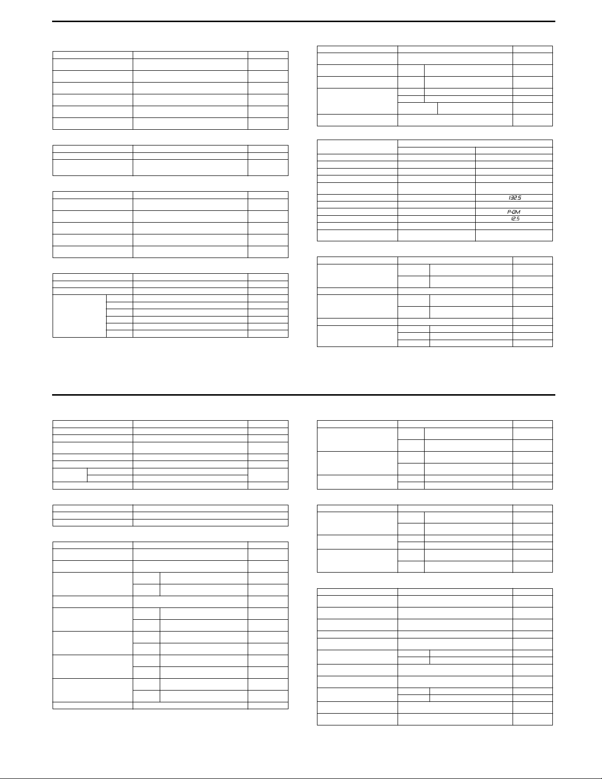
25
CONROD + CRANKSHAFT Unit: mm (in)
Conrod small end I.D. 19.006 – 19.014
Conrod deflection
Conrod big end side clearance 0.10 – 0.55
Conrod big end width 19.95 – 20.00
Crank web to web width 64.0 ± 0.1
Crankshaft runout
ITEM STANDARD LIMIT
(0.7483 – 0.7486)
—
(0.004 – 0.022)
(0.785 – 0.787)
(2.52 ± 0.004)
—
19.040
(0.7496)
3.0
(0.12)
1.0
(0.04)
—
—
0.08
(0.003)
OIL PUMP
Oil pump reduction ratio 1.571 (33/21) —
Oil pressure (at 60 °C, 140 °F) Above 50 kPa (0.5 kgf/cm
CLUTCH
Clutch lever play 10 – 15
Drive plate thickness 2.92 – 3.08
Drive plate claw width 13.7 – 13.8
Driven plate distortion
Clutch spring free length
ITEM STANDARD LIMIT
2
, 7.1 psi)
2
Below 150 kPa (1.5 kgf/cm
at 3 000 r/min
ITEM STANDARD LIMIT
(0.4 – 0 .6)
(0.115 – 0.121)
(0.539 – 0.543)
, 21.3 psi)
—
—
—
Unit: mm (in)
—
2.62
(0.103)
12.9
(0.51)
0.10
(0.004)
39.0
(1.54)
TRANSMISSION + DRIVE CHAIN Unit: mm (in) Except ratio
Primary reduction ratio 3.190 (67/21) —
Final reduction ratio 3.769 (49/13) —
Gear ratios Low 2.416 (29/12) —
ITEM STANDARD LIMIT
2nd 1.733 (26/15) —
3rd 1.333 (24/18) —
4th 1.111 (20/18) —
5th 0.952 (20/21) —
Top 0.826 (19/23) —
Shift fork to groove clearance 0.1 – 0.3
Shift fork gro ove widt h No. 1, No. 2
Shift fork thickness No. 1, No. 2
Drive chain Type D.I.D. 520V2 —
Drive chain slack 30 – 45
ITEM STANDARD LIMIT
(0.004 – 0.012)
& No. 3
& No. 3
Links 112 —
20-pitch length —
5.0 – 5.1
(0.197 – 0.201)
4.8 – 4.9
(0.189 – 0.193)
(1.2 – 1 .8)
0.5
(0.02)
319.4
(12.57)
CARBURETOR
ITEM
Carbur etor t ype TM 28SS BSR3 2
Bore size 28 mm 32 mm
I.D. No. 13E3 13E4
Idle r/min 1 600 ± 100 r/min 1 500 ± 100 r/min
Float h eight 14.2 ± 1.0 mm
Main jet (M.J. ) #127.5 #
Jet needle (J.N.) 6FN3-3rd 5DH46
Needle jet (N.J.) P-6M
Pilot jet (P.J.) #37.5 #
Pilot screw (P.S.) 1 and 1/4 turns back PRE-SET
Throt tle ca ble play
(pulling cable)
E-03, 28 E-33
(0.56 ± 0.04 in)
2.0 – 4.0 mm
(0.08 – 0.16 in)
ELECTRICAL
Spark plug
Spark performance Over 8 (0.3) at 1 atm.
Ignition coil resistance
Ignition coil primary peak voltage More than 150 V
Generator coil resistance Charging 0.7 – 1.5 Ω Y – Y
ITEM SPECIFICATION NOTE
Type
Gap
Primar y 0.1 – 1.5 Ω
Secondary 12 – 20 kΩ
Signal coil 0.1 – 1.2 Ω W – B
Pick-up coil 390 – 620 Ω G – Bl
SPEC IFICATION
NGK: CR9E
DENSO: U27ESR-N
0.7 – 0 .8
(0.028 – 0.031)
13.0 ± 1.0 mm
(0.51 ± 0.04 in)
←
Unit: mm (in)
Terminal –
Plug cap –
Terminal
: B/W, : W/Bl
Ground
—
—
—
3/7 E-03, 28, 33
Pickup coil p eak vol tage Mo re than 5 V
Signal coil peak voltage More than 1.2 V : W, : B
Gener ator no -load voltage
(when engine is cold)
Regulated voltage 14.0 – 15.5 V at 5 000 r/min
Starter relay resistance 3 – 5 Ω
Battery Type designation FTZ5L-BS
Fuse size 10 A
ITEM SPECIFICATION NOTE
More than 75 V (AC) at 5 000 r/min
Capacity 12 V 16.2 kC (4.5 Ah)/10 HR
: G, : Bl
WATTAGE Unit: W
Headlight 35
Taillight 5
ITEM SPECIFICATION
BRAKE + WHEEL Unit: mm (in)
Brake leve r play 0.1 – 0. 3
Rear brake pedal height 5
Brake disc thickness
Brake disc runout
Master cylinder bore
Master cylinder piston diam.
Brake caliper cylinder bore
Brake caliper piston diam.
Brake fluid type DOT 4 —
ITEM STANDARD/SPECIFICATION LIMIT
(0.004 – 0.010)
(0.2)
Front
Rear
Front
Rear
Front
Rear
Front
Rear
Front
Rear
3.0 ± 0.2
(0.118 ± 0.008)
4.0 ± 0.2
(0.157 ± 0.008)
—
11.000 – 11.043
(0.4331 – 0.4348)
14.000 – 14.043
(0.5512 – 0.5529)
10.957 – 10.984
(0.4314 – 0.4324)
13.957 – 13.984
(0.5495 – 0.5506)
27.000 – 27.050
(1.0630 – 1.0650)
30.230 – 30.280
(1.1902 – 1.1921)
26.900 – 26.950
(1.0591 – 1.0610)
30.160 – 30.180
(1.1874 – 1.1882)
—
—
2.5
(0.098)
3.5
(0.138)
0.3
(0.012)
—
—
—
—
—
—
—
—
4/7 E-03, 28, 33
Wheel rim runout
Wheel axle runout
Wheel rim size Front J21 × 1.60 —
ITEM STANDARD/SPECIFICATION LIMIT
Axial —
Radial —
Front —
Rear —
Rear J18 × 2.15 —
(0.010)
(0.010)
TIRE
Cold inflation tire pressure
(Solo riding)
Tire size Front 80/100-21 51M —
Tire tread depth
ITEM STANDARD/SP ECIFICATION LI MIT
Front
Rear
Rear 100/100-18 59M —
Front —
Rear —
SUSPENSION
Front fork stroke 280
Front fork spring free length 502.6
Front fork oil level 143
Front fork oil type SUZUKI fork oil SS-07 or an equivalent fork oil —
Front fork oil capacity
(each leg)
Front fork damping force adjuster Rebound 8 clicks turns back —
Rear shock absorber gas
press ure
Rear shock absorber spring
pre-set length
Rear shock absorber damping
force adjuster
Rear wheel travel 285
Swingarm pivot shaft runout
ITEM STANDARD/SPECIFICATION LIMIT
(17.8/18.5 US/Imp oz)
Compre ssion 7 clic ks turns b ack —
Rebound 3 turns back —
Compression 1 and 1/4 turns back —
(1.00 kgf/cm
(1.00 kgf/cm2, 14 psi)
(11.0)
(19.79)
(5.6)
526 ml
1 000 kPa
2
(10 kgf/cm
269.4
(10.6)
(11.2)
—
100 kPa
100 kPa
, 142 psi)
2
, 14 psi)
4.0 mm
(0.16 in)
4.0 mm
(0.16 in)
Unit: mm (in)
2.0
(0.08)
2.0
(0.08)
0.25
0.25
—
—
—
492
(19.4)
—
—
—
—
—
0.3
(0.01)
5/7 E-03, 28, 33
6/7 E-03, 28, 33
 Loading...