

Page 1
EN | FR | DE | ES | IT | FI | SV
SUUNTO TANDEM
Page 2
CUSTOMER SERVICE CONTACTS
COORDONNÉES DU SERVICE CLIENTS, KUNDENDIENSTE, DATOS DE CONTACTO DE ATENCION
AL CLIENTE, NUMERI UTILI PER IL SERVIZIO CLIENTI, KLANTENSERVICE, ASIAKASPALVELUN
YHTEYSTIEDOT, KUNDSERVICE, KONTAKTER
Global Help Desk +358 2 284 11 60
Suunto USA Phone +1 (800) 543-9124
Canada Phone +1 (800) 776-7770
Suunto website
COPYRIGHT
This publication and its contents are proprietary to Suunto Oy.
Suunto, Wristop Computer, Suunto Tandem and their logos are registered or
unregistered trademarks of Suunto Oy. All rights reserved.
While we have taken great care to ensure that information contained in this
documentation is both comprehensive and accurate, no warranty of accuracy is
expressed or implied. Its content is subject to change at any time without notice.
www.suunto.com
Page 3

Suunto Tandem
USER'S GUIDE
EN
Page 4

TABLE OF CONTENTS
SUUNTO TANDEM, TWO PRECISION INSTRUMENTS IN ONE ....................4
ADJUSTING OPTICS ......................................................................................... 4
CLEANING THE TANDEM ................................................................................. 5
CONTACT MEASURING ................................................................................... 6
BEARING COMPASS ........................................................................................ 7
COPYRIGHT, TRADEMARK AND PATENT NOTICE .....................................11
ISO 9001 .......................................................................................................... 11
CLINOMETER .................................................................................................. 11
3
Page 5
SUUNTO TANDEM, TWO PRECISION INSTRUMENTS IN ONE
Congratulations on your choice of the Suunto Tandem. The Suunto Tandem is all you
need for both slope/height measurements and compass bearings. It is a liquid-filled
precision compass and clinometer in one compact aluminum housing that is easy to
use and rugged enough to protect against impact, corrosion, and water. This topquality precision instrument combines precision accuracy with fast and easy onehand operation.
The pocket-size construction renders the Suunto T andem most suitable for every type
of work. Its unique shape makes it comfortable to hold in your hand. The optics of the
Tandem can be adjusted to make the reading easier. The clinometer scale is in
degree and percent (0 – 90°, 0 – 150 %) while the compass scale is azimuth (0 –
360° with reverse scale). Both the clinometer and compass are graduated in 1° / 1 %
increments and each is individually calibrated. The two edges at 90 degrees angle
make the contact measurements possible, for example, when installing and
positioning a satellite antenna.
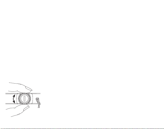
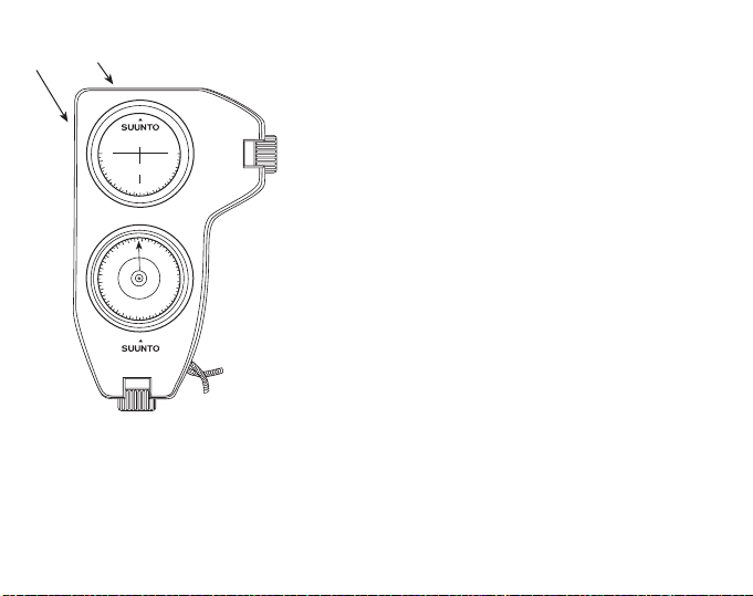
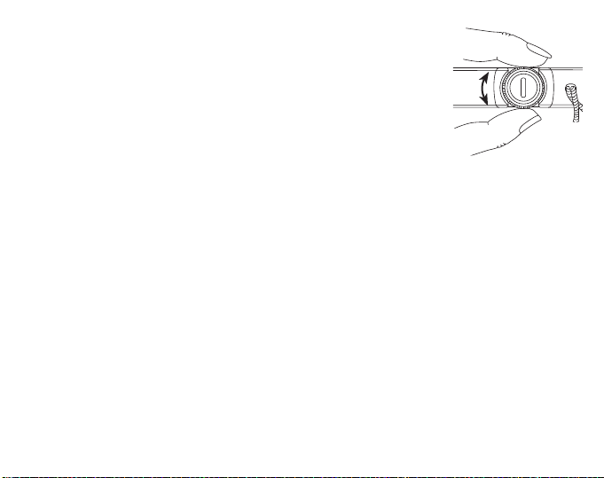
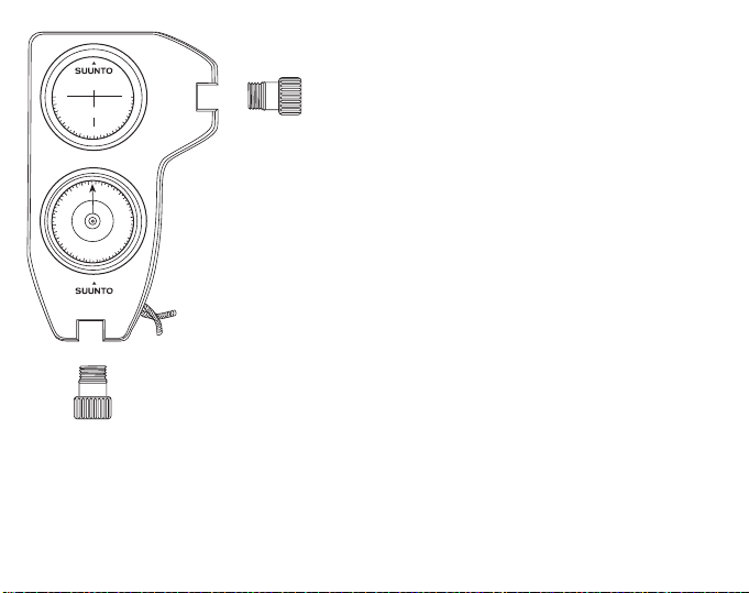
ADJUSTING OPTICS
The optics of the Tandem can be adjusted by turning the eye
piece with your fingers as shown in Figure 1. Adjust the eye
piece so that both the hairline and the scale are sharp and the
eye piece slot settles in a vertical position in the bearing
compass and in a horizontal position in the clinometer.
Fig. 1. Adjusting optics
4
Page 6
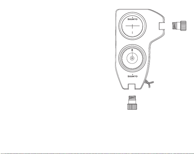
CLEANING THE TANDEM
0
90
90
Code:
PM-5/360PC
TANDEM
W
E
N
S
Fig. 2. Removing the eye piece
In the case humidity or dirt develop inside
the Tandem it can be cleaned by removing
the detachable eye piece. The eye piece can
be removed by rotating it counter-clockwise
(Fig. 2). Rinse with clean water, allow to dry
and carefully reassemble the eye piece.
Caution! Do not use detergents or solvents
of any kind as they might cause damage to
the capsules.
5
Page 7
TWO CONTACT
EDGES
0
90
90
Code:
PM-5/360PC
TANDEM
W
E
N
S
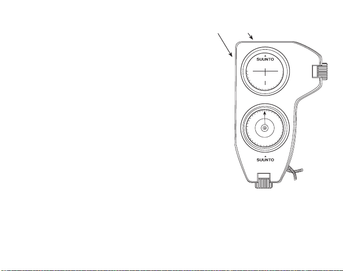
Fig. 3. Edges for contact
measurement
CONTACT MEASURING
The Tandem can be used for aligning satellite
dish antennas or for other type of contact measuring. The clinometer incorporates two different
contact edges (see Fig. 3) which enable the measurement to be made compared to the horizontal
or vertical plane. The scale (0 – 90 – 0 degrees)
can be used in contact measuring and it gives the
angle of the surface compared to the contact
plane.
6
Page 8

BEARING COMPASS
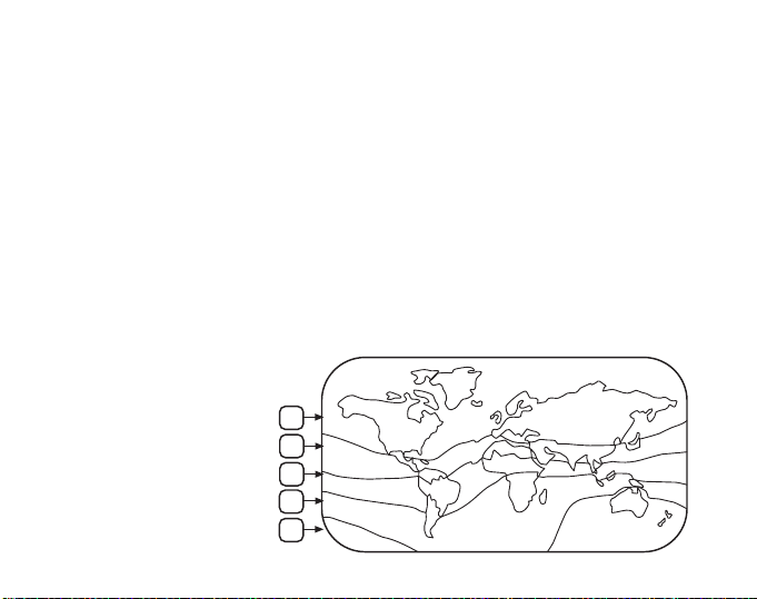
Fig. 4. The balancing
zones
Construction
The bearing compass is designed to combine extreme accuracy with ease and speed
of operation. The card is supported by a jewel bearing and it is immersed in a
dampening fluid, giving vibrationless, smooth movement. The compass has been
given permanent antistatic treatment.
Inclination - balancing
The compass card is balanced to correspond to area within which the compass is
used. When using the compass elsewhere (e.g. on trips abroad) the change of the
vertical magnetic field could make the compass card dip and this may cause
difficulties in taking the bearing. The balancing zone (see Fig. 4), if other than one, is
indicated on the back of the instrument below the serial number, contact your dealer
for details.
1
2
3
4
5
7
Page 9

Declination
The compass reads magnetic north, which differs from true north by the amount of
the local declination which is printed on your map. In order to lay out on a map a
bearing obtained with the compass, the plus or minus declination for the locality in
question must be added to or subtracted from the compass bearing.
Deviation
Iron and steel objects close to the compass, like a wristwatch or steel rimmed
eyeglasses, may cause deviation. Whenever possible, remove such objects to a safe
distance. Large structures like buildings, reinforced concrete quays etc. will cause
deviation at some distance. A reverse sighting from the opposite end of the target line
will show up any deviation present.
Operation
With both eyes open, aim the compass so that the hairline is superimposed on the
target, when viewed through the lens. The main scale (large numbers) gives the
bearing from your position to the target, the small numbers give a reverse bearing
from the target to your position. This feature is of great assistance when calculating a
precise position.
Use the left or the right eye as preferred. With both eyes open, an optical illusion
makes the hairline appear to continue above the instrument frame, superimposed on
the target. This improves reading accuracy and speed.
8
Page 10
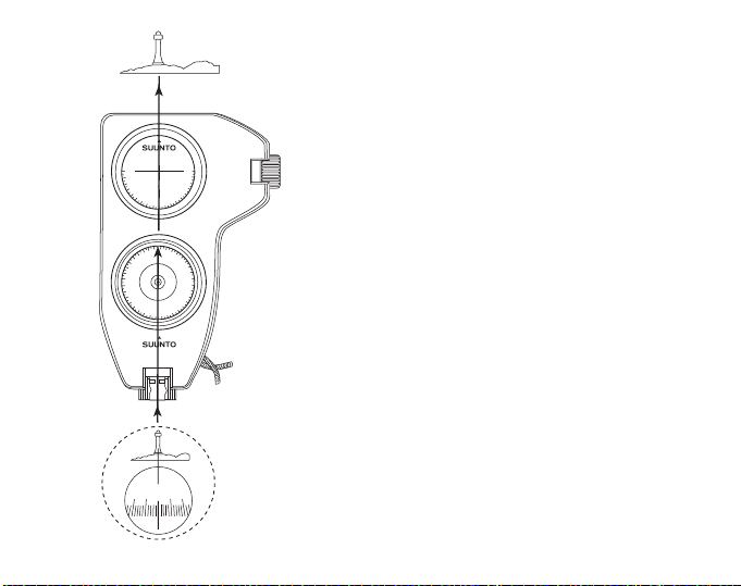
Because of an eye condition called heterophoria,
the reading accuracy of some users may be
impaired. Check for this as follows:
Take a reading with both eyes open and then close
the free eye. If the reading does not change
appreciably there is no disalignment of the eye
90
90
Code:
PM-5/360PC
0
axes, and both eyes can be kept open. Should there
be a difference in the readings, keep the other eye
closed and sight halfway above the instrument
body. The hairline now rises above the instrument
body and is seen against the target (Fig. 5).
N
E
W
S
TANDEM
View
190 180
10
180
350
0
Fig. 5. The hairline is seen against the target
9
Page 11
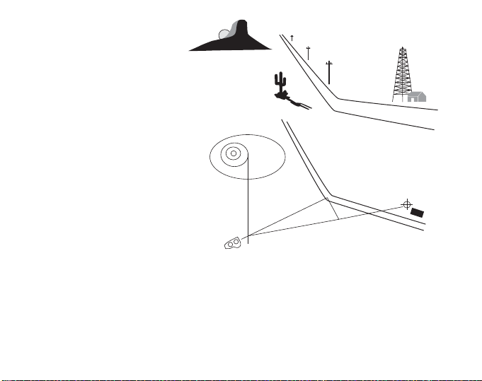
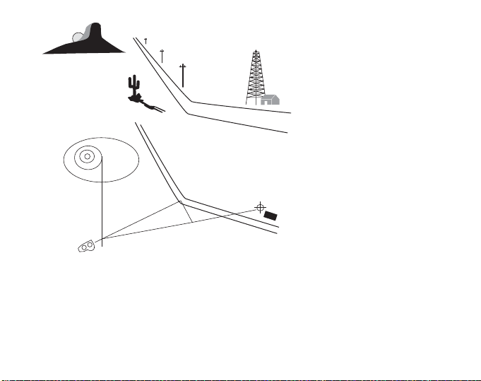
The instrument can also be
Fig. 6. Triangulation
used for triangulation, see Fig 6.
The bearings obtained from the
main scale are 0° against the hill
and 64° against the curve of the
road, or 180° and 244° on the
reverse scale. Y our own location
is indicated by the intersection
point of these two lines. When
performing very accurate positioning tasks the bearings
obtained have to be corrected
for local declination.
t
The co-tangent table at the back
of the Tandem can be utilized
for distance calculations, and
especially for locating position in
64
°
0
°
90
°
15
°
cases where two landmarks are
visible at a narrow angle. This
procedure is also illustrated in
Fig. 6.
The angle between the curve of the road and the oil derrick is 15°. A line is drawn at a
90° angle to the 64° bearing line from the curve of the road toward the oil derrick
bearing line. The distance, as measured on the chart, is 1.6 km [1 mile]. Then your
position is cot 15° x 1.6 km = 6 km [cot 15'° x 1 mile = 3.7 mile] along the corrected
bearing line of 64°.
10
Page 12

COPYRIGHT, TRADEMARK AND PATENT NOTICE
These instructions are copyrighted and all rights are reserved. It may not, in whole or
in part be copied, photocopied, reproduced, translated, or reduced to any media
without prior written consent from SUUNTO.
SUUNTO, Tandem and their logos are all registered trademarks of SUUNTO. All
rights are reserved. Patents have been issued or applied for one or several features
of this product.
ISO 9001
SUUNTO 0y's Quality Assurance System is certified by Det Norske Veritas to be
according to the ISO 9001 in all SUUNTO Oy's operations (Quality Certificate No. 96HEL- AQ-220).
CLINOMETER
Construction
The scale card is supported by a jewel bearing assembly and all moving parts are
immersed in a damping liquid inside a high strength hermetically sealed plastic
container. The liquid dampens all undue scale vibrations and permits a smooth
shockless movement of the scale card.
11
Page 13
Instructions for use
10
10
-
0
0
-
10
10
+
+
10
10
-
0
0
-
10
10
+
+
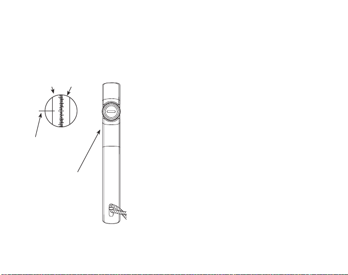
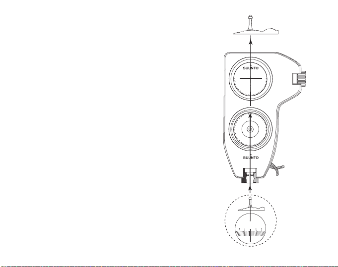
Fig. 7. The hairline
indicates the reading
Readings are usually taken with the right eye. Owing to differences in the keenness of
the sight of the eyes and because of personal preferences the use of the left eye is
sometimes easier. It is of prime importance that both eyes are kept open. The supporting hand must not obstruct the vision of the other eye.
+ AND -
DEGREE
SCALE
+ AND PER CENT
SCALE
The instrument is held in front of the reading eye so
that the scale can be read through the eye piece,
and the round side-window faces to the left.
The instrument is aimed at the object by raising or
lowering it until the horizontal hairline is sighted
against the point to be measured. The position of
the hairline now on the scale is the reading. Owing
to an optical illusion the hairline (cross-hair) seems
HAIRLINE
EXTENDED
BY OPTICAL
ILLUSION
THIRD SCALE
IN SIDE
WINDOW
to continue outside the housing and is thus easily
observed against the sighted object (Fig. 7).
The left-hand scale angle gives the slope angle in
degrees from the horizontal plane at eye level.
The right-hand scale gives the height of the point of
sight from the same horizontal eye level, and it is
expressed in per cent of the horizontal distance.
The following example illustrates the procedure.
12
Page 14
12 m
25 m [82 ft]
3.25 m
[10½ ft]
41%
10.25 m
[33½ ft]
13.5 m
[44½ ft]
13%
Fig. 8. Measuring height of a pillar
Fig. 9. Taking two readings
[38 ft]
1.6 m
[5½ ft]
25 m [82 ft]
48 %
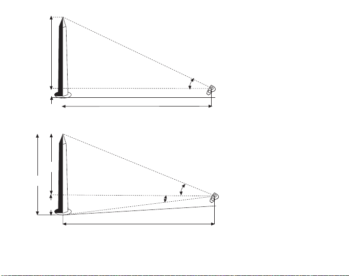
25 ½°
The task is to measure the
height of a pillar at a distance
of 25 m [82 ft] on level ground
(Fig. 8).
The instrument is tilted so that
the hairline is seen against the
pillar-top (apex). The reading
obtained will be 48 % (ca
25 ½°), As the distance is
25 m [82 ft] the height of the
pillar is 48 / 100 x 25 = ca.
12 m [48 / 100 x 82 ft = ca.
39 ft]. To this must be added
the eye's height from the
ground, e.g., 1.6 m [5 ½ ft].
Their sum is 13.6 m [44 ½ ft],
the height of the pillar.
In very exact measurements,
and particularly on sloping
ground two readings are
taken, one to the top, the other
to the base of the pillar. When
the pillar base is below eye
level the percentages obtained are added. The total
height is the sum percentage
13
Page 15
of the horizontal distance. For example (Fig. 9), if the apex reading is 41 % and the
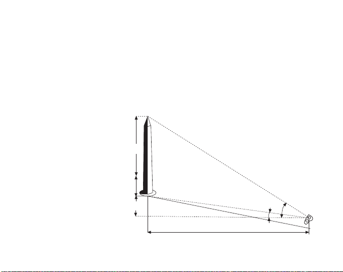
Fig. 10. Pillar above eye level
3.5 m
[11½ ft]
64%
12.5 m
[33½ ft]
14%
25 m
[82 ft]
ground reading 13 %, the total height of the pillar measured from a distance of 25 m
[82 ft] is (41 + 13) / 100 x 25 m = 54 / 100 x 25 m = ca. 13.5 m [(41 + 13)/100 x 82 ft =
54/100 x 82 ft = ca. 44 ½ ft].
When the pillar base is above eye level, the base reading is subtracted from the apex
reading, and the total height is the difference percentage of the horizontal distance.
For example (Fig. 10), if the apex reading is 64 % and the base reading 14 %, the
total height is (64 – 14) / 100 x 25 m = 50 / 100 x 25 m = 12.5 m [(64 – 14) / 100 x 82 ft
= 50 / 100 x 82 ft = 41 ft]. When calculations are made mentally, it is advisable to use
measuring distances of 50, 100 or 200 ft, for the sake of simplicity.
14
Page 16

All readings on the percentage scale are based on the horizontal distance. This
means that if the distance on sloping terrain is measured along the ground an error is
introduced, and this must be corrected for accurate results. The error is insignificant
for most purposes at small ground slope angles but increases progressively as the
angle increases.
The trigonometrical correlation is H = h x cos a
where
H = the true or corrected height,
h = the observed height and
a = the ground slope angle.
With the aid of the above equation the correction can also be made in the distance,
where
h = the distance measured along the ground
H = the horizontal distance sought. If the corrected distance is used no correction in
the height observed is needed.
15
Page 17

When calculating the hori-
1.6 m
[5½ ft]
29%
1.6 m
[5½ ft]
9%
25 m
[82 ft]
23%
24.7 m [81 ft]
Fig. 11. Calculating horizontal distance by using
ground distance and slope angle
23
100
-------- -
29
100
-------- -
52
100
-------- -
=+
zontal distance by using
the ground distance and
the slope angle, it must be
pointed out that an error is
introduced if the slope is
measured from eye level to
the pillar base. Measuring
the slope along the ground
would be cumbersome and
inconvenient. No error is
introduced, however, when
the slope angle is measured from eye level to a
sighting mark made or
placed on the pillar at eye level (Fig. 11) whereby the two lines of measurement
become parallel. The true angle of slope is 9 degrees. The example shown in Fig. 11
illustrates both methods of calculation.
Method 1. Measure the ground distance. This is found to be 25 m [82 ft]. Then
measure the slope angle. This is 9 degrees. Read percentages of top and ground
points. These are 29 and 23 per cent.
Calculate:
16
Page 18

Take 52 per cent of 25 m [82 ft]. This is 13 m [42.6 ft]. Multiply this by the cosine of
9 degrees.
0.987 x 13 m = 12.8 m [0.987 x 42.6 fl = 42 ft]
Method 2. Multiply the ground distance by the slope angle cosine (strait distance).
0.987 x 25 m = 24.7 m [0.987 x 82 ft = 80.9 ft]. Add percentage readings as above
and take the sum percentage of the corrected distance. 52 / 100 x 24.7 m = 12.8 m
[52 / 100 x 80.9 ft = 42 ft]. This example shows that a slope angle of 9 degre es
causes a correction of only 2.3 % but when the slope angle is 35 degrees the
correction means a reduction of about 18 % in the observed height.
Nomographic height correction
When the accompanying nomogram is used, all correction calculations become
unnecessary. Only a ruler or some other convenient object with a straight edge is
needed to obtain the nomographical solution. The nomogram is used by placing the
ruler so that its edge intersects the angle scale on the left at the slope angle point and
the observed height scale (on the right) at the pertinent point. The corrected height (or
distance) is read at the point where the edge intersects the corrected height scale in
the middle. When using a measuring distance of 20 m or 100 ft along the ground the
correction procedure becomes very simple. No slope angle measurement is then
necessary. One needs only the reading of the top point and that of the ground point.
Depending on the situation their sum or difference gives the apparent height directly
in feet. This is then corrected as follows:
17
Page 19

First, find on the right-hand scale in the
Uphill
Base reading
16
15
14
13
12
11
10
9
8
7
6
5
4
3
2
1
0
21
20
19
18
17
16
15
14
13
12
11
10
9
8
7
6
5
4
2
6
7
8
9
10
11
12
13
14
15
16
17
18
19
20
m
Apparent height
4
5
6
7
8
9
10
11
12
13
14
15
16
17
18
19
20
m
Corrected height
L-20
m
Downhill
Fig. 12.
nomogram the point indicating the
apparent height. Secondly find on the lefthand double scale the point indicating the
ground point reading. Thirdly, connect
these points. The corrected reading will
be found from the pertinent middle scale
at the point of intersection. In this
procedure the slope angle can be
neglected as the left-hand ground point
scale has been constructed so that both
the ground slope angle and the average
eye level height of 1.6 m [5.5 ft] have
been taken into account.
18
Page 20
Suunto Tandem
GUIDE DE L'UTILISATEUR
FR
Page 21

TABLE DES MATIÈRES
SUUNTO TANDEM, DEUX INSTRUMENTS DE PRECISION EN UN ..............4
REGLAGE DES OPTIQUES ..............................................................................5
NETTOYAGE DE TANDEM ...............................................................................6
MESURE DE CONTACT .................................................................................... 7
BOUSSOLE DE RELEVEMENT ........................................................................ 8
COPYRIGHT ET MARQUE DEPOSEE ........................................................... 12
IS0 9001 ........................................................................................................... 12
LE CLINOMETRE ............................................................................................12
3
Page 22

SUUNTO TANDEM, DEUX INSTRUMENTS DE PRECISION
EN UN
Félicitations pour votre choix. Le SUUNTO TANDEM est l'instrument idéal pour la
mesure des pentes, hauteurs et relèvements. C'est une boussole liquide de précision
combinés à un clinometre dans un boitier en aluminium. Très simple d'utilisation et
assez solide pour resister aux différents impacts, à la corrosion et à l'eau.
Ce instrument de qualité combine precision avec facilité, rapidité d'utilisation et
légèreté.
Par sa conception compacte, le SUUNTO TANDEM, est extrêmement pratique pour
toutes sortes de travaux. Grâce à son forme spéciale, sa tenue en main est très
agréable. Les oeilletons de visée peuvent être ajustés à votre vue pour rendre la
lecture plus aisée. L'échelle de pente du clinomètre est graduée en pourcentage et
en degrés (0 – 90°, 0 – 150 %). L'échelle des azimuts de la boussole est graduée en
degrés (0 – 360° et échelle inversée). Le clinomètre et la boussole ont une
graduation à 1° et 1 %, et sont calibrés individuellement. Les deux bords
perpendiculaires de l'appareil permettent de faire des mesures en positionnant
l'appareil directement sur un objet (par ex. en cas d'installation et positionnement
d'une antenne satellite).
4
Page 23
REGLAGE DES OPTIQUES
Les optiques de TANDEM peuvent être réglées en tournant
l'oculaire avec les doigts (fig. 1, voir revers). Régler l'oculaire
de façon à ce que la ligne de visée et l'échelle, soient nettes, et
que la fente de l'oculaire se mette dans une position verticale
dans le cas de la boussole de relèvement, et dans une position
horizontale, dans le cas du clinomètre.
Fig. 1 Réglage des optiques
5
Page 24
0
90
90
Code:
PM-5/360PC
TANDEM
W
E
N
S
Fig. 2. L'oculaire mobile se dévisse
en tournant
6
NETTOYAGE DE TANDEM
Dans le cas où il y aurait de l'humidité ou de
la saleté dans le TANDEM, il peut être
nettoyé en enlevant l'oculaire mobile. Il se
dévisse, en le tournant dans le sens inverse
des aiguilles d'une montre (fig. 2, voir
revers). Rincer à l'eau propre, laisser
sécher, et assembler attentivement.
Attention! Ne jamais utiliser de solvants
ou détergents, qui peuvent gravement
endommager la capsule.
Page 25
MESURE DE CONTACT
Fig. 3. Les côtés pour la mesure
de contact
Le TANDEM est un instrument idéal pour
l'orientation d'antenne satellite ou la mesure
directionnelle de toute autre surface de
contact. Le clinomètre comporte deux échelles
différentes permettant d'effectuer la mesure par
rapport à son plan horizontal ou vertical (fig. 3,
voir revers). L'échelle (0 – 90 – 0°) s'utilise pour
la mesure de contact; elle fournit l'angle de la
surface mesurée par rapport à la surface de
contact.
DEUX BORDS DE
CONTACT
90
Code:
PM-5/360PC
0
N
W
TANDEM
90
E
S
7
Page 26
BOUSSOLE DE RELEVEMENT
Fig. 4. Les zones
de balancement
Conception
La boussole de relèvement de précision est conçue de façon à combiner le maximum
de précision avec la légèreté et la rapidité. La rose des vents de la boussole est
immergée dans un liquide amortisseur qui donne un mouvement doux, exempt de
vibrations. La boussole a été soumise à un traitement antistatique permanent.
Equilibrage de l'inclinaison
La rose des vents est équilibrée de façon à ce qu'elle corresponde à la région
d'utilisation. Si vous utilisez votre TANDEM dans une des quatre autres zones de
balancement (proche orient, afrique équatoriale ... ) la variation du champs
magnétique peut faire pencher la rose des vents ce qui peut rendre la visée difficile
ou erronée. La zone de balancement (voir fig. 4) est indiquée au dos de l'instrument,
juste au dessous du numéro de série. Pour de plus amples renseignements,
contactez votre importateur SUUNTO.
1
2
3
4
5
8
Page 27

Déclinaison
La boussole indique le pôle nord magnétique, qui diffère du nord réel, comme la
déclinaison locale qui est imprimée sur votre carte. Pour pouvoir établir sur la carte
un relèvement obtenu avec la boussole, la déclinaison positive ou négative pour la
position en question doit être ajoutée au soustraite du relèvement de la boussole.
Déviation
Des objets de fer et d'acier se trouvant près de la boussole, comme par ex. une
montre bracelet, ou des lunettes à monture d'acier, peuvent causer des sérieuses
erreurs de lecture. De tels objets doivent être, autant que possible, placés à une
bonne distance. De grandes structures, tels que bâtiments, quais en béton armé,
etc., peuvent causer des erreurs de lecture à une certaine distance. Une direction
inverse à partir de l'extrémité opposée de la ligne d'objectif montre toute déviation
éxistante.
Mode d'emploi
Tenir les deux yeux ouverts et diriger la boussole de telle façon que la ligne de visée
soit dirigée vers l'objectif lorsque l'on regarde à travers la lentille. La graduation
principale (grands chiffres) donne le relèvement, à partir de votre position; les petits
chiffres donnent le relèvement inverse, c'est à dire, à partir de l'objectif vers votre
position. Cette propriété est d'une position exacte.
Employer soit l'oeil gauche, soit l'oeil droit, au choix. Si l'on a les deux yeux ouverts,
une illusion optique donne l'impression que la ligne de visée continue par dessus le
cadre de l'instrument en direction de l'objectif. Celà améliore l'exactitude et la rapidité
de la lecture.
9
Page 28
En raison d'une phénomène optique, appelé
0
90
90
Code:
PM-5/360PC
TANDEM
W
E
N
S
0
350
10
190 180
180
Vue
hétérophorie, il est possible que la précision de la
lecture soit altérée chez certains. Celà se contrôle
de la façon suivante:
Lire en ayant les deux yeux ouverts. Fermer
ensuite l'oeil libre. Si la lecture ne change pas
notablement, il n'y a pas de différence dans les
axes optiques et les deux yeux peuvent être tenus
ouverts. S'il apparaît une différence à la lecture :
fermer l'autre oeil et diriger le regard à mi-chemin
au dessus de l'instrument. La ligne de visée
s'élève maintenant au dessus de l'instrument et
est vue contre l'objectif (fig. 5).
10
Fig. 5. La ligne de visée vue
contre l'objectif
Page 29
L'instrument peut aussi être uti-
Fig. 6. La triangulation
lisé pour la triangulation, (voir fig
6). Les relèvements qui ont été
obtenus à l'aide de la graduation
principale sont 0° contre la colline et 64° contre le virage, ou
180° et 244° sur la graduation
inverse. Votre pro pre position
est indiquée par le point d'intersection de ces deux lignes.
Lorsque l'on exécute des
t
recherches de positions précises, les relèvements obtenus
doivent être corrigés relative-
90
64
°
0
°
°
15
°
ment à la déclinaison locale.
Le table des cotangentes qui se
trouve au dos de TANDEM, peut
être employée pour les calculs
de distances, spécialement pour
la localisation de position dans
les cas où, deux amers apparaissent dans un angle aigu. L'angle entre le virage et le dérrick est de 15°. Une ligne
est tracée à un angle de 90° jusqu'à ligne de relèvement á 64° à partir du virage vers
la ligne de relèvement du derrick. La distance qui est ainsi mesurée sur la carte est
de 1,6 km [1 mile]. Votre position est donc: cot. 15° x 1,6 km = 6 km [cot. 15° x 1 mile
= 3,7 miles] le long de la ligne de relèvement corrigée à 64°.
11
Page 30

COPYRIGHT ET MARQUE DEPOSEE
Ce manuel d'utilisation est déposé. Tous droits réservés. Toute représentation,
reproduction ou traduction, même partielle par quelque procédé que ce soit effectuée
sans le consentement écrit de Suunto est illicite.
Suunto, Tandem et leurs logos sont des marques déposées ou non de Suunto. Tous
droits réservés.
Brevets déposés uo en cours pour une ou plusieurs caractéristiques de ce produit.
IS0 9001
Le Systéme d'Assurance Qualité de Suunto est certifié conforme ISO 9001 pour
toutes les opérations de Suunto OY par Det Norske Veritas (Certificat Qualité n° 96HEL-AQ-220).
LE CLINOMETRE
Construction
Le disque gradué se déplace entre deux paliers à rubis. Les pièces mobiles sont
logées dans une capsule en plastique hermétiquement close remplie de liquide.
Le liquide amortit toutes les oscillations qui perturbent le disque gradué, et fait que la
graduation se déplace lentement et également.
12
Page 31

Mode d'emploi
+ ET – LA
GRADUATION
EN DEGRÉS
+ ET – LA
GRADUATION EN
POURCENTAGE
LE RÉTICULE
AGRANDI PAR
L’ILLUSION
OPTIQUE
LA TROISIÈME
GRADUATION À
L’ORIFICE
LATÉRAL
10
10
-
0
0
-
10
10
+
+
10
10
-
0
0
-
10
10
+
+
Fig. 7. Le réticule indique
le résultat de mesure
Dans la plupart des cas, les mesures se font avec l'oeil droit. Selon les propriétés des
yeux de l'usager, il peut cependant parfois être plus facile de se servir de l'oeil
gauche. Il est très important de garder les deux yeux ouverts. La main qui supporte le
clinomètre ne doit pas ombrager le champ de vision d'aucun des deux yeux.
Le clinomètre est tenu devant l'oeil de manière que
la graduation soit lisible à travers l'optique et que
l'orifice latéral rond soit à gauche. Le clinomètre est
dirigé vers l'objectif en le levant ou le baissant,
jusqu'à ce que le réticule horizontal rencontre
l'objectif à mesurer. La position du réticule sur la
graduation indique la mesure. En raison d'une
illusion optique, le réticule semble se prolonger audelà du boîtier du clinomètre et est de ce fait facile
à discerner en surimpression du point de visée
(fig.7).
La graduation à gauche, indique l'angle en degrés
du plan horizontal et de la droite allant de l'oeil à
l'objectif, et la graduation à droite indique la
hauteur de l'objectif en pourcentage, par rapport
au plan horizontal, la hauteur de l'oeil de
l'opérateur étant le plan zéro. Les exemples
suivants illustrent les différents modes de mesure.
13
Page 32

La mesure de la hauteur
Fig. 8. La mesure de la hauteur d'un pilier
Fig. 9. L'exécution de deux mesures
d'un pilier sur un plan égal à
une distance de 25 mètres
[82 ft] (fig. 8).
Incliner le clinomètre de
12 m
[38 ft]
façon que le réticule soit
visible contre le sommet du
pilier. La valeur lue sera
48 % (env. 25,5°). Aune
1.6 m
[5½ ft]
distance de 25 m, la hauteur
du pilier est 48 / 100 x 25 =
env. 12 m [48 / 100 x 82 ft =
env. 39 ft]. En y ajoutant la
hauteur de l opérateur (du
soi à l'oeil, soit env. 1,60 m –
5,5 ft) on obtient comme
résultat 13,6 m [44½ ft].
Dans les mesures très pré-
13.5 m
[44½ ft]
10.25 m
[33½ ft]
cises et particulièrement
dans un terrain inégal, on
éxécute deux mesures, l'une
3.25 m
[10½ ft]
vers le sommet et l'autre
vers la base du pilier. Si la
valeur vers le sommet du
pilier est par ex. 41 % et vers
la base 13 %, la hauteur
14
25 m [82 ft]
25 m [82 ft]
13%
41%
48 %
25 ½°
Page 33

totale du pilier, mesurée à une distance de 25 m sera (41 + 13) / 100 x 25 m = 54 /
Fig. 10. Le pilier au-dessus du niveau des yeux
3.5 m
[11½ ft]
64%
12.5 m
[33½ ft]
14%
25 m
[82 ft]
100 X 25 m = env. 13,5 m [(41 + 13) / 100 x 82 ft = 54 / 100 x 82 ft = env. 44½ft] (fig.
9).
Si le bas du pilier est au dessus du niveau des yeux, on soustraira la valeur obtenue
vers la base de celle vers le sommet. Par ex. (fig. 10) si la visée vers le sommet du
pilier donne la valeur 64 %, et celle vers le bas du pilier 14 %, la hauteur du pilier à
une distance de 25 m sera (64 – 14) / 100 x 25 m – 50 / 100 x 25 m = 12,5 m [(64 –
14) / l 00 x 82 ft = 50 / 100 x 82 ft = 41 ft]. Quand les calculs sont faits mentalement, il
est conseillé d'utiliser 50, 100 or 200 ft comme la distance de mesure pour rendre les
calculs plus simples.
15
Page 34

Toutes les valeurs de la graduation en pourcentage sont basées sur la distance dans
le plan horizontal. Dans un terrain incliné les valeurs mesurées doivent donc être
corrigées en conséquence. Si les dénivellations du terrain sont faibles, l'erreur reste
insignifiante, mais s'accroît progressivement, lorsque l'angle de déclivité s'agrandit.
La formule trigonométrique est
H = h x cos a
ou H = hauteur réelle (corrigée)
h = hauteur lue
a = angle de déclivité.
Cette formule permet également de corriger une erreur de distance, où
h = distance mesurée
H = distance horizontale
16
Page 35

1.6 m
[5½ ft]
29%
1.6 m
[5½ ft]
9%
25 m
[82 ft]
23%
24.7 m [81 ft]
Fig. 11. Le calcul d'une distance horizontale en utilisant
la distance le long du sol et l'angle de déclivité
En calculant une distance
dans le plan horizontal, à
partir d'une distance le
long du sol d'un angle de
déclivité, il y a lieu de tenir
compte de ce que l'angle
de déclivité doit être
mesuré du niveau de l'oeil
à l'objectif marqué sur le
surface du pilier, qui est au
niveau de l'oeil (fig. 11). Si
la déclivité est mesurée du
niveau de l'oeil à la base
du pilier, il se produit une
erreur. La mesure de
déclivité, le long du sol,
donne également un
résultat correct, mais la
mesure peut être difficile.
17
Page 36

Méthode 1. Mesurez la distance le long du sol. C'est 25m [82 ft]. Ensuite, mesurez
23
100
-------- -
29
100
-------- -
52
100
-------- -=+
l'angle de déclivité. C'est 9°. Lisez les pourcentages du point le plus haut et de la
base. Ce sont 29 % et 23 %.
Calculez:
Prenez 52 % de 25 m [82 ft]. C'est 13 m [42,6 ft]. Multipliez celà avec le cosinus du
9°. 0,987 x 13 m = 12,8 m [ 0,987 x 42,6 ft = 42 ft].
Méthode 2. Multipliez la distance le long du sol par le cosinus de l'angle de déclivité.
0,987 x 25 m = 24,7 m [0,987 x 82 ft = 80,9 ft].
Ajoutez les pourcentages lus comme au dessus, et prenez l'addition des
pourcentages de la distance corrigée. 52 / 100 x 24,7 m = 12,8 m [52 / 100 x 80,9 =
42 ft].
Cet exemple nous montre que l'angle de déclivité de 9° ne cause qu'une correction
de 2,3 %, mais, quand l'angle de déclivité est de 35°, la correction constitue une
réduction d'environ 18 % de la hauteur observée
18
Page 37

Emploi du nomogramme pour la correction de la hauteur
En utilisant le nomogramme livré avec le clinonnètre, tous les calculs de correction
sont inutiles. Il suffit d'avoir une règle ou un autre objet approprié à côtes droits.
Mettre la règle de manière que le bord de celle ci coupe la graduation d'angle
gauche, au droit de la valeur de hauteur mesurée. La valeur de hauteur (ou de
distance) corrigée s'obtient à l'endroit où la règle coupe la graduation médiane.
En utilisant une distance de mesure de 20 m [100 ft] et en mesurant cette distance le
long du sol, l'opération de correction est très simple. Il suffit d'avoir le relevé du point
le plus haut, et de la base; leur somme ou différence, selon la situation, donne alors
la hauteur apparente, qui est corrigée comme suit:
19
Page 38

16
15
14
13
12
11
10
9
8
7
6
5
4
3
2
1
0
21
20
19
18
17
16
15
14
13
12
11
10
9
8
7
6
5
4
2
6
7
8
9
10
11
12
13
14
15
16
17
18
19
20
m
4
5
6
7
8
9
10
11
12
13
14
15
16
17
18
19
20
m
L-20
m
Terrain mountant
Lecture à la base
Hauteur corrigeé
Hauteur apparente
Terrain déclinant
Fig. 12.
20
Cherchez d'abord sur la graduation de
droite du nomogramme la hauteur
apparente mesurée. Cherchez ensuite
sur la graduation double de gauche, le
point correspondant à la valeur
obtenue à la base du pilier. Réunir ces
points, la valeur corrigée sera alors le
point d'intersection de la graduation
médiane. En ce cas, on peut ignorer
l'angle de déclivité, car la graduation de
gauche a été établie en tenant compte
de l'angle de déclivité du sol et du
niveau moyen de l'oeil 1,6 m [5,5 ft].
Page 39

Suunto Tandem
BEDIENUNGSANLEITUNG
DE
Page 40

INHALTSVERZEICHNIS
SUUNTO TANDEM, ZWEI PRÄZISIONSGERÄTE IN EINEM ..........................4
EINSTELLUNG DER OPTIK ..............................................................................5
REINIGUNG DES TANDEM ..............................................................................6
ANSCHLAGMESSUNGEN ................................................................................ 7
PEILKOMPASS ..................................................................................................8
COPYRIGHT, WARENZEICHEN UND PATENTE ..........................................12
ISO 9001 .......................................................................................................... 12
INKLINOMETER .............................................................................................. 13
3
Page 41

SUUNTO TANDEM, ZWEI PRÄZISIONSGERÄTE IN EINEM
Wir gratulieren Ihnen zu Ihrer Entscheidung für den Suunto Tandem. Der Suunto
Tandem ist das einzige Gerät, das Sie für Höhen- und Neigungsmessungen sowie
Kompasspeilungen benötigen. Es handelt sich um einen flüssigkeitsgefüllten
Präzisionskompass und Inklinometer in einem kompakten Aluminiumgehäuse.
Das Gerät ist benutzerfreundlich und robust sowie unempfindlich gegen Stöße,
Korrosion und Wasser. Dieses hochwertige Präzisionsinstrument vereint Messgenauigkeit mit schneller und bequemer Einhandbedienung.
Dank der kompakten Konstruktion eignet sich der Suunto Tandem ideal für die
meisten Einsatzarten. Durch die ergonomische Form liegt er bequem in der Hand.
Die Optik des Tandem-Geräts kann angepasst werden, um das Ablesen zu
erleichtern. Die Skala des Inklinometers ist in Grad und Prozent geeicht (0 bis 90°,
0 bis 150 %), die Kompassskala in Azimut (0 bis 360° mit Umkehrskala). Sowohl
de Kompass als auch der Inklinometer sind in 1° / 1 %-Schritten markiert und einzeln
kalibriert. Die beiden Schenkel des Winkels von 90° erlauben auch Anschlagmessungen, beispielsweise bei der Positionierung und dem Aufbau einer Satellitenantenne.
4
Page 42

EINSTELLUNG DER OPTIK
Die Optik des Tandem-Geräts lässt sich durch Verdrehen
des Okulars mit den Fingern wie in Abbildung 1 einstellen.
Das Okular so einstellen, dass sowohl das Fadenkreuz als
auch die Skala scharf zu erkennen sind, und der Schlitz
des Okulars in einer vertikalen Position im Peilkompass und
in einer horizontalen Position im Inklinometer einrastet.
Abb. 1. Einstellung der Optik
5
Page 43

0
90
90
Code:
PM-5/360PC
TANDEM
W
E
N
S
Abb. 2. Abnehmen des Okulars
6
REINIGUNG DES TANDEM
Wenn Feuchtigkeit oder Schmutz in
das Gerät gelangt sind, können diese
durch Abnehmen des Okulars entfernt
werden. Das Okular lässt sich durch Drehen entgegen dem Uhrzeigersinn entfernen (Abbildung 2). Mit sauberem
Wasser spülen, trocknen lassen und das
Okular vorsichtig wieder aufsetzen.
Achtung! Keine Lösungsmittel oder
Reinigungsmittel verwenden, da diese
die Instrumentenkapseln beschädigen
könnten.
Page 44

ANSCHLAGMESSUNGEN
Abb. 3. Kanten für Anschlagmessung
Der Suunto Tandem lässt sich beim Ausrichten
von Satellitenantennen und für andere Anschlagmessungen einsetzen. Der Inklinometer hat zwei
verschiedene Anschlagseiten (siehe Abbildung
3), so dass die Messung mit der horizontalen
oder vertikalen Ebene verglichen werden kann.
Die Skala von 0–90–0° kann für Anschlagmessungen verwendet werden und zeigt dann
den Winkel der Oberfläche im Vergleich mit
der Anschlagebene an.
ZWEI
ANSCHLAGKANTEN
90
Code:
PM-5/360PC
0
N
E
W
S
TANDEM
90
7
Page 45

PEILKOMPASS
Abb. 4. Die Inklinationskorrektur
Aufbau
Der Peilkompass zeichnet sich durch extreme Genauigkeit sowie schnelle und einfache Bedienung aus. Die Kompassnadel liegt auf einem Edelsteinlager und in einer
Dämpfungsflüssigkeit, so dass sich eine schwingungsfreie, sanfte Bewegung ergibt.
Der Kompass wurde so behandelt, dass er dauerhaft antistatisch ist.
Neigungsmessung – Korrektur der Inklination
Die Kompassscheibe ist so abgestimmt, dass sie dem Einsatzgebiet angepasst ist.
Wird der Kompass in einer anderen Region eingesetzt, beispielsweise bei Reisen im
Ausland, können die Änderungen des vertikalen Magnetfelds dazu führen, dass
die Kompassnadel „kippt“ und dadurch die Bestimmung der Peilung erschwert wird.
Gilt die Inklinationskorrektur (siehe Abbildung 4) für mehrere Regionen, sind
die betreffenden Regionen auf der Rückseite des Geräts unter der Seriennummer
angegeben, genaueres erfahren Sie von Ihrem Fachhändler.
1
2
3
4
5
8
Page 46

Deklination
Der Kompass zeigt die Lage des magnetischen Nordpols an, die vom geographischen Nordpol um den Betrag der lokalen Deklination abweicht, die auf Ihrer
Karte aufgedruckt ist. Um eine mit dem Kompass bestimmte Peilung in der Karte einzunorden, muss die positive oder negative Missweisung für die betreffende Region
von der Kompasspeilung subtrahiert oder dazu addiert werden.
Deviation
Eisen- und Stahlgegenstände in der Nähe des Kompasses, beispielsweise eine
Armbanduhr oder eine Brille mit Stahlgestell, können zu Abweichungen
der Magnetnadel führen. Sofern möglich, solche Gegenstände immer in sicherer
Entfernung halten. Große Bauten wie Gebäude, Anleger aus Stahlbeton usw.
verursachen auch in einiger Entfernung noch Abweichungen. Wird die Ziellinie von
der Gegenseite aus anvisiert, zeigt sich, ob eine Abweichung vorhanden ist.
Bedienung
Beide Augen öffnen und den Kompass so ausrichten, dass das Fadenkreuz über
dem Ziel liegt, das durch das Okular anvisiert wird. Die Hauptskala (große Zahlen)
zeigt die Peilung von der Position zum Ziel an, die kleinen Zahlen
die entgegengesetzte Peilung vom Ziel bis zu Ihrer Position. Diese Funktion ist zur
Berechnung einer exakten Position sehr hilfreich.
Je nach Bedarf das linke oder rechte Auge zum Anvisieren verwenden. Wenn beide
Augen geöffnet sind, erscheint durch eine optische Illusion das Fadenkreuz weiterhin
über dem Geräterahmen und wird durch das Ziel überlagert. Dadurch lassen sich
Ablesegenauigkeit und -geschwindigkeit erhöhen.
9
Page 47

Aufgrund einer als Heterophorie bezeichneten Fehlsichtigkeit kann die Ablesegenauigkeit bei manchen
Benutzern eingeschränkt sein. Ob Sie an einer
Heterophorie leiden, lässt sich wie folgt feststellen:
Messen Sie einen Punkt mit beiden geöffneten
Augen und schließen Sie dann ein Auge. Wenn sich
der Messwert nicht wesentlich ändert, existiert keine
Abweichung der Augensichtachsen, und Sie können
beide Augen geöffnet lassen. Sollten sich andere
Messwerte ergeben, lassen Sie das andere Auge
geschlossen, und sehen Sie nur mit einem Auge
über das Gerät. Das Fadenkreuz liegt jetzt über dem
Gerätegehäuse und vor dem anvisierten Ziel (siehe
Abbildung 5).
90
90
Code:
PM-5/360PC
0
N
E
W
S
TANDEM
Blick
190 180
10
180
350
0
Abb. 5. Das Fadenkreuz liegt vor
dem anvisierten Ziel
10
Page 48

t
Abb. 6. Triangulation
0
Das Instrument kann auch für
die Triangulation entsprechend Abbildung 6 verwendet
werden. Die Peilungen
der Hauptskala betragen 0° in
Richtung des Hügels und 64°
zur Straßenkurve bzw. 180°
und 244° auf der Umkehrskala. Die eigene Position
wird durch den Schnittpunkt
dieser beiden Linien bestimmt.
Bei sehr exakten Positionsbestimmungen müssen die ermittelten Peilungen unter Be-
90
64
°
°
°
15
°
rücksichtigung der lokalen
Deklination korrigiert werden.
Die Kotangenstabelle auf der
Rückseite des Tandem lässt
sich für Entfernungsberechnungen einsetzen, insbesondere für Positionen, bei
denen zwei Landmarken in
einem spitzen Winkel sichtbar
sind. Dieses Verfahren wird
auch in Abbildung 6 dargestellt.
11
Page 49

Der Winkel zwischen der Straßenkurve und dem Ölbohrturm beträgt 15°. Ziehen Sie
eine Linie im Winkel von 90° zu der 64°-Peillinie der Straßenkurve zur Peillinie
des Ölbohrturms. Die auf der Karte gemessene Entfernung beträgt 1,6 km (1 Meile).
Ihre Position ist dann cot 15° × 1,6 km = 6 km (cot 15° x 1 Meile = 3,7 Meilen) auf
de korrigierten Peillinie von 64°.
COPYRIGHT, WARENZEICHEN UND PATENTE
Diese Anweisungen unterliegen dem Copyright, alle Rechte vorbehalten. Sie dürfen
ohne die vorherige schriftliche Zustimmung von SUUNTO weder ganz noch teilweise
kopiert, fotokopiert, reproduziert, übersetzt oder für die Medien überarbeitet werden.
SUUNTO, Tandem und die entsprechenden Logos sind eingetragene Warenzeichen
von SUUNTO. Alle Rechte vorbehalten. Für mindestens eine Funktion
dieses Produkts wurden Patente erteilt oder angemeldet.
ISO 9001
Das Qualitätssicherungssystem der SUUNTO Oy erhielt durch Det Norske Veritas
das ISO 9001-Zertifikat, welches besagt, dass SUUNTO Oy in allen Arbeitsabläufen
diese Norm erfüllt (Qualitätszertifikat No. 96-HEL-AQ-220).
12
Page 50

INKLINOMETER
Aufbau
Die Kompassnadel ist in einem Edelsteinlager gelagert, alle beweglichen Teile
befinden sich in einer Dämpfungsflüssigkeit im Inneren eines hochfesten hermetisch
versiegelten Kunststoffgehäuses. Die Flüssigkeit dämpft alle übermäßigen
Schwingungen der Kompassnadel und erlaubt eine sanfte, zitterfreie Bewegung.
Bedienungsanleitung
Messungen erfolgen in der Regel mit dem rechten Auge. Aufgrund der unterschiedlichen Sehschärfe der Augen und von persönlichen Präferenzen ist ein
Ablesen mit dem linken Auge mitunter einfacher. Es sollten beide Augen offen
gehalten werden. Die haltende Hand darf die Sicht des anderen Auges nicht
behindern.
13
Page 51

+ UND –
GRADSKALA
+ UND –
PROZENTSKALA
DAS
FADENKREUZ
ERSCHEINT
AUFGRUND
OPTISCHER
DRITTE
SKALA IM
INNERN DES
FENSTERS
10
10
-
0
0
-
10
10
+
+
10
10
-
0
0
-
10
10
+
+
Abb. 7. Das Fadenkreuz
zeigt den Messwert an
14
Das Instrument vor das ablesende Auge halten, so
dass die Skala durch das Okular abgelesen
werden kann und das runde Seitenfenster nach
links zeigt. Mit dem Instrument das Ziel anvisieren
und dabei das Instrument so lange höher oder
tiefer stellen, bis die horizontale Linie des Fadenkreuzes vor dem zu vermessenden Punkt erkennbar ist. Die Position des Fadenkreuzes auf
der Skala ist der Messwert. Aufgrund einer optischen Täuschung erscheint das Fadenkreuz weiterhin außerhalb des Gehäuses und ist daher vor dem
anvisierten Ziel sichtbar (Abbildung 7).
Der Winkel auf der linken Skala gibt den Neigungswinkel in Grad von der horizontalen Ebene in
Augenhöhe an. Die rechte Skala zeigt die Höhe
des Sichtpunkts von der gleichen horizontalen
Ebene in Augenhöhe an und wird in Prozent
der horizontalen Entfernung angegeben. Das folgende Beispiel zeigt die Vorgehensweise.
Page 52

12 m
Abb. 8. Messung der Höhe einer Säule
Abb. 9. Zwei Messungen vornehmen
[38 ft]
1.6 m
[5½ ft]
25 m [82 ft]
10.25 m
[33½ ft]
13.5 m
[44½ ft]
3.25 m
[10½ ft]
25 m [82 ft]
13%
41%
48 %
25 ½°
Es soll die Höhe einer Säule
in einer Entfernung von 25 m
(82 Fuß) in ebenem Gelände
(Abbildung 8) gemessen
werden.
Das Instrument wird so gekippt, dass das Fadenkreuz
auf die Spitze der Säule
zeigt (Scheitelpunkt). Es ergibt sich ein Messwert von
48 % (ca. 25,5°). Da der Abstand 25 m (82 ft) beträgt, ist
die Höhe der Säule 48 : 100
× 25 = ca. 12 m (48 / 100 x
82 ft = ca. 39 ft). Dazu muss
die Höhe addiert werden, in
der sich das Instrument vor
dem Auge befindet, z. B.
1,6m (5,5 ft). DieSumme ist
somit 13,6 m (44,5 ft), dies
ist die Höhe der Säule.
15
Page 53

Bei sehr exakten Messun-
Abb. 10. Säule über Augenhöhe
gen und insbesondere in abschüssigem Gelände werden zwei Messungen vorgenommen, eine für die Spitze
12.5 m
[33½ ft]
und eine für den Fuß der
Säule. Wenn der Säulenfuß
sich unterhalb der Augenhöhe befindet, werden
die ermittelten Prozentwerte
addiert. Die Gesamthöhe ist
die Summe der Prozentwerte der horizontalen Ent-
3.5 m
[11½ ft]
25 m
64%
14%
[82 ft]
fernung. Wird für die Spitze
beispielsweise wie in Abbildung 9 ein Wert von 41 %
ermittelt und für die Messung am Fuß 13 %, ergibt sich als Gesamthöhe der Säule
bei einem Abstand von 25 m (82 ft) ein Wert von ca.: (41 + 13) / 100 x 25 m = 54 / 100
x 25 m = ca. 13,5 m [(41 + 13) / 100 x 82 ft = 54 / 100 x 82 ft = ca. 44,5 ft].
Befindet sich der Säulenfuß oberhalb der Augenhöhe, wird die Messung für
den Säulenfuß von der Messung für die Säulenspitze subtrahiert, und die
Gesamthöhe entspricht dem Differenzbetrag der Prozentsätze für die horizontale
Entfernung. Beträgt beispielsweise die Messung für die Säulenspitze wie in
Abbildung 10 64 % und der Messwert für den Säulenfuß 14 %, ergibt sich eine
Gesamthöhe von: (64 – 14) / 100 x 25 m = 50 / 100 x 25 m = 12,5 m [(64 – 14) / 100
x 82 fit = 50 / 100 x 82 ft = 41 ft]. Sollen die Berechnungen im Kopf durchgeführt
16
Page 54

werden, ist es aus Gründen der Einfachheit sinnvoll, Entfernungen von 50, 100 oder
200 m zu wählen.
Alle Messwerte auf der Prozentskala beziehen sich auf die horizontale Entfernung.
Das heißt, bei Messung von Abständen in abschüssigem Gelände ergibt sich bei
Messungen am Boden ein Messfehler, der korrigiert werden muss, um exakte
Ergebnisse zu erhalten. Dieser Fehler ist für die meisten Fälle bei geringer Neigung
des Geländes insignifikant, erhöht sich jedoch progressiv mit zunehmender Neigung
des Geländes.
Die trigonometrische Korrektur erfolgt mit H = h × cos a.
Hierbei ist:
H = echte oder korrigierte Höhe,
h = gemessene Höhe und
a = der Winkel, mit dem das Gelände abfällt.
Mit der oben erwähnten Korrekturgleichung kann auch die gemessene Entfernung
korrigiert werden. Hierbei ist
h = die gemessene Entfernung am Boden und
H die gewünschte horizontale Entfernung. Wird die korrigierte Entfernung verwendet,
muss die gemessene Höhe nicht korrigiert werden.
17
Page 55

Bei der Berechnung der
1.6 m
[5½ ft]
29%
1.6 m
[5½ ft]
9%
25 m
[82 ft]
23%
24.7 m [81 ft]
Abb. 11. Berechnung der horizontalen Entfernung aus
dem Abstand am Boden und dem Neigungswinkel des
Geländes
horizontalen Entfernung aus dem Abstand
am Boden und dem
Neigungswinkel des
Geländes sei darauf
hingewiesen, dass ein
Messfehler vorhanden
ist, wenn die Neigung
von der Augenhöhe bis
zum Säulenfuß gemessen wird. Die Messung
der Neigung direkt am
Boden wäre mühsam
und unbequem. Es entsteht jedoch kein Messfehler, wenn der Neigungswinkel aus Augenhöhe für eine
Markierung bestimmt wird, die an der Säule in Augenhöhe angebracht oder
vorhanden ist (siehe Abbildung 11). Dadurch verlaufen die beiden Messlinien p arallel.
Der tatsächliche Neigungswinkel des Geländes beträgt 9°. Das Beispiel in Abbildung
11 zeigt die beiden Berechnungsmethoden.
Methode 1: Den Abstand am Boden messen. Dieser beträgt 25 m. Den Neigungswinkel messen. Dieser beträgt 9°. Die Prozentangaben für den oberen und unteren
Messpunkt ermitteln. Diese betragen 29 und 23 %.
18
Page 56

Berechnung:
23
100
-------- -
29
100
-------- -
52
100
-------- -=+
52 % von 25 m Dies entspricht 13 m. Multiplikation mit dem Kosinus von 9°
0,987 x 13 m = 12,8 m [0,987 x 42,6 fl = 42 ft]
Methode 2: Multiplikation der Entfernung am Boden mit dem Kosinus
des Neigungswinkels (direkte Entfernung) 0,987 x 25 m = 24,7 m [0,987 x 82 ft: =
80,9 ft]. Addition der Prozentwerte wie oben und Ermittlung des Gesamtprozentwerts
für die korrigierte Entfernung 52 / 100 x 24,7 m = 12,8 m [52 / 100 x 80,9 ft: = 42 ft].
Dieses Beispiel zeigt, dass ein Neigungswinkel von 9° nur eine Korrektur von 2,3 %
erfordert. Beträgt der Neigungswinkel des Geländes jedoch 35°, ist eine Korrektur
der gemessenen Höhe von etwa 18 % erforderlich.
Höhenkorrektur mit dem Nomogramm
Wird das mitgelieferte Nomogramm verwendet, werden alle Korrekturberechnungen
überflüssig. Um die tatsächlichen Werte zu ermitteln, ist für das Nomogramm lediglich
ein Lineal oder ein anderer Gegenstand mit gerader Kante erforderlich. Das Lineal so
auf das Nomogramm auflegen, dass es den Punkt auf der Winkelskala links,
der der Geländeneigung entspricht und den gemessenen Punkt auf der Höhenskala
verbindet. Die korrigierte Höhe oder Entfernung wird an dem Punkt abgelesen, wo
das Lineal in der Mitte die Skala mit der korrigierten Höhe schneidet. Bei einer
Messentfernung von 20 m am Boden wird die Korrekturprozedur extrem einfach. In
19
Page 57

diesem Fall ist keine Messung
16
15
14
13
12
11
10
9
8
7
6
5
4
3
2
1
0
21
20
19
18
17
16
15
14
13
12
11
10
9
8
7
6
5
4
2
6
7
8
9
10
11
12
13
14
15
16
17
18
19
20
m
4
5
6
7
8
9
10
11
12
13
14
15
16
17
18
19
20
m
L-20
m
Ansteigendes
Gelände
Ablesung beim Anvisieren
d. unteren Stammende
Scheinbare Höhe
Wahre Höhe
Fallendes Gelände
Fig. 12.
de Geländeneigung erforderlich.
Es müssen lediglich die Messwerte an
der Spitze und am Fuß des anvisierten
Gegenstands bekannt sein. Je nach
de Situation gibt die Summe bzw.
die Differenz die annähernde Höhe
direkt an. Dieser Wert wird dann wie
folgt korrigiert:
Zunächst auf der rechten Skala
des Nomogramms den Punkt für
die annähernde Höhe suchen. Dann auf
der linken Skala des Nomogramms
den Punkt für die Messung am Boden
suchen. Diese beiden Punkte verbinden.
Der korrigierte Messwert befindet sich
am Schnittpunkt der Verbindungslinie
mit der mittleren Skala. Bei dieser
Vorgehensweise kann der Neigungswinkel vernachlässigt werden, weil
die Messskala für die Bodenmessungen
auf der linken Seite so gestaltet wurde,
dass bereits der Neigungswinkel des
Geländes und die durchschnittliche
Augenhöhe von 1,6 m berücksichtigt
sind.
20
Page 58

Suunto Tandem
GUÍA DEL USUARIO
ES
Page 59

ÍNDICE
SUUNTO TANDEM, DOS INSTRUMENTOS DE PRECISIÓN EN UNO ........... 4
AJUSTE DE LOS ELEMENTOS ÓPTICOS .......................................................5
LIMPIEZA DEL TANDEM ................................................................................... 6
MEDICIÓN POR CONTACTO ...........................................................................7
BRÚJULA ........................................................................................................... 8
AVISO DE COPYRIGHT, MARCA REGISTRADA Y PATENTE ...................... 13
ISO 9001 .......................................................................................................... 13
INCLINÓMETRO .............................................................................................. 14
3
Page 60

SUUNTO TANDEM, DOS INSTRUMENTOS DE PRECISIÓN
EN UNO
Enhorabuena por elegir el Suunto Tandem. Este Suunto Tandem es todo lo que
necesitará para mediciones de pendiente y altura y orientación con brújula. Se trata
de una brújula de precisión rellena de líquido y un inclinómetro dentro una misma
carcasa compacta de aluminio, muy fácil de usar y protegido contra impactos,
corrosión y salpicaduras. Este instrumento de precisión y alta calidad combina una
alta exactitud con un manejo rápido y sencillo, con una sola mano.
Su diseño de bolsillo hace que el Suunto Tandem sea idóneo para todo tipo de
trabajos. Su forma única permite sostenerlo cómodamente en la mano.
Los elementos ópticos del Tandem pueden ajustarse para facilitar la lectura.
La escala del inclinómetro se indica en grados y en porcentaje (de 0 a 90°, del 0 % al
150 %), mientras que la escala de la brújula es de acimut (de 0 a 360° con escala
inversa). Tanto el inclinómetro como la brújula están graduados con incrementos de
1° / 1% y cada uno se calibra de forma individual. Las dos superficies en ángulo recto
hacen posible hacer mediciones por contacto, por ejemplo al instalar y posicionar
una antena de satélite.
4
Page 61

AJUSTE DE LOS ELEMENTOS ÓPTICOS
Los elementos ópticos del Tandem pueden ajustarse
girando el ocular con los dedos como se muestra en la
Figura 1. Ajuste el ocular de forma que tanto el retículo
como la escala se vean nítidamente y la ranura del ocular
quede situada en posición vertical en la brújula y en
posición horizontal en el inclinómetro.
Fig. 1. Ajuste de los elementos ópticos
5
Page 62

90
Fig. 2. Cómo retirar el ocular
90
Code:
PM-5/360PC
0
N
E
W
S
TANDEM
6
LIMPIEZA DEL TANDEM
En caso de que se acumule humedad o
suciedad dentro del Tandem, puede limpiarlo
tras retirar el ocular desmontable. Para retirar
el ocular, gírelo en el sentido contrario a las
agujas del reloj (Figura 2). Lávelo con agua
limpia, espere a que se seque y vuelva a
montar con cuidado el ocular.
¡Cuidado! No utilice detergentes ni
disolventes de ningún tipo, dado que pueden
causar daños a las cápsulas.
Page 63

MEDICIÓN POR CONTACTO
Fig. 3. Superficies para
medición por contacto
El Tandem puede usarse para alinear antenas
parabólicas de satélite o para otros tipos de
mediciones por contacto. El inclinómetro incorpora dos superficies de contacto diferentes
(consulte la Figura 3) que permiten realizar las
mediciones respecto del plano horizontal o
vertical. La escala (0 – 90 – 0 grados) puede
usarse para mediciones por contacto e indica
el ángulo de la superficie respecto del plano
de contacto.
DOS SUPERFICIES
DE CONTACTO
90
Code:
PM-5/360PC
0
N
W
S
TANDEM
90
E
7
Page 64

BRÚJULA
2
1
4
3
5
Fig. 4. Zonas de
equilibrado
Diseño
La brújula se ha diseñado para combinar una excepcional exactitud con un manejo
sencillo y rápido. La escala se apoya en un rodamiento de piedra preciosa y está
sumergido en un líquido amortiguador, lo que le proporciona un movimiento suave y
sin vibraciones. La brújula ha sido sometida a un tratamiento antiestático
permanente.
Inclinación y equilibrado
La escala de la brújula está equilibrada para la zona en la que se prevé utilizar la
brújula. Si utiliza la brújula en otras zonas (por ejemplo en viajes al extranjero),
la variación del campo magnético vertical podría hacer que la escala de la brújula se
incline y podría ser más difícil medir la orientación. La zona para la que está
equilibrado el instrumento (consulte la Figura 4) se indica en la parte trasera del
8
Page 65

instrumento, debajo del número de serie, póngase en contacto con su distribuidor
para obtener más detalles.
Declinación
La brújula indica el norte magnético, que difiere del norte real en la magnitud de
la declinación local, que aparece impresa en su mapa. Para poder trazar en un mapa
la orientación obtenida con la brújula, la declinación positiva o negativa de la
localidad correspondiente debe sumarse o restarse de la orientación indicada por
la brújula.
Desviación
Los objetos de hierro y acero situados cerca de la brújula, como un reloj de muñeca o
unas gafas con montura de acero, pueden provocar desviaciones. Siempre que sea
posible, sitúe estos objetos a una distancia segura. Las estructuras de gran tamaño,
como edificios, muelles de hormigón armado, etc. pueden causar desviaciones a
cierta distancia. Una observación inversa desde el lado opuesto de la línea de
objetivo le permitirá determinar si existe cualquier desviación.
9
Page 66

Manejo
Sin cerrar ningún ojo, oriente la brújula de forma que el retículo quede situado sobre
el objetivo, visto a través del visor. La escala principal (números de mayor tamaño)
indica la orientación desde su posición hacia el objetivo. Los números pequeños
indican la orientación inversa desde el objetivo hasta su posición. Esta característica
la resultará muy útil a la hora de calcular una posición exacta.
Utilice el ojo izquierdo o el derecho, según sus preferencias. Con los dos ojos
abiertos, una ilusión óptica hace que el retículo parezca continuar por encima del
bastidor del instrumento, superpuesto sobre el objetivo. De esta forma disfrutará de
más exactitud y agilidad en el trabajo.
10
Page 67

Debido a una afección ocular conocida como
0
90
90
Code:
PM-5/360PC
TANDEM
W
E
N
S
0
350
10
190 180
180
Vista
heteroforia, la exactitud de lectura de algunos
usuarios puede verse perjudicada. Para comprobar
si es su caso, haga lo siguiente:
Tome una lectura con los dos ojos abiertos y cierre
a continuación el ojo libre. Si la lectura no cambia
apreciablemente, quiere decir que no existen
problemas de alineación de los ejes del ojo y puede
mantener los dos ojos abiertos. Si detecta una
diferencia en las lecturas, mantenga el otro ojo
cerrado y mire a media altura por encima del cuerpo
del instrumento. Ahora el retículo se eleva por
encima del cuerpo del instrumento y se ve
superpuesta al objetivo (Figura 5).
Fig. 5. Retículo visto
sobre el objetivo
11
Page 68

Este instrumento también
Fig. 6. Triangulación
puede usarse para triangulaciones. Consulte la Figura
6. Las orientaciones obtenidas con la escala principal
se encuentran a 0° respecto
de la colina y a 64° respecto
de la curva de la carretera, o
a 180° y 244° en la escala
inversa. Su propia ubicación
se indica con el punto de
intersección de estas dos
líneas. A la hora de realizar
t
tareas de posicionamiento
de alta precisión, las orientaciones obtenidas deben
ser corregidas a la decli-
64
°
0
°
90
°
15
°
nación local.
La tabla de cotangentes de
la parte trasera del Tandem
puede usarse en los cálculos
de distancia y especialmente
a la hora de ubicar posiciones en los casos en que hay dos hitos visibles en un
ángulo reducido. Este procedimiento también se ilustra en la Figura 6.
El ángulo formado por la curva de la carretera y la torre de perforación e s de 15°.
Se traza una línea en ángulo recto respecto de la línea de orientación de 64°, desde
12
Page 69

la curva de la carretera hasta la línea de orientación de la torre de perforación.
La distancia medida en la tabla es de 1,6 km [1 milla]. Por tanto, su posición es cot
15° x 1,6 km = 6 km [cot 15'° x 1 milla = 3,7 millas] a lo largo de la línea de orientación
corregida de 64°.
AVISO DE COPYRIGHT, MARCA REGISTRADA Y PATENTE
Estas instrucciones están sujetas a copyright y se reservan todos los derechos.
No puede ser copiadas, fotocopiadas, reproducidas, traducidas ni transferidas a
ningún tipo de soporte sin la autorización previa por escrito de SUUNTO.
SUUNTO, Tandem y sus logotipos son marcas registradas de SUUNTO. Reservados
todos los derechos. Una o varias características de este producto tienen una patente
vigente o en proceso.
ISO 9001
El sistema de garantía de calidad de SUUNTO OY ha sido certificado por Det Norske
Veritas en cuanto a su cumplimiento con la norma ISO 9001 en todas las
instalaciones de SUUNTO Oy (certificado de calidad nº 96-HEL-AQ-220).
13
Page 70

INCLINÓMETRO
Diseño
La escala se apoya en un conjunto de rodamiento de piedra preciosa y todas las
partes móviles están sumergidas en un líquido amortiguador, dentro de un
contenedor de plástico sellado herméticamente y de alta resistencia. El líquido
amortigua todas las vibraciones no deseadas en la escala y permite que ésta se
mueva con suavidad y sin sacudidas.
Instrucciones de uso
Las lecturas se suelen tomar con el ojo derecho. Debido a las diferencias existentes
en la agudeza visual de cada ojo y en función de sus preferencias personales,
en ocasiones resulta más fácil usar el ojo izquierdo. Es de una importancia capital
mantener los dos ojos abiertos. La mano con la que sujete el instrumento no debe
obstaculizar la visión del otro ojo.
14
Page 71

El instrumento se sostiene delante del ojo con el que
ESCALA EN
GRADOS
+ Y –
ESCALA EN
PORCENTAJE
+ Y –
RETÍCULO
AMPLIADO
POR ILUSIÓN
ÓPTICA
TERCERA
ESCALA EN
VENTANA
LATERAL
10
10
-
0
0
-
10
10
+
+
10
10
-
0
0
-
10
10
+
+
Fig. 7. El retículo indica
la lectura
se realiza la medición, de forma que sea posible leer
la escala a través del ocular y la ventana lateral
redonda quede orientada hacia la izquierda. Para
apuntar el instrumento hacia el objeto, eleve o baje el
instrumento hasta que el retículo horizontal se vea
superpuesto sobre el punto a medir. Ahora, la
posición del retículo en la escala es la lectura.
Debido a una ilusión óptica, el retículo (la cruz de
hilos) parece continuar más allá de la carcasa y por
tanto puede observarse fácilmente superpuesto
sobre el objeto enfocado (Figura 7).
El ángulo de la escala izquierda indica el ángulo de
pendiente en grados, respecto del plano horizontal a
la altura de los ojos. La escala derecha indica la
altura del punto visualizado respecto de la misma
horizontal a la altura de los ojos y se expresa en
porcentaje de la distancia horizontal. En el ejemplo
siguiente se ilustra este procedimiento.
La tarea consiste en medir la altura de una columna
a una distancia de 25 m [82 pies] desde el nivel del
suelo (Figura 8).
15
Page 72

Se inclina el instrumento de
Fig. 8. Medición de la altura de una columna
forma que el retículo se vea
superpuesto sobre la parte
superior (la cúspide) de la
columna. La lectura obtenida
12 m
[38 ft]
será del 48 % (aprox. 25 ½°).
Dado que la distancia es de
25 m [82 pies], la altura de la
columna es de 48 / 100 x 25
= aprox. 12 metros [48 / 100
1.6 m
[5½ ft]
x 82 pies = aprox. 39 pies].
A ello debe sumarse la altura
de los ojos respecto del
terreno, es decir, 1,6 m [5 ½
pies]. La suma es 13,6 m
[44 ½ pies], la altura de la
columna.
16
25 m [82 ft]
48 %
25 ½°
Page 73

En mediciones muy exactas,
Fig. 9. Realización de dos lecturas
y especialmente en terrenos
inclinados, se toman dos
medidas, una hasta el
extremo superior de la
columna y otra hasta su
base. Si la base del pilar se
encuentra por debajo de la
altura de los ojos, se
obtienen y suman los por-
13.5 m
[44½ ft]
10.25 m
[33½ ft]
3.25 m
[10½ ft]
41%
13%
25 m [82 ft]
centajes. La altura total es la
suma de porcentajes de la
distancia horizontal.
Por ejemplo (Figura 9), si la lectura de la cúspide es del 41 % y la lectura en el
terreno es del 13 %, la altura total de la columna medida desde una distancia de 25 m
[82 pies] es (41 + 13) / 100 x 25 m = 54 / 100 x 25 m = aprox. 13,5 m [(41 + 13) / 100
x 82 pies = 54 / 100 x 82 pies = aprox. 44 ½ pies].
17
Page 74

Si la base de la columna se
Fig. 10. Columna por encima del nivel de los ojos
encuentra por encima del
nivel de los ojos, la lectura
de la base se resta de la
lectura de la cúspide y la
12.5 m
[33½ ft]
altura total es la diferencia
de porcentajes de la
distancia horizontal. Por
ejemplo (Figura 10), si la
lectura de cúspide es del 64
% y la lectura de la base es
del 14 %, la altura total es
de (64 – 14) / 100 x 25 m =
3.5 m
[11½ ft]
25 m
64%
14%
[82 ft]
50 / 100 x 25 m = 12,5 m
[(64 – 14) / 100 x 82 pies =
50 / 100 x 82 pies = 41
pies]. Si hace los cálculos mentalmente, es recomendable tomar las mediciones a
distancias de 50, 100 ó 200 pies para que resulte más sencillo.
Todas las lecturas de la escala de porcentajes se basan en la distancia horizontal.
Esto significa que si se mide la distancia en un terreno inclinado a lo largo del
terreno, se introduce un error que es necesario corregir para conseguir resultados
exactos. El error no es significativo para la mayoría de los fines si el terreno presenta
una inclinación reducida, pero aumenta progresivamente con el aumento de la
inclinación.
18
Page 75

La correlación trigonométrica es H = h x cos a
Donde
H = La altura real o corregida
h = La altura observada
a = El ángulo de inclinación del terreno
Con la ayuda de la ecuación anterior, la corrección también puede hacerse en la
distancia, donde
h = La distancia medida a lo largo del terreno
H = La distancia horizontal buscada Si se usa la distancia corregida, no se requiere
ninguna corrección en la altura observada.
Al calcular la distancia horizontal a partir de la distancia sobre el terreno y el ángulo
de inclinación, es necesario tener en cuenta que se introduce un error si la pendiente
se mide desde la altura de los ojos hasta la base de la columna. La medición de la
inclinación a lo largo del terreno sería trabajosa e incómoda. Sin embargo, no se
introduce ningún error si el ángulo de inclinación se mide desde la altura de los ojos
hasta una marca de observación realizada o situada en al superficie del pilar a la
altura de los ojos (Figura 11), dado que las dos líneas de medición quedan paralelas.
El ángulo de inclinación real es de 9 grados. El ejemplo mostrado en la Figura 11
ilustra los dos métodos de cálculo.
19
Page 76

1.6 m
Fig. 11. Cálculo de la distancia horizontal con la dist ancia
sobre el terreno y el ángulo de inclinación
23
100
-------- -
29
100
-------- -
52
100
-------- -=+
[5½ ft]
24.7 m [81 ft]
25 m
23%
29%
9%
[82 ft]
Método 1. Mida la distancia a nivel del terreno. Se determina que es de 25 m [82
pies]. A continuación, mida el ángulo de inclinación. Es de 9 grados. Lea los
porcentajes del punto superior y del terreno. Se trata del 29 % y el 23 %.
Calcule:
Obtenga el 52 % de 25 m [82 pies]. Es 13 m [42,6 pies]. Multiplique este valor por el
20
1.6 m
[5½ ft]
Page 77

coseno de 9 grados.
0,987 x 13 m = 12,8 m [0,987 x 42,6 pies = 42 pies]
Método 2. Multiplique la distancia sobre el terreno por el coseno del ángulo de
inclinación (distancia recta). 0,987 x 25 m = 24,7 m [0,987 x 82 pies = 80,9 pies].
Sume los porcentajes leídos de la forma indicada arriba y calcule la distancia
corregida con la suma de los porcentajes. 52 / 100 x 24,7 m = 12,8 m [52 / 100 x 80,9
pies = 42 pies]. En este ejemplo se muestra que un ángulo de inclinación de 9 grados
causa una corrección de sólo un 2,3 %, pero si el ángulo de inclinación es de 35
grados, la corrección supone la reducción de la altura observada en
aproximadamente un 18 %.
Corrección de la altura con el nomograma
Si se utiliza el nomograma que se incluye, se elimina la necesidad de realizar
cálculos de corrección. Sólo se requiere una regla u otro objeto fácil de usar con un
borde recto, para obtener la solución nomográfica. Para usar el nomograma, coloque
la regla de forma que su borde corte la escala de ángulos de la izquierda en el punto
que corresponda al ángulo de inclinación y la escala de altura observada (a la
derecha) en el punto pertinente. La altura (o distancia) corregida se lee en el punto
en el que el borde corta la escala de altura de la parte central. Si se utiliza una
distancia de medición de 20 m ó 100 pies sobre el terreno, el procedimiento de
corrección es muy sencillo. En este caso no se requiere ninguna medición del ángulo
de inclinación. Sólo es necesario hacer la lectura del punto superior y la del punto a
la altura del terreno. En función de la situación, su suma o resta indica la altura
21
Page 78

aparente, directamente en pies. A
16
15
14
13
12
11
10
9
8
7
6
5
4
3
2
1
0
21
20
19
18
17
16
15
14
13
12
11
10
9
8
7
6
5
4
2
6
7
8
9
10
11
12
13
14
15
16
17
18
19
20
m
4
5
6
7
8
9
10
11
12
13
14
15
16
17
18
19
20
m
L-20
m
Lectura desde la base
Altura corregida
Altura aparente
Pendiente
descendente
Pendiente
ascendente
Fig. 12.
continuación, este valor se corrige de la
forma siguiente:
En primer lugar, busque en la escala
derecha del nomograma el punto
correspondiente a la altura aparente. En
segundo lugar, busque en la escala
doble de la izquierda el punto que indica
la lectura del punto situado a la altura del
terreno. En tercer lugar, conecte estos
puntos. La lectura corregida se indica en
la escala central pertinente, en el punto
de intersección. En este procedimiento,
el ángulo de inclinación puede omitirse,
dado que la escala de puntos izquierda
para el terreno se ha creado de forma
que se tengan en cuenta tanto el ángulo
de inclinación del terreno como la altura
media de los ojos 1,6 m [5,5 pies].
22
Page 79

Suunto Tandem
GUIDA DELL'UTENTE
IT
Page 80

INDICE
SUUNTO TANDEM, DUE STRUMENTI DI PRECISIONE IN UNO ...................4
REGOLAZIONE DELL'OTTICA .......................................................................... 4
PULIZIA DI TANDEM .........................................................................................5
MISURAZIONE A CONTATTO .......................................................................... 6
BUSSOLA DA RILEVAMENTO .......................................................................... 7
COPYRIGHT, MARCHIO DI FABBRICA E BREVETTO .................................. 11
ISO 9001 .......................................................................................................... 11
CLINOMETRO ................................................................................................. 11
3
Page 81

SUUNTO TANDEM, DUE STRUMENTI DI PRECISIONE IN UNO
Congratulazioni per il vostro acquisto di Suunto Tandem. Suunto Tandem è la
risposta per le misurazioni sia d'inclinazione che d'altezza e per i rilevamenti con
bussola. È sia bussola di precisione riempita di liquido che clinometro, tutto all'interno
di un alloggiamento compatto in alluminio, facile da utilizzare e sufficientemente
robusto da resistere a urti, corrosione e acqua. Questo strumento di precisione di alta
qualità combina l'accuratezza di precisione a un uso facile e rapido che può avvenire
anche solo con una mano.
La struttura di dimensioni ridotte rende il Tandem Suunto la soluzione ideale per ogni
tipo di lavoro. La sua forma unica lo rende pratico da sorreggere. L'ottica di Tandem
può essere regolata per facilitare la lettura. La scala del clinometro è in gradi e in
percentuale (0 – 90°, 0 – 150 %) mentre la scala della bussola è in azimut (0 –
360°con scala inversa). Sia il clinometro che la bussola sono graduati con incrementi
di 1° / 1 % e ciascuno strumento è calibrato individualmente. I due bordi ad angolo
retto rendono possibili le misurazioni a contatto, ad esempio per l'installazione e il
posizionamento di un'antenna satellitare.
REGOLAZIONE DELL'OTTICA
L'ottica di Tandem può essere regolata girando l'oculare con le
dita, come da Figura 1. Regolare l'oculare in modo che sia la
linea di puntamento che la scala siano ben visibili e che
l'apertura dell'oculare si inserisca in posizione verticale nella
bussola per i rilevamenti e in posizione orizzontale nel
clinometro.
4
Fig. 1. Regolazione dell'ottica
Page 82

PULIZIA DI TANDEM
0
90
90
Code:
PM-5/360PC
TANDEM
W
E
N
S
Fig. 2. Rimozione dell' oculare
Qualora si accumuli sporco o umidità
all'interno di Tandem, è possibile pulirlo
staccando l'oculare rimovibile. L' oculare può
essere rimosso ruotandolo in senso antiorario
(Fig. 2). Risciacquare con acqua pulita, fare
asciugare e riassemblare con attenzione
l'oculare.
Attenzione! Non utilizzare detergenti o
solventi di alcun tipo, poiché potrebbero
danneggiare le capsule.
5
Page 83

MISURAZIONE A CONTATTO
Fig. 3. Bordi
per la misurazione a contatto
Il Tandem può essere utilizzato per l'allineamento
delle antenne paraboliche o per altri tipi di
misurazione a contatto. Il clinometro possiede
due bordi di contatto differenti (vedere Fig. 3),
che consentono di confrontare la misurazione
con il piano orizzontale o verticale. La scala (0 –
90 – 0 gradi) può essere utilizzata nelle
misurazioni a contatto e indica l'angolo della
superficie rispetto al piano di contatto.
6
Page 84

BUSSOLA DA RILEVAMENTO
Fig. 4. Le zone
d'equilibrio
Struttura
La bussola da rilevamento è progettata per unire un'estrema precisione a un
funzionamento facile e veloce. La scheda è sostenuta da un gruppo di supporto in
pietra dura ed è immersa in un liquido di smorzamento per consentire un movimento
fluido e privo di vibrazioni. Alla bussola viene applicato un trattamento permanente
antistatico.
Inclinazione - equilibrio
La scheda della scala è bilanciata per corrispondere all'area al cui interno viene
utilizzata la bussola. Durante l'utilizzo della bussola in altri luoghi (es.: nei viaggi
all'estero) il cambio del campo magnetico verticale potrebbe inclinare la scheda,
causando difficoltà durante il rilevamento. La zona d'equilibrio (vedere Fig. 4), se
diversa, è indicata sul retro dello strumento sotto il numero di serie; contattare il
proprio fornitore di fiducia per dettagli.
1
2
3
4
5
7
Page 85

Declinazione
La bussola legge il nord magnetico, che è diverso dal nord geografico per la quantità
di declinazione locale stampata sulla mappa. Per applicare su una mappa un
rilevamento ottenuto con la bussola, la declinazione positiva o negativa per la località
in questione deve essere aggiunta o sottratta dal rilevamento della bussola.
Deviazione
Gli oggetti di ferro e acciaio posti vicino alla bussola, ad esempio orologi od occhiali
da vista con montatura in acciaio, potrebbero causare deviazioni. Ove possibile,
spostare tali oggetti a una distanza di sicurezza. Strutture grandi quali edifici e
banchine in cemento armato causano deviazione a una certa distanza. Per rilevare la
possibile deviazione, eseguire un avvistamento contrario dalla parte opposta della
linea dell'obiettivo.
Funzionamento
Tenere entrambi gli occhi ben aperti e puntare la bussola in modo che la linea di
puntamento sia sovrapposta all'obiettivo, guardandolo attraverso le lenti. La scala
principale (numeri grandi) fornisce il rilevamento dalla propria posizione verso
l'obiettivo, i numeri piccoli indicano un rilevamento inverso dall'obiettivo verso la
propria posizione. Tale caratteristica si rivela assai utile durante il calcolo di una
posizione precisa.
Utilizzare l'occhio sinistro o destro, a seconda della propria preferenza. Quando
entrambi gli occhi sono aperti, un'illusione ottica fa proseguire la linea di puntamento
al di là del corpo dello strumento, sovrapponendola all'obiettivo. Ciò consente di
incrementare la precisione e la velocità.
8
Page 86

A causa di un disturbo della vista detto eteroforia, la
precisione con cui alcuni utenti rilevano i dati della
lettura potrebbe essere ridotta. Per controllare la
presenza di tale problema, effettuare la seguente
procedura:
eseguire una lettura tenendo entrambi gli occhi
aperti, quindi chiudere quello libero. Se la lettura
non cambia notevolmente, gli assi visivi sono
allineati ed è possibile tenere entrambi gli occhi
aperti. Se dovesse verificarsi una differenza nelle
letture, tenere l'altro occhio chiuso e fissare a
mezza altezza sopra lo strumento. La linea di
puntamento apparirà al di sopra del corpo dello
strumento e sarà visibile sull'obiettivo (Fig. 5).
Fig. 5. La linea di puntamento appare sull'obiettivo
9
Page 87

Lo strumento può essere
Fig. 6. Triangolazione
utilizzato anche per la
triangolazione, vedere Fig. 6. I
rilevamenti ottenuti dalla scala
principale sono 0° rispetto alla
collina e 64° rispetto alla curva
della strada, oppure 180° e 244°
nella scala inversa. La propria
posizione è indicata dal punto di
intersezione di queste due linee.
Durante l'esecuzione di
operazioni di posizionamento
assai precise, i rilevamenti
t
ottenuti devono essere corretti
per la declinazione locale.
La tabella trigonometrica posta
nel retro del T andem può essere
64
°
0
°
90
°
15
°
utilizzata per il calcolo di
distanze e soprattutto per
determinare posizioni quando
due punti di riferimento
appaiono in un angolo molto
ristretto. Tale procedura è illustrata nella Fig. 6.
L'angolo tra la curva della strada e la torre per il petrolio (derrick) è 15°. Viene
tracciata una linea a un angolo di 90° verso la linea di rilevazione di 64°, che parte
dalla curva della strada e arriva alla linea di rilevazione del derrick. La distanza, come
10
Page 88

misurata nella tabella, è 1,6 km [1 miglio]. Quindi, la propria posizione è cot
15° x 1 ,6 km = 6 km [cot 15'° x 1 miglio = 3,7 miglia] lungo la linea di rilevazione
corretta di 64°.
COPYRIGHT, MARCHIO DI FABBRICA E BREVETTO
Le presenti istruzioni sono coperte da copyright. Tutti i diritti sono riservati. Ne è
vietata la riproduzione, la traduzione o la riproduzione sia totale che parziale, con
qualsiasi mezzo o tecnica, senza il previo consenso scritto da parte di SUUNTO.
SUUNTO, Tandem e relativi loghi sono tutti marchi commerciali registrati di proprietà
di SUUNTO. Tutti i diritti sono riservati. Sono stati rilasciati o applicati dei brevetti per
una o più caratteristiche del presente prodotto.
ISO 9001
Il Sistema di Controllo Qualità di SUUNTO 0y è certificato dal Det Norske Veritas
quale conforme all’ISO 9001 in tutte le sue operazioni (Certificato di Qualità n° 96HEL-AQ-220).
CLINOMETRO
Struttura
La scheda della scala è sostenuta da un gruppo di supporto in pietra dura e tutte le
parti mobili sono immerse in un liquido di smorzamento all'interno di un resistente
contenitore di plastica sigillato ermeticamente. Il liquido smorza tutte le vibrazioni di
scala eccessive e consente un movimento fluido privo di scosse della scheda della
scala.
11
Page 89

Istruzioni per l'uso
10
10
-
0
0
-
10
10
+
+
Fig. 7. La linea di puntamento
indica la lettura
Le letture vengono solitamente eseguite con l'occhio destro. A causa delle differenze
nell'acutezza visiva e delle preferenze personali, a volte è più facile utilizzare l'occhio
sinistro. È di importanza fondamentale che entrambi gli occhi siano ben aperti. La
mano di sostegno non deve ostruire la visibilità dell'altro occhio.
Lo strumento viene posto di fronte all'occhio di
lettura, in modo da leggere la scala attraverso
l'oculare, mentre la finestra circolare è rivolta a
sinistra. Lo strumento viene puntato verso l'oggetto
sollevandolo o abbassandolo, finché la linea di
puntamento orizzontale non viene visualizzata sul
punto da misurare. La posizione della linea di
puntamento sulla scala corrisponde alla lettura. A
causa di un'illusione ottica, la linea di puntamento
(reticolo) sembra proseguire all'esterno
dell'alloggiamento e pertanto può essere osservata
sul terreno o sull'oggetto avvistato (Fig. 7).
L'angolo della scala di sinistra indica l'angolo di
inclinazione in gradi dal piano orizzontale
all'altezza degli occhi. La scala di destra indica
l'altezza del punto di avvistamento rispetto
all'altezza orizzontale degli occhi ed è espressa
nella percentuale della distanza orizzontale.
Il seguente esempio ne illustra la procedura.
12
Page 90

12 m
25 m [82 ft]
3.25 m
[10½ ft]
41%
10.25 m
[33½ ft]
13.5 m
[44½ ft]
13%
Fig. 8. Misurazione dell'altezza di un pilastro
Fig. 9. Esecuzione di due letture
[38 ft]
1.6 m
[5½ ft]
25 m [82 ft]
48 %
25 ½°
L'obiettivo è di misurare l'altezza
di un pilastro da una distanza di
25 m [82 piedi] a livello del suolo
(Fig. 8).
Lo strumento è inclinato in modo
da visualizzare la linea di
puntamento sulla cima del
pilastro (apice). La lettura
ottenuta sarà del 48 %, (circa il
25 ½°), dato che la distanza è di
25 m [82 piedi], l'altezza del
pilastro è 48 / 100 x 25 m = circa
12 m [48 / 100 x 82 piedi = circa
39 piedi]. A tale cifra deve
essere sommata l'altezza
dell'occhio dal terreno, ad es.
1,6 m [5 ½ piedi]. La somma è
quindi 13,6 m [44 ½ piedi],
ovvero l'altezza del pilastro.
Per misurazioni estremamente
precise, soprattutto su terreni in
pendenza, è necessario
effettuare due letture: una dalla
cima e l'altra dalla base del
pilastro. Quando la base del
pilastro è posta al di sotto
13
Page 91

dell'altezza degli occhi, le percentuali ottenute vengono sommate. L'altezza totale è
Fig. 10. Pilastro al di sopra dell'altezza degli occhi
3.5 m
[11½ ft]
64%
12.5 m
[33½ ft]
14%
25 m
[82 ft]
la somma percentuale della distanza orizzontale. Ad esempio (Fig. 9), se la lettura
dell'apice è 41 % e la lettura al terreno è 13 %, l'altezza totale del pilastro misurata da
una distanza di 25 m [41 piedi] è di (41+13) / 100 x 25 m = 54 / 100 x 25 m = circa
13,5 m [(41 + 13) / 100 x 82 piedi = 54 / 100 x 82 piedi = circa 44 ½ piedi].
Quando il pilastro si trova al di sopra dell'altezza degli occhi, la lettura della base
viene sottratta dalla lettura dell'apice e l'altezza totale equivale alla differenza
percentuale della distanza orizzontale. Ad esempio (Fig. 10), se la lettura dell'apice è
64 % e la lettura al terreno è 14 %, l' altezza totale del pilastro è di (64 – 14) / 100 x
25 m = 50 / 100 x 25 m = 12,5 m [(64 – 14) / 100 x 82 piedi = 50 / 100 x 82 piedi = 41
piedi]. Quando i calcoli vengono eseguiti mentalmente, si consiglia di utilizzare delle
distanze di misurazione di 50, 100 o 200 piedi, per pura semplicità.
14
Page 92

Tutte le letture della scala percentuale sono basate sulla distanza orizzontale. Ciò
significa che se la distanza sul terreno in pendenza viene misurata lungo il terreno si
verificherà un errore, che deve essere corretto per ottenere dei risultati precisi. Nella
maggioranza dei casi l'errore risulta insignificante per gli angoli di inclinazione del
terreno di dimensione ridotte, ma aumenta progressivamente con l'incremento
dell'angolo.
La correlazione trigonometrica è H = h x cos a
dove
H = l'altezza vera o corretta,
h = l'altezza osservata e
a = l'angolo di inclinazione del terreno.
Utilizzando tale equazione è possibile correggere anche la distanza, dove
h = la distanza misurata lungo il terreno
H = la distanza orizzontale avvistata. Se viene utilizzata la distanza giusta non è
necessario correggere l'altezza osservata.
Durante il calcolo della distanza orizzontale utilizzando la distanza del terreno e
l'inclinazione, si verificherà un errore, se l'inclinazione viene misurata dall'altezza
degli occhi alla base del pilastro. La misurazione dell'inclinazione sul terreno
potrebbe risultare scomoda. Per evitare errori, misurare l'angolo di inclinazione
dall'altezza degli occhi fino al punto di avvistamento eseguito o posizionato sul
15
Page 93

pilastro all'altezza degli occhi (Fig. 11), in tal modo le due linee di misurazione
1.6 m
[5½ ft]
29%
1.6 m
[5½ ft]
9%
25 m
[82 ft]
23%
24.7 m [81 ft]
Fig. 11. Calcolo della dist anza orizzontale utilizzando la
distanza del terreno e l'angolo di inclinazione
diventano parallele. Il vero angolo dell'inclinazione è di 9 gradi. L'esempio mostrato
nella Figura 11 illustra entrambi i metodi di calcolo.
Metodo 1. Misurazione della distanza del terreno. Essa corrisponde a 25 m [82 piedi].
Quindi misurare l'angolo di inclinazione. L'angolo è di 9 gradi. Leggere le percentuali
dei punti della cima e del terreno. Sono 20 e 23 percento.
Calcolo:
Prendere il 52 percento di 25 m [82 piedi]. Il risultato è 13 m [42,6 piedi]. Moltiplicarlo
per il coseno di 9 gradi.
0,987 x 13 m = 12,8 m [0,987 x 42,6 piedi = 42 piedi]
16
Page 94

Metodo 2. Moltiplicazione della distanza del terreno per il coseno dell'angolo di
23
100
-------- -
29
100
-------- -
52
100
-------- -=+
inclinazione (distanza rettilinea). 0,987 x 25 m = 24,7 m [0,987 x 82 piedi = 80,9 piedi]
Come nella procedura precedente, aggiungere le letture in percentuale e prendere la
somma percentuale della distanza corretta. 52 / 100 x 24,7 m = 12,8 m [52 / 100 x
80,9 piedi = 42 piedi]. Questo esempio mostra che un angolo di inclinazione di 9 gradi
causa una correzione di solo il 2,3 % ma quando l'angolo di inclinazione è di 35 gradi,
la correzione comporta una riduzione di circa il 18 % nell'altezza osservata.
Correzione nomografica dell'altezza
Utilizzando il nomogramma fornito, tutte le correzioni dei calcoli si rivelano inutili. Per
ottenere la soluzione nomografica, è necessario solo un righello o un altro oggetto
dotato di un bordo rettilineo. Per utilizzare il nomogramma, posizionare il righello in
modo che il bordo intersezioni la scala dell'angolo a sinistra sul punto di inclinazione
dell'angolo e la scala dell'altezza osservata (a destra) sul punto corretto. L'altezza (o
distanza) corretta viene letta nel punto dove il bordo interseca il centro della scala
dell'altezza corretta. Utilizzando una distanza di misurazione di 20 m o 100 piedi
lungo il terreno, la procedura di correzione diventa assai semplice. A quel punto non
è necessaria alcuna misurazione dell'angolo di inclinazione. È sufficiente solo la
lettura del punto superiore e del punto inferiore. In base alla situazione, la loro
17
Page 95

somma o differenza dà come risultato
In salita
Lettura alla base
16
15
14
13
12
11
10
9
8
7
6
5
4
3
2
1
0
21
20
19
18
17
16
15
14
13
12
11
10
9
8
7
6
5
4
2
6
7
8
9
10
11
12
13
14
15
16
17
18
19
20
m
Altezza apparente
4
5
6
7
8
9
10
11
12
13
14
15
16
17
18
19
20
m
Altezza corretta
L-20
m
In pendenza
Fig. 12.
l'altezza apparente direttamente in piedi.
Tale risultato può essere corretto nel
modo seguente:
nella scala di destra del nomogramma,
trovare il punto che indica l'altezza
apparente. Quindi, nella scala doppia di
sinistra del nomogramma, trovare il
punto che indica la lettura del punto del
terreno. A questo punto collegare tali
punti. La lettura corretta verrà rilevata
dalla relativa scala di mezzo in
corrispondenza del punto di intersezione.
In questa procedura, l'angolo di
inclinazione può essere ignorato, poiché
la scala del punto del terreno di sinistra è
stata costruita tenendo presente sia
l'angolo di inclinazione che l'altezza
media degli occhi di 1,6 m [5,5 piedi].
18
Page 96

Suunto Tandem
KÄYTTÖOPAS
FI
Page 97

SISÄLLYSLUETTELO
SUUNTO TANDEM, KAKSI TARKKUUSINSTRUMENTTIA YHDESSÄ ...........4
OPTIIKAN SÄÄTÄMINEN .................................................................................. 5
TANDEMIN PUHDISTAMINEN .......................................................................... 6
KOSKETUSMITTAUS ........................................................................................ 7
SUUNTIMAKOMPASSI ...................................................................................... 8
TEKIJÄNOIKEUDET, TAVARAMERKKI JA PATENTIT .................................. 12
ISO 9001 .......................................................................................................... 12
KALTEVUUSMITTARI ...................................................................................... 12
3
Page 98

SUUNTO TANDEM, KAKSI TARKKUUSINSTRUMENTTIA
YHDESSÄ
Onneksi olkoon valittuasi Suunto Tandemin. Suunto Tandem on kaikki mitä tarvitset
kaltevuuden ja korkeuksen mittauksessa sekä kompassisuuntimien ottamisessa.
Tämä helppokäyttöinen instrumentti on kompakti, nestetäytteinen tarkkuuskompassi
ja kallistusmittari yksissä lujatekoisissa kuorissa, jotk a on valmistettu alumiinista ja
suojaavat iskuilta, korroosiolta ja vedeltä. Tässä huippulaatuisessa tarkkuusinstrumentissa yhdistyvät huippuluokan mittatarkkuus sekä nopea ja helppo vain yhden
käden vaativa käyttö.
Suunto Tandemin taskukokoinen rakenne tekee siitä sopivimman valinnan joka
tarkoitukseen. Sen ainutlaatuinen muoto istuu mukavasti käteesi. Tandemin optiikka
on säädettävissä, jotta lukemien ottaminen on helpompaa. Kallistusmittarin mittaasteikko on asteissa ja prosenteissa (0 – 90°, 0 – 150 %) kun taas kompassissa on
suuntakulma-asteikko (0 – 360° käänteisellä asteikolla). Sekä kallistusmittarin että
kompassin asteikko on porrastettu 1° / 1 % välein, ja molemmat on kalibroitu erikseen. Laitteen kaksi 90 asteen kulmassa olevaa reunaa mahdollistavat kosketusmittauksen esimerkiksi satelliittiantennia asennettaessa ja suunnattaessa.
4
Page 99

OPTIIKAN SÄÄTÄMINEN
Tandemin optiikkaa voidaan säätää kääntämällä silmäkappaletta sormin kuvan 1 mukaisesti. Säädä silmäkappale niin, että
sekä hiusviiva että mitta-asteikko näkyvät terävinä, ja silmäkappaleen lovi asettuu suuntimakompassiin pystysuorassa
asennossa ja kallistusmittariin vaakasuorassa asennossa.
Kuva 1. Optiikan säätäminen
5
Page 100

90
Kuva 2. Silmäkappaleen irrottaminen
6
W
Code:
PM-5/360PC
N
TANDEM
90
0
E
S
TANDEMIN PUHDISTAMINEN
Mikäli Tandemin sisään pääsee kosteutta
tai likaa, se voidaan puhdistaa poistamalla
irrotettava silmäkappale. Voit irrottaa silmäkappaleen kiertämällä sitä vastapäivään
(kuva 2). Huuhtele puhtaalla vedellä, anna
kuivaa ja asenna silmäkappale varovasti
takaisin paikalleen.
Huomio! Älä käytä mitään puhdistusaineita
tai liuottimia, sillä ne voivat vaurioittaa laitetta.
 Loading...