


Refrigerated Liquid
Dispensers
Self-Serve Dispensers:
AC220-FP Fill-in-Place
AC320-FP Fill-in-Place
SERVICE MANUAL
D-19-064 Rev A

Table of Contents
Dispenser Components |
3 |
Safety Precautions |
4 |
Specifications |
4 |
Electrical Requirements |
4 |
Inspection for Damage |
5 |
Reshipment |
5 |
Servicing – Electrical |
5 |
Servicing – Refrigeration |
5 |
Uncrating the Dispenser |
5 |
1. OPERATIONS |
|
Installation of the Dispenser |
6 |
Starting the Dispenser |
6 |
Clean Before First Use |
6 |
Loading the Dispenser – Product Tanks |
7 |
To Fill or Refill Tanks in Place |
8 |
To Remove an Empty Product Tank |
8 |
To Dispense |
8 |
LCD Display |
8 |
2. CLEANING |
|
Recommended Cleaning Schedule |
9 |
Cleaning – Catch Tray |
9 |
Cleaning – Valve Area |
9 |
Cleaning – Dispensing Valve Assembly -SS |
10 |
Cleaning – Exterior of Dispenser |
11 |
Cleaning – Product Tanks |
11 |
Cleaning – Refrigerated Compartment |
11 |
Cleaning – Condenser |
11 |
3. REFRIGERATION SYSTEM |
12 |
Temperature Control Adjustment |
12 |
Dispenser Running Too Cold |
13 |
Dispenser Running Too Warm |
13 |
4. MAINTENANCE |
|
General Maintenance |
14 |
To Remove Ice Buildup |
14 |
5. TECHNICAL SERVICE |
|
Level Dispenser |
15 |
Remove Splash Panel |
15 |
Remove Dispenser Door |
15 |
Remove & Replace LCD Display |
16 |
Remove & Replace Valve |
17 |
Remove & Replace Valve Thermistor |
17 |
Remove & Replace Display Thermistor |
18 |
Remove & Replace Circuit Board |
18 |
Remove & Replace Compressor Relay |
19 |
Remove & Replace Transformer |
19 |
Remove & Replace Circuit Breaker |
20 |
Remove & Replace ON/OFF Switch |
20 |
Remove & Replace Condenser Fan |
21 |
Remove Back Panel |
21 |
Replace Electrical Cord |
21 |
6. CHECKS AND ADJUSTMENTS |
|
AC Outlet for 120 VAC |
22 |
AC 120 VAC input to Transformer |
22 |
AC 24/12 VAC output to PCB from Transformer |
22 |
DC 2.8 Æ 3.8 VDC input of Valve Thermistor |
23 |
Resistance of Valve Thermistor |
23 |
DC 2.8 Æ 3.8 VDC input of Display Thermistor |
23 |
Resistance of Display Thermistor |
23 |
38 VDC output to the Compressor Relay |
24 |
120 VAC input to Compressor Back |
24 |
Product Temperature Check |
24 |
Displayed Temperature Offset Check |
25 |
To Calibrate Displayed Temperature Offset |
25 |
Product Temperature Adjustment |
26 |
7. DIAGRAMS |
|
Electrical System |
27 |
Wiring Diagram |
28 |
General Assembly |
29 |
8. PARTS LIST |
30 |
9. TROUBLESHOOTING |
|
No power at the plug |
31 |
Dispenser will not turn on |
31 |
Dispenser is not level |
31 |
Valve is sticky |
31 |
Dispenser will not dispense product |
31 |
Dispenser is not dispensing proper amount |
|
of product |
31 |
Valve door is broken |
32 |
Dispenser is unusually warm on exterior |
32 |
Dispenser is unusually warm on interior |
32 |
Dispenser is too cold in the interior |
32 |
Frost buildup in refrigeration compartment |
32 |
Dispenser is leaking product |
33 |
LCD Display on front door does not come on |
33 |
Temperature display – blank or extreme |
33 |
10. WARRANTY |
35 |
D-19-064RevA
A.C. Dispensing Equipment Inc.
100 Dispensing Way
Sackville, Nova Scotia Canada
B4C 4H2
Technical Assistance Center:
1-888-777-9990 or 1-902-865-9602 OR service@sureshotdispensing.com www.sureshotdispensing.com
2
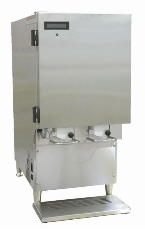
DISPENSER – COMPONENTS
These components will be referred to throughout this Manual.
Fill in Place flip-up
Lid
LCD Display
Power Indicator LED
Valve Block
Dispense
Lever
Splash
Panel
Power ON/OFF
Circuit Breaker
Catch
Tray
AC220-FP Self-Serve
Not all dispenser models have a Power LED on the front door. Fill in Place dispensers have a flip-up top lid.
Self-Serve dispensers that are not Fill in Place do not have a flip-up lid.
3

FLEXOSHOT AC220-FP Self-Serve Dispensers
FLEXOSHOT AC320-FP Self-Serve Dispensers
OPERATIONS MANUAL
Read this Manual Now…
Retain it for Future Reference
The FlexoShot by SureShot™ is a refillable two or three product, manually operated, refrigerated liquid dispenser with “Fill-in-Place” capability. Plastic tanks may be filled easily while in place in the dispenser. The refillable tanks are made of resilient polypropylene for excellent durability and clarity. The tanks provided with the dispenser are NSF-approved. Tank lids are to be used at all times.
Operating the dispenser is a simple 2-step process:
1.Place cup under the product delivery tube.
2.Press lever to deliver desired quantity of dairy product.
Safety Precautions
•Always plug the dispenser into an approved electrical outlet.
•The dispenser includes a microcontroller and must be operated on grounded electrical wiring at all times.
•Unplug the dispenser from its electrical source before servicing.
•Do not immerse the dispenser in water.
•Observe all safety precautions with this dispenser that you would with any electrical appliance.
Specifications |
AC220 |
AC320 |
Capacity: |
2 x 2.5 gal (10 L) |
1 x 2.5 gal (10 L) + 2 x 1.5 gal (5 L) |
Weight: |
75 lbs |
75 lbs |
Dimensions: L x W x H |
22” x 12” x 27” |
22” x 15½” x 27” |
Note: refillable containers only
height measured with standard 4” legs installed. 2½” and 1” legs are also available
Electrical Requirements
A/C Supply Voltage 120 VAC, 60 Hz, 3 amp, 1ph
The dispenser includes a microcontroller and must be operated at all times on grounded electrical wiring. Failure to do so will void the Warranty.
The power cord is furnished with a UL-approved 3-prong attachment plug. This plug is designed to fit a receptacle with provisions for a grounding stud.
NOTE – WARRANTY
The Warranty will be null and void if the dispenser is serviced by unqualified personnel. Service under Warranty must be approved and dispatched by A. C. Dispensing Equipment Inc. before the service technician is dispatched. Contact the SureShot Dispensing Systems® Technical Assistance Center at 1-888-777-9990 or 1-902-865-9602 for approval. The customer is responsible for all costs not approved by A. C. Dispensing Equipment Inc.
4
INSPECTION FOR DAMAGE
When you receive the dispenser, inspect the exterior of the shipping container for damage. Note any damage in detail.
Uncrate the dispenser at once (see instructions below). Examine the dispenser for damage. Report any damage to the transportation company immediately. File a claim for damages promptly.
Your immediate inspection protects you against loss since A. C. Dispensing Equipment Inc. is not responsible for damages incurred during shipment.
Notify A.C. Dispensing Equipment Inc. No returns will be accepted without prior approval. Obtain an authorized return number by contacting SureShot Dispensing Systems® Technical Assistance Center at 1-888-777-9990 or 1-902-865-9602.
RESHIPMENT
Packaging for re-shipment is done in the reverse order of uncrating. If packaging is not available, it can be purchased locally, or from our factory by request. Any damage occurring in transit of the returned goods caused by improper packaging is not considered a defect covered by Warranty.
SERVICING - ELECTRICAL
Electrical servicing must be carried out by a qualified technician. The Warranty will be null and void if the dispenser is serviced by unqualified personnel. Service under Warranty must be approved and dispatched by A. C. Dispensing Equipment Inc. before the service technician is dispatched. If you need assistance, call the SureShot Dispensing Systems® Technical Assistance Center at 1-888-777-9990 or 1-902-865-9602.
SERVICING - REFRIGERATION
The temperature is set at the factory to maintain products within the range of 35°F to 40°F (1.6°C to 4.4°C).
Any servicing of the refrigeration system must be carried out by a qualified technician. The Warranty will be null and void if the refrigeration system is serviced by unqualified personnel. Service under Warranty must be approved and dispatched by A. C. Dispensing Equipment Inc. before the service technician is dispatched. If you need assistance, call the SureShot Dispensing Systems® Technical Assistance Center at 1-888-777-9990 or 1-902-865-9602.
UNCRATING THE DISPENSER
CAUTION: Always lift the dispenser from the bottom. Do not lift the dispenser by the door – that may damage the dispenser.
To uncrate, follow these instructions:
1.Make sure the box is positioned with the arrow pointing upward.
2.Cut the packing straps at the top of the box.
3.Lift the top tray off the box.
4.Lift the center sleeve off the box.
5.Remove the protective corner inserts from the bottom tray.
6.Lift the dispenser by its bottom out of the tray. Always use two people to lift the dispenser.
7.Remove the plastic protective covering from the stainless steel exterior of the dispenser, by peeling it off. To peel, hold the dispenser firmly at the top and peel from top to bottom.
8.Prior to use, read the Operations Manual. Store it for future use.
NOTE: The carton top, sleeve, and bottom tray may be stored for future shipping.
5
1. OPERATIONS
INSTALLATION AND LOCATION OF THE DISPENSER
1. Location of Dispenser:
1.Place the dispenser where it will best serve your operation.
•Do not block the vents at the top rear of the dispenser or under the dispenser. The vents must be free and open to ensure proper operation of the ventilation system and to prevent over-heating and damage to the system.
2.Make sure that counters, platforms, and shelves are strong enough to support the dispenser and full containers of product.
3.Place the dispenser at the appropriate serving height so that staff drawing product from the dispenser can operate the levers as well as easily place and remove cups.
4.The dispenser must be placed on a level surface or leveled by adjusting the legs. The dispenser must be level to ensure proper functioning of the refrigeration system. Use a bubble level to ensure accuracy.
5.Do not remove the legs from the dispenser or allow the dispenser to sit flat on the counter.
•Airflow and circulation under the machine are essential for the proper operation of the refrigeration system.
•Make sure the legs at the four corners of the bottom of the dispenser are in place. If one has loosened during shipping, re-tighten it. Some dispenser models have adjustable legs and these legs are secure even though they may appear to be loose.
•Removal of the legs automatically voids the Warranty.
6.The dispenser is not suitable for outdoor use.
STARTING THE DISPENSER
CAUTION: Before starting the dispenser, make certain that all Installation instructions have been followed and that the dispenser has been sitting upright for a minimum of 3 hours.
To start the dispenser:
1.Plug the power cord into the proper electrical outlet.
2.Turn the Power Switch “ON”.
•Make sure the dispenser door is closed.
•If the dispenser is equipped with a Power Indicator Light (see page 3), the LED on the front door will glow green to indicate that the power is on.
•Check the LCD Display – a display indicates the dispenser is operating.
3.The temperature control has been pre-set at the factory. Allow the dispenser to run empty for one hour to achieve a cold temperature before placing product containers in the dispenser.
•You can feel the cold temperature by placing your hand on the top or back wall of the inside of the refrigeration compartment.
4.If the dispenser does not appear to be getting cold, check to make sure that it is plugged in and that the power source is active. If the dispenser still does not operate, immediately call the A. C. Dispensing Equipment Inc. Technical Assistance Center at 1-888-777-9990 or 902-865-9602.
CLEAN BEFORE FIRST USE
•Make sure you clean the dispenser thoroughly. See Cleaning Instructions for the Exterior of the Dispenser and the Dispenser Components on pages 9 - 11.
•The dispenser must not be cleaned by water jet.
6

LOADING THE DISPENSER: Product Tanks
Ensure the dispenser has achieved proper operating temperature by running empty for one hour before loading.
•All product tanks must be cleaned properly, sanitized with an approved sanitizing solution according to the manufacturer’s specifications, and air-dried before they are loaded into dispensers. Follow cleaning instructions on page 11.
•The power switch must be ON when tanks are loaded into the dispenser.
•Dispensers are shipped with a supply of pre-cut dispensing tubes or crimped-end dispensing tubes. Additional tubes may be ordered from your supplier.
•Tanks should be filled with pre-chilled product. Product installed above 40 ºF or 4.4 ºC may cause temperature display readings outside the acceptable 32° - 40° F (0° - 4.4°C) range.
1.Sanitize your hands or wear clean gloves to install product tank, cover, and tube.
2.Install the dispensing tube onto the tank spout.
Push the cut end of the tube onto the outlet spout at the bottom front of the cleaned product tank.
Push the tube all the way to the top, to completely cover the spout.
Attach a new dispensing tube every time the tank is cleaned.
3.Open the product compartment door.
Open the product dispensing valve door by turning the knob-screw counterclockwise.
4.Install cleaned tanks (follow instructions for your dispenser type).
•Install the appropriate tank for each product valve.
•Align the tube in the central vertical groove of the valve block.
•Remove the plastic film covering the tube.
For Fill in Place dispensers (tanks with pre-cut tubes):
Place the tank with lid in the dispenser, with the product delivery tube facing front.
For tanks with pre-crimped dispensing tubes:
Fill the tank with pre-chilled dairy product.
•Fill to the FULL level with product chilled to 40°F (4.4°C) or less.
Place the tank with lid in the dispenser, with the product delivery tube facing front.
5.Close the dispensing valve door, by turning the knob-screw in a clockwise motion until the door is snug. Do not over tighten the knob screw.
Make sure the tube is in the vertical groove and is not twisted or pinched during installation.
Do 6A or 6B, depending on your dispenser type: 6A. For Fill in Place dispensers only:
Open the front door of the dispenser and flip open the top access door on the tank to gain access to the tank lid.
Flip up the tank lid for the tank to be filled.
Fill tank to the FULL level with product chilled to 40°F / 4.4°C or less.
OR
6B. For dispensers with pre-crimped tubes:
Carefully cut the product delivery tube at a 45° angle at a maximum length of 5/8” from the bottom of the valve block. Cut the tube smoothly, with no jagged edges. Retain the other portion of the tube for later use.
7.Close the tank lids. Close the top access door on Fill in Place dispensers.
8.Close the dispenser door.
The dispenser is ready for use.
7
To Fill or Refill Tanks in Place:
1.Open the front door of the dispenser.
2.Flip up the access door on the top of the dispenser to gain access to the tank lid.
3.Open the lid on the tank to be re-filled.
4.Fill or Refill the tank to any desired level with product chilled to 41 °F / 5 °C or less.
5.Close tank lid.
6.Close the top access door.
7.Close the dispenser door.
To Remove an Empty Product Tank:
1.Place a container under the dispensing valve to catch any residual product and to prevent spills.
2.Open the valve door by unscrewing the knob-screw in a counter-clockwise motion.
3.Remove the empty tank while pinching the product delivery tube so that it does not drip.
4.Remove the product delivery tube and discard it.
5.Wash, rinse, sanitize and air dry the product tank, following cleaning instructions on page 12. For loading instructions, see page 7.
OPERATING INSTRUCTIONS
To Dispense Product:
1.Place cup under product delivery tube for product to be dispensed.
2.Press lever down and hold until desired volume is dispensed.
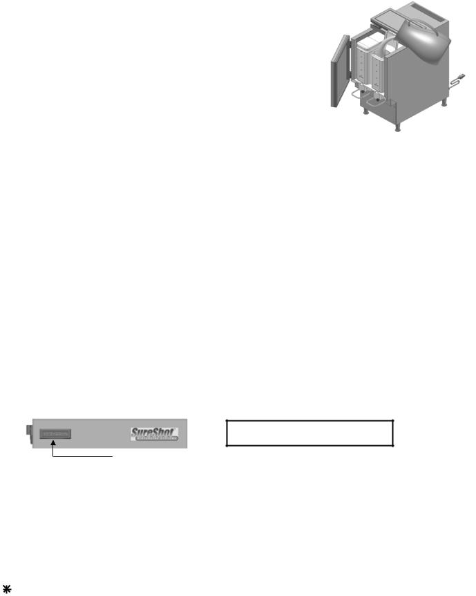
LCD DISPLAY
SURESHOT 37F
LCD Display
The LCD (Liquid Crystal Display) on the upper left corner of the dispenser door shows the current temperature of the refrigeration compartment. The temperature refers to the internal temperature of the refrigeration compartment, not the product temperature.
Temperature:
The temperature shows the internal temperature of the refrigeration compartment in degrees Fahrenheit (°F) or degrees Celsius (°C).
The display shows the temperature and the status of the refrigeration system.
Every two seconds, the display toggles between the temperature (approximately 37 °F or 2.8 °C) and: Blank - indicates the refrigeration cycle is off and the temperature is within the required range
-- indicates the refrigeration system is on and the temperature is cooling
DEF |
- indicates the defrost cycle is in progress and the refrigeration compartment is defrosting |
8

CLEANING
Do not spray any liquid, such as a cleaner, in or around the valve area.
Liquid could damage electrical components located behind the valve.
The dispenser must not be cleaner by water jet.
•Immediately clean up all product spilled during the filling process.
•Wipe the valve assembly with a towel dipped in sanitizer solution.
•Dispensers for Dairy Products: Empty, clean and sanitize the entire dispenser every 3 days (every 72 hours).
•New product dispensing tubes must be installed each time a tank is removed for cleaning (do not reuse tubes).
•Disassemble the valves and clean thoroughly once a week (see instructions below).
•Failure to follow these procedures may cause the dispenser to malfunction.
RECOMMENDED CLEANING SCHEDULE:
DISPENSER PART |
FREQUENCY |
SEE PAGES |
Catch Tray |
Daily |
9 |
Valve area |
Daily |
9 |
Dispensing valves |
Once a week, or as needed |
10 |
Exterior |
Weekly |
11 |
Product Tank |
Every time tank is removed |
11 |
Refrigerated Product Compartment |
Every time a new product tank is |
11 |
|
loaded |
|
Condenser |
Every 6 months |
11 |
CLEANING: Catch Tray
1.Remove the catch tray.
2.Disassemble the tray.
2.Rinse the tray parts with lukewarm potable water.
3.Place the tray parts in a hot water wash at a minimum water temperature of 140ºF or 60ºC. A good quality general cleaner should be added to the hot wash water at the concentrations recommended by the detergent supplier. Wash thoroughly, using a bottle brush to reach all the corners and crevices.
If a dishwasher is available at the location, this step may be carried out by placing the tray parts in the dishwasher and washing on the pot cycle.
4.After washing, rinse the tray parts well with lukewarm potable water.
5.Turn the tray parts upside down. Air dry.
CLEANING: Valve Area
The area around the product delivery valve should be wiped clean daily.
The front of the dispenser should be wiped clean daily.
To clean the valve area:
1.Empty the tanks at the end of the day.
2.Open the door to the refrigerated product compartment.
3.Open the valve door by unscrewing the knob in a counter-clockwise motion.
4.Remove tanks.
5.Thoroughly wipe the area around the valve with a warm, soapy cloth to remove any splashes or product build-up.
6.Wipe the area with a damp cloth to remove any soap residue.
7.Dry thoroughly.
8.Close the valve door.
9.Close door to refrigerated product compartment.
9

CLEANING: Remove & Clean the Dispensing Valve Assembly – Self-Serve Dispensers
NOTES: Prepare a container of warm, soapy water before you take the valve apart for cleaning.
Be careful not to dislodge the cable during cleaning.
1.Turn the power to the dispenser OFF.
2.Drain product tanks and remove empty tanks.
3.Open the door to the refrigerated product compartment.
4.Remove the catch tray (if applicable) by lifting it up and off.
5.Remove the 4 screws that secure the front splash panel in place and carefully remove the front splash panel. It is located below the white plastic valves that hold the product tubes. It is held in place by 4 screws. Thoroughly wash the splash panel.
6.Open the valve door: unscrew the black knob in a counter-clockwise motion.
7.Remove the Phillips-head screw which retains the aluminum insert. Do not misplace the screw.
Wipe the insert and screw clean.
8.Remove the 2 screws at the upper corners of the valve block. Do not misplace the screws.
9.Remove the white valve body. Hold the valve carefully with one hand so that the thermistor wire will not be broken or damaged. The steel handle comes off with the valve body.
NOTE: The valve body can only be moved the length of the thermistor wire, which is located in the left valve. It is essential that the thermistor wire be
replaced on the left side to ensure proper refrigeration process. 10. Remove the plunger tip and spring.
Wash, rinse, sanitize, and air dry the plunger tip and spring. 11. Wipe the spring cup clean.
12. Wash the handle, plunger tip and spring in warm, soapy water. Rinse with clear water. Dry thoroughly.
13. Clean the white plastic sections of the valve block, using a small brush with warm, soapy water. Dry thoroughly.
14. Clean the valve door front, valve door back, and insert. 15. Put the spring and plunger back together so that you can
reassemble the valve body.
16. Align the valve body with the plunger. Move back into place. 17. Replace the 2 screws. Tighten until snug.
18. Replace the screw at the top of the metal valve insert. This screw must fit snugly to ensure proper operation of the refrigeration system.
Do not over-tighten the screw.
19. Close the valve door.
20. Secure the door by tightening the knob-screw in a clockwise motion until the door is snug. Do not over-tighten the screw.
21. Re-install the 4 screws to secure the front panel in place. 22. Wipe the refrigerated product compartment clean.
23. Close the refrigerated product compartment door.
The dispenser is ready to operate once you load new product.
Step 5
Step 7
Step 8
Step 9
10
CLEANING: Exterior of Dispenser
NOTE: Do not use any abrasive materials.
1.Use a soft, dry cloth to wipe down the exterior surfaces of the dispenser to maintain the luster of the stainless steel finish.
2.Wash the stainless steel exterior surfaces of the dispenser with warm, soapy water. Rinse with warm clear water. If the water is hard, wipe the dispenser dry with a soft cloth to prevent water spotting. Stainless steel polish may be used if it is sprayed on a cloth before the cloth is used to wipe down the exterior surfaces of the dispenser.
CLEANING: Product Tanks and Covers
•Product tanks and covers are made of plastic. Tanks and covers may be washed in a dishwasher or by hand according to state and provincial regulations. If washing by hand, a pot brush is recommended.
•Cleaning requirements may be specified by company policy or local regulation.
•Tanks for Fill-in-Place dispensers must be cleaned to your company’s specifications at regular intervals specified by local authority.
To clean the product tank:
1.When the product has run out, remove the tank from the dispenser. Remove the product delivery tube from the tank.
Discard the tube.
Rinse the tank, including the cover, with lukewarm potable water.
2.Place the tank and cover in a hot water wash at a minimum water temperature of 140ºF or 60ºC.
A good quality general cleaner should be added to the hot wash water at the concentrations recommended by the detergent supplier.
Wash thoroughly, using a bottle brush to reach all the corners and crevices. Wash the outlet spout area, using a small bottle brush.
If a dishwasher is available at the location, this step may be carried out by placing the tank and cover in the dishwasher and washing on the pot cycle.
3.After the tank and cover have been washed, rinse well with lukewarm potable water.
4.Turn the tank and cover upside down. Air dry.
5.Before refilling the tank with product, sanitize the tank and cover with mild sanitizer such as chlorine at 100 ppm, or a product recommended by your detergent supplier.
Let the tank and cover drain before filling with product. Do not rinse.
6.Just before installing the tank in the dispenser, apply a new white dairy tube to the outlet spout of the tank.
CLEANING: Refrigerated Product Compartment of Dispenser
•Wipe the compartment clean each time a new tank is loaded. This will remove any condensation that may accumulate within the compartment.
1.Each time a new tank is loaded, check the refrigerated product compartment for ice build-up. If ice has accumulated in the refrigerated product compartment:
Leave the dispenser door open. Turn the dispenser OFF
Wait 10 minutes for the ice to soften. Gently remove and discard the ice.
2.Wipe the interior down with a soft cloth.
3.Dry thoroughly.
4.Turn the dispenser back ON (if the dispenser was turned OFF in Step 1).
CLEANING: The Condenser
Every 6 months, remove the back panel of the dispenser and inspect the condenser. If necessary, clean the condenser using a vacuum. We suggest a vacuum be used to prevent any damage to the condenser coil.
11
 Loading...