


AC10-PC
Refrigerated Liquid
Dispensers
Service Manual
D-19-030RevA
1

Model |
Products |
Function |
Button Panels |
Weight |
Dimensions |
Capacity |
AC10-PC |
1 |
portion control |
1, 3, 4, 5 |
60 lbs |
17¾ x 9½ x 24 |
1 x 2½ gal (1 x 10 L) |
|
|
|
|
|
|
|
NOTES: All Dimensions are in inches, with standard 1” legs installed.
Power Supply – all dispensers: 120 VAC, 1 ph, 60 Hz, 3 amp
|
A.C. Dispensing Equipment Inc. |
Technical Assistance Center: |
|
100 Dispensing Way |
1-888-777-9990 or 1-902-865-9602 |
|
Sackville, Nova Scotia Canada |
OR service@sureshotdispensing.com |
|
B4C 4H2 |
|
2
Table of Contents
Dispenser Components
Specifications
Safety Precautions
Inspection for Damage
Reshipment
Uncrating the Dispenser
Electrical Requirements
Servicing – Electrical
Servicing – Refrigeration
Installation of the Dispenser
1.OPERATIONS
Clean Before First Use Starting the Dispenser Loading the Dispenser
Loading Product Bags
To Remove an Empty Product Bag or Tank To Dispense
Button Panels
Red Indicator Light LCD Display
2.CLEANING
Recommended Cleaning Schedule
Cleaning – Catch Tray
Cleaning – Valve Area
Cleaning – Exterior of Dispenser
Cleaning – Dispensing Valve Area
Cleaning – Dispensing Valve Assembly
Cleaning – Product Tanks & Caps
Cleaning – Product Case
Cleaning – Refrigerated Compartment
Cleaning – Condenser
3.REFRIGERATION SYSTEM
Temperature Control Adjustment Dispenser Running Too Cold Dispenser Running Too Warm
4.MAINTENANCE
To Reset the Power on the Dispenser General Maintenance
5. TECHNICAL SERVICE
Level Dispenser
Remove Valve Cover
Remove Dispenser Door
Remove & Replace LCD Display
Remove & Replace Valve
Remove & Replace Valve Thermistor
Remove & Replace Display Thermistor
Remove & Replace Circuit Board
Remove & Replace Compressor Relay
Remove & Replace Transformer
2 |
Remove & Replace Circuit Breaker |
22 |
|
2 |
Remove & Replace ON/OFF Switch |
22 |
|
4 |
Remove & Replace Solenoid |
23 |
|
4 |
Remove & Replace Condenser Fan |
24 |
|
4 |
Remove Back Panel |
24 |
|
5 |
Replace Electrical Cord |
24 |
|
5 |
|
|
|
5 |
6. CHECKS AND ADJUSTMENTS |
|
|
5 |
AC Outlet for 120 VAC |
25 |
|
5 |
AC 120 VAC input to Transformer |
25 |
|
|
AC 24/12 VAC output to PCB from Transformer |
25 |
|
6 |
DC 2.8 Æ 3.8 VDC input of Valve Thermistor |
26 |
|
Resistance of Valve Thermistor |
26 |
||
6 |
DC 2.8 Æ 3.8 VDC input of Display Thermistor |
26 |
|
6 |
Resistance of Display Thermistor |
26 |
|
7 |
38 DVC output to Solenoid |
27 |
|
8 |
38 DVC output to the Compressor Relay |
27 |
|
8 |
120 VAC input to Compressor Back |
27 |
|
8 |
Proximity Switch Continuity Check |
28 |
|
9 |
Quantity Volume Checks |
28 |
|
9 |
To Adjust Dispense Amounts |
28 |
|
|
Displayed Temperature Offset Check |
29 |
|
10 |
Displayed Temperature Adjustment |
29 |
|
Gas Pressure Check |
29 |
||
10 |
|||
|
|
||
10 |
7. DIAGRAMS |
|
|
10 |
|
||
Wiring Diagram |
30 |
||
11 |
|||
Electrical System |
31 |
||
12 |
|||
Circuit Board – labeled picture |
32 |
||
13 |
|||
General Assembly |
33 |
||
13 |
|||
|
|
||
13 |
8. PARTS LIST |
34 |
|
13 |
|||
|
|
||
14 |
9. TROUBLESHOOTING |
|
|
Dispenser is not level |
35 |
||
14 |
|||
No power at the plug |
35 |
||
15 |
|||
Dispenser will not turn on |
35 |
||
15 |
|||
Dispenser will not dispense product |
35 |
||
|
|||
|
Dispenser is not dispensing proper amount |
|
|
16 |
of product |
36 |
|
16 |
Valve is sticky |
36 |
|
|
Valve door is broken |
36 |
|
|
Dispenser is warm on exterior |
37 |
|
17 |
Dispenser is warm on interior |
37 |
|
17 |
Dispenser is too cold |
37 |
|
17 |
Frost buildup in refrigeration compartment |
37 |
|
18 |
Dispenser is leaking product |
38 |
|
19 |
LCD does not come on |
38 |
|
19 |
10. WARRANTY |
39 |
|
20 |
|||
20 |
|
|
|
21 |
|
|
|
21 |
Document # D-19-030 RevA |
||
3
AC10-PC LIQUID DISPENSERS - OPERATIONS
The AC10-PC SureShot Dispensing Systems® Liquid Dispensers provide refrigerated liquids such as cream, whole milk, skim milk, in automatically controlled portions. Product selections are made using touch buttons on the front panel. Each button is pre-set independently at our factory to dispense a specified amount of refrigerated product in accurate, portion-controlled quantities to your company’s specifications. The product is stored in a sanitary, refrigerated compartment within the dispenser.
The AC10-PC model will dispense a dairy product in up to five different sizes from touch buttons on the front of the dispenser.
Operating the dispenser is a simple two-step process:
1.Place cup under the product delivery tube.
2.Press button for the desired quantity of dairy product.
Safety Precautions
•Always plug the dispenser into an approved electrical outlet.
•The dispenser includes a microcontroller and must be operated on grounded electrical wiring at all times.
•Unplug the dispenser from its electrical source before servicing.
•Do not immerse the dispenser in water.
•Observe all safety precautions with this dispenser that you would with any electrical appliance.
INSPECTION FOR DAMAGE
When you receive the dispenser, inspect the exterior of the shipping container for damage. Note any damage in detail.
Uncrate the dispenser at once (see instructions below). Examine the dispenser for damage. Report any damage to the transportation company immediately. File a claim for damages promptly.
Your immediate inspection protects you against loss since A. C. Dispensing Equipment Inc. is not responsible for damages incurred during shipment.
RESHIPMENT
Packaging for re-shipment is done in the reverse order of uncrating. If packaging is not available, it can be purchased locally, or from our factory by request. Any damage occurring in transit of the returned goods caused by improper packaging is not considered a defect covered by Warranty.
NOTE: The Warranty will be null and void if the dispenser is serviced by unqualified personnel. Service under Warranty must be approved and dispatched by A. C. Dispensing Equipment Inc. before the service technician is dispatched. Contact the SureShot Dispensing Systems® Technical Assistance Center at 1-888-777-9990 or 1-902-865-9602 for approval. The customer is responsible for all costs not approved by A. C. Dispensing Equipment Inc.
4

UNCRATING THE DISPENSER
CAUTION: Always lift the dispenser from the bottom. Do not lift the dispenser by the door. To uncrate:
1.Make sure the box is positioned with the arrow pointing upward.
2.Cut the packing straps at the top of the box.
3.Lift the top tray off the box.
4.Lift the center sleeve off the box.
5.Remove the protective corner inserts from the bottom tray.
6.Lift the dispenser by its bottom out of the tray. Always use two people to lift the dispenser.
7.Remove the plastic protective covering from the stainless steel exterior of the dispenser, by peeling it off. To peel, hold the dispenser firmly at the top and peel from top to bottom.
8.Prior to use, read the Operations Manual. Store it for future use.
NOTE: The carton top, sleeve, and bottom tray may be stored for future shipping.
ELECTRICAL REQUIREMENTS
Be sure the current at the power source receptacle is: 120 VAC, single phase, 3 Amp, 60 Hz.
The power cord is furnished with a UL-approved 3-prong attachment plug. This plug is designed to fit a receptacle with provisions for a grounding stud. The dispenser includes a microcontroller and must be operated on grounded electrical wiring at all times. Failure to do so will void the Warranty.
SERVICING - ELECTRICAL
Electrical servicing must be carried out by a qualified technician. The Warranty will be null and void if the dispenser is serviced by unqualified personnel. If you need assistance, call the SureShot Dispensing Systems® Technical Assistance Center at 1-888-777-9990 or 1-902-865-9602.
SERVICING - REFRIGERATION
Any servicing of the refrigeration system must be carried out by a qualified technician. The Warranty will be null and void if the refrigeration system is serviced by unqualified personnel. If you need assistance, call the SureShot Dispensing Systems® Technical Assistance Center at 1-888-777-9990 or 1-902-865-9602.
INSTALLATION AND LOCATION OF THE DISPENSER
1.Location of Dispenser:
•Place the dispenser where it will best serve your operation.
•Counters, platforms, or shelves should be strong enough to support the dispenser and full containers of product. The empty AC10-PC dispenser weighs 60 pounds.
•Place the dispenser at the appropriate serving height so that people drawing product from the dispenser can operate the buttons as well as easily place and remove cups.
•Leave clear space around the dispenser, approximately 1 inch (2.5 cm) on all sides.
•Do not place the dispenser too close to a source of heat or moisture. Allow a minimum 1 inch (2.5 cm) airspace between machines at all times. The performance and efficiency of the refrigeration system will be reduced if the dispenser is placed too close to a heat-generating machine, such as a coffeemaker.
•Do not block the vents at the top rear of the dispenser. The vents must be free and open to ensure proper operation of the ventilation system and to prevent over-heating and damage to the system.
•The dispenser must be placed on a level surface or leveled by adjusting the legs. Not all dispensers have adjustable legs. The dispenser must be level, left to right and front to back, to dispense accurate quantities and to ensure proper functioning of the refrigeration system.
•Do not remove the legs or rubber feet from the dispenser or allow the dispenser to sit flat on the counter. Airflow and circulation under the machine are essential for the proper operation of the refrigeration system. Make sure the legs at the four corners of the bottom of the dispenser are in place. If one has loosened during shipping, re-tighten it. Some dispenser models have adjustable legs and these legs are secure even though they may appear to be loose. Removal of the legs automatically voids the Warranty.
5

1. OPERATIONS
CLEAN BEFORE FIRST USE OF THE DISPENSER
•Make sure you clean the dispenser thoroughly. See Cleaning Instructions for the Exterior of the Dispenser and the Dispenser Components on pages 10 - 13.
CAUTION: Before starting the dispenser, make certain that all Installation instructions have been followed and that the dispenser has been sitting upright for a minimum of 3 hours.
STARTING THE DISPENSER
To start the dispenser:
1.Plug the power cord into the proper electrical outlet.
2.Turn the Power Switch “ON”. The power switch is located at the lower left of the dispenser. Make sure the dispenser door is closed.
Push one of the product buttons on the front panel and listen to hear the valve open and close. This confirms that the dispenser is operating. The button panel on the front of the dispenser may have a power LED which glows green when the dispenser is on.
3.Allow the dispenser to run empty for one hour to achieve a cold temperature before placing product containers in the dispenser. The temperature control has been pre-set at the factory.
You can feel the cold temperature by placing your hand on the top or back wall of the refrigeration compartment.
4.If the dispenser does not appear to be getting cold, check to make sure that it is plugged in and that the power source is active. If the dispenser still does not operate, immediately call the SureShot Dispensing Systems® Technical Assistance Center Technical Assistance Center at 1-888-777-9990 or 1-902-865-9602.
LOADING THE DISPENSER
•Ensure the dispenser has achieved proper operating temperature by running empty for one hour before loading product to be dispensed.
•Product being placed inside the refrigeration compartment should be cooler than 41 ºF or 5 ºC.
•The product is supplied in sanitary pre-packaged bags with attached delivery tubes. The bags are
placed in product cases that are placed within the refrigeration compartment.
.
6

LOADING: Product Bags
NOTE: Product may be loaded in bags, bags in boxes, or in tanks.
•All product tanks must be cleaned properly, sanitized with an approved sanitizing solution according to the manufacturer’s specifications, and air-dried before they are loaded into dispensers. Follow cleaning instructions on page 13.
•Tanks are to be loaded into the dispenser with the power switch ON.
•Tanks should be filled with chilled product before they are loaded
into the dispenser. Fill to the FULL level with product chilled to 41 °F (5 °C) or less.
•Sanitize your hands or wear clean gloves to install product tank, tank cover, and delivery tube.
Sanitize your hands or wear clean gloves to load the dispenser.
1.Place the bagged product in the product case provided with the dispenser. Make sure the bag fitment is positioned so the product delivery tube is inserted through the opening at the bottom front of the case and is perpendicular to the dispensing valve.
2.Open the door to the refrigerated product compartment.
3.Open the valve door by unscrewing the black knob in a counter-clockwise motion to loosen the screw.
4.Insert the product case into the refrigerated product compartment, with the tube facing out to the front.
5.Make sure there are no kinks or twists in the product delivery tube.
6.Remove the polyethylene film covering the product delivery tube.
7.Align the product delivery tube in the central vertical groove of
the valve block. |
Loading product bag |
Do not pull or stretch the product delivery tube. |
|
8.Close the valve door, making sure the product delivery tube is in the vertical groove and is not kinked or pinched.
9.While holding the valve door closed with one hand, tighten the knob-screw in a clockwise motion until the door is snug.
Do not overtighten the screw.
10.Close the refrigerated product compartment door.
11.Squeeze the product delivery tube just below the valve with all fingertips.
12.While squeezing the tube, press the “small” product quantity button on the front door button panel once only. This will cause the valve to operate once and relieve pressure in the tube.
13.Use sharp scissors or a sharp knife to carefully cut the product delivery tube at a 45° angle at a maximum length of 5/8” from the bottom of the valve block.
Discard the cut portion of the tube.
The dispenser is ready for use.
Tube alignment
7 |
Cut tube |
To Remove an Empty Product Bag or Tank:
1.Place a container under the dispensing valve to catch any residual product and to prevent spills.
2.Open the valve door by unscrewing the knob in a counter-clockwise motion.
3.Remove the empty bag or tank while pinching the product delivery tube so that it does not drip. Discard the empty product bag.
4.EMPTY TANK: Wash, rinse, sanitize and air-dry the product tank, using cleaning instructions on page 13.
OPERATING INSTRUCTIONS – AC10-PC Dispensers
•Make certain all initial Set-Up instructions have been followed before operating the dispenser.
•The product and volume to be dispensed are selected by pressing buttons on the Button Panel on the front door of the dispenser.
•Select buttons as required.
To Dispense Product:
1.Place cup under product delivery tube.
2.Press button to select product quantity to be dispensed.
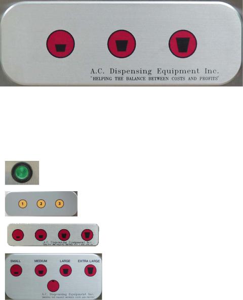
One Size |
|
|
|
Three Sizes: |
1 |
2 |
3 |
|
small |
medium |
large |
Four Sizes: |
Small |
Medium |
Large X-Large |
TOP: Small Medium Large X-Large
BOTTOM: Modifier Button
1.Press Modifier Button to dispense quantities for modifier amounts
2.Press top row button to select size of product dispensed
8
RED INDICATOR LIGHT
Some dispensers have a 5-button panel. The bottom row button is a Modifier Button for dispensing quantities for specialty Modifier amounts. The Modifier Button has a Red Indicator Light (red LED) at the top.
The Indicator Light will light for three seconds after the Modifier Button is pressed, to indicate that the size selected will be dispensed in Modifier amounts.
The Indicator Light will flash to indicate the Modifier Button is in program mode (see page 28).
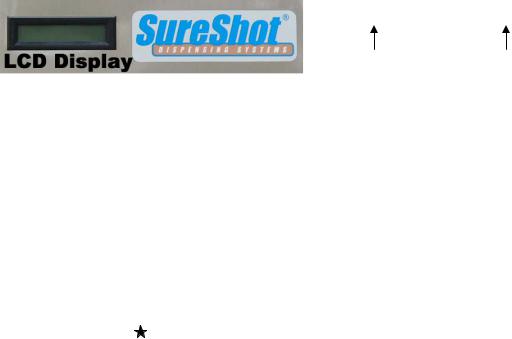
LCD DISPLAY – AC10-PC Dispensers
SureShot |
37 F |
|
|
Operation Temperature
SureShot Dispensing Systems ® liquid dispensers use a Liquid Crystal Display in the upper left corner of the dispenser door to show the current dispenser function.
Note: not all dispensers have an LCD.
Information is displayed in two parts:
Operation – shows the current operating function of the dispenser
Temperature – shows the internal temperature of the refrigeration compartment. (NOTE: this is the compartment temperature in Celsius or Fahrenheit degrees, not the product temperature.)
Temperature:
Continuously shows the internal temperature status of the refrigeration compartment in Celsius or Fahrenheit degrees, at your company’s specifications. The display changes every 3 seconds.
Examples: |
37 F |
37 degrees Fahrenheit |
|
(blank) |
refrigeration system off |
|
|
refrigeration system on |
|
DEF |
defrost cycle in progress |
Operation:
Press the button to Select Product. The LCD shows the operational status of that product tank or case:
Display |
Operational Status |
SureShot 37 F |
indicates the dispenser is ready to dispense |
|
and the internal compartment temperature is 37 °Fahrenheit |
TR1 |
If the valve door is opened and closed, the dispenser resets the product |
|
level for the case or tank dispensed by that valve. This display shows that |
|
the level has been reset to Full for the tank/case. |
Small |
Indicates the size selected, if Size button is pressed. |
Medium |
The LCD displays the size to be dispensed to your company’s specification. |
Large |
Not all dispensers have the Extra Large option. |
Extra Large |
|
NOTES:
•Display returns to SureShot, the default display, after 3 seconds.
9

2.CLEANING
Cleaning of tanks is a 4-stage process: Rinse, wash, rinse, sanitize. All 4 stages must be followed, in sequence, to complete cleaning.
Do not spray any liquid, such as a cleaner, in or around the valve area.
Liquid could damage electrical components located behind the valve.
RECOMMENDED CLEANING SCHEDULE:
DISPENSER PART |
FREQUENCY |
SEE PAGES |
Catch Tray |
Daily |
10 |
Exterior |
Daily |
10 |
Valve area |
Daily |
10 |
Exterior |
Daily |
10 |
Dispensing valves - PC |
Once a month, or as needed |
11, 12 |
Product Case |
Every time valve is cleaned, or as required |
13 |
Refrigerated Product Compartment |
Every time a new product bag or tank is loaded |
13 |
Condenser |
Every 6 months |
13 |
CLEANING: Catch Tray
Note: Not all dispensers have a catch tray.
For some dispensers, the catch tray is a separate accessory placed at the front of the dispenser. For some dispensers, the catch tray is attached at the front and must be removed for cleaning, by lifting it up and off.
1.Rinse the tray with lukewarm potable water.
2.Place the tray in a hot water wash at a minimum water temperature of 140 ºF or 60 ºC.
•A good quality general cleaner should be added to the hot wash water at the concentrations recommended by the detergent supplier.
3.Wash thoroughly, using a bottle brush to reach all the corners and crevices.
•If a dishwasher is available at the location, this step may be carried out by placing the tray in the dishwasher and washing on the pot cycle.
4.After washing, rinse the tray well with lukewarm potable water.
5.Turn the tray upside down. Air dry.
CLEANING: Valve Area
1.Turn the dispenser OFF.
2.Open the door to the refrigerated product compartment.
3.Thoroughly wipe the area around the valve with a warm, soapy cloth or a sanitized handiwipe to remove any splashes or product build-up.
•Keep the valve area clean for proper sanitation and to ensure proper product delivery.
•If the valve area is not clean, the valve may stick and not deliver product accurately.
•Clean the valve assembly once a week, when the tank is empty.
•Wipe the valve area clean daily.
4.Wipe the area with a damp cloth to remove any soap residue.
5.Air dry thoroughly.
6.Close door to refrigerated product compartment.
7.Turn the dispenser ON.
CLEANING: Exterior of Dispenser
NOTE: Do not use any abrasive materials.
1.Use a soft, dry cloth to wipe down the exterior surfaces of the dispenser to maintain the lustre of the stainless steel finish.
2.Wash the stainless steel exterior surfaces of the dispenser with warm, soapy water.
3.Rinse with warm clear water.
•If the water is hard, wipe the dispenser dry with a soft cloth to prevent water spotting.
•Stainless steel polish may be used if it is sprayed on a cloth before the cloth is used to wipe down the exterior surfaces of the dispenser.
•The front of the dispenser should be wiped clean daily.
10
CLEANING: Valve Area & Valves – Portion-Controlled Dispensers
•The area around the product delivery valve must be kept clean, for proper sanitation and for the proper delivery of calibrated product amounts. If the valve area is not clean, the valve may stick and not deliver product accurately, or at all.
•The area around the product delivery valve should be wiped clean daily.
•It is necessary to remove the valve from the dispenser and take the valve apart to clean it (we recommend once a month or as needed), but it is an easy process if you follow the steps outlined on the following pages.
Valve Spring Retainer
Valve Spring
Valve Plunger
Valve Door Insert
Valve Door – Front
Valve Door Knob Screw
Flat-head Screw 1x
Machine Screw 2x
Valve Door – Back
Reed Switch/
Thermistor Wire
Front Panel
Valve Block
Pan-head Screw 4x
11
Valve Assembly
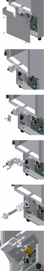
CLEANING: Remove & Clean Dispensing Valve Assembly
NOTES: Prepare a container of warm, soapy water before you take the valve apart for cleaning.
Be careful not to dislodge the cable during cleaning.
1.Turn the power to the dispenser OFF.
2.Open the dispenser door to the refrigerated product compartment.
3.Remove the product tanks by following the instructions on page ____.
4. Remove the catch tray (if applicable) by lifting it up and off.
5.Remove the 4 pan-head screws (+) that secure the front splash panel (valve cover) in place and carefully remove the panel. It is located below the white plastic valves that hold the product dispensing tubes. It is held in place by 4 phillips-head screws (+).
Thoroughly wash the splash panel.
6.Open the valve door: unscrew the black knob in a counter-clockwise motion.
7.Remove the phillips-head screw at the top of the metal valve insert. Do
not misplace the screw. Wipe clean.
8.Remove the 2 phillips-head screws at the upper corners of the valve block.
Do not misplace the screws. Wipe clean.
9.Gently remove the white valve body, using an even force.
Hold the valve carefully with one hand so that the thermistor wire will not be broken or damaged.
Do not let the valve dangle freely. Hold it in your hands.
NOTE: The valve body can only be moved the length of the thermistor wire.
10.Remove the plunger and spring.
Rinse, wash, rinse, sanitize, and air dry the plunger and the spring
11.Wipe the spring cup clean.
12.Clean the white plastic sections of the valve block, using a small brush with warm, soapy water.
Rinse, sanitize, and air dry the white plastic sections of the valve block with the plunger and spring. Air dry thoroughly.
13.Reassemble the spring, the plunger, and the valve body.
14.Align the valve body with the plunger. Move back into place.
15.Replace the 2 phillips-head screws. Tighten until snug.
Do not over-tighten the screws.
16.Replace phillips-head screw at the top of the metal valve insert. This screw must fit snugly to ensure proper operation of the refrigeration system. Do not over-tighten the screw.
17.Close the valve door.
18.Secure the door by tightening the knob-screw in a clockwise motion until the door is snug. Do not over-tighten the screw.
19.Re-install 4 phillips-head screws to secure the front panel in place.
20.Wipe the product compartment clean.
21.Close the refrigerated product compartment door.
22.Turn dispenser ON.
23.Push any “size” button.
Listen for the valve door open and close to ensure that the valve is operating properly.
24.Load new product and dispense.
Step 5
Step 6
Step 7
Step 9
Step 10
Step 13
12
 Loading...