


Refrigerated Liquid
Dispensers
Self-Serve Dispensers:
AC220-FP Fill-in-Place
AC320-FP Fill-in-Place
D-19-064 Rev A
SERVICE MANUAL

A
Dispenser Components 3
Safety Precautions 4
Specifications 4
Electrical Requirements 4
Inspection for Damage 5
Reshipment 5
Servicing – Electrical 5
Servicing – Refrigeration 5
Uncrating the Dispenser 5
1. OPERATIONS
Installation of the Dispenser 6
Starting the Dispenser 6
Clean Before First Use 6
Loading the Dispenser – Product Tanks 7
To Fill or Refill Tanks in Place 8
To Remove an Empty Product Tank 8
To Dispense 8
LCD Display 8
2. CLEANING
Recommended Cleaning Schedule 9
Cleaning – Catch Tray 9
Cleaning – Valve Area 9
Cleaning – Dispensing Valve Assembly -SS 10
Cleaning – Exterior of Dispenser 11
Cleaning – Product Tanks 11
Cleaning – Refrigerated Compartment 11
Cleaning – Condenser 11
3. REFRIGERATION SYSTEM 12
Temperature Control Adjustment 12
Dispenser Running Too Cold 13
Dispenser Running Too Warm 13
4. MAINTENANCE
General Maintenance 14
To Remove Ice Buildup 14
5. TECHNICAL SERVICE
Level Dispenser 15
Remove Splash Panel 15
Remove Dispenser Door 15
Remove & Replace LCD Display 16
Remove & Replace Valve 17
Remove & Replace Valve Thermistor 17
Remove & Replace Display Thermistor 18
Remove & Replace Circuit Board 18
Remove & Replace Compressor Relay 19
Table of Contents
Remove & Replace Transformer 19
Remove & Replace Circuit Breaker 20
Remove & Replace ON/OFF Switch 20
Remove & Replace Condenser Fan 21
Remove Back Panel 21
Replace Electrical Cord 21
6. CHECKS AND ADJUSTMENTS
AC Outlet for 120 VAC 22
AC 120 VAC input to Transformer 22
AC 24/12 VAC output to PCB from Transformer 22
DC 2.8 Æ 3.8 VDC input of Valve Thermistor 23
Resistance of Valve Thermistor 23
DC 2.8 Æ 3.8 VDC input of Display Thermistor 23
Resistance of Display Thermistor 23
38 VDC output to the Compressor Relay 24
120 VAC input to Compressor Back 24
Product Temperature Check 24
Displayed Temperature Offset Check 25
To Calibrate Displayed Temperature Offset 25
Product Temperature Adjustment 26
7. DIAGRAMS
Electrical System 27
Wiring Diagram 28
General Assembly 29
8. PARTS LIST 30
9. TROUBLESHOOTING
No power at the plug 31
Dispenser will not turn on 31
Dispenser is not level 31
Valve is sticky 31
Dispenser will not dispense product 31
Dispenser is not dispensing proper amount
of product 31
Valve door is broken 32
Dispenser is unusually warm on exterior 32
Dispenser is unusually warm on interior 32
Dispenser is too cold in the interior 32
Frost buildup in refrigeration compartment 32
Dispenser is leaking product 33
LCD Display on front door does not come on 33
Temperature display – blank or extreme 33
10. WARRANTY 35
A.C. Dispensing Equipment Inc.
100 Dispensing Way
Sackville, Nova Scotia Canada
B4C 4H2
D-19-064Rev
Technical Assistance Center:
1-888-777-9990 or 1-902-865-9602
OR service@sureshotdispensing.com
www.sureshotdispensing.com
2

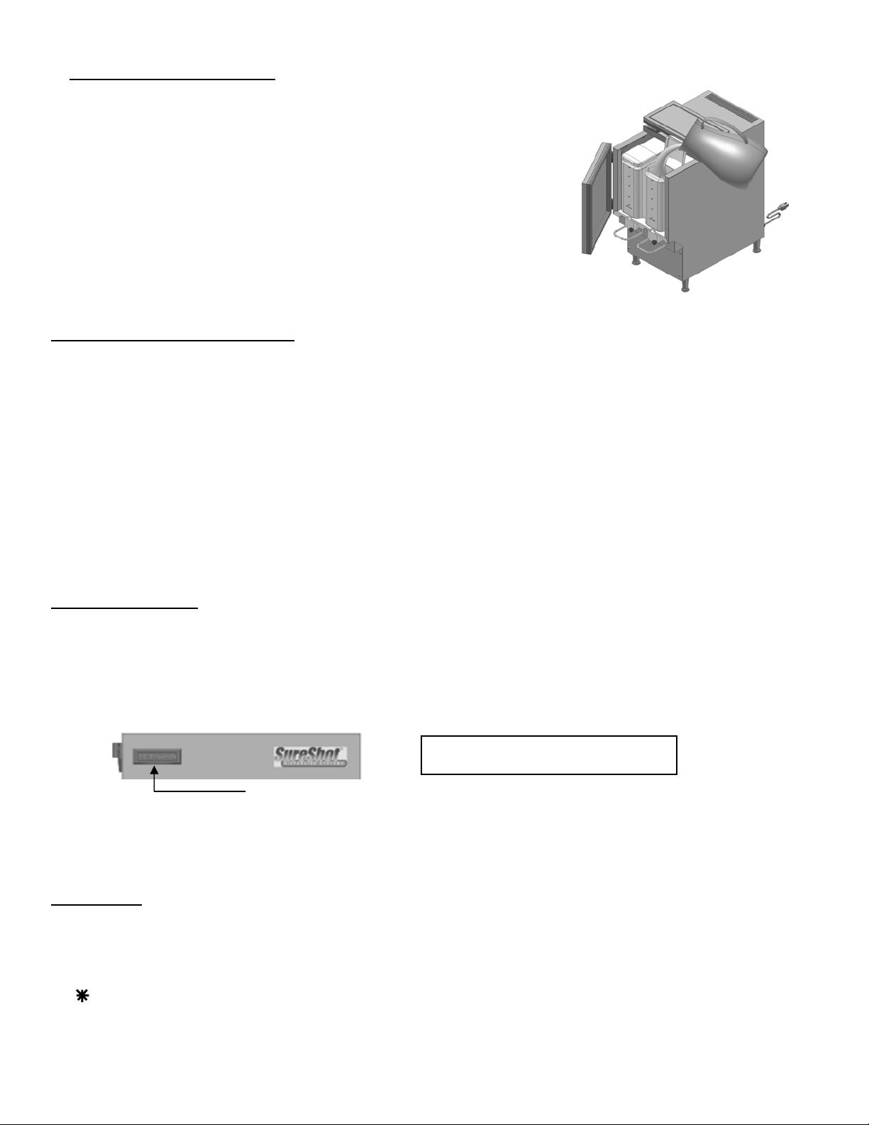
DISPENSER – COMPONENTS
These components will be referred to throughout this Manual.
Fill in Place flip-up
Lid
LCD Display
Dispense
Lever
Splash
Panel
Power ON/OFF
Catch
Tray
AC220-FP Self-Serve
Not all dispenser models have a Power LED on the front door.
Fill in Place dispensers have a flip-up top lid.
Self-Serve dispensers that are not Fill in Place do not have a flip-up lid.
3

p
The FlexoShot by SureShot™ is a refillable two or three product, manually operated, refrigerated liquid
dispenser with “Fill-in-Place” capability. Plastic tanks may be filled easily while in place in the dispenser. The refillable
tanks are made of resilient polypropylene for excellent durability and clarity. The tanks provided with the dispenser are
NSF-approved. Tank lids are to be used at all times.
Operating the dispenser is a simple 2-step process:
1. Place cup under the product delivery tube.
2. Press lever to deliver desired quantity of dairy product.
FLEXOSHOT AC220-FP Self-Serve Dispensers
FLEXOSHOT AC320-FP Self-Serve Dispensers
OPERATIONS MANUAL
Read this Manual Now…
Retain it for Future Reference
Safety Precautions
• Always plug the dispenser into an approved electrical outlet.
• The dispenser includes a microcontroller and must be operated on
grounded electrical wiring at all times.
• Unplug the dispenser from its electrical source before servicing.
• Do not immerse the dispenser in water.
• Observe all safety precautions with this dispenser that you would with
any electrical appliance.
Specifications AC220 AC320
Capacity: 2 x 2.5 gal (10 L) 1 x 2.5 gal (10 L) + 2 x 1.5 gal (5 L)
Weight: 75 lbs 75 lbs
Dimensions: L x W x H 22” x 12” x 27” 22” x 15½” x 27”
Note: refillable containers only
height measured with standard 4” legs installed. 2½” and 1” legs are also available
Electrical Requirements
A/C Supply Voltage 120 VAC, 60 Hz, 3 amp, 1ph
The dispenser includes a microcontroller and must be operated at all times on grounded electrical wiring. Failure to do
so will void the Warranty.
The power cord is furnished with a UL-approved 3-prong attachment plug. This plug is designed to fit a receptacle
with provisions for a grounding stud.
NOTE – WARRANTY
The Warranty will be null and void if the dispenser is serviced by unqualified personnel. Service under Warranty must
be approved and dispatched by A. C. Dispensing Equipment Inc. before the service technician is dispatched. Contact
the SureShot Dispensing Systems® Technical Assistance Center at 1-888-777-9990 or 1-902-865-9602 for approval.
The customer is res
onsible for all costs not approved by A. C. Dispensing Equipment Inc.
4

INSPECTION FOR DAMAGE
When you receive the dispenser, inspect the exterior of the shipping container for damage. Note any damage in detail.
Uncrate the dispenser at once (see instructions below). Examine the dispenser for damage. Report any d amage to the
transportation company immediately. File a claim for damages promptly.
Your immediate inspection protects you against loss since A. C. Dispensing Equipment Inc. is not responsible for
damages incurred during shipment.
Notify A.C. Dispensing Equipment Inc. No returns will be accepted without prior approval. Obtain an authorized return
number by contacting SureShot Dispensing Systems® Technical Assistance Center at 1-888-777-9990 or
1-902-865-9602.
RESHIPMENT
Packaging for re-shipment is done in the reverse order of uncrating. If packaging is not available, it can be purchased
locally, or from our factory by request. Any damage occurring in transit of the returned goods caused by improper
packaging is not considered a defect covered by Warranty.
SERVICING - ELECTRICAL
Electrical servicing must be carried out by a qualified technician. The Warranty will be null and void if the dispenser is
serviced by unqualified personnel. Service under Warranty must be approved and dispatched by A. C. Disp ensing
Equipment Inc. before the service technician is dispatched. If you need assistance, call the SureShot Dispensing
Systems® Technical Assistance Center at 1-888-777-9990 or 1-902-865-9602.
SERVICING - REFRIGERATION
The temperature is set at the factory to maintain products within the range of 35°F to 40°F (1.6°C to 4.4°C).
Any servicing of the refrigeration system must be carried out by a qualified technician. The Warranty will be null and void
if the refrigeration system is serviced by unqualified personnel. Service under Warranty must be approved and
dispatched by A. C. Dispensing Equipment Inc. before the service technician is dispatched. If you need assistance, call
the SureShot Dispensing Systems® Technical Assistance Center at 1-888-777-9990 or 1-902-865-9602.
UNCRATING THE DISPENSER
CAUTION: Always lift the dispenser from the bottom. Do not lift the dispenser by the door – that may damage the
dispenser.
To uncrate, follow these instructions:
8. Prior to use, read the Operations Manual. Store it for future use.
NOTE: The carton top, sleeve, and bottom tray may be stored for future shipping.
1. Make sure the box is positioned with the arrow pointing upward.
2. Cut the packing straps at the top of the box.
3. Lift the top tray off the box.
4. Lift the center sleeve off the box.
5. Remove the protective corner inserts from the bottom tray.
6. Lift the dispenser by its bottom out of the tray.
Always use two people to lift the dispenser
7. Remove the plastic protective covering from the stainless steel exterior of the dispenser, by peeling it off. To
peel, hold the dispenser firmly at the top and peel from top to bottom.
.
5

1. OPERATIONS
INSTALLATION AND LOCATION OF THE DISPENSER
1. Location of Dispenser:
1. Place the dispenser where it will best serve your operation.
• Do not block the vents at the top rear of the dispenser or under the dispen ser. The vents must be free and
2. Make sure that counters, platforms, and shelves are strong enough to support the dispenser and full cont ainers of
product.
3. Place the dispenser at the appropriate serving height so that staff drawing product from the dispenser can operate
the levers as well as easily place and remove cups.
4. The dispenser must be placed on a level surface or leveled by adjusting the legs. The dispenser must be level to
ensure proper functioning of the refrigeration system. Use a bubble level to ensure accuracy.
5. Do not remove the legs from the dispenser or allow the dispenser to sit flat on the counter.
6. The dispenser is not suitable for outdoor use.
open to ensure proper operation of the ventilation system and to prevent over-heating and damage to the
system.
• Airflow and circulation under the machine are essential for the proper operation of the refrigeration system.
• Make sure the legs at the four corners of the bottom of the dispenser are in place. If one has loosened during
shipping, re-tighten it. Some dispenser models have adjustable legs and these legs are secure even though
they may appear to be loose.
• Removal of the legs automatically voids the Warranty.
STARTING THE DISPENSER
CAUTION: Before starting the dispenser, make certain that all Installation instructions have been followed and that
the dispenser has been sitting upright for a minimum of 3 hours.
To start the dispenser:
1. Plug the power cord into the proper electrical outlet.
2. Turn the Power Switch “ON”.
• Make sure the dispenser door is closed.
• If the dispenser is equipped with a Power Indicator Light (see page 3), the LED on the front door will glow
3. The temperature control has been pre-set at the factory. Allow the dispenser to run empty for one hour to achieve
a cold temperature before placing product containers in the dispenser.
4. If the dispenser does not appear to be getting cold, check to make sure that it is plugged in and that the power
source is active. If the dispenser still does not operate, immediately call the A. C. Dispensing Equipment Inc.
Technical Assistance Center at 1-888-777-9990 or 902-865-9602.
CLEAN BEFORE FIRST USE
green to indicate that the power is on.
• Check the LCD Display – a display indicates the dispenser is o perating.
• You can feel the cold temperature by placing your hand on the top or back wall of the inside of the
refrigeration compartment.
• Make sure you clean the dispenser thoro ughly. See Cleanin g Instructions for the Exterior of the Dispenser
and the Dispenser Components on pages 9 - 11.
• The dispenser must not be cleaned by water jet.
6

LOADING THE DISPENSER: Product Tanks
Ensure the dispenser has achieved proper operating temperature by running e mpty for one hour before loading.
• All product tanks must be cleaned properly, sanitized with an approved sanitizing solutio n according to the
1. Sanitize your hands or wear clean gloves to install product tank, cover, and tube.
2. Install the dispensing tube onto the tank spout.
Push the cut end of the tube onto the outlet spout at the bottom front of the
cleaned product tank.
Push the tube all the way to the top, to completely cover the spout.
Attach a new dispensing tube every time the tank is cleaned.
3. Open the product compartment door.
Open the product dispensing valve door by turning the knob-screw counter clockwise.
4. Install cleaned tanks (follow instructions for your dispenser type).
For Fill in Place dispensers (tanks with pre-cut tubes)
Place the tank with lid in the dispenser, with the product delivery tube facing front.
For tanks with pre-crimped dispensing tubes:
Fill the tank with pre-chilled dairy product.
Place the tank with lid in the dispenser, with the product delivery tube facing front.
5. Close the dispensing valve door, by turning the knob-screw in a clockwise motion
until the door is snug. Do not over tighten the knob screw.
Make sure the tube is in the vertical groove and is not twisted or pinched during
installation.
Do 6A or 6B, depending on your dispenser type:
6A. For Fill in Place dispensers only:
Open the front door of the dispenser and flip open the top access door on the tank
to gain access to the tank lid.
Flip up the tank lid for the tank to be filled.
Fill tank to the FULL level with product chilled to 40°F / 4.4°C or less.
OR
6B. For dispensers with pre-crimped tubes:
Carefully cut the product delivery tube at a 45° angle at a maximum length of 5/8”
from the bottom of the valve block. Cut the tube smoothly, with no jagged edges.
Retain the other portion of the tube for later use.
7. Close the tank lids. Close the top access door on Fill in Place dispensers.
8. Close the dispenser door.
The dispenser is ready for use.
manufacturer’s specifications, and air-dried before they are loaded into dispensers. Follow cle aning
instructions on page 11.
• The power switch must be ON when tanks are loaded into the dispenser.
• Dispensers are shipped with a supply of pre-cut dispensing tubes or crimped-end dispensing tubes. Additional
tubes may be ordered from your supplier.
• Tanks should be filled with pre-chilled product. Product installed above 40 ºF or 4.4 ºC may cause
temperature display readings outside the acceptable 32° - 40° F (0° - 4.4°C) range.
• Install the appropriate tank for each product valve.
• Align the tube in the central vertical groove of the valve block.
• Remove the plastic film covering the tube.
:
• Fill to the FULL level with product chilled to 40°F (4.4°C) or less.
7
To Fill or Refill Tanks in Place:
1. Open the front door of the dispenser.
2. Flip up the access door on the top of the dispenser to gain access to the
tank lid.
3. Open the lid on the tank to be re-filled.
4. Fill or Refill the tank to any desired level with product chilled to 41 °F / 5 °C
or less.
5. Close tank lid.
6. Close the top access door.
7. Close the dispenser door.
To Remove an Empty Product Tank:
1. Place a container under the dispensing valve to catch any residual product and to prevent spills.
2. Open the valve door by unscrewing the knob-screw in a counter-clockwise motion.
3. Remove the empty tank while pinching the product delivery tube so that it does not drip.
4. Remove the product delivery tube and discard it.
5. Wash, rinse, sanitize and air dry the product tank, following cleaning instructions on page 12.
For loading instructions, see page 7.
OPERATING INSTRUCTIONS
To Dispense Product:
1. Place cup under product delivery tube for product to be dispensed.
2. Press lever down and hold until desired volume is dispensed.
LCD DISPLAY
SURESHOT 37F
The LCD (Liquid Crystal Display) on the upper left corner of the dispenser door shows the current temperature of the
refrigeration compartment. The temperature refers to the internal temperature of the refrigeration compartment, not the
product temperature.
Temperature:
The temperature shows the internal temperature of the refrigeration compartment in degrees Fahrenheit (° F) or degrees
Celsius (°C).
The display shows the temperature and the status of the refrigeration system.
Every two seconds, the display toggles between the temperature (approximately 37 °F or 2.8 °C) and:
Blank - indicates the refrigeration cycle is off and the temperature is within the required range
LCD Display
- - indicates the refrigeration system is on and the temperature is cooling
DEF - indicates the defrost cycle is in progress and the refrigeration compartment is defrosting
8

CLEANING
Do not spray any liquid, such as a cleaner, in or around the valve area.
Liquid could damage electrical components located behind the valve.
The dispenser must not be cleaner by water jet.
• Immediately clean up all product spilled during the filling process.
• Wipe the valve assembly with a towel dipped in sanitizer solution.
• Dispensers for Dairy Products: Empty, clean and sanitize the entire dispe nser every 3 days (every 72
hours).
• New product dispensing tubes must be installed each time a tank is removed for clea ning (do not reuse
tubes).
• Disassemble the valves and clean thoroughly once a week (see instructions below).
• Failure to follow these procedures may cause the dispenser to malfunction.
RECOMMENDED CLEANING SCHEDULE:
DISPENSER PART FREQUENCY SEE PAGES
Catch Tray Daily 9
Valve area Daily 9
Dispensing valves Once a week, or as needed 10
Exterior Weekly 11
Product Tank Every time tank is removed 11
Refrigerated Product Compartment Every time a new product tank is
loaded
Condenser Every 6 months 11
CLEANING: Catch Tray
1. Remove the catch tray.
2. Disassemble the tray.
2. Rinse the tray parts with lukewarm potable water.
3. Place the tray parts in a hot water wash at a minimum water temperature of 140ºF or 60ºC. A good quality general
cleaner should be added to the hot wash water at the concentrations recommended by the detergent supplier.
Wash thoroughly, using a bottle brush to reach all the corners and crevices.
If a dishwasher is available at the location, this step may be carried out by placing the tray parts in the dishwasher and
washing on the pot cycle.
4. After washing, rinse the tray parts well with lukewarm potable water.
5. Turn the tray parts upside down. Air dry.
11
CLEANING: Valve Area
The area around the product delivery valve should be wiped clean daily.
The front of the dispenser should be wiped clean daily.
To clean the valve area:
1. Empty the tanks at the end of the day.
2. Open the door to the refrigerated product compartment.
3. Open the valve door by unscrewing the knob in a counter-clockwise motion.
4. Remove tanks.
5. Thoroughly wipe the area around the valve with a warm, soapy cloth to remove any splashes or product build-up.
6. Wipe the area with a damp cloth to remove any soap residue.
7. Dry thoroughly.
8. Close the valve door.
9. Close door to refrigerated product compartment.
9
CLEANING: Remove & Clean the Dispensing Valve Assembly – Self-Serve Dispensers
NOTES: Prepare a container of warm, soapy water before you
take the valve apart for cleaning.
Be careful not to dislodge the cable during cleaning.
1. Turn the power to the dispenser OFF.
2. Drain product tanks and remove empty tanks.
3. Open the door to the refrigerated product compartment.
4. Remove the catch tray (if applicable) by lifting it up and off.
5. Remove the 4 screws that secure the front splash panel in place and
carefully remove the front splash panel. It is located below the white plastic
valves that hold the product tubes. It is held in place by 4 screws.
Thoroughly wash the splash panel.
6. Open the valve door: unscrew the black knob in a counter-clockwise motion.
7. Remove the Phillips-head screw which retains the aluminum insert. Do not
misplace the screw.
Wipe the insert and screw clean.
8. Remove the 2 screws at the upper corners of the valve block.
Do not misplace the screws.
9. Remove the white valve body. Hold the valve carefully with one hand so that
the thermistor wire will not be broken or damaged. The steel handle comes
off with the valve body.
NOTE: The valve body can only be moved the length of the thermistor wire,
which is located in the left valve. It is essential that the thermistor wire be
replaced on the left side to ensure proper refrigeration process.
10. Remove the plunger tip and spring.
Wash, rinse, sanitize, and air dry the plunger tip and spring.
11. Wipe the spring cup clean.
12. Wash the handle, plunger tip and spring in warm, soapy water.
Rinse with clear water. Dry thoroughly.
13. Clean the white plastic sections of the valve block, using a
small brush with warm, soapy water. Dry thoroughly.
14. Clean the valve door front, valve door back, and insert.
15. Put the spring and plunger back together so that you can
reassemble the valve body.
16. Align the valve body with the plunger. Move back into place.
17. Replace the 2 screws. Tighten until snug.
18. Replace the screw at the top of the metal valve insert. This screw must fit
snugly to ensure proper operation of the refrigeration system.
Do not over-tighten the screw.
19. Close the valve door.
20. Secure the door by tightening the knob-screw in a clockwise motion until the
door is snug. Do not over-tighten the screw.
21. Re-install the 4 screws to secure the front panel in place.
22. Wipe the refrigerated product compartment clean.
23. Close the refrigerated product compartment door.
The dispenser is ready to operate once you load new product.
Step 5
Step 7
Step 8
Step 9
10

CLEANING: Exterior of Dispenser
NOTE: Do not use any abrasive materials.
1. Use a soft, dry cloth to wipe down the exterior surfaces of the dispenser to maintain the luster of the stainless steel
finish.
2. Wash the stainless steel exterior surfaces of the dispenser with warm, soapy water. Rinse with warm clear water. If
the water is hard, wipe the dispenser dry with a soft cloth to prevent water spotting. Stainless steel polish may be used
if it is sprayed on a cloth before the cloth is used to wipe down the exterior surfaces of the dispenser.
CLEANING: Product Tanks and Covers
• Product tanks and covers are made of plastic. Tanks and covers may be washed in a dishwasher or by hand
according to state and provincial regulations. If washing by hand, a pot brush is recommended.
• Cleaning requirements may be specified by company policy or local regulation.
• Tanks for Fill-in-Place dispensers must be cleaned to your com pany’s specifications at regular intervals specified
by local authority.
To clean the product tank
1. When the product has run out, remove the tank from the dispenser.
Remove the product delivery tube from the tank.
Discard the tube.
Rinse the tank, including the cover, with lukewarm potable water.
2. Place the tank and cover in a hot water wash at a minimum water temperature of 140ºF or 60ºC.
A good quality general cleaner should be added to the hot wash water at the concentrations recommended by the
detergent supplier.
Wash thoroughly, using a bottle brush to reach all the corners and crevices.
Wash the outlet spout area, using a small bottle brush.
If a dishwasher is available at the location, this step may be carried out by placing the tank and cover in the
dishwasher and washing on the pot cycle.
3. After the tank and cover have been washed, rinse well with lukewarm potable water.
4. Turn the tank and cover upside down. Air dry.
5. Before refilling the tank with product, sanitize the tank and cover with mild sanitizer such as chlorine at 100 ppm, or a
product recommended by your detergent supplier.
Let the tank and cover drain before filling with product. Do not rinse
6. Just before installing the tank in the dispenser, apply a new white dairy tube to the outlet spout of the tank.
CLEANING: Refrigerated Product Compartment of Dispenser
• Wipe the compartment clean each time a new tank is loaded. This will remove any conden sation that may
accumulate within the compartment.
1. Each time a new tank is loaded, check the refrigerated product compartment for ice build-up.
If ice has accumulated in the refrigerated product compartment:
Leave the dispenser door open.
Turn the dispenser OFF
Wait 10 minutes for the ice to soften.
Gently remove and discard the ice.
2. Wipe the interior down with a soft cloth.
3. Dry thoroughly.
4. Turn the dispenser back ON (if the dispenser was turned OFF in Step 1).
:
.
CLEANING: The Condenser
Every 6 months, remove the back panel of the dispenser and inspect the condenser. If necessary, clean the
condenser using a vacuum. We suggest a vacuum be used to prevent any damage to the condenser coil.
11

REFRIGERATION SYSTEM AND TEMPERATURE ADJUSTMENT
REFRIGERATION SYSTEM
• The refrigeration system is a hermetically sealed system which uses R134-A refrigerant.
• If recharging of the system is required, the refrigeration technician should refer to the A. C. Dispensing
Equipment Inc. Machine Identification Label located on the left side of the dispenser for details on the quantity of
refrigerant used.
• The condenser is located at the rear of the dispenser behind the back panel.
• The evaporator is incorporated within the stainless steel walls of the refrigerated product compartment, i.e. cold-
wall evaporation system, and is not serviceable.
• The compressor is located below the storage compartment and is accessible through the back panel.
• The ambient temperature range for dispenser operation is 50 °F (10 °C) to 90 °F (32 °C).
Refrigerated
Compartment
Condenser
Fan
Compressor
Filter/Dryer
TEMPERATURE CONTROL ADJUSTMENT
Each SureShot Dispensing Systems® dispenser is pre-set at our factory to meet your operating standards.
These settings should not require adjustment.
The temperature in the refrigerated product compartment is set at our factory for normal use in the North
American food service industry. The temperature is set to maintain the product within the range of 35 ºF to 40 ºF (1.6 ºC
to 4.4 ºC). The temperature is controlled by an adjustable thermostat. The adjustment pot for this thermostat is located
at the middle of the right side of the circuit board. (See page 13)
1. Remove the 4 screws that secure the front splash panel/valve cover in place and carefully remove the
front splash panel/valve cover. It is located below the white plastic valves that hold the product tubes. It is held in
place by 4 screws.
2. When this cover is removed, locate the Circuit Board that has electronic components on it. A red LED light should
be (ON) indicating that there is power supplied to the board.
3. Locate the Temp. Adj. (R36 - Temperature adjustment) Pot, which is on the middle bottom of the circuit board. It is
a blue plastic square, approximately ½” square. It has a white circular center with a slot.
4. From the factory, this Temp. Adj. slot adjustment would have been set vertical (at 12 and 6 o’clock if you were to
compare it to hands on a clock).
5. Follow the instructions on page 14 for adjustments, depending on whether your dispenser is running too cold or too
warm.
12

Temperature Adjust R 36 Program Switch
If The Dispenser Is Running Too Cold:
To increase the temperature (to make it warmer), turn the white center slot left or counterclockwise 1 hour to 11
o’clock. Allow this adjustment to take effect for 3 hours.
If still not warm enough, adjust the Temperature Adjust to 10 o’clock and repeat the wait time. You can further
adjust the temperature to 9 o’clock. Do not adjust further.
If, after these adjustments are made, your dispenser is still running too cold, please call SureShot Dispensing
Systems® Technical Assistance Center at 1-888-777-9990 or 1-902-865-9602 during your 1-year warranty period or a
qualified Refrigeration Technician after your warranty period has expired.
If The Dispenser Is Running Too Warm:
To decrease the temperature (to make it colder), turn the white center slot right or clockwise 1 hour to 1 o’clock.
Allow this adjustment to take effect for 3 hours.
If still not cold enough, adjust the Temperature Adjust to 2 o’clock and repeat the wait time. You can further adjust
the temperature to 3 o’clock. Do not adjust further.
If, after these adjustments are made, your dispenser is still running too warm, please call SureShot Dispensing
Systems® Technical Assistance Center at 1-888-777-9990 or 1-902-865-9602 during your 1-year warranty period or a
qualified Refrigeration Technician after your warranty period has expired.
Circuit Board
13

MAINTENANCE
General Maintenance
• Gently remove ice build-up, if any ice forms. Excessive ice build-up could in dicate an improper temperature
setting or an improperly sealed door. Some ice build-up is normal.
Forming ice does not necessarily mean the temperature of the product is too cold.
Ice may be removed during a product change:
To remove ice:
Turn OFF the dispenser.
Open the dispenser door and leave it open for about 15 minutes to allow the ice to soften.
Remove the ice by hand.
Wipe the interior down with a soft cloth.
Dry thoroughly.
Turn the power back ON.
• If a temperature adjustment is required, follow the instructions on page 13. If further assistance is required,
contact the SureShot Dispensing Systems® Technical Assistance Center at 1-888-777-9990 or 1-902-865-9602.
• If you have difficulty closing the door, check for ice buildup and remove to ensure proper operation.
• Check the door gaskets, to ensure there are no cuts or gaps. The door must close tightly to ensure proper
refrigeration.
• Check the operation of the fan, being careful not to cut or injure fingers. The fan is located on
the right side of the dispenser, behind the splash panel (See page 12). If the fan is not
operating, call SureShot Dispensing Systems® Technical Assistance Center at 1-888-777-9990 or
1-902-865-9602 for assistance.
Caution
:
• Keep the dispenser level at all times. Do not tip the dispenser while it is operating. Tipping will damage the
compressor and prevent proper operation of the refrigeration system.
• The dispenser must not be cleaned by water jet.
• The ambient temperature range for dispenser operation is 50 °F (10 °C) to 90 °F (32 °C).
14

5. TECHNICAL SERVICE
Level Dispenser
• The dispenser must be placed on a level surface or leveled by adjusting the legs. The dispenser must be
level to dispense accurate quantities and to ensure proper functioning of the refrigeration system.
• Do not remove the legs from the dispenser or allow the dispenser to sit flat on the counter. Airflow and
circulation under the machine are essential for the proper operation of the refrigeration system. Make sure
the legs at the four corners of the bottom of the dispenser are in place. Some dispenser models have
adjustable legs and these legs are secure even though they may appear to be loose. If one has loosened
during shipping, re-tighten it.
• Removal of the legs automatically voids the Warranty.
1. Place the dispenser on the countertop.
2. Level the dispenser:
For dispensers with adjustable legs: Adjust the legs by hand-turning them slightly until the dispenser is level.
Level – left to right Level – front to back
Remove Splash Panel
1. Remove the 4 screws holding the splash panel in place.
2. Pull the panel down and out.
Remove Dispenser Door
1. Turn the power switch OFF.
2. Remove the splash panel, by removing the 4 screws.
3. Unplug the door cord(s) – one or two cords, depending on the dispenser model – from the Circuit Board.
4. Remove the ground wire.
5. Firmly grasp the dispenser door with two hands and lift the door straight up.
6. Replace the door, using steps in the reverse order of the removal, taking care to route the door cords through the
grommet.
7. Turn the power switch back ON.
• To ensure the dispenser is level, place a bubble level on the top of the dispenser to guide you during the
adjustments.
• Do not allow the dispenser to be tilted.
Step 2 Step 3 Step 5
15

Remove & Replace LCD Display
1. Turn the power switch OFF.
2. Open the dispenser door.
3. Lift the inside door gasket to expose the 10 hex-headed screws.
4. Remove the steel back panel from the door by removing the 10 screws.
5. Identify the display: it will be located under a piece of tape.
6. Lift the tape – do not discard tape.
7. Unplug the old Display Connector from the 10-Pin Header.
8. Remove the old Display.
9. Install and plug in the new Display.
10. Place tape back over the display. Use UL-approved tape to completely cover the display back.
11. a. Move the steel back panel and gasket back into place.
b. Re-install the steel back panel and gasket by replacing the 10 screws.
12. Install and close the dispenser door.
13. Turn the power switch back ON.
Step 3 Step 4 Step 5
Step 6 Step 7 Step 8 Step 9
Step 10 Step 11a Step 11b
16

Remove & Replace Valve
To Remove & Clean Valve Assembly – See Operations – Cleaning Valve, page 10 OR
1. Turn the power switch OFF.
2. Remove the splash panel by removing the 4 screws.
3. Open the valve front and remove the 3 screws.
4. Gently pull the valve door forward. Be careful to extract any wires along with the valve.
5. Disconnect all wires from Circuit Board.
6. Pull the aluminum insert forward from the back of the valve. If wires are attached to the aluminum insert, gently pull
these along with the insert when extracting.
NOTE: to resume use of the dispenser, you must replace the valve, following the reverse order of steps and then turn the
power switch back ON.
Step 3 Step 3 Step 6
Remove & Replace Valve Thermistor
1. Turn the power switch OFF.
2. Remove the splash panel – remove the 4 screws.
3. Open the valve door - remove the 3 screws.
4. Gently pull the valve forward.
Be careful to extract any wires along with the valve.
5. Disconnect all thermistor wires from the Circuit Board.
6. Pull the aluminum insert that contains the thermistor forward from the back of the valve.
7. Replace the valve thermistor following the reverse order of steps 4 - 6.
8. Replace the screws removed in Step 3.
9. Close the valve door.
10. Replace the splash panel, using the screws removed in Step 2.
11. Turn the power switch back ON.
Step 5
17

Remove & Replace Display Thermistor
1. Turn the power switch OFF and unplug the dispenser.
2. Remove the splash panel – remove the 4 screws.
3. Locate and disconnect the 2 wires coming from the AD1 connector found at the lower
right corner of the circuit board.
4. Follow the 2 wires back and locate the “screw-in” Display Thermistor.
5. Turn the lower section of the Display Thermistor counter-clockwise and extract.
6. Replace the Display Thermistor. Make sure it is tightened snugly by hand for proper contact to inner box.
7. Reconnect to Circuit Board
8. Replace the splash panel, using the screws removed in Step 2.
9. Plug in the dispenser.
10 Turn the power switch back ON.
Remove & Replace Circuit Board
1. Turn the power switch OFF and unplug dispenser.
2. Remove the splash panel – remove the 4 screws.
3. Locate the Circuit Board directly behind the splash panel.
4. Disconnect all wires. We recommend that you write
down the location of each wire before disconnecting.
5. Remove the four (4) small screws that secure the Circuit Board
to the Electrical Panel.
6. Replace the Circuit Board.
7. Reconnect all wires to their proper locations on the Circuit Board.
8. Check the Temperature Adjust Pot on the Circuit Board,
to ensure it is in the 12 o’clock position.
9. Replace the splash panel, using the screws removed in Step 2.
10. Plug in the dispenser.
11. Turn the power switch back ON.
11. Check operation to ensure the dispensing levers are working and
the dispenser temperature is cooling properly.
AD1 Connector
Step 3
18

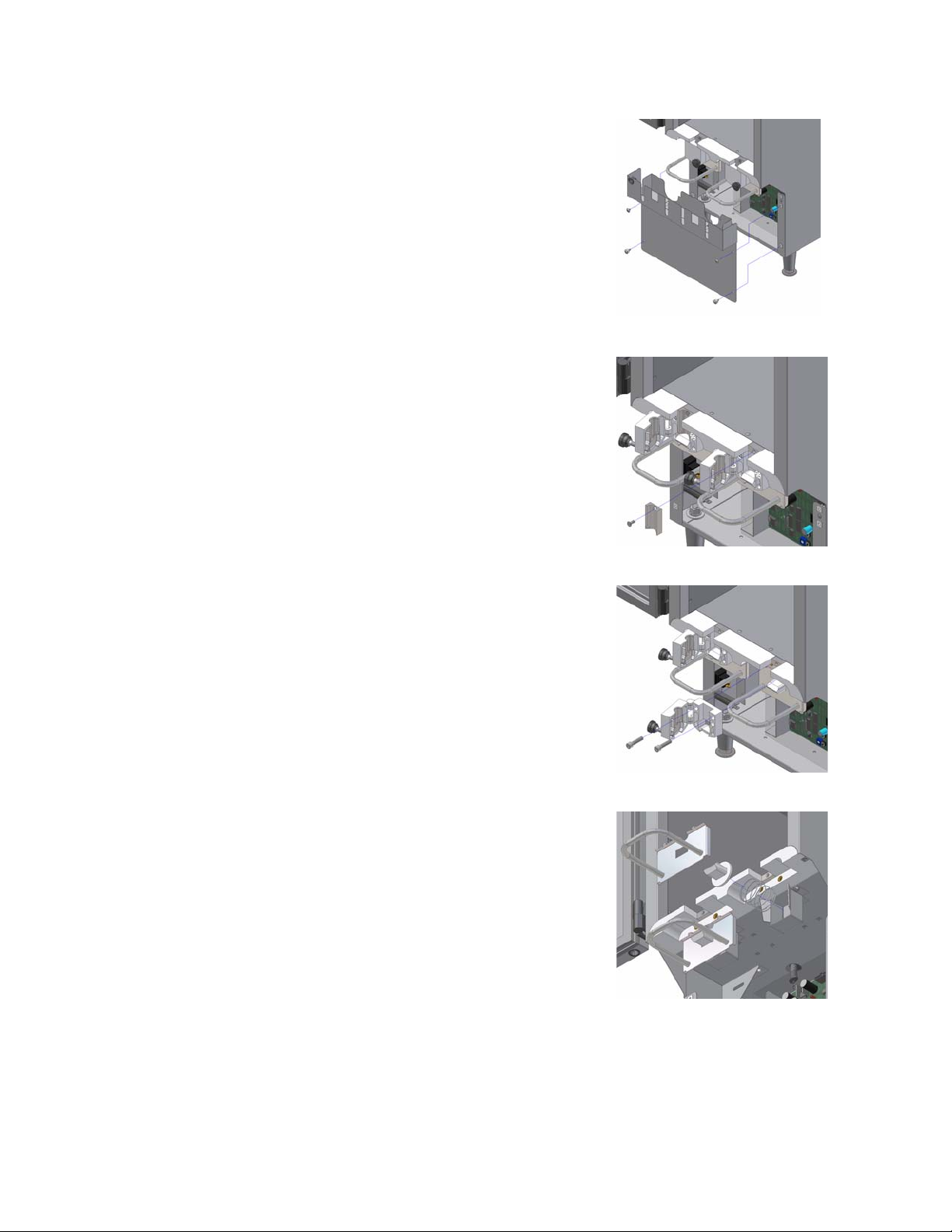
Remove & Replace Compressor Relay
1. Turn the power switch OFF and unplug dispenser.
2. Remove the splash panel – remove the 4 screws.
3. Locate the Electrical Panel holding the Circuit Board.
4. Unscrew and lower the Electrical Panel steel plate and gently turn it around – 4 screws.
5. Locate the Compressor Relay on the back of the Electrical Panel, held in place by 2 screws.
6. Remove the 2 screws and the wires attached. We recommend that you identify the wires for replacement before
you remove them.
7. Replace the Compressor Relay.
8. Reconnect the wires and reinstall Electrical Panel steel plate.
9. Replace the splash panel, using the screws removed in Step 2.
10. Plug in the dispenser.
11. Turn the power switch back ON.
Remove & Replace Transformer
1. Turn the power switch OFF and unplug dispenser.
2. Remove the splash panel – remove the 4 screws.
3. Locate the Electrical Panel holding the Circuit Board.
4. Unscrew and lower the Electrical Panel steel plate and gently turn it around – 4 screws.
5. Locate the Transformer on the back of the Electrical Panel, held in place by 2 screws.
6. Remove the 2 screws and the wires attached. We recommend that you identify the wires and write do wn their
locations before you remove them.
7. Remove the Transformer.
8. Replace with a new Transformer.
9. Reconnect the wires and reinstall Electrical Panel steel plate.
10. Replace the splash panel, using the screws removed in Step 2.
11. Plug in the dispenser.
12. Turn the power switch back ON.
Compressor
Control
Relay
19

Power Switch
ON/OFF
with wires
Circuit Breaker
with wires
Remove & Replace Circuit Breaker
1. Turn the power switch OFF and unplug dispenser.
2. Remove the splash panel – remove the 4 screws.
3. Locate the 3 Amp Circuit Breaker on the lower left side of the dispenser, toward the front.
4. Remove the 2 wires attached to the Circuit Breaker.
5. Pinch together the two tabs that retain the Circuit Breaker and push it out.
6. Replace with a new Circuit Breaker, using the reverse steps.
7. Replace the splash panel, using the screws removed in Step 2.
8. Reconnect the AC power supply by plugging the dispenser in to the wall outlet.
9. Turn the power switch back ON.
Remove & Replace ON/OFF Switch
1. Turn the power switch OFF and unplug dispenser.
2. Remove the splash panel – remove the 4 screws.
3. Locate the ON/OFF switch on the lower left side of the dispenser, toward the front.
4. Remove the 2 wires attached to the ON/OFF Switch.
5. Pinch together the two tabs that retain the ON/OFF Switch and push it out.
6. Replace with a new ON/OFF Switch, using the reverse steps.
7. Replace the splash panel, using the screws removed in Step 2.
8. Reconnect the AC power supply by plugging the dispenser in to the wall outlet.
9. Turn the power switch back ON.
20

Remove & Replace Condenser Fan
1. Turn the power switch OFF and unplug dispenser.
2. Remove the splash panel – remove the 4 screws.
3. Locate the Electrical Panel holding the Circuit Board.
4. Unscrew and lower the Electrical Panel steel plate – 4 screws.
5. Locate the Condenser Fan attached to the bottom of the floor of the refrigerated compartment. It is held in place by
2 bolts and nuts.
6. Locate and cut the two wires attached to the fan and remove it.
7. Splice the wires from the new fan to the existing wires that were cut in Step 5. Use UL-approved crimp connectors
to splice the wires together. Do not use electrical tape.
8. Reinstall the fan and the Electrical Panel steel plate.
9. Replace the splash panel, using the screws removed in Step 2.
10. Reconnect the AC power supply by plugging the dispenser in to the wall outlet
11. Turn the power switch back ON.
Remove Back Panel
1. Turn the dispenser around to access the back panel.
2. Remove the 9 screws holding the back panel.
Replace Electrical Cord
1. Turn the power switch OFF and unplug dispenser.
2. Remove the back panel by removing the 9 screws.
3. Using pliers, depress the plastic wire strain relief grommet where the cord enters the stainless steel body of the
dispenser and turn it to the right.
4. Slide the cord out.
5. Remove the ground wire from the cord and from the grounding post.
6. Cut and splice the live and neutral wires from the AC power cord.
7. Reconnect with appropriate UL-approved crimp connectors. Do not use electrical tape.
8. Replace the strain relief.
9. Replace the back panel, using the screws removed in Step 2.
10. Reconnect the AC power supply by plugging the dispenser in to the wall outlet
11. Turn the power switch back ON.
21

6. CHECKS AND ADJUSTMENTS
AC Outlet for 120 VAC
1. Using a Digital Multi-Meter set to AC (~),
place probes in the slotted sections of the wall outlet.
The Digital Multi-Meter should read 110-120 VAC ± 3 Volts.
If this voltage is 0 Volts AC, this may indicate a tripped
Circuit Breaker in the building’s Electrical panel.
If the voltage is outside the specified range, please
contact a licensed electrician to investigate.
AC 120 VAC input to Transformer
Note: Turn the power OFF until you are ready to check.
1. Locate the Transformer on the back of the Electrical Panel.
You will see 2 wires entering the Transformer.
For location of Transformer, see page 19.
2. Carefully pull back the push-on connectors.
3. Turn the power back ON.
4. With Digital Multi-Meter set to AC (~), place probes on the posts of the Transformer.
Your meter should read 110-120 VAC ± 3 Volts.
5. If that reading is 0 VAC, troubleshoot to find what is interrupting the power supply from the wall plug to the
transformer. Check the plug-in connection at the wall, the power switch, the circuit breaker, the connectors, etc.
AC 24/12 VAC output to PCB from Transformer
Note: Turn the power OFF until you are ready to check.
1. Locate the Transformer on the back of the Electrical
Panel. You will see 3 wires from the
2. Carefully pull back the push-on connectors.
3. Turn the power back ON.
4. With Digital Multi-Meter set to AC Volts (~), place the
probes on the posts of the Transformer.
Your meter should read: (ct = center tap)
Orange (ct) ~ Yellow = 12 VAC ± 1 VAC
Orange (ct) ~ Blue = 12 VAC ± 1 VAC
Yellow ~ Blue = 24 VAC ± 1 VAC
5. If you do not get these voltages, check the input to the
transformer and the Circuit Breaker for trip and/or continuity.
NOTE: The power LED on the Circuit Board may still illuminate,
even with the Circuit Breaker tripped.
Transformer.
22

DC 2.8 Æ 3.8 VDC input of Valve Thermistor
Note: Turn the power OFF until you are ready to check.
1. Remove the splash panel – remove the 4 screws.
2. Locate the Valve Thermistor (Connector J8).
3. Turn the power back ON.
4. Check for +2.8 VDC Æ +3.8 VDC between Pin 1 (IN) and
Pin 2 (Gnd) on (J8) of the ‘TEMP.’ terminal strip located
at the top of the Circuit Board (corresponds to room
temperature 75 °F Æ 14 °F respectively).
5. If these voltages are not measured, replace the Thermistor.
See page 17.
6. You can also check the resistance of this Thermistor – see
below.
7. Replace the splash panel, using the screws removed in Step 2.
Resistance of Valve Thermistor
Note: Turn the power OFF.
1. Disconnect both wires.
2. Check for approximately 10K – 50K ohms
at the two wire leads of the thermistor.
3. If you do not get a similar reading, replace the valve thermistor.
To replace valve thermistor:
5a. Disconnect Thermistor.
If operated with the Thermistor disconnected, the dispenser
goes into a default “ON” time of 6 minutes and
an “OFF” time determined by the temperature adjust
potentiometer located on the Circuit Board (R36).
5b. Replace Thermistor immediately. See page 17.
DC 2.8 Æ 3.8 VDC input of Display Thermistor
Note: Turn the power OFF until you are ready to check.
1. Remove the splash panel – remove the 4 screws.
2. Locate the Display Thermistor connector AD1 (2-pin connector)
on the bottom right side of the Circuit Board.
3. Turn the power back ON.
4. With the Digital Multi-Meter set to DC Volts (---),
check for +2.8 VDC Æ +3.8 VDC (corresponds to room
temperature 75 °F to Æ 14 °F respectively).
5. If these voltages do not fit into this range, replace the Thermistor.
6. You can also check the resistance of this Display Thermistor –
see below.
7. Replace the splash panel, using the screws removed in Step 2.
NOTE: If faulty, the temperature display in the LCD window may be
blank, a high temperature, or unusual characters. If so, replace Thermistor. See page 18.
Resistance of Display Thermistor
Note: Turn the power OFF.
1. Disconnect the wires.
2. Check for approximately 10K – 50K ohms
wire leads of the thermistor. If you do not get a similar
reading, replace the Display Thermistor.
To replace Display Thermistor, see page 18.
NOTE: This is the Thermistor only for the temperature display in
the LCD window on the front door. The dispenser will
operate with this display Thermistor disconnected but a
faulty thermistor should be replaced as soon as possible.
at the two
23

38 VDC output to Compressor Relay
1. Turn Power switch OFF.
2. Remove the splash panel by removing the screws.
3. Locate the R36 Temp Adjust potentiometer on the Circuit
Board and record the setting before making adjustment.
4. Turn R36 Temp Adjust potentiometer to 5:00 o’clock on the
Circuit Board (turn all the way to the right).
5. Turn Power switch back ON.
6. Wait 2½ minutes. The compressor should start.
If not, with the Digital Multi-Meter set to DC Volts,
check for approximately +38 VDC between Pin 1 (+24)
and Pin 5 (REL) on the (J2) terminal strip (red wires).
7. If voltage is okay at these points, then the Circuit Board
is okay.
If voltage is not apparent, change the Circuit Board.
See page 14, 15 for proper setup of temperature.
8. Return the setting to the prior setting recorded in Step 3.
Do not leave the Temp Adj at 5 o’clock – that will freeze dairy product. See page 12 - 13.
9. Replace the splash panel. Using the screws removed in Step 2.
120 VAC input to Compressor Back
Note: Turn the power OFF until you are ready to check.
1. Remove the back panel – remove the 9 Phillips
screws holding it in place.
2. Remove the retaining clip holding the black plastic
cover to the rear of the Compressor.
3. Remove the cover.
4. Gently pull back the connector to the Compressor
without completely removing it.
5. Turn the power back ON to do the check.
6. With the Digital Multi-Meter set to AC Volts (~),
check for 110-120 VAC ± 3 Volts on the bottom two leads.
If you don’t get this reading, check the wall outlet or the
dispenser's wiring harness.
7. Replace the compressor cover.
8. Replace the back panel, using the screws removed in Step 2.
Product Temperature Check
1. It is imperative that your dispenser’s temperature is stabilized for at least 24 hours before attempting an adjustment.
2. Place product or water at 38 °F in a container. Place the container in the refrigerated compartment for 24 hours.
3. Check the temperature of the fluid. Do not rely on the LCD displayed temperature found on the front door.
4. If the fluid is not under 40 degrees, perform the Product Temperature Adjustment on the Circuit Board. See Pages 12
and 13.
24

Displayed Temperature Offset Check
1. It is imperative that your dispenser’s temperature is stabilized for at least 24 hours before attempting an adjustment.
2. Place product or water at 38 °F in a container and place it in the refrigerated compartment for 24 hours.
3. Check the temperature of the fluid.
4. Compare it to the LCD-displayed temperature on the front door.
5. If the fluid is not correct at ± 2 degrees, perform the following:
To Calibrate the Displayed Temperature Offset – AC220 - FP
NOTE: Before making this adjustment, make sure the product has been in the refrigerated compartment of the dispenser
for 24 hours. Then, measure and record the temperature displayed on the dispenser door. Use a high quality,
accurate thermometer to measure and record the actual temperature of the stabilized product. If the displayed
temperature and the actual product temperature do not match, proceed to Step 1.
1. Remove the lower stainless steel splash panel. It is located below the white plastic valve(s) that holds the product
tube(s). It is held in place by 4 screws.
2. Locate the Circuit Board (see diagram below) that has electronic components on it. A red LED light should be ON
indicating power is supplied to the board.
3. Locate the Program Switch (S3) on the lower right corner of the Circuit Board. There is a second RED LED directly to
the right of this switch.
4. Locate the two white or black buttons (S1 and S2) to the left of the Program Switch on the Circuit Board. UP and
DOWN are printed above and below these buttons.
5. Depress and hold both buttons at the same time as you slide the Program Switch (S3) to the down position.
Continue to hold these buttons down until the display in the LCD window on the dispenser door reads MEMORY
CONTENTS.
6. Release both UP (S1) and DOWN (S2) buttons.
NOTE: Press the DOWN (S2) button until TO or Temp Offset is displayed in the LCD window.
The LCD window will show Factory Temperature Offset TO-07 if no previous adjustments have been made.
7. To increase the displayed temperature by 2 degrees: press the UP (S1) button on the Circuit Board.
To decrease the displayed temperature by 2 degrees: press the DOWN (S2) Size button on the Circuit Board.
Each increase or decrease changes the displayed temperature by 2 °F.
Repeat presses until the required number of 2 °F incremental increases have been entered. E.g. if the display and
product temperature numbers vary by 4 degrees, press the button twice.
8. Slide the Program Switch (S3) to the Up position and check the display temperature on the dispenser door.
9. Allow the dispenser to operate for 20 to 30 minutes to allow the product temperature to stabilize.
Check the temperature reading to verify temperature calibration is correct.
If it is not correct, repeat steps 5 – 8 above.
10. Replace the front splash panel/valve cover using the screws removed in Step 1.
AC xxx
Rev x
Mm/yy
Temp
Adjust
UP “S1”
PROGRAM “S3”
Program Mode
Red LED
DOWN “S2”
25

Product Temperature Adjustment
NOTE: Each SureShot Dispensing Systems® dispenser is pre-set at our factory to meet your operating standards.
These settings should not require adjustment.
The temperature in the refrigerated product compartment is set at our factory for normal use in the North
American food service industry. The temperature is set to maintain the product within the range of 35 ºF to 40 ºF
(1.6 ºC to 4.4 ºC). The temperature is controlled by an adjustable thermostat. The adjustment pot for this
thermostat is located at the middle of the right side of the circuit board. (See below)
1. Remove the 4 screws that secure the front splash panel/valve cover in place and carefully remove the front splash
panel/valve cover. It is located below the white plastic valves that hold the product tubes. It is held in place by 4
screws (+).
2. When this cover is removed, locate the Circuit Board that has electronic components on it. A red LED light should
be (ON) indicating that there is power supplied to the board.
3. Locate the Temp. Adj. (R36 - Temperature adjustment) Pot, which is on the middle bottom of the circuit board. It is
a blue plastic square, approximately ½” square. It has a white circular center with a slot.
4. From the factory, this Temp. Adj. slot adjustment would have been set vertical (at 12 and 6 o’clock if you were to
compare it to hands on a clock).
5. Follow the instructions on page 13 for adjustments, depending on whether your dispenser i s running too cold or too
warm.
Temperature Adjust R 36 Program Switch
26

ELECTRICAL SYSTEM:
Flip-up Lid
Door Hinge – Lift
door to separate
Power
Circuit
Breaker
Not all dispenser models have a Power Indicator LED on the front door.
LCD
Display
Power
Indicator
Valve
Circuit
Board
Catch
Tray
Electrical System
27

WIRING DIAGRAM:
Breaker
CB1
Yel
Blu
Org
Yel
TRANS1
Brn
EMI1
Brn
Blu
Blu
TH2
PCB1
CAS E S WITCHES
GND123
TEMP
IN GND
AC IN
CT2424
Tee Thermistor
GND
+24V
SOL1
SOLENOIDS
SOL2
SOL3
REL
TH1
Box Thermistor
AD1
Blk
Fan
Blk
Blk
Switch
P1
Blk
Blk
Wht
L
N
Gnd
SW1
Blu
Yel
Org
Red
BlkWht
C5
Red
Com
NO
Org
Yel
M2
S3
N
Cap
Gnd
Org
L
Compresso r
Grn
RL1
C1
Relay
Run Capacitor
120V
1 Phase
28

GENERAL ASSEMBLY: (Parts list follows on page30)
29

PARTS LIST:
ITEM QUANTITY PART NUMBER DESCRIPTION
2 1 A-04-073-13 Catch Tray Assembly (220 Counter)
3 1 A-04-003-10 Front Panel Assembly (220 SS) with grommet
5 1 A-05-004-2 Side Console Power Supply Assembly
6 2 A-07-009 Valve Door Final Assembly (.900-MOD SS)
7 1 A-09-008-4 Door Assembly – Front (20L FP-SS wo-Display)
8 2 A-14-012 Dispense Handle Assembly (.900 SS)
9 2 A-18-003 2.5 US Gal Tank Assembly
10 1 A-19-012 Decal Kit AC220-FP-SS-01
11 1 A-22-019-3 Electrical Panel Installation Side Console
12 1 E-99-019 Splash Shield – Side Console
13 4 F-01-001 3/8-16 UNC-2B Hex Nut
14 4 F-03-002 3/8 FW
15 13 F-04-002 8-18 x 3/8 SS P-TH TS
16 8 F-04-003 8-18 x 5/16 S-HWT TS (Type B)
17 2 F-05-005 4-40 UNC-2A x 3/16 P-PH MS
18 4 F-05-013 1_4-20 UNC-2A x 1 SS P-F-MS
19 4 F-06-001-1 Rivet – SS Blind 1/8 x .265
20 1 F-12-004 Wire Grommet – 3/8
21 4 F-14-014 Leg – 4in. ADJ (Metal)
22 1 F-16-003 Beaded Tie – 6
23 2 F-99-001 Product Solenoid Spring
24 4 F-99-008 Rubber Foot - .750 (Grey)
25 1 M-01-026 Back Panel (20L)
26 2 M-02-109 Dispense Handle Spring Cup
29 1 M-06-189 Ref Control Overlay
30 2 P-01-013 Plunger Tip (.900x850-2X45-Molded)
1 A-12-022-2 Circuit Board Assembly – Ref Control
1 A-12-023-2 Circuit Board Assembly – Ref Connector
1 A-12-013 Circuit Board – self-serve B-16
1 E-08-011 ON-OFF Switch – Recessed
1 E-13-019 Power Cord – Wire Harness
1 E-14-002 1 Amp Circuit Breaker
1 E-21-002 Fan
1 R-02-001 Condenser
1 A-99-005 Compressor Assembly
30

TROUBLESHOOTING PROBLEMS – AC220-FP AC320-FP
PROBLEM ACTION
No power at the plug
Dispenser will not turn on 1. Make sure the power cord is plugged in to an active power source.
Dispenser is not level 1. Check to make sure all four legs at the bottom corners of the dispenser are in
Valve is sticky 1. A sticky valve is usually caused by product build-up on the valve. The problem is
Dispenser will not dispense
product
The dispenser is not dispensing
the proper amount of product
1. Have a qualified person check the fuse box or circuit breaker to restore power to
the circuit.
2. Check AC outlet to make sure it is 120 VAC.
3. Try another working appliance in the outlet to confirm that the problem is in the
outlet.
2. Check the ON/OFF switch (see page 3) on the left side of the dispenser to make
sure it is ON.
3. Check to make sure the circuit breaker on the left side of the dispenser has not
tripped out. If it has, turn the power switch OFF, reset the circuit breaker by
gently pushing it in once to reset it – push in at the top of the breaker until no
white is showing. Then, turn the power back ON.
place.
2. Tighten any legs that are loose.
3. Make sure the legs are not bent.
4. Replace any bent or missing legs. Replacement legs may be obtained by
contacting SureShot Dispensing Systems® Technical Assista nce Center at
1-888-777-9990 or 1-902-865-9602.
5. For dispensers with adjustable legs, adjust legs to level dispenser. Use a bubble
level to ensure accuracy.
corrected by cleaning the valve. See Instructions on page 10.
2. If this doesn't correct the problem, call the SureShot Dispensing Systems®
Technical Assistance Center at 1-888-777-9990 or 1-902-865-9602.
1. Make sure the power cord is plugged in to an active power source.
2. Make sure there is product – milk, cream, etc – in the product tank.
3. Make sure the product dispensing tube from the product tank is clear of blockage
and is properly aligned in the valve with no twists or kinks and is not pinched off.
4. Make sure the valve door is closed.
5. Check the valve area and the valves to make sure they are clean. NOTE: most
problems are caused by dirty, sticky valves. To clean, see page 10.
6. Check the temperature inside the refrigerated product compartment, to make sure
it is within the temperature range of 35 ºF. to 40 ºF. (1.6 ºC to 4.4 ºC.) If the
dispenser is running cold, it could form ice which interferes with the flow of
product.
If a temperature adjustment is required, follow the instructions on page 13. If
further assistance is required, contact the SureShot Dispensing Systems®
Technical Assistance Center at 1-888-777-9990 or 1-902-865-9602.
7. Check to ensure that the green power indicator light (the green LED on the front
door of the dispenser OR on the Circuit Board) is on.
8. If the power indicator light on the door or on the Circuit Board is not on, check the
circuit breaker.
To check the Circuit Breaker:
- Confirm that the Circuit Breaker on the lower left side of the dispenser has not
tripped out. If it has, turn OFF the dispenser, re-set the Circuit Breaker by
gently pushing it in once to reset it – push in at the top of the breaker until no
white is showing. Then, turn the power back ON.
9. If there still is no product dispensed, contact the SureShot Dispensing Systems®
Technical Assistance Center at 1-888-777-9990 or 1-902-865-9602.
1. Wrong dairy product is being dispensed – for example, skim instead of cream.
2. Make sure that the product delivery tube is inserted in the valve correctly since
incorrect placement can affect product delivery. See page 7.
3. Check to ensure that valve and valve area are clean.
4. Make sure the valve door is not being opened before the product tank is empty.
31

Valve door is broken This indicates the door hinge is broken. The hinge is in two parts: hooks, pins.
1. Hooks: If either or both of the plastic “hooked” areas of the hinge are missing, the
door section valve assembly is broken and must be replaced.
Contact SureShot Dispensing Systems® Technical Assistance Cent er at
1-888-777-9990 or 1-902-865-9602 for replacements.
2. Pins: If either or both plastic “pins” are missing from the hinge area, the body
section of the valve is broken and must be replaced. Contact your head
office/warehouse or SureShot Dispensing Systems® Technical Assistance Center
at 1-888-777-9990 or 1-902-865-9602 for replacements.
Dispenser is unusually warm on
the exterior
Dispenser is unusually warm on
the interior
Dispenser is too cold in the
interior
1. Check to ensure the vents at the top back of the dispenser are not blocked.
2. Check to make sure the dispenser is not too close to a heat-generating machine,
such as a coffeemaker. Allow a minimum 1-inch airspace between machines at
all times.
3. Check to ensure that the dispenser is level on the countertop at all times.
4. Check to ensure the condenser is not dirty.
Remove the back panel to examine the condenser. If it is dusty or dirty, use
a vacuum to clean it.
5. Check to ensure the fan is operating. Remove the front splash panel and
observe the fan on the right side of the dispenser, in front of the compressor and
behind the circuit board. (See page 12) Do a visual inspection only.
Be careful not to injure fingers by sticking them in the fan.
If the fan is not running, call the SureShot Dispensing Systems® Technical
Assistance Center at 1-888-777-9990 or 1-902-865-9602.
1. Check the product temperature, to ensure that the product is properly cooled to
approximately 38 ºF or 3.3 ºC before it is loaded into the dispenser.
2. Check to ensure the vents at the top back of the dispenser are not blocked.
3. Check to make sure the dispenser is not too close to a heat-generating machine,
such as a coffeemaker. Allow a minimum 1-inch (2.5 cm) airspace between
machines.
4. Check to ensure that the dispenser is level on the countertop at all times.
5. Check to ensure the condenser is not dirty.
Remove the back panel to examine the condenser. If it is dusty or dirty, use
a vacuum to clean it.
6. The dispenser may be on defrost cycle. The defrost cycle time is 22 minutes in
duration. If, after 22 minutes have passed, the dispenser is not cool, re-set the
defrost cycle by turning OFF the dispenser, waiting 10 seconds, and turning it
back ON again. It should become cold after approximately 12 minutes.
7. Check to ensure the fan is operating. Remove the front panel and observe the
fan on the right side of the dispenser, in front of the compressor and behind the
circuit board. (See page 12) Do a visual inspection only.
Be careful not to injure fingers by sticking them in the fan.
If the fan is not running, call the SureShot Dispensing Systems® Technical
Assistance Center at 1-888-777-9990 or 1-902-865-9602.
8. Check the display thermistor. If faulty, it can affect the temperature. See page 23.
9. If the problem is still not solved, call the SureShot Dispensing Systems®
Technical Assistance Center at 1-888-777-9990 or 1-902-865-9602.
1. Check product temperature.
2. If a temperature adjustment is required, follow instructions on page 13.
3. Check valve thermistor to determine if it is working properly. See page 23.
If valve thermistor needs replacement, see page 17.
4. Check the display thermistor. If faulty, it can affect the temperature. See page 23.
5. If further assistance is required, contact the SureShot Dispensing Systems®
Technical Assistance Center at 1-888-777-9990 or 1-902-865-9602.
Frost build up in the refrigeration
compartment
1. Check the temperature inside the refrigerated product compartment, to make sure
it is within the temperature range of 35 ºF to 40 ºF (1.6 ºC to 4.4 ºC). If the
dispenser is running cold, it could form more ice than normal.
2 If the dispenser has accumulated ice or frost at the top of the compartment, it is
best to remove it during a defrost cycle, which runs automatically and will be
indicated on the LCD display panel. Forming ice does not necessarily mean the
32

temperature of the product is too cold.
3. Ice may be removed during a product change:
a Turn OFF the dispenser.
b Open the dispenser door and leave it open for about 15 minutes to allow the
ice to soften.
c Remove the ice by hand.
d Wipe the compartment down and dry thoroughly.
e Turn the dispenser back ON.
4. If a temperature adjustment is required, follow the instructions on page 13.
If further assistance is required, contact the SureShot Dispensing Systems®
Technical Assistance Center at 1-888-777-9990 or 1-902-865-9602.
Dispenser is leaking product 1. Make sure the valve door is closed securely and its knob-screw is tightened
properly.
2. Make sure the product dispensing tube is properly aligned in the centre of the
delivery valve.
3. Check the tube for cracks or disfiguration. If the tube is cracked or disfigured,
replace it. See page 7.
4. Check the valve to make sure that it is not dirty.
If required, clean the valve following instructions on page 10.
5. Check to make sure the valve hinges are not broken.
6. Check to ensure that the plunger and valve assembly are correct. Ensure that the
spring is present and is properly seated in the spring retainer.
LCD Display on the front door
does not come on
Temperature display is blank or
an extreme temperature or
unusual characters
For service, if you are within the Warranty Period for your dispenser, please contact:
SureShot Dispensing Systems® Technical Assistance Center
If your Warranty has expired, contact your Service Technician.
NOTE: The Serial Number and Model Number of your Dispenser are located on the Product Identification Label on the
left side of the Dispenser. Please refer to these numbers when contacting the Technical Assistance Center. These
numbers are crucial to helping us provide prompt and effective service. This will save you time.
Check to ensure that the power indicator light (the green LED on the front door of the
dispenser OR the red LED on the Circuit Board) is on.
If the power indicator light is lit and the LCD Display is not lit, call SureShot
Dispensing Systems® Technical Assistance Center at 1-888-777-9990 or 1 -9 02-8659602 to replace the LCD Display.
If both the power indicator light and the LCD Display are not lit, check the power
supply to the dispenser - the circuit breaker may have tripped out and needs to be
reset.
To Reset the circuit breaker:
1. Turn the power switch OFF.
2. Check the circuit breaker:
- Locate the Circuit Breaker on the lower left side of the dispenser.
- Gently push the Circuit Breaker in once to reset it – push in at the top of the
breaker until no white is showing. Then, turn the power back ON.
3. Turn the power switch ON.
4. If the LCD Display does not come on now, call the SureShot Dispensing
Systems® Technical Assistance Center at 1-888-777-9990 or 1-902-865-9602.
1. Check the display thermistor. A faulty display thermistor can affect the
temperature. To check, See page 23.
A.C. Dispensing Equipment, Inc.
1-888-777-9990 or 1-902-865-9602
www.sureshotdispensing.com
E-mail: service@sureshotdispensing.com
33

NOTES:
34

NORTH AMERICAN WARRANTY
All dispensing equipment manufactured by A.C. Dispensing Equipment Inc. is warranted against defects in materials and
workmanship for a period of one (1) year from the date of purchase.
A. C. Dispensing Equipment Inc.'s obligation under this warranty is limited to the repair of defects as outlined by an A. C.
Dispensing Equipment Inc. factory-authorized service agency or one of its sub-service agencies.
This Warranty does not apply to installation or problems because of installation. This Warranty does not apply to normal
preventative maintenance, maintenance or adjustment.
THIS WARRANTY WILL BE NULL AND VOID IF THE WARRANTY REGISTRATION CARD IS NOT RETURNED TO A. C.
DISPENSING EQUIPMENT INC. WITHIN 60 DAYS OF PURCHASE.
This warranty is subject to the following conditions:
• This warranty applies to the original owner only and is not assignable.
• Only pre-authorized service agencies directed by A.C. Dispensing Equipment Inc. are to be utilized.
• Should any product fail to function in its intended man ner under normal use within the limits defined in this warranty, at the
option of A. C. Dispensing Equipment Inc. such product will be repaired or replaced b y A.C. Dispensing Equipment Inc. or its
Authorized Service Agency. A. C. Dispensing Equipment Inc. will be responsi ble only for charges incurred or service performed by
its Authorized Service Agencies. The use of other than A. C. Dispensing Equipment Inc. Authorized Service Agencies will void this
warranty and A. C. Dispensing Equipment Inc. will not be responsible for such work or any charges associated with such work.
The closest A. C. Dispensing Equipment Inc. Authorized Service Agency must be used.
TIME PERIOD:
One year on parts and labour, effective from the date of purchase. The Authorized Service Agency may, at its option, require
proof of purchase. Parts replaced under this Warranty are warranted for the unexpired portion of the origin al product warranty
only.
A service consultant is available to assist you during our norma l business hours. All s ervice-related issues will be addressed by a
return telephone call the next business day.
WARRANTY PROCEDURE:
1. Secure the model and serial number from the data tag on the lower left side of the dispenser.
2. Call the number provided on the service label on the dispenser.
3. Our technical support staff will discuss the issue with you and, if necessary, dispatch a technician to your locati on for repairs.
If after-hours or emergency service is required, A.C. Dispensing Equipment Inc. will not be responsible for any additional
charges.
4. To order parts, call the service center and the appropriate parts will be sent to your location or that of the servicing agency.
The following conditions are not covered by this Warranty:
• Equipment failure related to improper installation, improper utility connection or supply, and problems due to ventilation.
• Equipment that has not been properly maintained, calibration of controls, adjustments, damage from improper clea ning,
and water damage to controls.
• Equipment that has not been used in an appropriate manner, or has been subject to misuse or misapplication, neglect,
abuse, accident, alteration, negligence, damage during transit, delivery or installation, fire, flood, riot, or act of God.
• Equipment on which the model number or serial number has been removed or altered.
If the equipment has been changed, altered, modified or repaired b y other than a qualified service technician during
or after the warranty period, then the manufacturer shall not be liable for any damages to any person or to an y propert y, which
may result from the use of the equipment thereafter.
This Warranty does not cover services performed at overtime or premium labour rates. Should service be required at
times which normally involve overtime or premium labour rate s, the owner shall be charg ed for the difference bet ween normal
service rates and such premium rates. A. C. Dispensing E quipment Inc. does not assume any liabilit y for extended dela ys in
replacing or repairing any items beyond its control.
In all cases, the use of other than A. C. Dispensing Equipment Inc. aut horized OEM replacement parts will void this
Warranty.
This equipment in intended for commercial use only. Warranty is void if equipm ent is installe d in other than commerci al
applications.
THE FOREGOING WARRANTY IS IN LIEU OF ANY AND ALL OTHER WARRANTIES EXPRESSED OR IMPLIED,
INCLUDING ANY IMPLIED WARRANTY OF MERCHANTABILITY OR FITNESS AND CONSTITUTES THE ENTIRE
LIABILITY OF A. C. DISPENSING EQUIPMENT INC. IN NO EVENT DOES THE LIMITED WARRANTY EXTEND BEYOND
THE TERMS STATED HEREIN.
5/8/2007 B4C 4H2
This unit is covered by a 1 year on-site warranty, unless otherwise specified.
24-hour Toll-Free Service is available at 1-888-777-9990 or 1-902-865-9602
A.C. Dispensing Equipment Inc.
100 Dispensing Way
Sackville
Nova Scotia, Canada
35

NOTES:
36
 Loading...