

Page 1
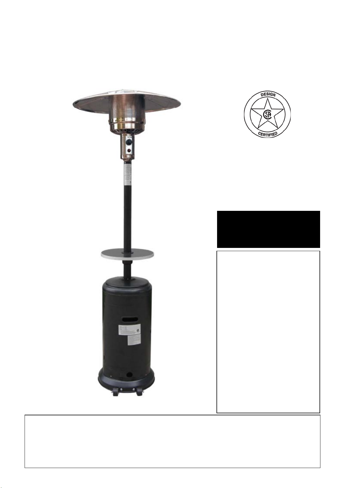
Home Garden
USE AND CARE MANUAL
For Model T87PHLP
Stop! Missing a part? DO
NOT RETURN PRODUCT
TO STORE
FOR YOUR SAFETY:
1. Read this Manual before
attempting to assemble or
operate your patio heater.
2. Follow safety instructions.
3. Check for leaks according
to the directions in this
Manual before operating
your patio heater, even if
purchasing an assembled
patio heater.
4. Ke ep th is Man ual fo r
future reference.
5. Contact 1-800-229-5647
should you need assembly
assist ance or have any
questions.
The store where you made the purchase does not stock
parts for this item. If you need parts, whether they are
missing or damaged, please call Customer Service at
Call us between 8:00 AM and 5:00 PM Eastern time, Monday through Friday
or email us at saleshelp@sureheat.com
1-800-229-5647
Page 2

Table of Contents
General Safety Instructions...............................................................................
Components & Hardware..................................................................................
Additional Requirements..................................................................................
Assembly Process
Step 1 – Attach Wheel Assembly to Base.........................................................
Step 2 –Attach Bucket to Base.........................................................................
Step 3 –Attach Support Brackets to Base.........................................................
Step 4 –Attach Post to Support Brackets.........................................................
Step 5 – Tabletop Installation............................................................................
Step 6 – Attach Reection Studs to Screen Cover............................................
Step 7 – Attach Head Assembly to Post...........................................................
3-5
6-7
7
8
8
9
9
10
11
11
Step 8 – Install Reector...................................................................................
Step 9 – Attach Reector Assembly to Studs...................................................
Step 10– Connect hose & Regulator to Cylinder..............................................
Gas Requirement.............................................................................................
Pre-Operation Leak Testing..............................................................................
Operation..........................................................................................................
Care & Maintenance.........................................................................................
Troubleshooting................................................................................................
Warranty...........................................................................................................
12-13
14
15
16
17
18-19
20
21
22
2
Page 3
General Safety Instructions
IMPORTANT SAFETY INFORMATION
-
This manual contains important information about the assembly, operation and maintenance
of this patio heater. General safety information is presented in these fi rst few pages and is
also located throughout the manual.
- Keep this manual for future reference and to educate new users of this product. This
manual should be read in conjunction with the labeling on the product.
- Safety precautions are essential when any mechanical or propane fueled equipment is
involved. These precautions are necessary when using, storing, and servicing. Using this
equipment with the respect and caution demanded will reduce the possibilities of personal
injury or property damage.
- The following symbols shown below are used extensively throughout this manual. Always
heed these precautions, as they are essential when using any mechanical or fueled
equipment.
RECOGNIZE SAFETY SYMBOLS, WORDS AND LABELS
WARNING
death or serious injury.
NOTE
proper operation of your heater.
DANGER
▲!
If you smell gas:
1. Shut off gas to the appliance
2. Extinguish any open fl ame
3. Open lid
4. If odor continues, keep away from the appliance and immediately call your gas supplier or
your fi re department.
WARNING
▲!
indicates a potentially hazardous situation which, if not avoided, could result in
indicates an important piece of information that needs to be observed to ensure the
1. Do not store or use gasoline or other fl ammable liquids or vapors in the vicinity of this or
any other appliance.
2. An LP cylinder not connected for use shall not be stored in the vicinity of this or any other
appliance.
INSTALLER: Please retain these instructions with the owner so
that they may maintain them for future reference.
3
Page 4

General Safety Instructions
!
DANGER
▲
DANGER indicates you can be killed or
seriously injured if you don't immediately follow
instructions.
!
WARNING
▲
WARNING indicates you can be killed or seriously
injured if you don't follow instructions.
!
CAUTION
▲
CAUTION indicates an imminently hazardous
situation which, if not avoided, may result in minor
or moderate personal injury, or property damage.
!
WARNING
▲
Improper installation, adjustment, alteration,
service or maintenance can cause injury or
property damage. Read the instructions thoroughly
before installing or servicing this equipment.
!
DANGER
▲
EXPLOSION - FIRE HAZARD
- Keep solid combustible materials, such as
building materials and paper or cardboard, a safe
distance away from the heater as recommended by
the instructions.
- Provide adequate clearances around air openings
into the combustion chamber.
- Never use the heater in spaces which may contain
volatile or airborne combustibles, or products such
as gasoline, solvents, paint thinner, dust particles
or unknown chemicals.
- During operation, this product can be a source
of ignition. Keep heater area clear and free from
combustible materials, such as gasoline, paint
thinner, cleaning solvents and other flammable
vapors and liquids. Do not use heater in areas with
high dust content. Minimum heater clearances
from combustible materials: three (3) feet from the
sides & two (2) feet from the top.
FOR YOUR SAFETY
DO NOT store or use gasoline or other fl ammable
vapors and liquids in the vicinity of this or any
other appliance.
An LP cylinder not connected for use shall not be
stored in the vicinity of this or any other appliance.
!
CAUTION
▲
SERVICE SAFTY
- Keep all connections and fittings clean. Make
sure propane cylinder valve outlet is clean.
Inspect hose before use. Replace if there is
evidence of abrasion or wear.
- During set up, check all connections and fi ttings
for leaks using soapy water. Never use a fl ame.
- Use as a heating appliance only. Never alter in
any way or use with any device.
- Check entire hose at least annually.
FOR OUTDOOR USE ONLY
!
WARNING
▲
- We cannot foresee every use which may be made
with our heaters.
- Check with your local fi re safety authority if you
have questions about heater use.
Other standards govern the use of fuel gases and
heat producing products for specifi c uses.
- Your local authorities can advise you about these
standards.
- If no local codes exist, follow National Fuel
Gas Code, ANSI Z223.1. In Canada, installation
must conform to local codes. If no local codes
exist, follow the current National Standards of
CANADA CAN/CGA-B 149.2.
4
Page 5

General Safety Instructions
!
DANGER
▲
CARBON MONOXIDE HAZARD
- This heater is a combustion appliance. All
combustion appliances produce carbon monoxide
(CO) during the combustion process. This product
is designed to produce extremely minute, nonhazardous amounts of CO if used and maintained
in accordance with all warnings and instructions.
Do not block air flow into or out of the heater.
Carbon monoxide (CO) poisoning produces flulike symptoms, watery eyes, headaches, dizziness,
fatigue and possibly death. You can't see it and
you can't smell it. It's an invisible killer. If these
symptoms are present during operation of this
product get fresh air immediately!
- For outdoor use only.
- Never use inside house, or other unventilated or
enclosed areas.
- This heater consumes air (oxygen). Do not
use in unventilated or enclosed areas to avoid
endangering your life.
!
DANGER
▲
EXPLOSION - FIRE HAZARD
- Never store propane near high heat, open ames,
pilot lights, direct sunlight, other ignition souces or
where temperatures exceed 120 (49 ).
Propane vapors are heavier than air and can
accumulate in low places. If you smell gas, leave
the area immediately.
- Never install or remove propane cylinder while
heater is lit, if pilot light is lit, or ignition source
and heater are hot to the touch.
- This hea t er is re d ho t du r in g us e an d can
ignite flammables too close to the burner. Keep
ammables at least 2 feet from sides & 3 feet from
top. Keep gasoline and other flammable liquids
and vapors well away from heater.
- The propane cylinder must always be stored
outdoors in a well ventilated space. Never store
propane cylinder in an enclosed area (House,
garage, etc.). If heater is to be stored indoors,
disconnect the propane cylinder for outdoor
storage.
!
WARNING
▲
- This product is fueled by propane gas. Propane
gas is invisible, odorless, and flammable. An
odorant is normally added to help detect leaks
and can be described as a "rotten egg" smell. The
odorant can fade over time so leaking gas is not
always detectable by smell alone.
- Propane gas is heaver than air and leaking
propane will sink to the lowest level possible.
It can ignite from matches, lighters, sparks or
open flames of any kind many feet away from
the original leak. Use only propane gas set up for
vapor withdrawal.
- P ropa ne g as sho uld be sto red or u se d in
compliance with local ordinances and codes or
with ANSI/NFPA 58. Turn off propane when not in
use.
FOR YOUR SAFETY
If you smell gas:
1. Shut off gas to the appliance.
2. Extinguish open ame.
3. If odor continues, immediately call your gas
supplier and local Fire Dept.
!
WARNING
▲
BURN HAZARD
Never leave heater unattended when hot or in use,
Keep out of reach of children.
!
DANGER
▲
Failure to comp ly with th e pre c aut i ons and
instructions provided with this heater can result
in death, serious bodily injury and property loss
or damage from hazards of fire, explosion, burn,
asphyxiation, and/or carbon monoxide poisoning.
Only persons who can understand and follow the
instructions should use or service this heater.
!
WARNING
▲
California Proposition 65
Combustion by-products produced when
using this product contain chemicals known
to the State of California to cause cancer,
birth defects, and other reproductive harm.
5
Page 6
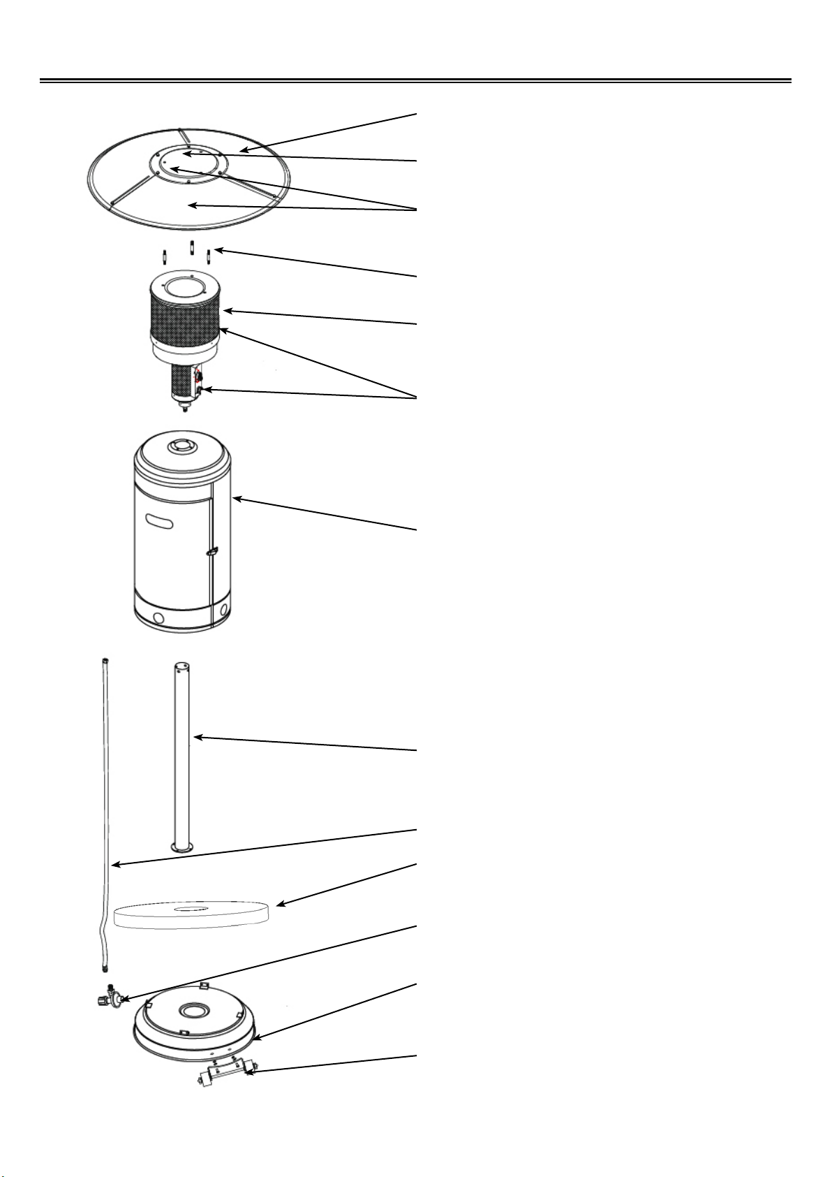
Components & Hardware
1
2
3
4
5
6
Reector Panel (3)
Reector Plate
Reector Assembly
Reector Stud (3)
Heater Burner Screen
Heater Assembly
7
8
9
10
11
Cylinder Housing
Post
Gas Hoseless Regulator
Tabletop
Regulator
6
12
13
Base
Wheel
Page 7
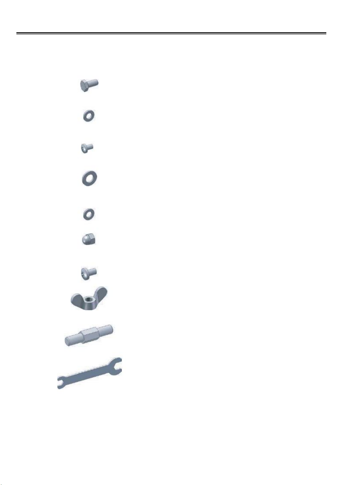
Hardware
Picture Qty Description
Components & Hardware
Used in
Step(s)
4
4
4
Total 9
9
9
Small Bolt
Small Fla t
Washer
Small Screw
Large Flat
Washer
Me di u m F la t
Washer
Cap Nut
4
4
3
6 & 9
8
8
9
3
3
1
Small screw
Wing Nut
Reector Stud
Wrench
8
9
6
1 / 3 / 4 /
7 / 8
Additional Requirements
The following items are not included, but are necessary for the proper assembly of your heater. DO
NOT attempt to assemble without proper tools.
- Phillips screwdriver w/ medium blade.
- Adjustable opening wrench.
- Leakage Detection Solution (Instructions on how to make solution are included on page 15)
Note: You must follow all steps to properly assemble heater.
7
Page 8

Assembly Process
Step 1 - Attach Wheel Assembly to Base
Wheel Assembly
2 Medium bolts /2 Large Flange Nuts
Line up holes in Wheel Bracket with corresponding holes in base. Insert 2 Medium bolts through
holes and nger tighten the 2 Large Flange Nuts.
Be sure that the Wheel Assembly is parallel to the base, and fully tighten bolts.
Step 2- Attach Bucket to Base
Bucket
4 Large Screws / 4 Large Nuts
Slip 4 Large Screws though holes of Base.
Lay Bucket inside of Base and screw on large nut. Tighten with Phillips screwdriver.
To improve stability, the bucket should be lled with sand.
8
Page 9

Assembly Process
Step 3- Attach Cylinder Housing to Base
Attach Cylinder Housing loosely to Base with four Small Screws.
Step 4- Attach Post to Cylinder Housing top
Open the door, put post through the hole on the top of Cylinder Housing.
Attach post to Cylinder Housing using four Small Bolts, Nuts and Small Flat Washers.
9
Page 10

Assembly Process
Step 5 - Tabletop Installation
Place the Plastic nut & Fastening piece through the post in order. Put the Tabletop through the post
as shown.
Place the plastic connecting piece through the post as shown.
Slide the Fastening piece through the hole on the Tabletop. Hold the tabletop in position and tighten
the Fastening piece to the Plastic connecting piece in a counter-clockwise direction. Loosen the
Plastic nut, adjust the Tabletop to the desired height, and then tighten the plastic nut to secure the
tabletop in position.
10
Page 11

Assembly Process
Step 6 - Attach Reector Studs to Screen Cover
Insert 3 Reector Studs & 3 large Flat Washers.
Tighten studs securely.
3 Reector Studs
Step 7 - Attach Head Assembly to Post
4 Small Bolts Head Assembly
3 Large Flat Washers
Remove 4 small bolts from the top of the Head
Assembly .
Insert hose end into the top of the post and then
rest the burner head assembly onto the post
making sure that the control knob is positioned
above the lighting instructions on the post.
Attach Head Assembly to post, and loosely install
four small bolts.Tighten bolts securely.
11
Page 12

Step 8 - Install Reector
!
WARNING
▲
Remove protective lm before assembly
Assembly Process
Note: It is necessary for proper alignment of reflector section to loosely install all of the screws
for assembly prior to tightening. Once all of the screws have been loosely installed, tighten with a
wrench.
9 Small Screws
Slide two Reector Panels together.
9 Medium Flat Washers
Insert one Small Screw.
9 Cap Nuts
12
Page 13

Assembly Process
Slide one Small Flat Washer over threaded end of screw and loosely screw on Cap Nut. Repeat
procedure to complete the assembly of all three Reector Panel sections.
Slide Reector Plate onto Reector Panels.
Insert one Small Screw.
Once all screws have been loosely installed, tighten all screws with a wrench.
Slide one small Flat Washer over threaded end
of screw and loosely screw on Cap Nut. Repeat
procedure to install the remaining screws.
13
Page 14

Assembly Process
Step 9 - Attach Reector Assembly to Studs
Support Heater.
Slide 3 Large Flat Washers over threaded end of Studs.
6 Large Flat Washers
Install Reector Assembly onto three (3) studs.
Install large at washers on studs and securely tighten wing nuts. Make sure not to overtighten the
wing nuts.
3 Wing Nuts
14
Page 15

Assembly Process
Step 9 - Connect Hose & Regulator to Cylinder
Specifi cations
- You must provide propane gas and propane cylinder. Use a
standard 20 lb. Propane cylinder only.
- Use this heater only with a propane vapor withdrawal supply
system. See Chapter 5 of the Standard for Storage and
Handling of Liquefi ed Petroleum Gas, ANSI/NFPA 58. Your local
library or fi re department should have this book.
- The minimum permissible gas supply pressure of 10 W.C. is
required for purpose of input adjustment.
- The installation must conform with local codes, or in absence of
local codes, with National Fuel Gas Code, ANSI Z223.1.
- The minimum hourly output of 17000 Btu is the required rating of
a heater operating at ratings less than full input rating.
- The pressure regulator and hose assembly supplied with the
appliance must be used.
- A dented, rusted or damaged propane cylinder may be
hazardous and should be checked by your cylinder supplier.
Never use a propane cylinder with a damaged valve connection.
- The propane cylinder must be constructed and marked in
accordance with the specifi cation for LP gas cylinders of the U.S.
Department of Transportation (DOT).
- Never connect an unregulated propane cylinder to the heater.
Standard 20lb. tank
Screw regulator onto gas hose. Do not cross-thread.
Attach regulator to cylinder.
Complete attachment.
Tighten securely.
Install cylinder.
15
Page 16

Gas Requirements
L.P. GAS INSTALLATION
Gas Heaters that are set to operate with L.P. gas come with a high capacity hose and regulator assembly.
(Note: Only use the pressure regulator and hose assembly supplied with the heater or a replacement
pressure regulator and hose assemblies ).
20 lb. L.P. cylinder. L.P. Cylinders are not included with the heater. L.P. Cylinders they can be purchased
separately at an independent dealer.
This assembly is designed to connect directly to a standard
Ta nk
connection
Upright Tank
Orientation
LP hose/
regulator
supplied
(Type 1
connector)
Regulator Inlet
Connectot
L.P. TANK INFORMATION
Never use a dented or rusted L.P. tank or cylinder with a damaged valve.
L.P. cylinders are equipped with an O.P.D (Overfi lling Prevention Device). The device shuts off the fl ow of gas
to a cylinder after 80% capacity is reached. This limits the potential for release of gas when the cylinder is
heated, averting a fi re or possible injury.
The L.P. cylinder must have a shut-off valve terminating in an L.P. gas supply cylinder outlet specified,
as applicable, for connection No. 510 in the standard for compressed gas cylinder valve outlet and inlet
connection ANSI/CGA-V-1. Cylinders must not be stored in a building, garage, or any other enclosed area. (The
L.P. cylinder must have an overfi ll protection device, OPD, and a collar to protect the cylinder valve.)
The L.P. gas supply cylinder must be constructed and marked in accordance with the specifi cations for L.P.
gas cylinders of the U.S. Department of Transportation (DOT) or the National Standard of Canada, CAN/
CAS-B339, “ Cylinders, Spheres and Tubes for the Transportation of Dangerous Goods and Commission.”
L.P. TANK USE
• When turning the L.P. tank on, make sure to open the valve SLOWLY two (2) complete turns to
ensure proper gas flow. Most gas tanks now come equipped with a leak detector mechanism
internal to the tank, when gas is allowed to escape rapidly it shuts off the gas supply. Opening the
valve rapidly may simulate a gas leak, causing the safety device to activate, restricting gas flow
causing low fl ames. Opening the valve slowly will ensure this safety feature is not falsely triggered.
• When not in use, gas supply cylinder valve is to be in the “ OFF” position.
• The tank supply system must be stored upright to allow for vapor withdrawal.
• The regulator and hose assembly must be inspected before each use of the heater. If there is excessive
abrasion or wear or if the hose is cut, it must be replaced prior to the heater being used again.
• Cylinders must be stored outdoors out of the reach of
children and must not be stored in a building, garage
or any other enclosed area.
• Only a qualified gas supplier should refill the L.P.
tank.
• Place dust cap on cylinder valve outlet when ever
the cylinder is not in use. Only install the type of dust
cap on the cylinder valve outlet that is provided with
the cylinder valve. Other types of caps or plugs may
result in leakage of propane.
DO NOT store a spare L.P. gas cylinder under or near
the heater. Never fi ll the cylinder beyond 80% full.
If this information is not followed exactly, a
fi re causing death or serious injury may occur.
!
WARNING
▲
16
Page 17

Pre-Operation Leak Testing
GENERAL INFORMATION
Although all gas connections on the heater are leak tested prior to shipment, a complete gas
tightness check must be performed at the installation site due to possible shifting during shipment,
installation or excessive pressure unknowingly being applied to the unit. Periodically check the whole
system for leaks and immediately check the system if the smell of gas is detected.
BEFORE TESTING
1. Do not smoke while leak testing.
2. Extinguish all open ames.
3. Never leak test with an open ame.
4. Mix a solution of equal parts mild detergent or liquid soap and water.
TESTING
1. Turn off the burner control knob.
2. Turn the top knob of the fuel supply cylinder counter-clockwise (right to left) two (2) rotations to
open.
3. Apply the soap solution to connections of the fuel supply assembly. If no soap bubbles appear,
there is no gas leak. If bubbles form at the connections, a leak is detected. If a leak is detected,
immediately turn off the gas supply, tighten any leaking ttings, turn gas on, and repeat steps 1-3.
4. Turn off the knob on the fuel supply cylinder.
5. Turn on the burner control knob for a moment to release the pressure in the hose, then turn the
control knobs back off.
6. Wash off soapy solution with cold water and towel dry.
Check all gas supply ttings before each use and each time the gas supply cylinder is connected
to the regulator. Have a qualied service technician leak test the heater any time a part of the gas
system is replaced.
Also it is recommended to perform a leak test at least once a year whether or not the L.P. gas supply
cylinder has been disconnected.
!
WARNING
▲
When leak testing this appliance, make sure to test and tighten all loose connections. A slight
leak in the system can result in a low ame, or hazardous condition. Most L.P. gas tanks now
come equipped with a leak detector mechanism internal to the tank, when gas is allowed
to escape rapidly, it shuts off the gas supply. A leak may signicantly reduce the gas ow
making the heater difcult to light or causing low ames.
!
WARNING
▲
If you cannot stop a gas leak turn off the gas supply and call your local gas company or
the dealer you purchased the appliance from. If necessary, replace the faulty part with the
manufacturer’s recommended replacement part. A slight leak could cause a re.
17
Page 18

Operation
Do not attempt to "Light" the Heater if the odor of gas present!!
BEFORE TURNING GAS SUPPLY ON:
1. Your heater was designed and approved for outdoor use only. DO NOT use it inside a building,
garage, or any other enclosed area.
2. Make sure surrounding areas are free of combustible materials, gasoline, and other flammable
vapors or liquids.
3. Ensure that there is no obstruction to air ventilation.
4. Be sure all gas connections are tight and there are no leaks.
5. Be sure the cylinder cover is clear of debris.
6. Be sure any component removed during assembly or servicing is replaced and fastened prior to
starting.
BEFORE LIGHTING:
1. Heater should be thoroughly inspected before each use, and by a qualifi ed service person at least
annually.
2. If relighting a hot heater, always wait at least 5 minutes.
3. Inspect the hose assembly for evidence of excessive abrasion, cuts, or wear. Suspected areas
should be leak tested. If the hose leaks, it must be replaced prior to operation. Only use the
replacement hose assembly specifi ed by manufacturer.
LIGHTING:
Note: This heater is equipped with a Pilot light that allows for safer startups and shutdowns. The pilot
must be lit before Main Burner can be started.
1.Turn Cylinder Valve ON.
2. Open Viewing Hole by sliding
cover to either side.
3. Push Control Knob IN and
rotate to Pilot position.
Note: For initial start or
after any cylinder change, hold Control Knob IN
for 2 minutes to purge air from gas lines before
proceeding.
4. Hold the Pilot Control Knob in and push the piezo
button until the pilot fl ame appears.
5. Continue holding the Pilot Control Knob for up to one
(1) minute before releasing. Pilot should remain lit.
6. Release Pilot Control Knob after 60 seconds. Pilot
Light will remain lit. If not return to Step 1.
7. Turn Pilot Control Knob to ON. Main burner will light
immediately. Flame is visible through Viewing Hole. If
not return to Step 1.
18
Page 19

Operation
If for some reason your igniter fails to deliver a spark, your heater can be started by inserting a lit
match through the pilot view hole while pushing the control knob in while in the PILOT position.
NOTE:
If pilot fails to remain lit, all valves should be closed and wait at least 5 minutes before
attempting to light.
If you experience any ignition problem please consult the Troubleshooting section of this manual.
CAUTION:
Avoid inhaling fumes emitted during initial use. Smoke and odor from the burning of oils used
in manufacturing can cause some smoke and an odor. Both smoke and odor will dissipate after
approximately 30 minutes. The heater should NOT produce thick black smoke.
!
WARNING
NOTE:
The burner may be noisy when initially turned on. To
eliminate excessive noise from the burner, turn the
Control Knob to the PILOT position. Then, turn the knob
to the Level of heat desired.
Be careful when attempting to manually ignite
this heater. Holding in the control knob for
more than 10 seconds before igniting the gas
will cause a ball of ame
▲
FOR YOUR SAFETY
upon ignition.
WHEN HEATER IS ON:
Emitter screen will become bright red due to intense heat.
The color is more visible at night.
Burner will display tongues of blue and yellow ame. These ames should not be yellow or produce
thick black smoke, indicating an obstruction of airow through the burners. The ame should be blue
with straight yellow tops.
If excessive yellow ame is detected, turn off heater and consult the Troubleshooting section of this
manual.
RE- LIGHTING:
Note: For your safety, Control Knob cannot be turned OFF without rst depressing Control Knob in
PILOT position and then rotating it to OFF.
Turn Control Knob to OFF.
Wait at least 5 minutes, to let gas dissipate, before
attempting to relight Pilot.
Repeat the "Lighting" steps on prior page.
Heater will be hot after use. Handle with
!
WARNING
▲
FOR YOUR SAFETY
extreme care.
SHUT DOWN:
Turn Control Knob clockwise to pilot. (Normally, burner wil make a slight popping sound when
extinguished) Burner will extinguish but Pilot will remain ON.
To extinguish Pilot, depress Control Knob and continue to turn it clockwise to OFF.
Turn Cylinder Valve clockwise to OFF and disconnect Regulator when heater is not in use.
Note: After use, some discoloration of the emitter screen is normal.
19
Page 20

Care and Maintenance
To enjoy years of outstanding performance from your heater, make sure you perform the following
maintenance activities on a regular basis:
Keep exterior surface clean.
Use warm soapy water for cleaning. Never use ammable or corrosive cleaning agents.
While cleaning your unit, be sure to keep the area around the burner and pilot assembly dry at all
times. Do not submerge the control valve assembly. If the gas control is submerged in water, DO
NOT use it. It must be replaceed.
Air ow must be unobstructed. Keep controls, burner, and circulating air passageways clean. Signs
of possible blockage include:
•
Gas odor with extreme yellow tipping of ame.
•
Heater does NOT reach the desired temperature.
•
Heater glow is excessively uneven.
DO NOT touch or move heater for at
FOR YOUR SAFETY
least 45 minutes after use.
Reector is hot to the touch.
•
Heater makes popping noise.
•
Spider and insects can nest in the burners of this or
any other heater and cause the gas to ow from the front of the burner. This is a very dangerous
condition which can cause a re to occur behind the valve panel, thereby damaging the heater and
making it unsafe to operate. We recommend you check the heater and remove any spiders, insects
and webs at least once a year to reduce this risk.
Allow reector to cool before touching.
WARNING
▲!
• Carbon deposits may create a fire hazard. Clean reflector and burner screen with warm soapy
water if any carbon deposits develop.
Note: In a salt-air environment (such as near an ocean) corrosion occurs more quickly than normal.
Frequently check for corroded areas and repair them promptly.
TIP:
Use high quality automobile wax to help maintain the appearance of your heater. Apply to exterior
surface from the pole down. Do not apply to emitter screen or domes.
STORAGE:
• Turn Control Knob OFF
• Disconnect LP source
• Store heater upright in an area sheltered from direct contact with inclement weather (Such as rain,
sleet, hail snow, dust and debris).
• If desired, cover heater to protect exterior surfaces and to help prevent build up in air passages.
NOTE:
Wait until heater is cool before covering.
20
Page 21

Troubleshooting
BEFORE CALLING CUSTOMER SERVICE
If the heater does not function properly, use the following checklist.
If the problem is: And this condition exists: Then do this:
Cylinder valve is closed Open valve
Blockage in orice or pilot tube Clean or replace orice or pilot tube
Pilot won't light
NOTE: Heater operates at
reduced efciency below
40 and 5 .
Pilot won't stay lit
Burmer won't light
Air in gas line Open gas line and bleed it (pressing
control knob in) for not more than 1-2
minutes or until you smell gas
Low gas pressure with cylinder
valve fully open
Igniter fails Use match to light pilot; obtain new
Dirt built up around pilot Clean dirt from around pilot
Connection between gas valve
and pilot assembly is loose
Thermocouple is not operating
correctly
Gas pressure is low Turn cylinder valve OFF and replace
Blockage in orice Clear blockage
Co nt rol k no b is n ot in O N
position
Turn cylinder valve OFF and replace
cylinder
igniter and replace
Tighten connection and perform leak
check
Replace thermocouple
cylinder
Turn control knob to ON
Burner ame is low
Carbon build-up
Thick black smoke
Gas pressure is low Turn cylinder valve OFF and replace
cylinder
Outdoor temperature is less
than 40 and tank is less
than 1/4 full
Supply hose is bent or kinked Straighten hose
Control knob fully On C he c k b ur n e r a n d o r i fic e s f o r
Dirt or film on reflector and
burner screen
Blockage in burner Remove blockage and clean burner
Use a full cylinder
blockage
Clean reector and burner screen
inside and outside
21
Page 22

LIMITED WARRANTY
Sure Heat Mfg warrants that the components of this appliance are warranted free from defects
in material and workmanship for one year from the date of purchase. Sure Heat Mfg. at its
option, will repair or replace this product or any component of the product found to be defective
during the warranty period. Replacement will be made with a new manufactured product or
component. if the product is no longer available, replacement may be made with a similar
product of equal value. This warranty does not include transportation or shipping costs of any
kind. This is your exclusive warranty.
This warranty is valid for the original retail purchaser from the date of initial retail purchase
and is not transferable. Keep the original sales receipt. Proof of purchase is required to obtain
warranty parts.
This warranty does not cover normal wear of parts such as scratches and dents of the
components or damage resulting from any of the following:
negligent use or misuse of the product, including exposing the product to chemicals or cleaning products not
•
approved by Sure Heat Mfg.
corrosion, rust or discoloring of any kind.
•
use or installation contrary to specied instructions and applicable building codes, including heating the product
•
to temperatures above its rated specications which can cause considerable warping
disassembly, including removal of the product from a built-in installation
•
damage resulting from accident, alteration, misuse, abuse, hostile environments, or improper installation
•
repair or alteration
•
acts of God, such as re, ood hurricanes, and tornadoes
•
gas cylinders, propane tanks or other fuel delivery systems, including connections to a household fuel supply
•
usage other than single-family household use such as commercial or industrial use
•
minor warping or discoloration of parts, which is normal and not a defect under this warranty
•
DO NOT RETURN THIS PRODUCT TO THE PLACE OF PURCHASE
If the appliance does not operate properly, rst thoroughly carry out the instructions provided
with the unit to ensure that the appliance is installed correctly and check the troubleshooting
section in the use and care manual.
We recommend you return the warranty registration card so that you can be contacted with any
questions of safety arise that could affect you. The return of the warranty registration card is
not a condition for warranty coverage.
Because of continuing product improvement these specications are subject to change without
notice.
If you have other questions or need replacement parts contact our
Customer Service Hotline at (800) 229-5647 or
visit our website at www.sureheat.com
Sure Heat Manufacturing 1861 West Oak Parkway Marietta, GA 30062
22
 Loading...