

Superwinch C Series, 03000, 03001, 03003, 03002 Owner's Manual
...
VALABLE A TRAVERS LE MONDE
GARANTIE LIMITÉE. Superwinch, Inc. (le “Vendeur”) garantit à l’acheteur d’origine (“vous”) que
toutes les pièces et composants, à l’exception du câble métallique, sont sans vice de matériaux ou
de fabrication, et ce, pendant une période d’un (1) an à compter de la date d’achat prouvable.
Tout produit Superwinch défectueux sera réparé ou remplacé sans dépenses de votre part si vous
respectez ces procédures. Les garanties énoncées par les présentes sont exclusives tiennent lieu de
toutes autres garanties expresses ou implicites.
PROCÉDURE DE RECOURS À LA GARANTIE LIMITEE.
Dès découverte d’un produit Superwinch défectueux, vous devrez envoyer à Superwinch, à l’usine
ou à un Centre de réparation autorisé par l’usine, une notification écrite dudit défaut et vous
devrez envoyer par courrier ou autre service de livraison le Superwinch défectueux, port et frais
postaux payés à l’avance. Les réparations ou remplacements par le Vendeur conformément à la
présente Garantie s’effectueront normalement dans les quinze (15) jours ouvrables suivant réception du Superwinch défectueux. Le Vendeur ou ses Agents autorisés peut facturer des frais
raisonnables pour les pièces et la main d’oeuvre en cas de réparation non couverte par la présente
Garantie limitée.
LIMITATIONS ET EXCLUSIONS EN CE QUI CONCERNE LA GARANTIE ET LES REMÈDES.
La réparation et/ou le remplacement de tout Superwinch défectueux ou de tout composant d’un
tel Superwinch tel que convenu par les présentes est votre remède exclusif. Les exclusions et limitations de garanties et les limitations de REMEDES ci-dessous seront expressément applicables :
A. Garanties expresses . Le Vendeur garantit que le Superwinch est tel qu’il est décrit dans le
“Mode d’emploi Superwinch” fourni avec la présente; aucune autre garantie expresse n’est donnée en ce qui concerne le Superwinch. Si un modèle ou échantillon vous a été montRé, ledit modèle ou échantillon a été utilisé à des fins d’illustration uniquement et ne sera pas considéré une
garantie que le Superwinch sera conforme au modèle ou à l’échantillon. LE VENDEUR NE DONNE
AUCUNE GARANTIE EXPRESSE EN CE QUI CONCERNE LE CABLE MÉTALLIQUE INCORPORÉ AU PRODUIT.
B. Garantie implicite . LA GARANTIE IMPLICITE DE L’APTITUDE À LA VENTE ET TOUTE AUTRE
GARANTIE IMPLICITE S’APPLIQUERA UNIQUEMENT POUR UNE DURÉE D’UN (1) AN À COMPTER DE
LA DATE D’ACHAT PROUVABLE. LE CABLE MÉTALLIQUE EST VENDU “TEL QUEL” SANS AUTRE
GARANTIE IMPLICITE. CERTAINS ÉTATS AMÉRICAINS NE PERMETTENT PAS DE LIMITER LA DURÉE
DES GARANTIES IMPLICITES; IL EST DONC POSSIBLE QUE LA LIMITATION CI-DESSUS NE S’APPLIQUE
PAS À VOTRE CAS.
C. Dommages indirects. SUJET AUX OBLIGATIONS DE LA GARANTIE LIMITÉE DU VENDEUR
ÉNONCÉES DANS LE PRÉSENT DOCUMENT, LE VENDEUR NE SERA AUCUNEMENT RESPONSABLE DE
DOMMAGES INDIRECTS, DE QUELQUE NATURE QUE CE SOIT, NI DE DOMMAGES INDIRECTS À LA
PROPRIÉTÉ, NI DE PERTES DE PROFITS, NI DE PERTES D’UTILISATION POUVANT SURVENIR À CAUSE
D’UN DÉFAUT, D’UN MAUVAIS FONCTIONNEMENT OU D’UNE PANNE QUELCONQUE DU SUPERWINCH CI-JOINT. CERTAINS ÉTATS AMÉRICAINS NE PERMETTENT PAS D’EXCLURE OU DE LIMITER
LES DOMMAGES INDIRECTS; IL EST DONC POSSIBLE QUE LA LIMITATION CI-DESSUS NE S’APPLIQUE
PAS À VOTRE CAS.
D. Condition de la garantie. Le Vendeur ne sera pas tenu de se conformer aux obligations de
garantie fournies par les présentes si la cause du défaut, du mauvais fonctionnement ou de la
panne du Superwinch est un dommage (ne résultant pas de composants défectueux ou qui fonctionnent mal) ou une utilisation déraisonnable par vous. Le terme Utilisation déraisonnable comprend mais ne est pas limité au manquement à la maintenance, à l’installation et à l’utilisation
raisonnables et nécessaires conformément aux consignes contenues dans le Mode d’emploi
Superwinch, et à l’utilisation du Superwinch pour des charges supérieures à celle figurant dans le
Mode d’emploi pour le modèle en question. La responsabilité du Vendeur sous la présente
garantie ou pour toute perte du produit Superwinch ou dommage à celui-ci ne dépassera pas le
coût de correction des défauts du produit Superwinch ou de remplacement de celui-ci, et lors de
l’expiration de la période de garantie, toute telle responsabilité prendra fin. Les agents, distributeurs et employés du Vendeur ne sont pas autorisés à modifier la présente garantie ni à donner
d’autres garanties complémentaires obligatoires pour le Vendeur. Toute déclaration supplémentaire, qu’elle soit écrite ou orale, ne constituera donc pas une garantie et ne devra pas être considérée comme valable.
REMEDES LÉGAUX DE L’ACHETEUR. Cette garantie limitée vous donne des droits légaux spécifiques
et il est possible que vous ayez d’autres droits qui varient d’un état à l’autre aux Etats-Unis et d’un
pays à l’autre. Vous avez également des droits de garantie implicite. En cas de problème avec le
service ou la performance suivant la garantie limitée, il est possible que vous puissiez intenter une
action en justice devant la Cour des Prudhommes (“small claims court”), devant le tribunal d’état
ou devant le tribunal fédéral des Etats-Unis ou dans une autre juridiction appropriée en dehors des
Etats-Unis.
QUESTIONS. Toute question en ce qui concerne le respect des garanties énoncées dans les
présentes doit être envoyée, par écrit, à : Superwinch, Inc., Winch Drive, Putnam, CT 08260 U.S.A.
ou à Superwinch Limited, Abbey Rise, Whitchurch Road
GARANTIE LIMITÉE

OWNER’ S MANUAL
INSTALLATION • OPERATION • MAINTENANCE
SAFETY PRECAUTIONS • REPAIR PARTS
C-SERIES
12 & 24 Volt DC Electric Winch
Models 03000, 03001, 03002,
03003, 03005, 03010
READ AND UNDERSTAND THIS MANUAL
BEFORE INSTALLATION AND OPERATION
OF YOUR SUPERWINCH PRODUCT.
89-10865 Rev - 2/20/03
Superwinch, Inc. Superwinch, Ltd.
Winch Drive Abbey Rise, Whitchurch Road
Putnam, CT 06260 Tavistock, Devon PL 19 9DR
U.S.A. England
Tel. (860) 928-7787 Tel. +44 (0) 1822 614101
Fax (860) 963-0811 Fax +44 (0) 1822 615204
Model 03000
Model 03001
Model 03003
Models
03002
03005
03010

2
The C1000 electric winch is for intermittent duty only. Motor cool-down time
is required. Can be mounted horizontally or vertically. Winch can be
utilized in a variety of lifting operations involving machinery, trucks, boats,
farm implements, etc. Equipped with DC motor, permanently lubricated/sealed
gear box, switch with harness assembly, handsaver, and pulley block.
For additional information, consult Specifications and Performance.
DESCRIPTION
UNPACKING
Electric Motor - 1.3 peak hp (0.9
kW) 12 Volt Permanent Magnet.
Gear Ratio . . . . . . . . . . . . . . . 159:1
Braking - A wrap spring brake will
support the load when power to
the motor stops.
Remote Switch - 12’ (3.66m) Hand
held pendant switch assembly with
interlocking reverse switch and trigger.
Working Load* . 1,000 lbs (454 kg)
Safety Factor . . . . . . . . . . . . . . 5:1
(*) Based on first layer performance.
SPECIFICATIONS
This equipment must be used as recommended by the
manufacturer. Failure to follow these recommendations
could endanger your life and/or cause property damage.
Please unpack carefully and read the instructions before beginning. Inspect
carefully for any damage that may have occurred during transit. Check for
loose, missing or damaged parts.

3
Winch assembly with roller fairlead (no wire rope) 1 1 1 1
Winch assembly with roller fairlead (with wire rope) 1 1
Bolts, nuts, lockwashers 2 ea. 2 ea. 2 ea. 2 ea. 2 ea. 2 ea.
Flat washers 4 ea. 4 ea. 4 ea. 4 ea. 4 ea. 4 ea.
Cable ties 5 5 5 5 5 5
Owner’s Manual 1 1 1 1 1 1
Remote control switch 1 1 1 1
Without control switch 1 1
Circuit breaker assembly 1 1 1 1
Pulley block assembly 1
Handsaver 1 1 1 1 1 1
Internal solenoids 111
External solenoids 1
12 Volt Motor 1 1 1 1 1
24 Volt Motor 1
Quantity
Description 03000 03001 03002 03003 03005 03010
Load Speed Current Draw* (amps)
lbs. kg ft/min m/min 12V 24V
0 0 19.5 5.9 30 15
1000 454 14.7 4.5 80 40
(*) Based on first layer performance.
PERFORMANCE
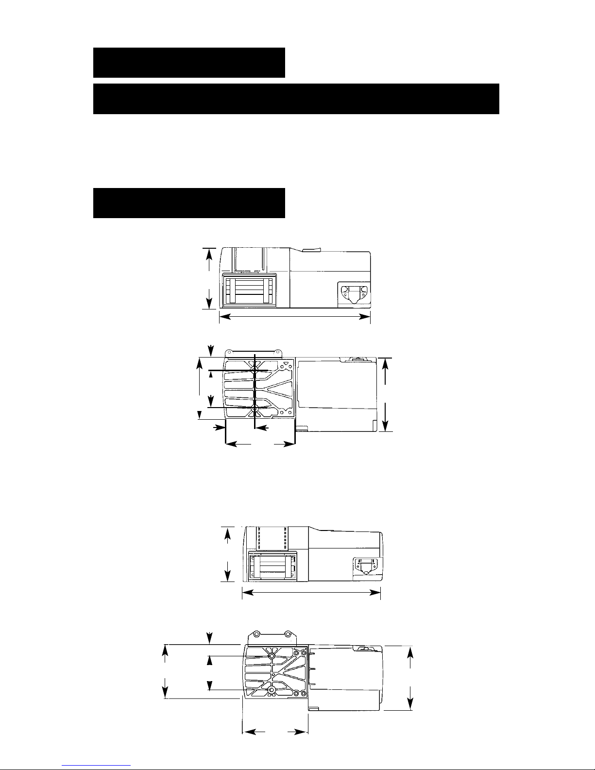
DIMENSIONS
15.1
(383)
3.1
(79)
1.24
(31.5
)
6.0
(152)
5.9
(150)
3.69
(93.7
7.1
(180)
7.2
(183)
MODELS 03002, 03005, 03010
4
MODEL 03000
6.0
(152)
15.1
(383)
7.1
(179)
3.69
(93.7)
5.9
(149)
1.25 (31.8)
7.1
(179)
NOTES:
1. All dimensions are in inches (millimeters).
2. Typical mount is to flat surface capable of handling
the loads. Bolts to be Grade 5 or better.
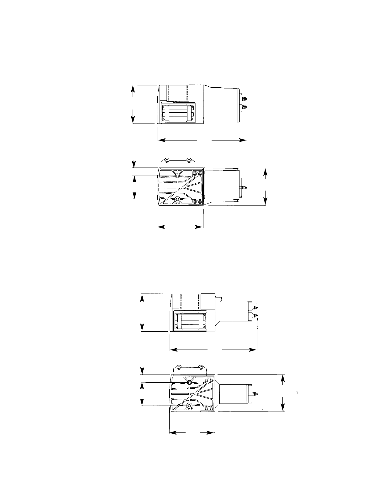
5
MODEL 03001
MODEL 03003
6.0
(152)
13.6
(346)
1.25 (31.8)
3.69
(93.7)
7.1
(179)
5.9
(149)
6.0
(152)
13.6
(346)
5.9
(149)
7.1
(179)
1.25 (31.8)
3.69
(93.7)
6
Do not use for
lifting, supporting, or transporting people, or over
areas where people are present.
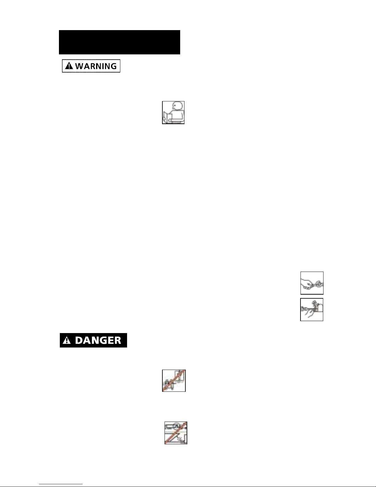
Disconnect power before servicing.
1. READ AND SAVE ALL
INSTRUCTIONS.
2. DO NOT OVERLOAD. See
Performance information. Do not
maintain power to the winch if
the motor stalls. Overloads can
damage the winch and create
unsafe operating conditions.
3. LEARN TO USE WINCH. After
installing your winch, take the
time to practice using it so that
you are comfortable with it when
the need arises. Periodically check
the winch installation to assure
that all bolts are tight.
4. NEVER ALLOW CHILDREN OR
UNTRAINED PERSONNEL TO
OPERATE WINCH.
5. INSPECT ELECTRIC CABLE FIT-
TINGS FOR TIGHTNESS BEFORE
EACH USE.
6. REPLACE DAMAGED OR BROKEN
PARTS IMMEDIATELY WITH MANUFACTURER’S RECOMMENDED
REPLACEMENT PARTS.
Never connect
winch to
110VAC power as fatal shock
may occur.
7. USE CAUTION WHEN using
the winch. KEEP PEOPLE,
PETS, AND PROPERTY
CLEAR OF THE PATH OF THE
LOAD. DO NOT USE WINCH TO
LIFT OR MOVE PEOPLE.
8. DO NOT USE THE WINCH TO
SUPPORT AN UNATTENDED
LOAD.
9. KEEP THE ELECTRIC CABLES FROM
HEAT, OIL, AND SHARP EDGES.
Periodically inspect for damage.
10. DO NOT OPERATE THE WINCH
WHEN TIRED OR UNDER THE
INFLUENCE OF DRUGS,
ALC0HOL, OR MEDICATION.
11. NEVER INSTALL WINCH IN SUCH
A WAY THAT THE WARNING
AND INSTRUCTION LABELS ARE
OBSCURED. Someone who has
not read this manual may need
to see them to understand the
proper operation of the winch.
12. Always operate the winch with
an unobstructed view of the
winching operation.
13. CHECK FOR CORRECT DIRECTION
OF ROTATION BEFORE USING
WINCH. The winch must be
properly wired to ensure correct
direction of drum rotation.
14. REMOVE AND STORE THE
REMOTE PENDANT ASSEMBLY IN
A SAFE PLACE when not in use
to prevent unauthorized use.
15. ALWAYS UNPLUG THE
REMOTE PENDANT BEFORE
WORKING IN OR AROUND
THE ROLLER FAIRLEAD OR
WINCH DRUM (THE DANGER ZONE) to prevent the
winch from being turned on
accidentally. Use handsaver
when winding end of wire rope.
16. When lifting a load, slowly take
up the slack until it becomes
taut. Stop, recheck all winching
connections.
17. DO NOT MACHINE OR WELD
ANY PART OF THE WINCH. Such
alterations may weaken the
structural integrity of the winch,
and void your warranty.
18. Never allow shock loads to be
applied to winch.
GENERAL SAFETY
INFORMATION
LOCATION
Mount the winch to a firm base.
The structure the winch is attached
to must be capable of withstanding
a load greater than 1-1/2 times the
winch’s rated line pull.
The winch can be mounted in a
horizontal or vertical position. Do
not mount the winch where there
would be the possibility of it being
submerged in water. The winch is
weather resistant but not waterproof.
This winch MUST
be mounted
with the pull in the underwind direction. Improper mounting could damage your winch, cause the brake to
not work and void your warranty.
Step (1)
Install structural support for winch.
See "Dimensions" section for winch
dimensions.
Step (2)
Mount the winch to the mount that
you have designed.
Mounting bolts supplied are the
correct length for use with a 1/4"
(6.3mm) thick mounting plate.
Do not substi-
tute any bolt
with strength weaker than
grade 5.
When attaching wire to the motor
terminals and solenoids (relays),
hold the inner nut when tightening
the outer nut. Do not allow the terminals to rotate. It may cause internal wire breakage or part misalignment. Be especially careful in preventing the solenoid (relay) terminals from rotating. Any rotation can
damage the solenoid (See Figure 1).
Step (3)
Disconnect the battery leads.
Batteries con-
tain gases
which are flammable and explosive.
Wear eye protection during installation and remove all metal jewelry.
Do not lean over battery while
making connections.
Step (4) Model 03003
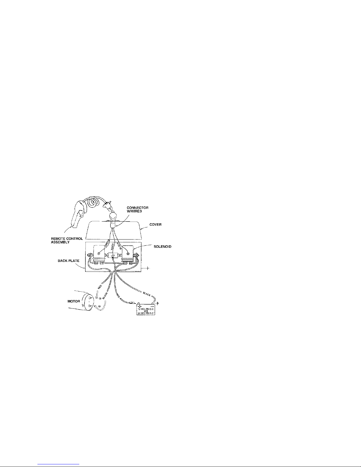
Select a convenient location for
mounting the Solenoid Remote
Control Assembly. The solenoid
INSTALLATION
Figure 1
7
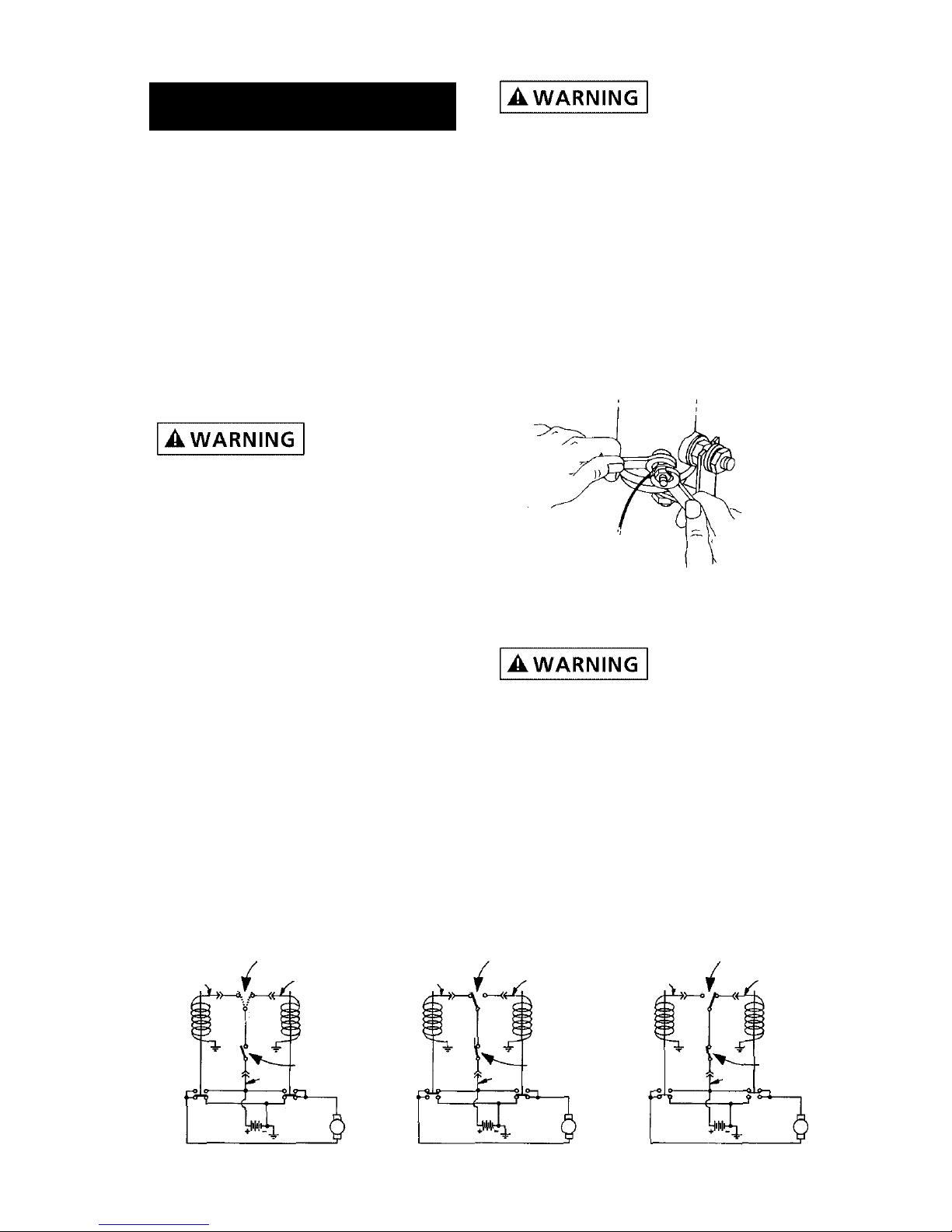
REVERSAL SWITCH
(Switch may be in
Either Position)
OFF
REVERSAL SWITCH
(Rope-In position)
WIRE ROPE IN
WIRE ROPE OUT
REVERSAL SWITCH
(Rope-Out position)
Electrical Schematic
Green
Black
4
3
1
Trigger
Switch
Load
Line
White
NC
NC
Winch
Motor
Green
Black
4
3
1
Trigger
Switch
Load
Line
White
NC
NC
Winch
Motor
Green
Black
4
3
1
Trigger
Switch
Load
Line
White
NC
NC
Winch
Motor
7
Figure 2
mounting plate must be electrically
grounded to the battery. If it is not,
the winch will not work. Preferably,
the solenoids should be mounted
vertically, with the solenoid end terminals pointing downwards.
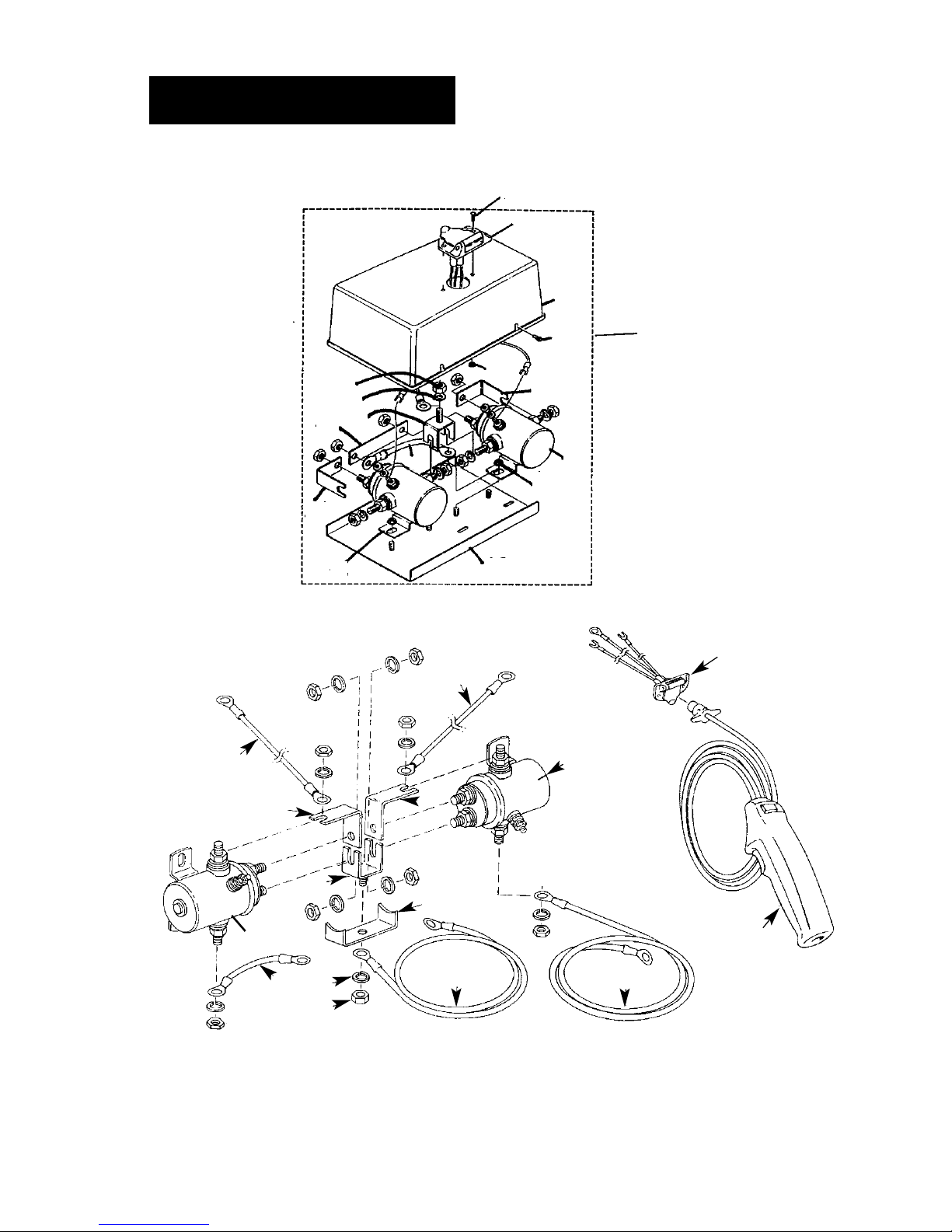
Electrical Connection
Cut two lengths of wire, one red
and one black, to reach from the
winch to the solenoids. When routing all wires, be sure to keep them
away from all hot or moving parts.
Crimp a 1/4" ring terminal on the
end of each wire at the winch end.
Attach one wire to each motor terminal (See figure 3). Crimp a 5/16"
ring terminal at the solenoid ends
of the wires and attach to the terminals on the solenoid assembly as
shown in Figure 3.
Cut and strip two lengths of wire,
one red and one black, to reach
from the solenoids to the battery.
On the battery end of the red wire,
install a 3/16 ring terminal, and
attach to the circuit breaker. The
other end of the circuit breaker
attaches to the harness. On the
opposite end of this wire, connect a
5/16 ring terminal and attach to the
solenoid assembly (See Figure 3).
Install 5/16 ring terminals to both
ends of the black wire. Connect one
end to the solenoid assembly, and
the other end to the battery negative terminal (See Figure 3).
Connect the circuit breaker assembly bracket to the battery positive
terminal.
Plug in the remote control, and with
the directional lever in the “Rope
Out” position, momentarily depress
the trigger to check for proper rotation direction of the winch drum. If
the winch runs in the wrong direction, reverse the wires connected to
the winch motor.
Step (4) Models 03000, 03001
These winches are supplied without
controls. To design the control system for your application, you can
purchase the needed materials to
complete your system from
Superwinch, or buy them locally.
You will need a switch or a solenoid
control, a circuit breaker, hook up
wire, and wire terminals.
Switch
Select a (3) position reversing switch
with a switch action of “momentary
on”/“off”/“momentary on”.
“Momentary on” means the switch
automatically returns to OFF position when released. Minimum contact rating must be 50 amp DC carry.
Superwinch offers a (3) Position
Heavy Duty Rotary Switch Part
Number 1591. The Superwinch switch
has an internal shunt that provides
dynamic braking to further assist the
winch's brake. (See Figure 4)
Solenoids
You will need (2) 12 Volt double
pole, double through solenoids,
with a continuous current rating of
80 amps on the normally open contacts and 60 amps on the normally
closed contacts.
8
Figure 3
Superwinch offers an external solenoid pack as shown with Model
03003. (Superwinch Part Number
1515A Remote Control). It comes
with 12 foot pendant, 20 feet of 8
gauge wire, and instructions.
Circuit Breaker
We recommend using a 40 Amp
Circuit Breaker between the battery
positive terminal and the wire that
goes to the switch or solenoid pack
(See Figure 5). This can be purchased from Superwinch as Part
Number 89-32341. The circuit breaker prevents overloads to the switch
and to the winch motor.
Hookup Wire
If the total length of wire required
is less than 20 feet, use 8 gauge
wire. If the total length of wire
required exceeds 20 feet, use 6
gauge wire.
Step (4) Models 03002, 03005,
03010
Route the (2) wires to the battery.
To ensure against insulation abrasion and/or cutting, apply several
layers of electrical tape where
wiring may come in contact with
sharp metal parts. Attach the circuit
breaker assembly to the end of the
blue terminated wire. Wrap the circuit breaker assembly with electrical
tape to prevent accidental short
circuits.
Note: If you choose to locate the
winch at a greater distance than
the wires provided will permit, it
may be necessary to purchase a larger gauge wire to get the best performance from your winch. If the
total length of additional wire to be
added to the system exceeds 10 ft.
(3m), use a larger wire gauge size.
Attach the circuit breaker directly to
the battery positive terminal, and
reattach the terminal to the battery.
Connect the remaining wire to the
battery negative terminal, and connect the terminal to the battery.
(See Figure 5)
Step (5)
Pull the trigger momentarily to
check wire rope drum rotation and
direction. If the drum rotates in the
wrong direction, recheck your
wiring.
The hand-held pendant switch activates a solenoid that activates
power to the winch motor. One
solenoid is for power-in (lifting a
load) motor direction and the other
is for power-out (lowering a load)
motor direction (See Figure 6).
9
Remote
Switch
Receptacle
Solenoid
Assembly
Motor
Green
Black
Black
Blue Terminated
White
Circuit
Breaker
Figure 5
+
Figure 4
10
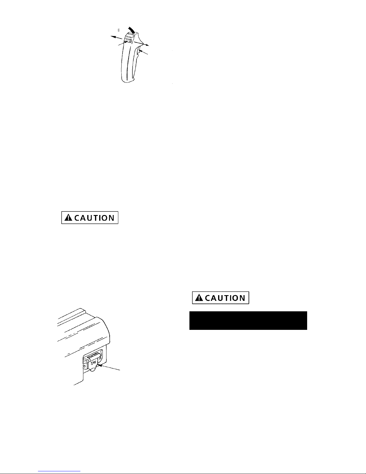
PENDANT OPERATION
The switch trigger returns to the
“OFF” position when released (See
Figure 6, Ref. A). The slide button
on the back of the switch determines the direction of the drum
rotation for lowering or lifting a
load (See Figure 6, Ref. B). The slide
is fitted with an interlock so that
the motor cannot be reversed if the
trigger is depressed. To change
direction, release the trigger, move
the slide button, and depress the
trigger again.
The switch
assembly must
be kept free of dirt and moisture to
ensure safe operation.
To connect the pendant control, lift
the dust cover on the plug receptacle (See Figure 7), and insert the
plug end of the remote switch. The
plug on the pendant control cord is
keyed and will fit into the socket
only one way.
Do not allow winch motor to overheat. The winch is for intermittent
use only. During long or heavy pulls
the motor will get hot. Allow to
cool after 2 minutes of “ON” time.
MAINTENANCE AND REPAIR
Periodically check tightness of
mounting bolts and electrical connections. Remove any dirt or corrosion that may have accumulated on
the electrical connections.
BRAKE OPERATION
Your winch has a wrap spring brake
that stops and holds loads up to
1,000 lb. (454 kg). When the winch
is powered out, as in releasing a
load, the brake is engaged and the
motor must overpower the brake
resistance to rotate the drum.
Therefore, it is normal for the
winch to operate faster in one
direction than the other. The brake
is designed for the wire rope to be
used in the underwind position
only. Drum must turn counterclockwise, looking from motor end,
when winching in.
DO NOT
OVERWIND.
Powering against the
brake will cause heat to build up in
the drum and may transfer heat to
the wire rope. DO NOT POWER OUT
FOR MORE THAN 2 MINUTES.
The drum may
get very hot.
WIRE ROPE
For safety reasons, it is important
that you use a wire rope with a
break strength of at least 5,600 lbs.
Recommended wire rope for this
winch will have a 1/4" diameter
with a 7 x 19 construction, and a
minimum break strength of 7,000
lbs. or a 7/32" diameter with 7 x 19
construction, with a minimum break
strength of 5,600 lbs.
OPERATION
Figure 6
POWER
OUT
POWER
IN
A
B
Figure 7
DUST
COVER
REPLACING THE WIRE ROPE
Replace damaged wire rope with
the manufacturer’s recommended
replacement part or a factory
approved equivalent identical in
strength, quality, lay, and stranding.
Pass the attaching end of wire rope
through the fairlead and attach it
to the drum. When inserting the
wire rope into the drum, insert it
into the correct end of the hole
provided (See Figure 8). Tighten the
set screw securely.
It is important that the wire rope be
wound tightly onto the drum.
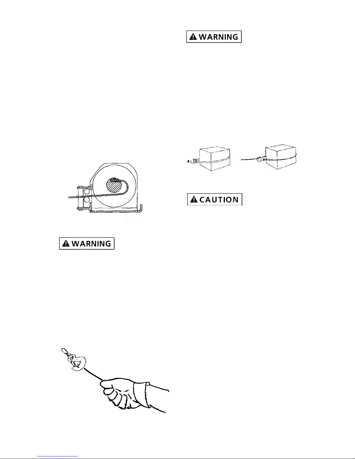
HANDLING THE WIRE ROPE
Use heavy
leather gloves
when handling wire rope. Do not
allow wire rope to slide through
hands.
1. Never winch with less than 5
turns of wire rope around winch
drum, since wire rope and fastener may not withstand the load.
ALWAYS USE HANDSAVER BAR
WHEN GUIDING HOOK FOR THE
LAST FEW FEET OF ROPE
(See Figure 9)
Keep clear of
winch wire rope
and hook when operating winch.
Never put your finger through thehook. Placing finger(s) in hook
could result in injury.
2. Never hook wire rope back onto
itself. Hooking wire rope onto
itself can damage rope. Use a
nylon sling (See Figure 10). When
using a sling, make sure that sling
is properly seated in saddle of
hook.
Avoid continu-
ous pulls from
extreme angles. This will cause wire
rope to pile up at one end of drum.
This can jam wire rope in winch
causing damage to rope or winch
itself.
3. Do not use wire rope as a ground
for welding.
4. Never touch welding electrode to
wire rope.
5. Keep wire rope tight and even on
drum.
6. Replace wire rope when frayed.
TIPS FOR EXTENDING THE LIFE OF
YOUR WINCH
1. Keep a tightly wound wire rope
drum. Do not allow the wire rope
to become loosely wound. A
loosely-wound drum allows a
wire rope under load to work its
way down into the layers of wire
rope on the drum. When this
happens, the wire rope may
become wedged within the body
of the windings, damaging the
11
Figure 10
Right
Wrong
Figure 8
Figure 9
wire rope. To prevent this problem, keep the wire rope tightly
and evenly wound on the drum
at all times. A good practice is to
rewind the wire rope under tension after each use. One way to
do this is to attach the hook to a
small load and winch that load to
rewind rope.
2. To maximize winch and wire rope
life, use pulley block to double
line heavier loads.
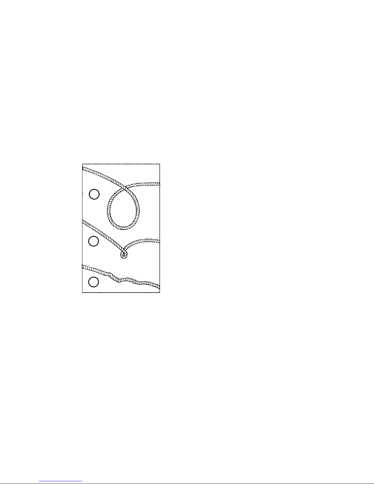
3. PREVENT KINKS BEFORE THEY
OCCUR. (See Figure 11.)
a. This is the start of a kink. At this
time, the wire rope should be
straightened.
b. The wire rope was pulled and the
loop has tightened to a kink. The
wire rope is now permanently damaged and must be replaced.
c. Kinking causes the wire strands
under the greatest tension to break
and thus reduces the load capacity
of the wire rope. The wire rope
must be replaced.
LUBRICATION
The winch is permanently lubricated. There may be grease leakage
out of winch, especially during first
few operations. This is normal and
it is not necessary to grease or oil
any internal part of winch at any
time.
Periodically lightly lubricate wire
rope with penetration oil and wipe
off excess.
Figure 11
a
b
c
12

TROUBLESHOOTING
CHART
Motor will not operate or 1. Damaged or stuck CAUTION Be prepared to
runs in one direction only solenoid disconnect power when
performing this test. If a
solenoid sticks once, it
is likely to stick again
and must be replaced
immediately
.
1. Tap solenoid to free stuck
contacts. Check by applying
voltage to the small solenoid
terminal. Be sure solenoid is
grounded back to source. A
solenoid that is not stuck will
make an audible “click” when
first energized.
2. Switch inoperative 2. Replace switch.
3. Broken wires or bad connection 3. Check for poor connections.
CAUTION Always use 2
wrenches (See Figure 1).
4. Damaged motor 4 Replace or repair motor.
5. Solenoids not grounded 5. Check the ground path
between battery negative and
solenoid base.
Winch will not shut off Solenoid stuck “ON” If a solenoid sticks on, reverse
direction and hold trigger switch
until the power lead can be disconnected. A safety disconnect
switch is available as an accessory.
Motor runs extremely hot 1. Long period of operation 1. Allow to cool.
2. Damaged motor 2. Replace or repair motor.
3. Damaged brake 3. Replace or repair brake.
Motor runs but with insufficient 1. Weak battery 1. Recharge or replace battery.
power or line speed Check charging system.
2. Battery to winch wire
extended with same size wire 2. Use larger diameter wire.
3. Poor battery connection 3. Check battery terminals for
corrosion. Clean as required.
4. Poor ground 4. Check and clean connections.
5. Damaged brake 5. Repair or replace brake.
Winch runs backward 1. Motor wires reversed 1. Recheck wiring.
2. Solenoids wired incorrectly 2. Recheck wiring.
Will not hold load 1. Excessive load 1. Reduce load or double line.
2. Worn or damaged brake 2. Repair or replace brake.
Symptom Possible Cause(s) Corrective Action
13
14
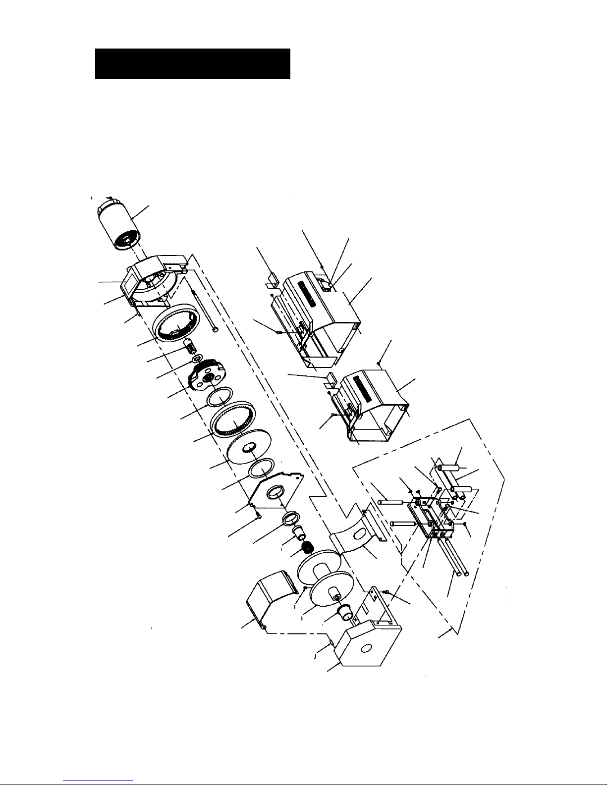
REPLACEMENT
PARTS
1
2
3
4
5
6
7
8
9
29
10
11
12
13
11
14
15
16
17
19
37
34
37
25
26
30
27
28
29
26
23
24
21
22
20
34
33
36
32
33
31
37&38
2
18
Safety
65

15
1 Base 89-52021 1
2 Groove pin 89-23303-01 2
3 Cable guard 89-32268 1
4 Main bearing 89-22268 1
5 Drum 89-40152 1
6 M6 x 1 x 8mm Set PT screw 90-23164-12 2
7 Brake spring 89-22342 1
8 Brake adapter 89-22287 1
9 Drum bearing 89-22269 1
10 Drum support 89-40092 1
11 Thrust washer 90-12574 2
12 Drive plate 89-32263 1
13 Rotating ring gear 89-32265 1
14 Planetary carrier assembly 89-22141 1
15 Wear washer 89-22271 1
16 Sun gear 89-32253 1
17 Stationary Ring Gear 89-32266 1
18 Housing Assembly 89-40157 1
19 12V Motor (03000, 03001, 03002, 03003, 03005) 90-33256 1
24V Motor (03010) 89-32386 1
20 Cable Tension Plate 89-32295 1
21 Screw, FCHSS M6 x 1 x 16 87-22291-02 4
22 Roller Fairlead Shaft (Includes 22-27) 1
23 Roller Fairlead Shaft (Long) 89-22334-02 2
24 Roller Fairlead Frame 89-40113 1
25 Roller Fairlead Shaft (Short) 89-22334-01 2
26 3/8 Retaining Ring 90-23029-08 4
27 5/8 x 2.352 Roller 90-12568-04 2
28 5/8 x 4.735 Roller 90-12568-06 2
29 M6 x 1 x 13mm BHDCS Screw 89-22290-01 2
30 M6 x 1 x 16mm BHDCS Screw 89-22290-02 5
31 Motor Cover Assembly (03000) 89-40131 1
(includes logo, 34 & 37)
32 Motor Cover Assembly (03002, 03005, 03010) 89-40131-03 1
(Includes logo, 34 & 37)
33 M4 x 0.7 x 6mm (03000, 03002, 03005, 03010) 89-22292-01 4
34 Filler Block (03000, 03002, 03005, 03010) 89-12032 1
36 SKT Half Connector (03002, 03005, 03010) 90-22115 1
37 8-32 Pan Head Screw (03000) 90-23032-03 1
8-32 Pan Head Screw (03002, 03005, 03010) 90-23032-03 3
38 8-32 Hex Flange Nut (03002, 03005, 03010) 90-23149-06 2
NS Handsaver Bar 89-32300 1
NS 1/4 x 25’ Wire Rope Assembly (03005) 1577B 1
NS 1/4 x 50’ Wire Rope Assembly (03010) 1577A 1
NS Pulley Block with Hook (03005) 2207 1
NS Mounting Hardware Package 90-22877 1
NS Terminal Package (03003) 90-22885 1
NS 12V Circuit Breaker Assembly (03002, 03003, 03005)87-22873-11 1
NS 24V Circuit Breaker Assembly (03010) 90-22873-01 1
(NS) Not Shown
Reference
Number Description Part Number Qty
REPLACEMENT
PARTS LIST
REPLACEMENT
PARTS
55
56
54
42
51
50
49
48
47
54
46
67
36
64
53
46
16
37
36
59
60
38
50
51
53
57
54
46
61
62
46
54
63
58

REPLACEMENT
PARTS LIST
46 12V Solenoid (03002, 03003, 03005) 90-20329 2
24V Solenoid (03010) 90-20331 2
47 6 GA x 5’ Leadwire Assembly (Pos) (03002, 03010) 90-23292-20 1
6 GA x 20’ Leadwire Assembly (Pos) (03005) 89-23292-27 1
48 6 GA x 5’ Leadwire Assembly (Neg) (03002, 03010) 90-20187-06 1
6 GA x 10’ Leadwire Assembly (Neg) (03005) 89-23292-26 1
49 Ground Strap (03002, 03005, 03010) 89-22356 1
50 5/16 Lockwasher (03002, 03003, 03005, 03010) 92-23057-03 1
51 5/16-18 Hex Nut (03002, 03003, 03005, 03010) 92-23034-04 1
52 6 GA x 3 1/2” Leadwire Assembly 90-23292-06 1
(03002, 03005, 03010)
53 Buss Bar 2 Assembly (03002, 03003, 03005, 03010) 92-10200 1
54 Buss Bar 1 (03002, 03005, 03010) 92-20126 2
55 8 GA x 9 3/8” Leadwire Assembly (Red) (03005) 89-23292-21 1
8 GA 9 3/8” Leadwire Assembly (03002, 03010) 90-20187-08 1
56 8 GA x 6” Leadwire Assembly (Black) (03005) 89-23306-02 1
6 GA x 6” Leadwire Assembly (03002, 03010) 89-23292-19 1
57 Buss Bar 3 (03003) 92-20128 1
58 6 GA x 2 3/4” Leadwire Assembly (03003) 90-20187-07 1
59 8-32 x 1/4 HW Taptite Screw (03003) 90-22247 1
60 8-32 x 1/4 HW Taptite Screw (03003) 90-23039-03 4
61 10-32 Flange Hex Nut (03003) 90-23149-01 4
62 Solenoid Pack Back Plate (03003) 90-32070 1
63 12V Remote Solenoid Pack (03003) 90-32139
(Includes 35, 36, 37, 46, 49, 52, 54, 60, 65, 66, 67, 68
64 Remote Control Assembly 90-22117 1
(03002, 03003, 03005, 03010)
65 Safety Label, 3/4” icon, 3 x 2 89-20330 1
Reference
Number Description Part Number Qty
17
 Loading...