

Page 1
ZIRCONIA SENSOR
THEORY
T4401
Issue 1
by Thomas H. Lotze
The zirconia carbon sensor is really
an oxygen sensor. The primary
mechanism for electrical current
flow in many ceramic electrolytes
is ionic conduction, in this case via
oxygen ions. T ypical construction,
basic theory, opening equations
and applications are covered.
INTRODUCTION
The purpose of this paper is to describe the typical zirconia carbon sensor in general terms, and
provide a thorough grounding in the mathematical equations governing it’s practical use.
COMMERCIAL SENSORS
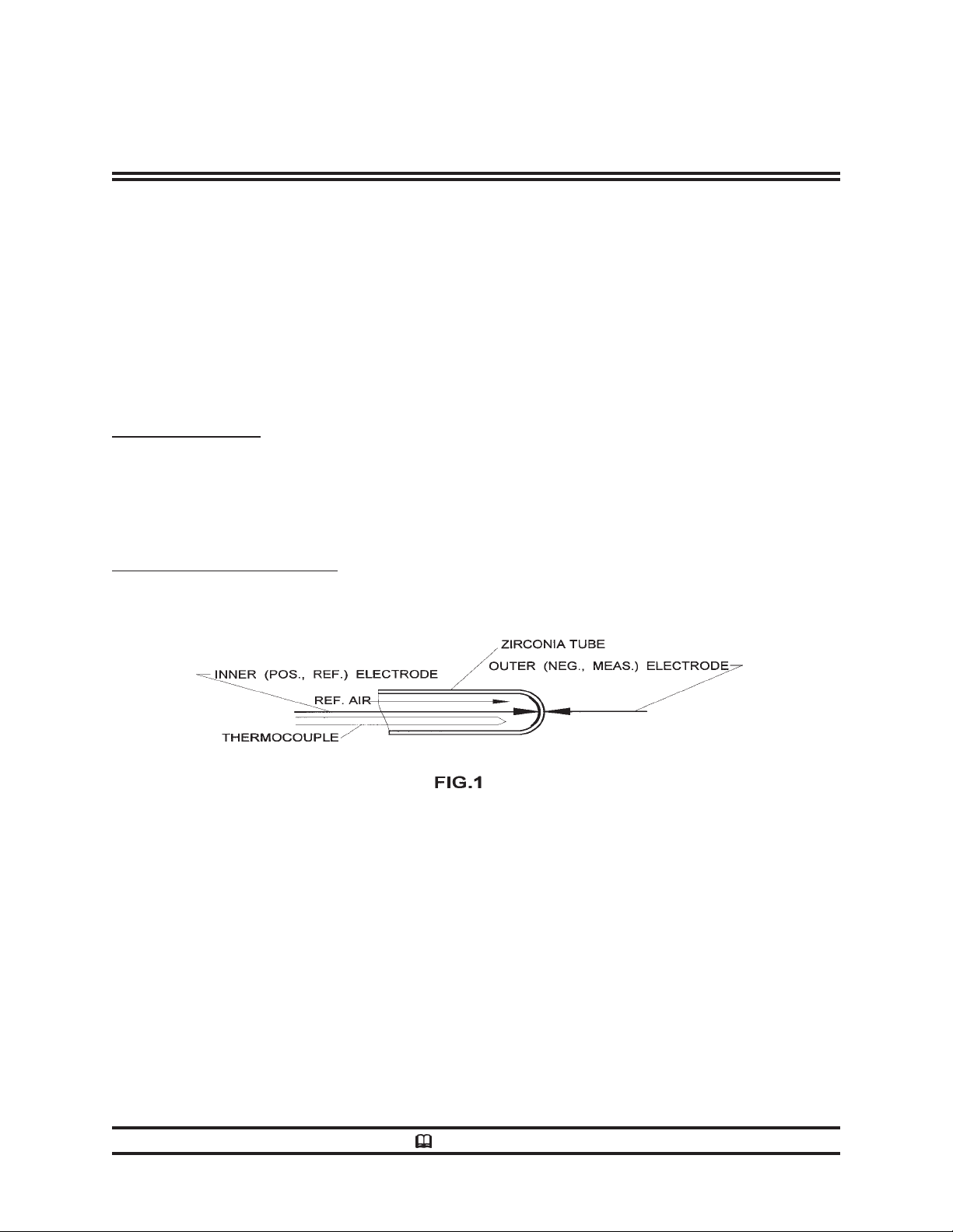
The basic elements of all commercial carbon sensors are shown in Fig. 1:
Technical Data
The tubular zirconia sensing element illustrated here is the preferred form for the SSi Gold Probe™.
Slip cast and fired at exceptionally high temperatures to provide a dense, non-porous body, this
component is not prone to develop the leakage paths that are common in probes using a cemented
zirconia plug in a tubular alumina body .
The inner, reference electrode, is spring loaded to hold it in intimate contact with the inner zirconia
surface. It consists of a specially formed extension of the lead wire that connects it to the probe
terminal block. The inner reference components are especially resistant to the normally oxidizing
reference atmosphere.
The outer, measuring electrode for most commercial probes is mechanically and electrically part of
the alloy protective sheath, and the zirconia substrate is spring loaded to make intimate contact with
this electrode. The SSi outer electrode, by virtue of premium quality, heat resistant alloy and a
proprietary surface treatment, is designed to survive the rigors of the harsh furnace atmosphere.
SUPER SYSTEMS TECHNICAL DATA SHEET
Printed in U.S.A.
SSi Super System Inc CINCINNATI, OH 45215
Page 2

T4401
Issue 1
ZIRCONIA SENSOR
THEORY
Technical Data
While probe manufacturers use a variety of materials and geometries, all properly designed sensors
will display precisely the same output when at equilibrium in a furnace atmosphere. Despite this
fact, many control instrument manufacturers will provide different algorithms for probes from
different manufacturers. This is primarily because manufacturers have derived their algorithms
using different sources for data that are not in complete agreement.
PRINCIPLES OF OPERATION
Pure zirconium oxide is a monoclinic crystalline material that transforms reversibly to a tetragonal
form at 1832°F with a large change in volume. This makes it unsuitable for normal refractory use.
If placed in solid solution, however, with 4% to 12% MgO, CaO or Y2O3, it is held in the stable
isometric (cubic) form which has no transformation in the range of heat treating atmospheres. By
virtue of the addition of these stabilizing oxides, oxygen ion vacancies are established in the crystal
lattice. The mobility of O- ions is greatly enhanced, and under certain conditions of temperature and
composition, the conductivity is entirely due to oxygen ions. This condition coincides with the
existence of the pure cubic crystalline phase, and is responsible for the oxygen sensing capability of
stabilized zirconia which will be discussed later.
A minimum quantity of the stabilizing oxides will ensure the existence of the pure cubic crystalline
phase of zirconia. When this amount is present, the zirconia is said to be fully stabilized. The
commercially available zirconia for oxygen sensors will have somewhat less than this minimum
amount, resulting in a “partially stabilized” electrolyte, having a better resistance to thermal fracture.
The zirconia in SSi sensors contains about 6 mole % (10.5 weight %) of Y2O3. The cell construction
of Fig. 1 demonstrates a characteristic typical of electrolytes having unity transference numbers for
an ionic species; there is an electromotive force displayed at it’s terminals that can be precisely
related to the corresponding molecular concentration at the two surfaces. In the case of cubic zirconia,
the cell e.m.f. is given by a form of the familiar Nernst equation,
EC=-.0275TR log10(p0/p1) millivolts (1)
where TR is the absolute temperature in degrees Rankine (= °F + 459.67), p0 and p1 are the oxygen
concentrations at the inner and outer electrodes respectively, stated in any units (usually in
atmospheres of partial pressure). Although there are applications where the oxygen present is the
only critical parameter, the heat treater is concerned with two other variables he wishes to control;
dew point and carbon potential. Fortunately, both parameters can be calculated directly from the
oxygen measurement.
SUPER SYSTEMS TECHNICAL DATA SHEET
page 2
Page 3

T4401
Issue 1
ZIRCONIA SENSOR
THEORY
Technical Data
DEW POINT This variable is utilized in control of endothermic generators that supply the basic
environment to a heat treating furnace. This environment, commonly called endo or Rx gas, is
created in the generator by combining air and a combustible such as natural gas or propane to
provide a mixture of about 20% carbon monoxide, 40% hydrogen and 40% nitrogen.
The reversible reaction that expresses the separation into oxygen and hydrogen by water is:
H2O
⇔
H2 + 1/2 O
2
By applying the principals of the law of mass action we can write an expression that accurately
describes the composition of the three components in a mixture at equilibrium:
(2)
KW = PH2 x PO
1/2
/ PH2O (3)
2
where KW is the temperature dependent equilibrium constant for this reaction and PH2, PO2 and
PH
O are the partial pressures of the corresponding materials, usually stated in atmospheres. This
2
equation dictates that a change of any of the variables causes the others to change as well in order
that equilibrium be sustained and the equation remains satisfied.The equilibrium constant is precisely
described by the following equation ( from Wagman1):
log10KW= 2.82 - 23000/T
R
(4)
The last relationship required to calculate the dew point from the measured variables is2:
log
O = 6.3979 - 4238.7/ (DP+460) (5)
10PH2
where the dewpoint, DP, is reported in degrees Fahrenheit. Combining equations (2) through (5),
we arrive at the SSi algorithm for dew point:
DP = (4238.7/(9.55731-log
+ (EC -1267.8)/0.05512TR)) - 460 (6)
10PH2
It is important to note here that there are only three specified variables in this algorithm. EC and T
are measured directly by the sensor which must include a close coupled thermocouple for precise
calculation. The third variable, PH2 may be measured by other analytical means. More commonly ,
as in the case of endothermic generators, it is assumed to be approximately 0.4 atmospheres. Because
it’ s value will vary with the control set point, the gauge pressure at the sensor, and other factors such
as peak shaving practices by the power company , it is commonly incorporated as part of a correction
factor in the control instrument. This factor is set to a value that causes the computed value of dew
point to agree with a manually measured value using a device such as the Alnor Dewpointer. The
individual correction factor is very stable. Accordingly, heat treaters find that the frequency of
manual dew point determination may be reduced significantly.
R
SUPER SYSTEMS TECHNICAL DATA SHEET
page 3
Page 4

T4401
Issue 1
ZIRCONIA SENSOR
THEORY
Technical Data
CARBON POTENTIAL The carbon potential (%C) of a heat treating atmosphere is defined as
“that value of carbon concentration achieved in a coupon of shim stock exposed to the atmosphere
until it has reached equilibrium”. The time required for this equilibration will vary with shim thickness
and furnace temperature. Table 1 illustrates the approximate effects.
Table 1 Time to equilibrium (minutes)
SHIM THICKNESS
TEMP 0.003" 0.005" 0.007"
1550 63 117 173
1600 50 91 136
1650 39 72 107
1700 32 58 86
1750 26 47 70
Corresponding to the reaction (2) for dew point calculations is the following reversible reaction
encountered in the furnace atmosphere:
CO
⇔
C +1/2 O
2
(7)
The mass action equilibrium equation for this reaction is:
1/2
/PCO (8)
2
where K
KCO = aC x PO
is the temperature dependent equilibrium constant, PO2 and PCO are the partial pressures
co
of oxygen and carbon monoxide and aC is the carbon activity-- a concentration term similar to the
partial pressure. As before, this equilibrium constant is a function of temperature (from W agman et al)1:
log10KCO = 4.5713 + 10638/T
R
(9)
Finally, the carbon activity aC has been experimentally related to %C (from Collin et al)3:
3751/T
aC= 1.07 q (10
R
)(C/(1-19.6C)) (10)
where q is a function of the alloy being treated, and is calculated as shown in Appendix A. Combining
(1), (8), (9) and (10) and rearranging, we derive the SSi algorithm relating %C to the measured
variables from the sensor:
%C = 3.792 eZ / ((324.3q / PCO) + eZ ) (11)
where Z = (EC - 820.7)/ 0.0239 T
SUPER SYSTEMS TECHNICAL DATA SHEET
R
page 4
Page 5

T4401
Issue 1
ZIRCONIA SENSOR
THEORY
Technical Data
Note that the value q/PCO is the correction factor, (or a simple function of the correction factor)
that is provided in most commercial controllers to make the calculated value of %C agree with shim
stock tests.
PRACTICAL CONSIDERATIONS
Properly maintained, the zirconia sensor provides the valuable characteristic of repeatability to the
heat treater. Periodic standardization using shim stock tests or dew point tests to establish the
appropriate correction factors will ensure repeatability , and hence product quality assurance. Although
the purist may frown at the use of such “fudge factors”, the practical considerations overwhelmingly
dictate their use. It may be found that the value of the correction factor will vary , at the extremes of
temperature and carbon potential. Appropriate values should be determined throughout the operating
region, and applied judiciously.
APPENDIX A- CALCULATION OF ALLOY FACTOR “q”
The value of q for carbon steels is close to 1.00. When alloying elements are incorporated in the
steel, it is desirable to calculate an additive factor to adjust the value of q, using the formulae in the
following table (from Neumann and Person)4:
To correct for add this value to q (= 1.00)
Silicon 0.15 %Si + 0.33 o/oSi
2
Manganese 0.0365 %Mn
Chromium -0.13 %Cr + 0.0055 %Cr
Nickel 0.03 %Ni + 0.00365 %Ni
Molybdenum -0.025 %Mo-0.01 o/oMo
Aluminum -0.03 %Al - 0.02 %Al
Copper -0.016 %Cu - 0.0014 %Cu
Vanadium -0.22 %V + 0.01 %V
2
2
2
2
2
2
REFERENCES
1. D.D. Wagman et al. J. Res. Burl Standards, 1945, 34, 143.
2. Metals Handbook 9th Ed., Vol. 4, 145.
3. R. Collin et al. J.I.S.I., Oct. 1972, 788.
4. F. Neumann and B. Person, Hart.-Techn. Mitt., 1968, 23, 296.
SUPER SYSTEMS TECHNICAL DATA SHEET
page 5
Page 6

ZIRCONIA SENSOR
THEORY
T4401
Issue 1
Technical Data
Notes
SUPER SYSTEMS TECHNICAL DATA SHEET
SSi
7205 EDINGTON DRIVE * CINCINNATI, OH 45249
SUPER SYSTEM INC.
(800) 666-4330 • (513) 772-0060 • (513) 772-9466
 Loading...