


 Loading...
PGA3510
Portable Multi-Gas IR Analyzer
(CO, CO2, and CH4 Gas Analyzer with O2 and Optional H2 Measurement and
% Carbon, % Dissociated Ammonia, % NH3, KN, and
KC Calculation Capabilities)
Operations Manual
Please read, understand, and follow these instructions before operating this equipment. Super Systems, Inc. is not responsible for damages incurred due to a failure to comply with these
instructions. If at any time there are questions regarding the proper use of this analyzer, please contact us at (800) 666-4330 for assistance.
PGA3510 Operations Manual
Super Systems Inc. |
Super Systems Europe |
USA Office |
Units 3 & 4, 17 Reddicap Trading Estate, |
Corporate Headquarters |
Sutton Coldfield, West Midlands |
7205 Edington Drive |
B75 7BU |
Cincinnati, OH 45249 |
UNITED KINGDOM |
Phone: (800) 666-4330 |
Phone: +44 (0) 121 329 2627 |
http://www.supersystems.com |
http://www.supersystemseurope.com |
|
Super Systems China |
Super Systems Mexico |
No. 335 XianXia Road |
Sistemas Superiores Integrales S de RL de CV |
Room 308 |
Querétaro, QRO CP, MEXICO 76120 |
Shanghai, CHINA |
Phone: +52 (442) 410 9040 |
200336 |
http://www.supersystems.com |
Phone: +86 21 5206 5701/2 |
|
http://www.supersystems.com |
Super Systems Inc. |
Page 2 of 33 |
PGA3510 Operations Manual |
|
Table of Contents |
|
Introduction................................................................................................................................................... |
4 |
Specifications ................................................................................................................................................ |
5 |
Unpacking the Device.................................................................................................................................... |
5 |
Basic Operating Description ......................................................................................................................... |
6 |
Default Screen .............................................................................................................................................. |
6 |
Pump Operation ............................................................................................................................................ |
7 |
Carbon Calculation........................................................................................................................................ |
7 |
Chart ............................................................................................................................................................. |
8 |
Chart Sub Menu ........................................................................................................................................... |
9 |
Menu Lists................................................................................................................................................... |
10 |
Carbon Calculation .................................................................................................................................... |
12 |
Nitrider Calculation ................................................................................................................................... |
12 |
Sessions..................................................................................................................................................... |
13 |
Pump Control............................................................................................................................................. |
15 |
Sensor Calibration..................................................................................................................................... |
15 |
Performing a Zero Calibration.............................................................................................................. |
16 |
Use of a CO2 Scrubber for Zero Calibrations........................................................................................ |
17 |
Performing a Span Calibration ............................................................................................................. |
17 |
Calibrating the Oxygen Sensor ............................................................................................................. |
17 |
Automatic Sampling Parameters.............................................................................................................. |
18 |
COF/PF Adjustment Increment............................................................................................................. |
19 |
COF/PF Adjustment Interval (minutes) ................................................................................................ |
19 |
Minimum COF / PF Value...................................................................................................................... |
19 |
Maximum COF / PF Value ..................................................................................................................... |
19 |
COF / PF Adjustment Mode................................................................................................................... |
19 |
Communications and Source Setup.......................................................................................................... |
20 |
IP Address ............................................................................................................................................. |
20 |
Atmosphere/Temp Sources.................................................................................................................. |
21 |
Port Setup ............................................................................................................................................. |
22 |
Instrument Setup....................................................................................................................................... |
23 |
Calculation Factors ............................................................................................................................... |
23 |
General Setup........................................................................................................................................ |
23 |
Security Settings ................................................................................................................................... |
24 |
Factory Default Settings ....................................................................................................................... |
24 |
Other Settings ....................................................................................................................................... |
24 |
Language Setup .................................................................................................................................... |
24 |
Instrument Information............................................................................................................................. |
24 |
General Information.............................................................................................................................. |
24 |
Calibration Dates .................................................................................................................................. |
24 |
Power Status ......................................................................................................................................... |
25 |
Tools........................................................................................................................................................... |
25 |
Database Maintenance.......................................................................................................................... |
25 |
Pressure Sensor Calibration ................................................................................................................ |
26 |
Thermister Calibration.......................................................................................................................... |
26 |
SuperCalc.............................................................................................................................................. |
26 |
User Manual .......................................................................................................................................... |
26 |
Set User Cal / Load User Cal ................................................................................................................ |
26 |
Calibration Log...................................................................................................................................... |
26 |
Analog Input Calibration ....................................................................................................................... |
26 |
Valve Setup............................................................................................................................................ |
29 |
Parts List..................................................................................................................................................... |
31 |
Warranty...................................................................................................................................................... |
32 |
Revision History .......................................................................................................................................... |
33 |
Super Systems Inc. |
Page 3 of 33 |
PGA3510 Operations Manual
Introduction
The Model PGA3510 (see part numbers in the Parts List on page 31) is a portable Multi-Gas IR analyzer with an Oxygen (O2) cell. It measures Carbon Monoxide (CO), Carbon Dioxide (CO2) and Natural Gas (CH4) typically found in an endothermic atmosphere. The measurement of these gases, combined with furnace temperature information, allows the PGA3510 to calculate the percent Carbon (%C) of the measured gas. A Hydrogen (H2) sensor can also be incorporated as an option to provide a more complete picture of the measured gas.
For nitriding and ferritic nitrocarburizing (FNC) applications, the PGA3510 can calculate carburizing potential (KC) and nitriding potential (KN).
Finally, the PGA3510 can be configured for compatibility with environments containing ammonia (NH3) gas. NH3 compatibility must be specifically requested when the PGA3510 is ordered.
IMPORTANT!
Do not use a PGA3510 for gas analysis with NH3-containing gas if the PGA3510 has not been configured with NH3 compatibility. Any use of a non-NH3 compatible PGA3510 with NH3- containing gas will void the product warranty.
Super Systems Inc. |
Page 4 of 33 |
PGA3510 Operations Manual
Specifications
The unit is designed and manufactured for the atmosphere heat treating industry; however, its uses go beyond the scope of these applications.
CO range: |
0.00 to 30.00 % |
CO2 range: |
0.000 to 2.000 % |
CH4 range: |
0.00 to 15.00 % |
O2 range: |
0.1 to 25.0% |
H2 range: |
0.00 to 100% |
* Note: These sensors have been optimized for use at the levels normally seen in an Endothermic atmosphere. The ranges can be adjusted to fit other applications. For information regarding modifications to the ranges shown above, please contact Super Systems.
Sampling method: |
Extraction by internal pump (when necessary) |
Measurement Method (CO, CO2, CH4): |
Non-Dispersive Infrared (NDIR) |
Measurement Method (O2): |
Electrochemical |
Measurement Method (H2): |
Thermal Conductivity |
Accuracy and repeatability: |
± 1% of full scale |
Recommended Calibration Interval: |
Annual |
Flow Meter: |
Inside case lid and also on-screen |
AC Power Requirements: |
90 to 230 VAC, 50 to 60 Hz, 60 Watts |
DC Power Source: |
12VDC rechargeable NiCd battery with Integral charger |
Communications: |
Ethernet, USB(A), USB(B), RS485 Modbus |
Data Storage: |
Continuous automatic data logging |
Data Retrieval: |
XGA Viewer Software (included) or on-screen |
Operating Temperature: |
32° to 122° F (0° to 50° C) |
External Dimensions: |
Approx. 16”H X 20”L X 8”D |
Weight: |
Approx. 28 lbs. |
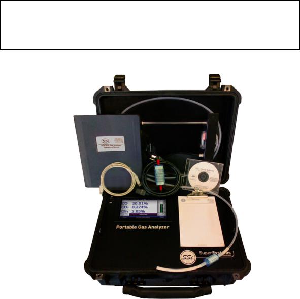
Unpacking the Device
The following items should be included with the PGA:
1.Portable Gas Analyzer
2.Bowl Filter
3.Sample Tubing
4.In-Line Filter
5.Notepad
6.Touch Screen Stylus
7.XGA Viewer Software CD
8.USB Cable
9.CO2 Scrubber
10.Power Cord
11.Product Manual
Super Systems Inc. |
Page 5 of 33 |

PGA3510 Operations Manual
Basic Operating Description
The Model PGA3510 has been designed for the simultaneous analysis of CO, CO2 and CH4 in heat-treat furnace atmosphere gases. It uses a color touch screen display / operator interface for data entry and for viewing. Selections can be made on the screen using a finger or a stylus. Avoid the use of sharp objects (pens, paperclips, screw drivers, etc.) as they can cause permanent damage to the screen and void the warranty of the instrument.
After the power switch is turned on, it will take approximately 30 seconds for the PGA3510 software to automatically load. Once the software is properly loaded, the instrument is ready to use. When the power switch is turned off, the PGA3510 initiates a controlled shutdown procedure which takes about 15 seconds. Following the controlled shutdown, the instrument will completely turn off.
Hydrogen Cell Note:
For highest H2 accuracy, it is recommended that the instrument be powered on for 60 minutes before measurements are taken.
Default Screen
Once the PGA3510 has successfully loaded its software, the default screen will be displayed.
A
L
B K
C
D E F G H I J
A – Measured values of CO, CO2, and CH4 (and H2, if the H2 sensor is present)
B – Pump status indicator / Button to change pump status
C – Button to access menu list
D – Session status indicator
E – Temperature / Instrument Temperature indicator
F – Button for Carbon Calculation screen
G – Automatic Carbon Calculation Adjustment indicator
H – External Instrument Communications status indicator
I – Measured value of Oxygen
J – Button for Trend Chart screen
K – Numeric Flow indicator
L – Visual Flow indicator
Super Systems Inc. |
Page 6 of 33 |

PGA3510 Operations Manual
Pressing the Return button at the bottom right of the operator interface on any screen will take the display to the default. It may be necessary to press the Return button multiple times.
Pump Operation
Initially, the pump will be off. The pump should remain off while sampling an endothermic generator or any other atmosphere under positive pressure. The pump should also remain off during calibration. For proper operation, the flow of gas through the sensors should be between 1.0 and 2.0 SCFH. If the flow meter on the right of the screen or on the inside of the lid does not indicate sufficient flow, turn the pump on. When accessed from the main screen, the pump has two possible modes: On and Off.
Carbon Calculation
The PGA3510 determines the percent carbon in the sample gas using measured amounts of CO, CO2, and CH4 along with the Furnace Temperature. The Furnace Temperature is either entered by the user or obtained automatically from the Furnace Temperature Controller via RS-485 communications.
Additionally, the carbon percentage measured by the PGA3510 can be used as a comparison to the carbon percentage measured by a furnace’s oxygen probe. This is accomplished either by manually entering the Probe Temperature, Probe Millivolts, and the Probe CO Factor into the PGA3510 or by obtaining the information automatically via RS-485 communications to the Furnace Carbon Controller. Providing the probe information allows the PGA3510 to suggest an adjustment for the probe CO Factor (or Process Factor) in order to keep the oxygen probe measuring properly.
Super Systems Inc. |
Page 7 of 33 |

PGA3510 Operations Manual
Using infra-red analysis is considered a more accurate method for determining the percent carbon of a gas compared to using an oxygen probe alone. The single point oxygen probe assumes a theoretical mixture of endothermic gas to infer the percent carbon whereas the gas analyzer will measure the exact composition of the process gas. The percent carbon determined by the gas analyzer can then be used to adjust the carbon percentage determined by the oxygen probe.
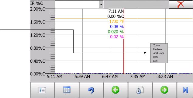
Chart
The Chart Display shows between 1 hour and 24 hours of process variable data on the screen and can be scrolled back to view all of the data stored on the flash card. The vertical timelines change as the time changes on the screen. The function buttons run along the bottom of the screen.
The Trend Lines button -  - will allow the user to select or de-select the trend lines on the trend chart to display. If the checkbox next to each trend line is checked, then that trend line will be displayed.
The Datagrid View button -  - will display a screen with the trend data in a grid format instead of with trend lines. The trend data is shown in 1-minute intervals. Clicking on the OK button on this screen will close the screen down and return to the Chart Display screen.
The Refresh button -  - will refresh the screen’s trend data if the screen is not in real-time mode.
The left-pointing green arrow button -  - will move the chart’s view backward in time by the specified chart interval.
The chart interval button -  - will determine the number of hours displayed on the trend chart. The options are: 1 Hour, 2 Hours, 4 Hours, 8 Hours, 12 Hours, or 24 Hours.
Super Systems Inc. |
Page 8 of 33 |
PGA3510 Operations Manual
The right-pointing green arrow button -  - will move the chart’s view forward in time by the specified chart interval.
The right-pointing arrow with the vertical line next to it button -  - will toggle between viewing the chart in or out of real-time. When in real-time mode, the chart will automatically be updated once a minute.
Chart Sub Menu
There is a sub-menu available by putting a finger or a stylus anywhere on the chart and holding it there for a couple of seconds. The sub-menu will have the following options available: Zoom, Restore, Add Note, Data, and Exit.
The Zoom option will allow the user to zoom in on a particular part of the screen. Once this has been selected, the user can take a stylus or a finger and create a box around the data. Once the user releases the stylus or finger, a zoom is no longer possible, and the user will need to re-select the option from the sub-menu to zoom in again.
The Restore option will back out of any zoom options that have been performed and display the initial chart screen.
The Add Note option allows the operator to enter a note on the chart, similar to writing on a paper chart. The note is available when the chart is printed out using the utility software included with the Series 9010 instrumentation. Pressing the Add Note option displays a screen where the operator can enter the operator ID or initials and a note. The user has the option to enter a note using either the operator interface keyboard and typing or using the Signature mode and writing the note with the stylus.
Super Systems Inc. |
Page 9 of 33 |
PGA3510 Operations Manual
The Data option will show the trend data as a data grid instead of the trend lines on a chart. This
functionality is exactly the same as if the user pressed the Datagrid View button -  - from the chart screen.
Exit will close out the sub-menu without selecting an item.
Pressing the red ‘X’ in the top right-hand corner of the screen will take the user back to the status screen.
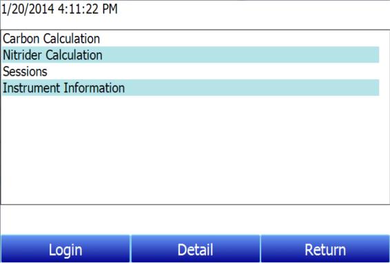
Menu Lists
Accessing the menu screen will show four available options.
Carbon Calculation, Nitrider Calculation, Sessions, and Instrument Information can be accessed by any users. Additional menu items are available when an authorized user logs in using an appropriate Pass Code. When the Supervisor Pass Code is entered (default = 1), the user will also be able to access the Pump Control screen.
Super Systems Inc. |
Page 10 of 33 |
Loading...