

Page 1

Data Acquisition (DAQ)
Operations Manual
Super Systems Inc
7205 Edington Drive
Cincinnati, Ohio 45249
513-772-0060/800-666-4330
Fax: 513-772-9466
www.supersystems.com
Page 2

Table of Contents
Overview ................................................................................................................................................................ 3
SSi DAQ Wiring Diagram .......................................................................................................................................... 4
SSi DAQ Setup ......................................................................................................................................................... 5
Step 1 – Install Configurator 2.0 on the Local Computer .......................................................................................... 5
Step 2 – Connect the SSi DAQ to a Network or Local Computer ................................................................................ 7
Step 3 – Configure Configurator 2.0 on the local computer ....................................................................................... 8
Step 4 – Complete Configurator Range Setups Menu Option ..................................................................................... 9
Step 5 – Complete Configurator Input Offsets Menu Option.................................................................................... 10
Analog Inputs ........................................................................................................................................................ 11
Adding a Jumper to an Input ............................................................................................................................ 11
Thermocouple connections ............................................................................................................................... 11
Voltage connections ........................................................................................................................................ 11
4 – 20 mA. Current Loop connections ............................................................................................................... 12
Setting the DIP switches to Assign Board Numbers ............................................................................................ 12
Configurator Menu ................................................................................................................................................. 13
Input Values ...................................................................................................................................................... 13
Aux Instruments ................................................................................................................................................. 14
Communication Setup ......................................................................................................................................... 15
Device Configuration ........................................................................................................................................... 17
Range Setups ..................................................................................................................................................... 18
Input Offsets ...................................................................................................................................................... 19
Aux Instrument Setup ......................................................................................................................................... 20
Custom Curves ................................................................................................................................................... 21
Calibration ......................................................................................................................................................... 22
Zero/Span Calibration ...................................................................................................................................... 22
Cold Junction Offset ........................................................................................................................................ 23
Satellite Boxes – SR3, SR6 ...................................................................................................................................... 24
DAQ Data Sheets ................................................................................................................................................... 25
Appendix 1 – Input Number Table ........................................................................................................................... 27
Appendix 2 - Input Ranges ..................................................................................................................................... 28
Revision History ..................................................................................................................................................... 29
4576 DAQ Manual Revision A Page 2 Super Systems Inc
Page 3

OOvveerrvviieeww
The SSi DAQ data acquisition module is a simple, powerful and expandable product for measuring a vast array of signals
in the process control environment. The DAQ can be used with as few as 3 inputs and can be expanded to as many
as 48 per DAQ depending upon your needs. Each SSi fully-isolated 3 input analog module can be configured on an inputby-input basis for a range of voltage inputs from as little as 20 mV to as much as 10V or for a 4 - 20 mA current signal.
Communications to the DAQ are available via Modbus serial protocol or through the DAQ's Ethernet port via
ModbusTCP. Calibration and configuration are available through SSi's Configurator software (provided) and the DAQ
also features a limited web server for simple interfacing from any PC in your plant (Ethernet communications required).
4576 DAQ Manual Revision A Page 3 Super Systems Inc
Page 4
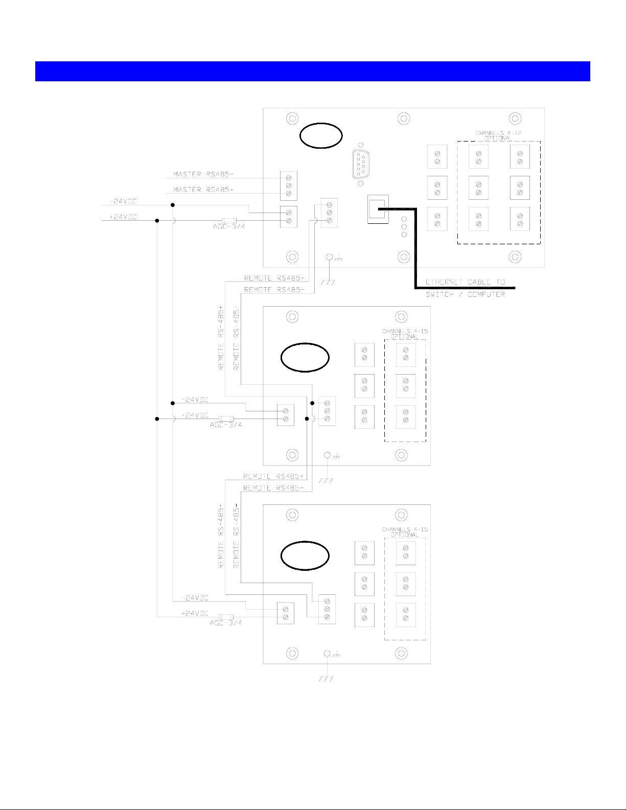
SSSSii DDAAQQ WWiirriinngg DDiiaaggrraamm
RS232
SSi
CINCINNATI, OHIO
RS485
HOST
-
S
+
+
24V
DC
REMOTE
SSi
CINCINNATI, OHIO
+
24V
DC
REMOTE
RS485
RS485
HOST
-
S
+
ETHERNET
3
2
-
S
1
+
-
6
+
-
5
+
-
4
+
12
3
2
1
-
6
+
-
5
+
-
4
+
12
+
+
+
-
9
+
-
8
+
-
7
+
+
+
+
3
SSi
CINCINNATI, OHIO
+
24V
DC
REMOTE
RS485
3
2
-
S
1
+
-
6
+
-
5
+
-
4
+
12
+
+
+
4576 DAQ Manual Revision A Page 4 Super Systems Inc
Page 5
SSSSii DDAAQQ SSeettuupp
This section will explain how to set the SSi DAQ up. The steps required to set up the SSi DAQ through a local computer
are:
1. Install Configurator 2.0 on the local computer
2. Connect the SSi DAQ to a network or local computer
3. Configure Configurator 2.0 on the local computer
4. Complete Configurator
5. Complete Configurator
Range Setups
Input Offsets
menu option
menu option
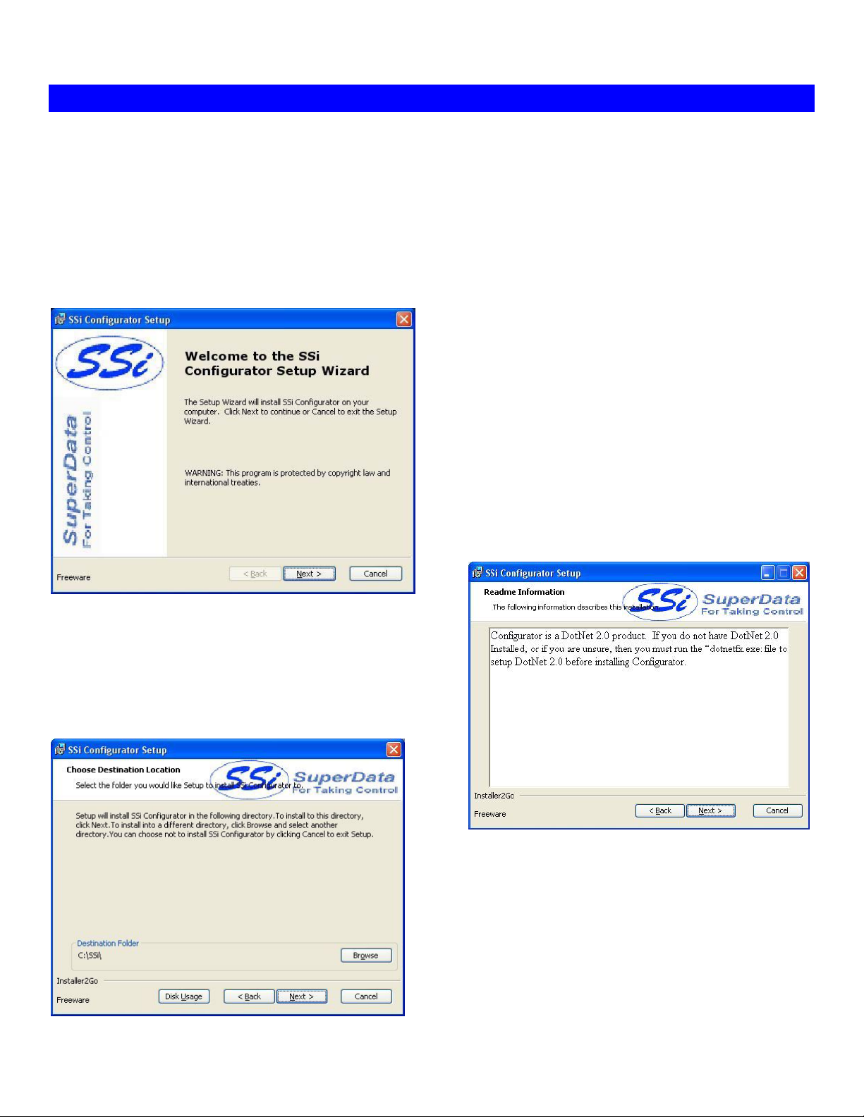
Step 1 – Install Configurator 2.0 on the Local Computer
Configurator 2.0 is a configuration utility developed by SSi
that will allow the user to interface with an SSi instrument
directly or over a network. The installation file,
ConfiguratorSetup.msi, should be included with the
installation CD
provided by SSi. If this file is not on the CD, contact Super
Systems at 513-772-0060.
Double-click on the installation file to begin the installation
process.
The first page displayed is just for information purposes.
Click on the Next > button to move to the next page, or
press the Cancel button to cancel the installation.
The second page is a warning about Configurator 2.0. Since
Configurator 2.0 is a Microsoft .Net 2.0 product, the local
computer will have to have the .Net 2.0 framework installed
before Configurator 2.0 can be used. Click on the Next >
button to continue or the Cancel button to cancel the
installation.
Page 3 will allow the user to select the location of the
installation. The default location is “C:\SSi\”. To change this
location, click on the Browse button and select a new location
from the dialog box that is displayed. The Disk Usage button
is a utility that will display the available hard drive space on the
local computer. Click on the Next > button to move to the
next page.
4576 DAQ Manual Revision A Page 5 Super Systems Inc
Page 6
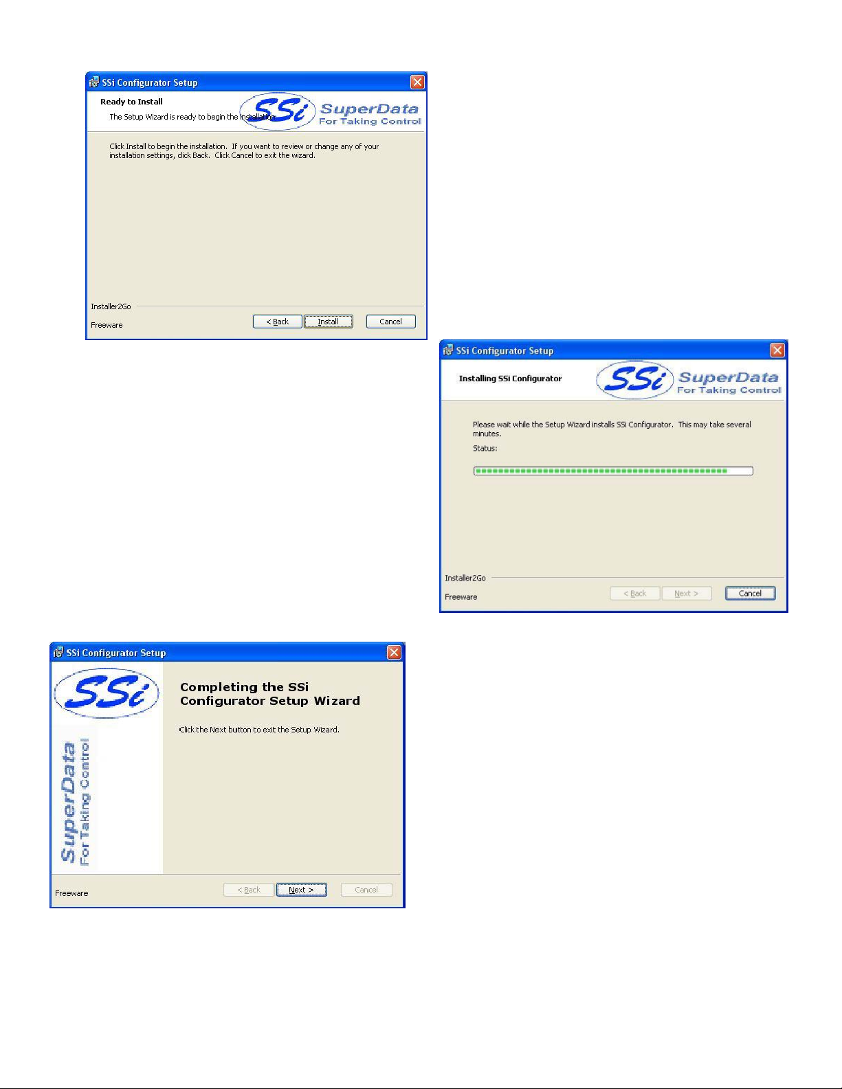
Page 4 will allow the user to review the installation
settings, if necessary. Click on the Install button to install
the software.
Page 5 will display a progress bar as the installation proceeds.
Note: The installation should only take a few minutes
4576 DAQ Manual Revision A Page 6 Super Systems Inc
.
Page 6 is the finishing screen, which is displayed after the
software has been installed. Click on the Next > button to
continue.
Page 7
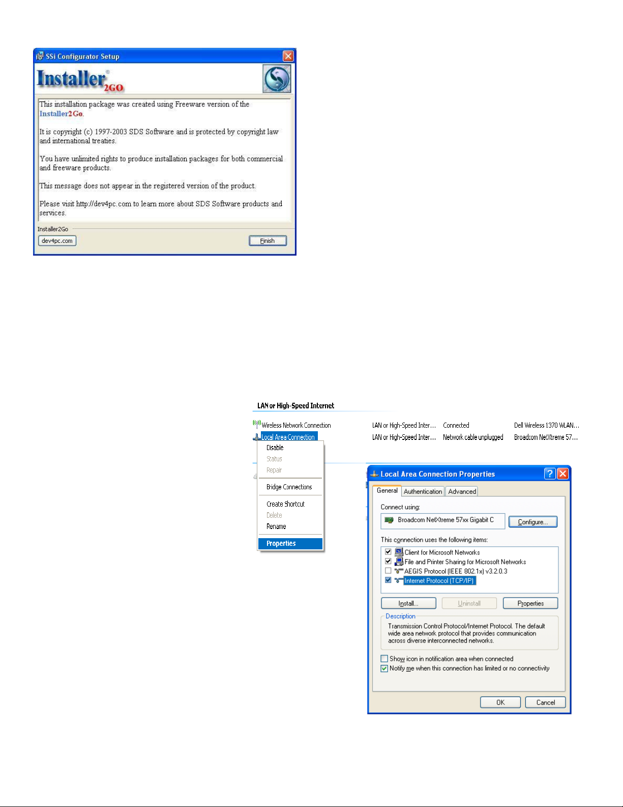
Page 7 is the informational screen about the makers of the
installation software. Click on the Finish button to close out
this screen.
Step 2 – Connect the SSi DAQ to a Network or Local Computer
To connect the instrument to the network, through a wall port or switch, use a regular Ethernet cable. To connect the
instrument directly to a computer, use an Ethernet crossover cable. Contact your IT Department for the necessary
cables. Once the DAQ is connected to a network, the Configurator 2.0 software will be able to find it during any
searches. Connecting the instrument to your network or directly to a PC is accomplished using the Ethernet port on the
instrument. If you are connecting the instrument to your network, you will need an Ethernet cable. The cable is plugged
into the instrument Ethernet plug and then other end should be plugged into a network hub. If the IP Address of the
instrument needs to be changed, this can be done through the Configurator software (see Step 3 below). If you are not
putting the instrument on the network, you
should use an Ethernet crossover cable.
Ethernet crossover cables are most often
used when connecting two Ethernet
computers without a hub. An Ethernet
crossover cable has its send and receive
wires crossed. When using a hub or switch,
this is automatically done for you. With a
crossover cable, you are forming a network
between the computer that you are directly
plugged into and the SSi DAQ. There will be
some network settings on the computer that
you will have to configure for the 2 devices to
communicate. The DAQ will have the network
setting already setup with a default IP address – normally supplied by
the customer. This can be modified through the Configurator software.
Network settings can be found through the
Windows. By selecting
list of the current available connection types. Using the crossover
cable will require the “Local
Area Connection” as seen in the diagram to be modified. The
Properties can be changed by highlighting the connection and using
the right mouse button to click and select the
highlighting the connection and clicking on Change setting of this
connection. Once the
displayed, highlight the Internet Protocol (TCP/IP) option. Click the
Properties button to display Internet Protocol
(TCP/IP) Properties. On the Internet Protocol (TCP/IP) Properties tab, you will need to select the option for Use The
Following IP Address.
4576 DAQ Manual Revision A Page 7 Super Systems Inc
Network Setting
Local Area Connection Properties
Control Panel
, the operator will be given a
Properties
in Microsoft
tab or by
screen is
Page 8
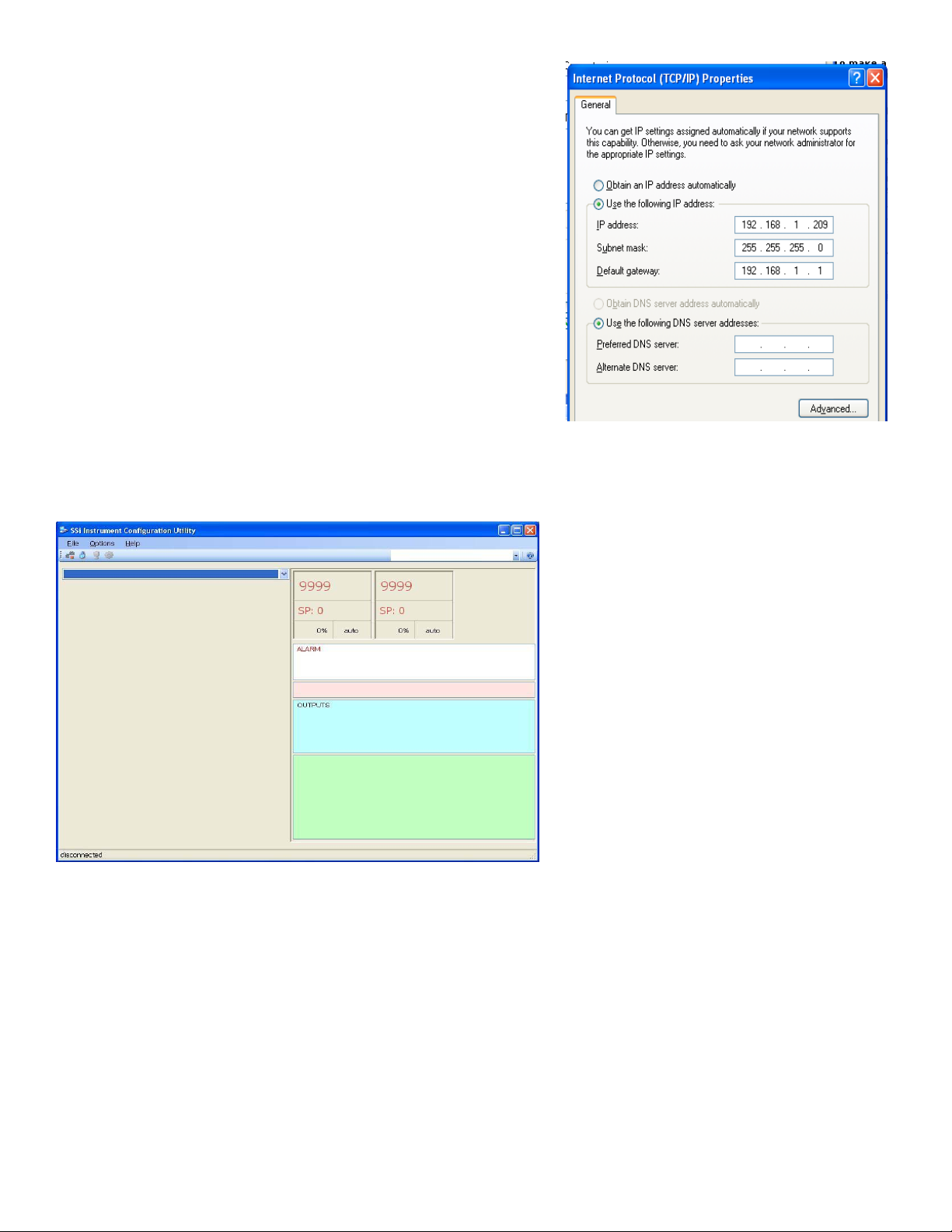
Enter in the following data on these fields:
IP Address: 192.168.0.209
Subnet Mask: 255.255.255.0
Default Gateway: 192.168.1.1
Note: These fields are suggestions. Contact your IT department to get
a valid IP address, Net Mask, and Gateway for the local computer.
To change the network settings on your computer you may need
addition information so please refer to the computer manual.
Step 3 – Configure Configurator 2.0 on the local computer
When Configurator starts up for the first time, the user will see the main screen, which will be blank because no
instruments have been set up yet. The first step is to set up an instrument in Configurator.
First, the user will need to log in with
administrative rights.
be logged in with at least administrative rights;
Supervisor rights will not allow the user to add an
instrument
Configurator are: operator, supervisor,
administrator, SSi Special. The lock on the
toolbar will let the user know what level is
currently logged in. Operators are blue,
supervisors are gold, administrators are green,
and the SSi Special, which is used for
configuration purposes before the unit is shipped,
is red. Click on the lock and log in with the
following information: username = administrator,
password = 2.
. The four levels of rights in
administrator passwords can be changed on the
Furnace Setup
be green. Click on the
Settings
Management
Click on the Add button to display the rest of the screen. First, give the instrument a name. The name can be anything
the user wants, but it is suggested that the user makes the name descriptive. Next, select the model from the drop-down
list. For the DAQ, the model number is “9021”. Next, enter the IP address in the “Ethernet” section and make sure the
“Ethernet” option is selected.
screen.
Note: The SSi DAQ is shipped with an IP address supplied by the customer
menu page
. This will display the
the local computer is hooked up directly to the instrument through a crossover cable, the IP address will still need to be
correct
the “Ethernet” IP address box. This will set up Configurator for Ethernet communications. To set it up for serial or
SuperData communications, the proper option will need to be selected and filled out.
. The user can also scan the network to find all available SSi instruments by clicking on the search button next to
Note: The user will need to
Note: The supervisor and
. The lock should now
Options
menu, then select
System
.
Note: even if
4576 DAQ Manual Revision A Page 8 Super Systems Inc
Page 9
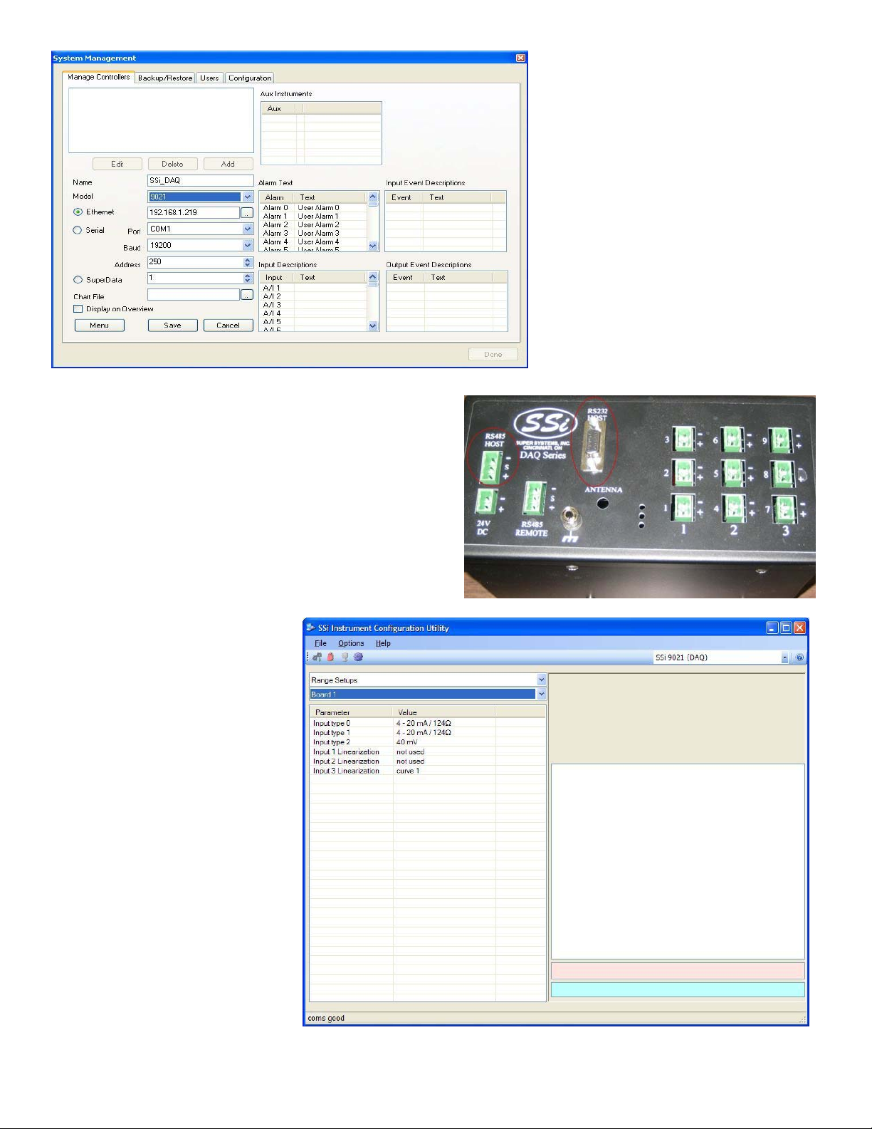
The DAQ has RS-232 host communications and RS-485 host communications capability (shown below). To set the DAQ
up for serial communications, the user will need to know which
COM port will be used. Select that COM port (COM 1 – COM
20 is available). The Baud rate can be left at the default –
19200. The address should be changed to 1. If the user is
using RS-232 communications, or if the DAQ is the only device
on RS-485 communications, then the address of 250 will be
sufficient.
Click on the Save button to save the information. Click on the
Done button to close down this screen.
The device can now be selected from the drop-down list on the
Configurator main screen.
Step 4 – Complete
Configurator Range
Setups Menu Option
Note: This menu item is also located
later in the manual under the
Configurator Menu
Range Setups
The
allow the user to view/modify the
selected input ranges for each of the
three inputs on a board. The user
will also be able to view/modify the
input linearization for each input per
board. There are a maximum of
sixteen boards.
The Input Type can be one of the
following:
B T
C 2.5 V
E 1.25 V
J 160 mV
K 80 mV
N 40 mV
NNM 20 mV
4576 DAQ Manual Revision A Page 9 Super Systems Inc
section
menu option will
.
Page 10

R 4-20 mA/124Ω
S 4-20 mA/62Ω
The Input Linearization can be one of the following:
Not Used
Curve 1
Curve 2
Curve 3
Curve 4
Curve 5
Curve 6
Curve 7
The “Input linearization” field is where the user can apply a specific curve, created with the menu option
to the input. To apply the curve, select the applicable curve, 1 through 7, from the drop-down list for the selected input.
Custom Curves
,
Step 5 – Complete Configurator
Input Offsets
Menu Option
Note: This menu item is also located
later in the manual under the
Configurator Menu
Input Offsets
The
allow the user to enter an offset for
each of the three inputs per board.
There can be a maximum of sixteen
boards. The offset can be within the
range of –32768 to 32767.
The decimal place will be dependent
on the input type selected from the
Range Setups
section
menu option will
menu
.
.
Note:
4576 DAQ Manual Revision A Page 10 Super Systems Inc
Page 11

AAnnaalloogg IInnppuuttss
The Super Systems, Inc. Part Number 31575 Analog Board contains a group of three channels isolated from the main DC
power source. Each input is fully isolated. The board can be connected to thermocouples, voltage sources from 20mV
full scale to 1.28 Volts full scale, voltage sources from 0 V full scale to 10 V DC full scale, or 4 – 20 mA current loops.
Adding a Jumper to an Input
When measuring a 4-20mA current signal or a
voltage signal, such as a thermocouple, a
jumper must be placed on the corresponding
two or three-position header. For example,
Input 1 would need to have a jumper placed
between the pins labeled “I1” before
connecting a 4-20mA signal. Failure to add
the jumper will result in damage to the circuit
board. The jumper may already be present at
each of the three headers, but unless it is
attached across both pins (not just one) it will
not be connected.
Thermocouple connections
Thermocouple wires can be connected directly to the terminal blocks. The thermocouple junctions should not be
grounded. If they do touch a ground reference, all thermocouples on a board must have a common ground reference. If
multiple thermocouples are connected to different ground reference points, the accuracy of all thermocouples on the
board cannot be guaranteed to be accurate. When setting up a voltage input signal, such as a thermocouple input or any
voltage input signal up to 1.28 volts, the jumper must be placed on the pins in the 1:1 setup (left diagram).
Voltage connections
Voltages from 0 mV to 10 Volts DC can be directly connected to the terminal blocks. When measuring ground-referenced
voltages, all references must share a common ground reference. If the voltage sources are connected to different ground
reference points, the accuracy of all the voltage sources connected to the board need to be checked for accuracy.
Since
higher voltages can damage the input board, any voltage input signals, such as a vacuum gauge,
must have the jumpers placed on the pins in the 10:1 setup (middle diagram)
any signal going into the board will be scaled down so it will not damage the input board.
4576 DAQ Manual Revision A Page 11 Super Systems Inc
. This will insure that
Page 12

4 – 20 mA. Current Loop connections
Before connecting the current loop, insert the shorting jumper on the board for each channel used to measure current
loops. This jumper inserts the 62-ohm shunt resistor across the input of the A/D. If multiple current loops are connected
to one board, all must share the same power supply and ground reference points or the accuracy of all the current loops
need to be checked for accuracy. When setting up a current input signal, such as a 4 – 20 mA signal, the jumper must
be placed on the pins in the current setup (right diagram). Notice that there is also a jumper set up in the 1:1 setup only
when inputting a current signal. This is because current signals also have a corresponding voltage signal.
Warning: Connecting a mA input without the Input Jumper will damage the
input.
To add a jumper to an input:
1. Power down the unit.
2. Remove the thermocouple connector and the Ethernet cable from the DAQ.
3. Remove the top plate of the DAQ by unscrewing the screws around the top of the DAQ.
4. Grasping both sides of the input board, carefully pull the input board out of the DAQ and set the jumper for the
appropriate set of pins, i.e. “V1” for input 1, “V2” for input 2, etc.
– to be considered “on”. Slide the input board back into the DAQ slot.
5. Replace the top plate of the DAQ by screwing in the screws around the top of the DAQ.
6. Re-connect the Ethernet cable and thermocouple connector.
Setting the DIP switches to Assign Board Numbers
DIP switch has four switches on it labeled: 1, 2, 3, and 4. These numbers follow a binary numbering system – i.e. 1 = 1,
2 = 2, 3 = 4, and 4 = 8. There is an ON and an OFF position for each switch. OFF = 0 and ON = 1. Each board number
can be assigned by setting the appropriate switches to ON. For example, to set a board number to 1, set the “1” switch
to ON and the “2”, “3”, and “4” switches to OFF ((1*1) + (2*0) + (4*0) + (8*0) = 1). To set the board number to 10,
set the “1” and “3” switches to OFF and the “2” and “4” switches to ON ((1*0) + (2*1) + (4*0) + (8*1) = 10).
Turning all switches to the off position sets the board to address 16
A jumper will need to be set – placed on both pins
Each input board, whether directly
connected in the DAQ or connected
through a satellite box, must have a
unique address assigned by the DIP
switches on each input board. A unique
address will ensure that the DAQ will
correctly read all of the boards set up. If
two or more boards have the same
address, multiple errors could occur such
as: DAQ reading data from one board one
second, then reading data from another
board the next second, no data being read
from the DAQ, etc.
each board has a unique address
It is important that
. Each
Note:
.
4576 DAQ Manual Revision A Page 12 Super Systems Inc
Page 13

CCoonnffiigguurraattoorr MMeennuu
Input Values
The
Input Values
display the current values of the inputs
for each board up to sixteen boards,
with three inputs per board. This screen
is a read-only screen. See
Input Number Table
the input numbering.
menu option will
Appendix 1 –
for a description on
4576 DAQ Manual Revision A Page 13 Super Systems Inc
Page 14
Aux Instruments
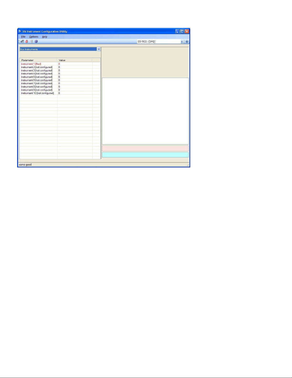
The
Aux Instruments
will display the auxiliary instruments
and their current values (if
configured). This screen is a readonly screen. See the
section for information on
Setup
setting up an auxiliary instrument.
menu option
Aux Instrument
4576 DAQ Manual Revision A Page 14 Super Systems Inc
Page 15

Communication Setup
The
Communication Setup
option will allow the user to set up
the communications parameters for
the DAQ.
Host 232 Baud
This option will allow the user to set
the Host 232 baud rate. The options
are:
1200
2400
4800
9600
14400
19200
28800
38400
57600
76800
115200
Slave 232 Baud
This option will allow the user to set
the Slave 232 baud rate. The
options are:
1200 19200 115200
2400 28800
4800 38400
9600 57600
14400 76800
Host 485 Baud
This option will allow the user to set the Host 485 baud rate. The options are:
1200 19200 115200
2400 28800
4800 38400
9600 57600
14400 76800
Host 485 Address
This option will allow the user to set the Host 485 address. The range is 1 through 249.
Slave 1 (5,6) Baud
This option will allow the user to set the Slave 1 baud rate. The options are:
1200 19200 115200
2400 28800
4800 38400
9600 57600
14400 76800
Slave 1 (5,6) Mode
This option will allow the user to set the Slave 1 mode. The options are: Modbus or Modbus Host
IP Address/IP Mask/IP Gateway
menu
4576 DAQ Manual Revision A Page 15 Super Systems Inc
Page 16

These options will allow the user to change the various IP addresses of the DAQ. Contact Super Systems Inc at 800-666-
4330 or your IT department for help in changing any of these addresses.
Note: Once the IP address has been changed, communications with the
DAQ will be lost until the correct IP address is entered on the
Management
computer
user to change all of the options at once.
screen (
section above)
Step 3 – Configure Configurator 2.0 on the local
. Clicking on any of these options will allow the
System
4576 DAQ Manual Revision A Page 16 Super Systems Inc
Page 17

Device Configuration
The
Device Configuration
allow the user to change certain
configuration options on the DAQ.
Currently, the only option to change is the
Temperature Mode option.
Temperature Mode
This option will allow the user to change
the mode of the temperature. The
options are ◦F or ◦C.
menu option will
4576 DAQ Manual Revision A Page 17 Super Systems Inc
Page 18

Range Setups
The
Range Setups
allow the user to view/modify the
selected input ranges for each of the
three inputs on a board. The user
will also be able to view/modify the
input linearization for each input per
board. There are a maximum of
sixteen boards.
The Input Type can be one of the
following:
B T
C 2.5 V
E 1.25 V
J 160 mV
K 80 mV
N 40 mV
NNM 20 mV
R 4-20 mA/124Ω
S 4-20 mA/62Ω
The Input Linearization can be one
of the following:
Not Used
Curve 1
Curve 2
Curve 3
Curve 4
Curve 5
Curve 6
Curve 7
The “Input linearization” field is where the user can apply a specific curve, created with the menu option
to the input. To apply the curve, select the applicable curve, 1 through 7, from the drop-down list for the selected input.
menu option will
Custom Curves
,
4576 DAQ Manual Revision A Page 18 Super Systems Inc
Page 19

Input Offsets
The
Input Offsets
allow the user to enter an offset for
each of the three inputs per board.
There can be a maximum of sixteen
boards. The offset can be within
the range of –32768 to 32767.
Note: The decimal place will be
dependent on the input type
selected from the
.
menu
menu option will
Range Setups
4576 DAQ Manual Revision A Page 19 Super Systems Inc
Page 20

Aux Instrument Setup
The
Aux Instrument Setup
menu option will allow the user
to set up the auxiliary
instruments for the DAQ. This
screen will list the instruments
available for setup, and any
configurations set on the
instruments.
Instrument
The list of available instruments are:
SSi AC20/7EK/20Q/20PQ
SSi 7SL
9200 LP 1
9200 LP 2
9200 LP 3
AE Flow_Meter
Eur 2404, E2704 LP1
Eur 2500 LP 1
Eur 2500 LP 2, E2704 LP 2
E2704 LP3
UDC 3300
Yoko UT320, UT350
Yoko UP350
Yoko 550 LP 1, 750 LP 1
Yoko 550, 750 LP 2
Address
The address can be 0 to 249.
Note: An address of 0 disables the slave instrument on the DAQ
.
Note: There are twenty-six auxiliary instruments to set up on this menu screen, but only ten auxiliary instruments listed
on the
the internal memory locations of the input boards, starting with board 16: Aux instrument 11 replaces board 16; aux
instrument 12 replaces board 15, etc.
Aux Instruments
menu screen
. Starting with aux instrument 11, the values for the aux instrument begin taking up
4576 DAQ Manual Revision A Page 20 Super Systems Inc
Page 21

Custom Curves
The
Custom Curves
the user to set up the variables for the
curves. Curves are applied when the user
wants to use a non-linear compensation to
the input, such as in vacuum areas.
There are a maximum of seven curves.
The Interpolation Type can be one of
the following:
None
Linear
The mV 1 through mV 32 can be within
the range of –32768 to 32767.
The Offset 1 through Offset 32 can be
within the range of –32768 to 32767.
Note: This is where the user will create
the custom curve that can be applied to
the inputs through the
menu option
section for information on how to apply a
curve to an input.
An example of a non-linear curve is for a
0 to 1V span (0 to 1000 mV). If the mV is 0, then the offset is 0. If the mV is 200, then the offset if 400, etc.
. See the
menu option will allow
Range Setups
Range Setups
4576 DAQ Manual Revision A Page 21 Super Systems Inc
Page 22

Calibration
The
Calibratio
calibrate the inputs on a board. Click on the click
value to begin the calibration process.
The user will need a thermocouple calibrator
capable of outputting a thermocouple signal to
calibrate the zero, span or cold junction value of
the analog input board. The user will need to
connect the calibrator to one of the inputs on the
board that will be calibrated. It is recommended to
let everything (calibrator and input board) sit for
approximately thirty minutes to allow the
temperature to achieve equilibrium. Set up the
calibrator for the specific thermocouple type of the
thermocouples in the analog input board, i.e. type
K, type J, etc. Then, source a specific temperature,
like 1000 °F, or millivolt to the connected input. It
is recommended that the actual temperature used
be similar to an appropriate process temperature.
For example, if your equipment normally operates
at 1700 °F, then perform the cold junction calibration using a 1700 °F signal. It is important to note that when
performing a zero or span calibration,
wire, or even regular copper wire. To perform the calibrations, the user will need a calibrator that is capable of
outputting volts, millivolts, and temperature.
Below is a listing of the suggested ranges for the various TC types.
n menu option will allow the user to
do not use
TC Type mV Range Chart
TC Type
regular thermocouple wiring. Instead, use any kind of regular sensor
Range in mV
B 20
C 40
E 80
J 80
K 80
N 80
NNM 80
R 40
S 20
T 20
Zero/Span Calibration
The first step in the calibration process is the zero and
span calibration. To select a board to calibrate, click on
the Select button. This will display a drop-down list that
the user can select the board to calibrate. This list will
only display the available boards to calibrate. Once a
board is selected, the current values will be displayed
along the right of the tab box. Select the input range from
the drop-down list. To perform a zero calibration, select
the “Zero” option. To perform a span calibration, select
the “Span” option. The target value for a zero calibration
is 0 millivolts. The target value for a span calibration is
roughly ninety percent of the range millivolts. The target
value is displayed in the box and can be modified, if desired. If the millivolt range is not known, the user can click on the
help button next to the range drop-down list. This will display a list of inputs. Selecting the correct input will set the
correct millivolt range.
Checking the check box next to the corresponding input will determine if that input will be included in the calibration.
4576 DAQ Manual Revision A Page 22 Super Systems Inc
Page 23

Note: If the user is using a 10:1 jumper, the user will need to multiply the source
signal by 10 to get the correct span value
on a 1.25V range, the suggested source signal will read 1000 mV. The supplied
signal will need to be 10000 mV to account for the 10:1 jumper.
For a zero calibration, a value of 0 mV will need to be sourced to the input or
inputs.
For a span calibration, a value of 90 % of the full range will need to be sourced to
the input or inputs.
Press the Calibrate button to begin the calibration process.
Press the Set Nominal button to apply nominal values to the inputs.
. For example, if the 10:1 jumper is set
Cold Junction Offset
The second step in the
calibration process is setting
the cold junction offset. If
necessary, select a board to calibrate by clicking on the Select
button. This will display a drop-down list that the user can select
the board to calibrate. This list will only display the available boards
to calibrate. Select the board’s input to apply the cold junction
offset to by using the up and down arrows. Select the appropriate
offset to use by using the up and down arrows. This can range from
-25.00 to 25.00.
junction value, be sure to set the offset value as a minus value by clicking on the plus/minus key on the keypad (+/-)
The overall Cold Junction value is modified by adding or subtracting a value to the current value.
button to begin the calibration process.
Press the Done button to close out the screen.
Note – To subtract a value from the current cold
Press the Calibrate
.
4576 DAQ Manual Revision A Page 23 Super Systems Inc
Page 24

SSaatteelllliittee BBooxxeess –– SSRR33,, SSRR66
The satellite boxes, P/N 13475 (SR3) or 13476 (SR6), represent expandable input slots for the Video Recorders which can
be mounted remotely and connected back to the main Video Recorder unit using the RS485 ports. These satellite boxes
will give customers the ability to add inputs to the Video Recorder.
The SR3 (pictured) contains three additional inputs for
the Video Recorder.
The satellite box SR6 contains six additional inputs for the
Video Recorder.
To connect the satellite box back to the main Video
Recorder unit, the “Remote RS485” on the satellite box
must be wired into the “RS485 Remote” on the main unit.
24VDC need to be provided to the satellite box either by
using a jumper from the main VR unit or from a separate
source.
4576 DAQ Manual Revision A Page 24 Super Systems Inc
Page 25

DDAAQQ DDaattaa SShheeeettss
Serial Number
IP Address
Description
Number of Boards Used
Notes
Board # Input # Input Type Furnace Description Curve
1 1 (1)
2 (2)
3 (3)
2 1 (4)
2 (5)
3 (6)
3 1 (7)
2 (8)
3 (9)
4 1 (10)
2 (11)
3 (12)
5 1 (13)
2 (14)
3 (15)
6 1 (16)
2 (17)
3 (18)
7 1 (19)
2 (20)
3 (21)
8 1 (22)
2 (23)
3 (24)
4576 DAQ Manual Revision A Page 25 Super Systems Inc
Page 26

Serial Number
IP Address
Description
Board # Input # Input Type Furnace Description Curve
9 1 (25)
2 (26)
3 (27)
10 1 (28)
2 (29)
3 (30)
11 1 (31)
2 (32)
3 (33)
12 1 (34)
2 (35)
3 (36)
13 1 (37)
2 (38)
3 (39)
14 1 (40)
2 (41)
3 (42)
15 1 (43)
2 (44)
3 (45)
16 1 (46)
2 (47)
3 (48)
4576 DAQ Manual Revision A Page 26 Super Systems Inc
Page 27

AAppppeennddiixx 11 –– IInnppuutt NNuummbbeerr TTaabbllee
The
Input Values
than the board input number. For instance, Board 1 has input 1, input 2, and input 3. Board 2 also has input 1, input 2,
and input 3. However, each of the inputs also has an absolute number that will range from 1 to 48. For instance, Board
1’s absolute input numbers are input 1, input 2, and input 3. But, Board 2’s absolute input numbers are input 4, input 5,
and input 6. Below is a table listing the board numbers, input numbers, and absolute input numbers.
Board #
1 1 1 9 1 25
2 2 2 26
3 3 3 27
2 1 4 10 1 28
2 5 2 29
3 6 3 30
3 1 7 11 1 31
2 8 2 32
3 9 3 33
4 1 10 12 1 34
2 11 2 35
3 12 3 36
5 1 13 13 1 37
2 14 2 38
3 15 3 39
6 1 16 14 1 40
2 17 2 41
3 18 3 42
7 1 19 15 1 43
2 20 2 44
3 21 3 45
8 1 22 16 1 46
2 23 2 47
3 24 3 48
Input # Absolute Input # Board # Input # Absolute Input #
menu screen (
Configurator Menu
section) displays the boards with the absolute input number, rather
4576 DAQ Manual Revision A Page 27 Super Systems Inc
Page 28

AAppppeennddiixx 22 -- IInnppuutt RRaannggeess
Input Type Minimum Maximum
B 32 ◦F 3308 ◦F
C 32 ◦F 4208 ◦F
E -328 ◦F 1832 ◦F
J -346 ◦F 2192 ◦F
K -328 ◦F 2502 ◦F
N -328 ◦F 2372 ◦F
NNM 0 ◦F 1409 ◦F
R -58 ◦F 3214 ◦F
S -58 ◦F 3214 ◦F
T -328 ◦F 752 ◦F
2.56 V -25600 25600
1.28 V -12800 12800
160 mV -16000 16000
80 mV -8000 8000
40 mV -4000 4000
20 mV -20000 20000
4 – 20 mA / 124Ω
Using 1:1 jumper
4 – 20 mA / 124Ω
Using 10:1 jumper
4 – 20 mA / 62Ω
Using 1:1 jumper
4 – 20 mA / 62Ω
Using 10:1 jumper
*** The 4 – 20 mA / 124Ω option is used mainly with the five input boards
*** The 4 – 20 mA / 62Ω option is used mainly with the three input boards
2000 10000
200 1000
4000 20000
400 2000
4576 DAQ Manual Revision A Page 28 Super Systems Inc
Page 29

RReevviissiioonn HHiissttoorryy
Rev. Description Date MCO #
- Initial Release 7/29/2008 N/A
A Changed picture formatting to allow text to wrap around; Added “Aux
Instruments”, “Communication Setup”, “Device Configuration”, “Aux Instrument
Setup” Configurator menus; Modified “Range Setups” Configurator menu; Added
sample curve in “Custom Curves” section; Added serial communications setup
12/4/2008 2071
instructions
4576 DAQ Manual Revision A Page 29 Super Systems Inc
 Loading...