


SUPER
AOC-SOZCR1
AOC-LPZCR1
AOC-LPZCR1/AOC-SOZCR1
All-In-One ZCR Card
USER'S GUIDE
Rev. 1.0a


 AOC-LPZCR1/AOC-SOZCR1 User's Guide
The information in this User’s Guide has been carefully reviewed and is believed to be accurate. The vendor assumes no responsibility for any inaccuracies that may be contained in this document, makes no commitment to update or to keep current the information in this manual, or to notify any person or organization of the updates. Please Note: For the most up-to-date version of this manual, please see our web site at www.supermicro.com.
SUPERMICRO COMPUTER reserves the right to make changes to the product described in this manual at any time and without notice. This product, including software, if any, and documentation may not, in whole or in part, be copied, photocopied, reproduced, translated or reduced to any medium or machine without prior written consent.
IN NO EVENT WILL SUPERMICRO COMPUTER BE LIABLE FOR DIRECT, INDIRECT, SPECIAL, INCIDENTAL, OR CONSEQUENTIAL DAMAGES ARISING FROM THE USE OR INABILITY TO USE THIS PRODUCT OR DOCUMENTATION, EVEN IF ADVISED OF THE POSSIBILITY OF SUCH DAMAGES. IN PARTICULAR, THE VENDOR SHALL NOT HAVE LIABILITY FOR ANY HARDWARE, SOFTWARE, OR DATA STORED OR USED WITH THE PRODUCT, INCLUDING THE COSTS OF REPAIRING, REPLACING, INTEGRATING, INSTALLING OR RECOVERING SUCH HARDWARE, SOFTWARE, OR DATA.
Any disputes arising between manufacturer and customer shall be governed by the laws of Santa Clara County in the State of California, USA. The State of California, County of Santa Clara shall be the exclusive venue for the resolution of any such disputes. Supermicro's total liability for all claims will not exceed the price paid for the hardware product.
Unless you request and receive written permission from SUPER MICRO COMPUTER, Inc., you may not copy any part of this document.
Information in this document is subject to change without notice. Other products and companies referred to herein are trademarks or registered trademarks of their respective companies or mark holders.
Copyright © 2005 by SUPER MICRO COMPUTER, INC.
All rights reserved.
Printed in the United States of America
1-2

Chapter 1: Introduction
Table of Contents
Chapter I: Introduction............................................................................. |
1-4 |
||
|
1.1 |
Overview ................................................................................................. |
1-4 |
|
1.2 |
Introduction to SATA and SAS ............................................................. |
1-4 |
|
1.3 |
Product Features.................................................................................... |
1-4 |
|
1.4 |
Contacting Supermicro ......................................................................... |
1-6 |
|
1.5 |
Product Compliance Information ......................................................... |
1-6 |
Chapter 2: Technical Specifications and Software Installation........... |
2-1 |
||
|
2.1 AOC-LPZCR1 Card Layout and Jumper Locations ............... |
2-1 |
|
|
2.1.1 AOC-LPZCR1 Card Layout and Jumper Locations ................................ |
2-1 |
|
|
2.1.2 Jumper and Connector Descriptions (*AOC-LPZCR1) ........................... |
2-2 |
|
|
2.1.3 Jumpers and LED Indicators (*AOC-LPZCR1) ...................................... |
2-3 |
|
|
2.2 |
AOC-SOZCR1 Card Layout and Header Locations ............... |
2-4 |
|
2.2.1 AOC-LPZCR1 Card Layout and Jumper Locations ................................ |
2-4 |
|
|
2.2.2 Connector and Header Descriptions (*AOC-SOZCR1)........................... |
2-5 |
|
|
2.2.3 SMB Connector and Pin Defi nitions (*AOC-SOZCR1) ........................... |
2-5 |
|
|
2.3 |
Intelligent Interface Management: SAF-TE .......................................... |
2-6 |
|
2.4 |
Safety Guidelines ................................................................................... |
2-7 |
|
2.5 |
Installing the Controller Driver ............................................................ |
2-8 |
|
2.5.1 Creating the Driver Floppy Disk............................................................. |
2-8 |
|
|
2.5.2 Adding the Driver into an Existing System.............................................. |
2-8 |
|
|
2.5.3 Installing the Driver into a New System.................................................. |
2-9 |
|
Chapter 3: RAID Configuration................................................................ |
3-1 |
||
|
3.1 |
Using Adaptec's Array Configuration Utility ....................................... |
3-3 |
|
3.2.1 Using Adaptec's SCSISelect Utility ....................................................... |
3-18 |
|
|
3.2.2 Using Adaptec's SATASelect Utility....................................................... |
3-21 |
|
|
3.2.3 Using Adaptec's Serial_Select Utility..................................................... |
3-22 |
|
|
3.2.4 Using Physical Confi guration Utility ...................................................... |
3-24 |
|
3.3 |
Using Disk Utilities........................................................................................ |
3-23 |
|
|
3.3.1 Using Disk Utilities (*for SCSI only) ...................................................... |
3-23 |
|
|
3.3.2 Using Disk Utilities (*for SATA/SAS only) ............................................. |
3-24 |
|
|
|
3.3.2.1 To Format a Disk Drive .............................................................. |
3-24 |
|
|
3.3.2.2 To Verify Disk Media .................................................................. |
3-25 |
|
3.3 |
To Exit the Adaptec Array Configuration Utility .............................. |
3-25 |
Chapter 4: Troubleshooting ..................................................................... |
4-1 |
||
1-3


 AOC-LPZCR1/AOC-SOZCR1 User's Guide
Chapter 1 Introduction
This manual is written for system integrators, PC technicians and knowledgeable PC users who intend to integrate Supermicro's Zero-Channel RAID solution into their RAID system. It provides detailed information for the installation and use of the AOC-LPZCR1/AOC-SOZCR1 All-In-One card that supports SAS/ SATA/SCSI confi gurations in a slim-size card. The Supermicro AOC-LPZCR1/AOC- SOZCR1 offers an innovative, complete and cost effective solution to the ever-in- creasing demands of disk density and data integrity of today's servers.
1.1 Overview
The AOC-LPZCR1/AOC-SOZCR1 is a highly effi cient, highly compatible and easy- to-use SAS/SATA/SCSI RAID Controller that allows the user to confi gure RAID 0, RAID 1, RAID 5, RAID 10 and JBOD by using Marvell's 88SX6041/-6081 (Hercules II), Adaptec's AIC-7901/-7902 Ultra 320 SCSI Controller or Adaptec's AIC-9410 SAS Controller on the motherboard. With the built-in Intel's Verde 400 MHz I/O Processor and 64 MB ECC DDR memory, the AOC-LPZCR1/AOC-SOZCR1 supports PCI- X speeds up to 100MHz and provides the user with a high-speed, space-saving, scalable and intelligent hardware RAID solution.
1.2 Introduction to SATA (Serial ATA) and SAS (Serial Attached SCSI)
Serial ATA(SATA) is a physical storage interface. It uses a single cable with a minimum of four wires to create a point-to-point connection between devices. It is a serial link which supports SATA transfer rates from 150MBps. Because the serial cables used in SATA are thinner than the traditional cables used in Parallel ATA (PATA), SATA systems provide more effi cient system cooling, faster data transfer and better functionality than Parallel ATA.
With the functionality provided by the onboard SAS controller, the AOC-LPZCR1/ AOC-SOZCR1 offers unprecedented I/O throughput, reliability and scalability to the IT industry. In addition, with a dynamic serial-link transmission infrastructure built-in, the AOC-LPZCR1/AOC-SOZCR1 supports both SATA and SAS without any bridging, providing the user with unparalleled data storage expansion and inter-connectivity capability.
1.3 Product Features
(1) The AOC-SOZCR1 Series: (the Terminator Socket DIMM ZCR
CARD):
•Slim design: pocket-size (3.2" H x 3.8" W)
•Intel's Verde I/O Processor @ 400MHz built-in
•64 MB onboard ECC DDR memory
•1 amp@ 3.3V
1-4

Chapter 1: Introduction
•Supports Marvell's Hercules II 88SX6081 (8-port)/88SX6041 (4-port) Host Controller
•Supports Adaptec's AIC-7901/-7902 Ultra 320 SCSI Controller and AIC-9410 SAS Controller
•RAID 0, RAID 1, RAID 5, RAID 10, RAID 50* and JBOD supported (*See Note 1 Below.)
(2) The AOC-LPZCR1 Series: (-Low Profile Skyhawk ZCR RAID Card)
•Low profi le Form Factor (2.5" H x 6.6" W)
•Intel's IOP321 I/O Processor (Verde) @ 400MHz built-in
•64 MB onboard ECC DDR memory
•1 amp@ 3.3V
•RAID 0, RAID 1, RAID 5, RAID 10, RAID 50* and JBOD supported (*See Note 1 Below.)
(a) SAS (-based on the Adaptec AIC-9410 Host Controller)
•Supports Adaptec's AIC-9410 SAS Host Controller
•Supports PCI-X up to 100 MHz in the green slot (*See Note 2)
(b)SATA (-based on the Marvell Hercules II Controller)
•Supports Marvell's Hercules II 88SX6081 (8-port) or 88SX6041 (4-port) Host Controller
•Supports PCI-X slot up to 100MHz in the green slot (*See Note 2)
(c) SCSI (-based on the Adaptec AIC-7901 or AIC-7902Ultra 320 SCSI Controller)
•Supports Adaptec's AIC-7901/-7902 Ultra 320 SCSI Controller
•Supports PCI-X up to 100 MHz in the green slot (*See Note 2)
Operating Systems supported
*Windows 2000, Windows XP, and Windows 2003
*Linux: SuSE 9.0, SuSE 9.1, SuSE 9.2, Red Hat 3.0 and Red Hat 4.0
*Upgradable in the future.
Management support
*Adaptec's Storage Manager
*Adaptec Flash Utility
*Adaptec RAID Confi guration Utility
*SAF-TE (*SCSI and SATA only)
Key RAID Features
*RAID detection, confi guration, deletion, addition, and error detection
*Background initialization
*Hot-spare disk drive support for easy replacement
*Hot-spare disk drive support with automatic rebuild
(*Notes: |
Note 1: |
RAID 50 is available for SAS only. |
|
Note 2: |
Please install the ZCR card in the green slot.) |
|
|
|
1-5


 AOC-LPZCR1/AOC-SOZCR1 User's Guide
1.4 Contacting Supermicro
Headquarters
Address: |
SuperMicro Computer, Inc. |
|
980 Rock Ave. |
|
San Jose, CA 95131 U.S.A. |
Tel: |
+1 (408) 503-8000 |
Fax: |
+1 (408) 503-8008 |
Email: |
marketing@supermicro.com (General Information) |
|
support@supermicro.com (Technical Support) |
Web Site: |
www.supermicro.com |
Europe
Address: |
SuperMicro Computer B.V. |
|
Het Sterrenbeeld 28, 5215 ML |
|
's-Hertogenbosch, The Netherlands |
Tel: |
+31 (0) 73-6400390 |
Fax: |
+31 (0) 73-6416525 |
Email: |
sales@supermicro.nl (General Information) |
|
support@supermicro.nl (Technical Support) |
|
rma@supermicro.nl (Customer Support) |
Asia-Pacific
Address: |
SuperMicro, Taiwan |
|
4F, No. 232-1 Liancheng Road |
|
Chung-Ho 235, Taipei Hsien, Taiwan, R.O.C. |
Tel: |
+886-(2) 8226-3990 |
Fax: |
+886-(2) 8226-3991 |
Web Site: |
www.supermicro.com.tw |
Technical Support: |
|
Email: |
support@supermicro.com.tw |
1.5 Product Compliance Information
The AOC-LPZCR1/AOC-SOZCR1 is compliant with the following product standards/requirements:
* USA: |
FCC 47 CFR, Part 15, subpart B |
* European Union: |
EN 55022 |
|
EN 55024 |
1-6
Chapter 2: Technical Specifi cations and Installation
Chapter 2
Technical Specifications and Software
Installation
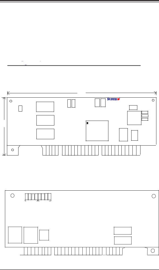
2.1 AOC-LPZCR1 Card Layout and Jumper Locations
2.1.1  AOC-LPZCR1 Card Layout and Jumper
Locations
Front view (AOC-LPZCR1)
J4
2.5”
Buzzer |
Connector |
Cache
Cache
Cache
7.0”
5V LED DS14 |
DS13 |
3V LED |
Flash Firmware |
|
|
AOC-LPZCR1 Rev. 1.01 |
|
J6 |
J2 Act. |
J1 I2C |
|
||||
|
|
|
|
|
|
|
J7 |
|
|
|
|
|
|
CPLD |
J5 |
|
|
|
|
|
|
J3 |
|
|
|
|
|
|
|
|
|
I/OProcessor |
|
Flash EPROM |
NVS RAM |
SAS
SATA2 SCSI
Rear view
DS 8 |
DS 7 |
DS 6 |
DS 5 |
DS 4 |
DS12 DS11 |
DS10 |
Diag.LED Diag.LED
Flash EPROM
SRAM
Cache
Cache
Flash EPROM
2-1


 AOC-LPZCR1/AOC-SOZCR1 User's Guide
2.1.2 Jumper and Connector Descriptions (*AOC-LPZCR1)
Jumper |
|
Description |
|
J2 |
|
Activity LED Connector |
(*See 2.1.3 for details) |
J4 |
|
Buzzer Connector |
(*See 2.1.3 for details) |
Connector |
|
Description |
J1 |
|
Systerm Management Bus (I2C) (*See I2C cable |
|
|
connection on the next page.) |
J3 |
|
SCSI Mode (On: Enable) |
J5 |
|
Serial ATA Mode (SATA 2) Mode (On: Enable) |
J6 |
|
Flash Firmware (On: Flashing Firmware) |
J7 |
|
SAS Mode (On: Enable) |
(DS10-12, DS4),(DS5-8)Diagnostic LED Indicators
2-2
Chapter 2: Technical Specifi cations and Installation
2.1.3 Connectors and LED Indicators (*AOC-LPZCR1)
Activity LED Indicator
Activity LED Indicator (J2), located on the front side of the AOC-LPZCR1 card, indicate the activity status of the AOC-LPZCR1 card. See the table on the right for pin defi nitions.
Activity LED
Pin Definitions (J2)
Pin# |
Pin Definitions |
Pin1 |
-(Negtive) or Cathod |
Pin2 |
+(Positive) or Anode |
|
|
Buzzer Connector
Buzzer Connector (J4), located on the front side of the AOC-LPZCR1 card, provides a connection for the onboard buzzer. See the table on the right for pin defi nitions.
Buzzer Connector
Pin Definitions (J4)
Pin# Definitions
Pin1 +(Positive) Pin2 -(Negtive)
SMB (I2C)
A System Management Bus header is located at J1. Connect the I2C cable here to utilize SMB on your add-on card (*See below). See the table on the right for pin defi nitions.
I2C Cable Connection
SMB (I2C)
Pin Definitions (J1)
Pin
Number Definition
1Data
2Ground
3Clock
3-Pin Connector (J1) |
3-Pin Connector |
on the LPZCR1 |
on the cable |
1.The I2C Cable has a 3-pin connector on one end, and a 4-pin connector on the other end.
2.Connect the 3-pin connector of the cable to the 3-pin I2C Connector (J1) on the AOC-LPZCR card as shown on the right.
|
4-Pin I2C Connector |
4-Pin Connector on |
|
3. Connect the 4-pin connector of |
on the Backplane |
||
the cable |
|||
|
|
||
the cable to the 4-pin I2C Connector |
|
|
|
on the backplane as shown on the |
|
|
|
right. |
|
|
(*Note: Refer to the layout on Page 2-1 for the locations of the Connectors and LED Indicators.
2-3


 AOC-LPZCR1/AOC-SOZCR1 User's Guide
2.2.1  AOC-SOZCR1 Card Layout and Jumper
Locations
2.2 AOC-SOZCR1 Card Layout and Jumper Locations
Front view (AOC-SOZCR1)
|
|
|
|
|
3.19" |
|
|
|
|
|
Flash Firmware |
J6 |
AOC-SO ZCR1 |
|
|
|
|
|
||
|
|
|
|
|
|
|
|
SAS |
J 4 |
Cache |
|
Cache |
Flash EPROM |
|
SATA 2 |
J 3 |
|
|||
|
SCSI |
J 2 |
|
|||
|
|
|
|
|
||
|
C |
|
|
|
|
|
3.82" |
2 |
|
|
|
|
|
I |
|
|
|
|
|
|
|
|
|
|
|
|
|
|
|
J1 |
|
|
|
|
|
|
|
|
Pin 1 |
NVSRAM |
|
|
|
|
|
|
I/O Processor |
|
|
|
|
|
|
|
|
|
|
|
|
|
|
U6 |
|
|
|
|
|
2.66" |
|
Rear view (AOC-SOZCR1)
3.19"
Flash
Cache |
Cache |
Cache |
3.82"
Flash EPROM
2.66" |
2-4
Chapter 2: Technical Specifi cations and Installation
2.2.2 Connector and Header Descriptions (*AOC-SOZCR1)
Connector |
|
Description |
J1 |
|
Systerm Management Bus (I2C) (*See Page 2-2 for |
|
|
I2C cable connection.) |
J2 |
|
SCSI Mode (On: Enable) |
J3 |
|
Serial ATA (SATA2) Mode (On: Enable) |
J4 |
|
SAS Mode (On: Enable) |
J6 |
|
Flash Firmware (On: Flashing Firmware.) |
2.2.3 SMB Connector and Pin Definitions (*AOC-SOZCR1)
SMB (I2C) |
|
|
|
|
|
|
|
|
|
|
|
SMB (I2C) |
|
|
|
||
|
|
|
|
|
|
|
||
A System Management Bus header is |
|
|
Pin Definitions (J1) |
|
|
|
||
located at J1. Connect the I2C cable |
|
|
|
|
|
|
|
|
|
|
Pin |
Definition |
|
|
|
||
here to utilize SMB on your add-on |
|
|
Number |
|
|
|
||
|
|
1 |
|
Data |
|
|
|
|
card (*See below). See the table on |
|
|
2 |
Ground |
|
|
|
|
|
|
3 |
|
Clock |
|
|
|
|
|
|
|
|
|
|
|
||
the right for pin defi nitions. |
|
|
|
|
|
|
|
|
|
|
|
|
|
|
|
||
I2C cable Connection |
3-Pin Connector (J1) on |
3-PinConnector on |
||||||
|
the cable |
|||||||
|
|
|
the SOZCR1 |
|
||||
1.The I2C Cable has a 3-pin connector on one end, and a 4-pin connector on the other end.
2.Connect the 3-pin connector of the cable to the 3-pin I2C Connector (J1) on the AOC-SOZCR1 card.
3.Connect the 4-pin connector of the cable to the 4-pin I2C Connector on the backplane as shown on the right.
4-Pin I2C Connector |
4-Pin Connector on |
on the Backplane |
the cable |
*Note 1: Refer to the layout on Page 2-4 for the locations of the Connectors and LED Indicators.
2-5


 AOC-LPZCR1/AOC-SOZCR1 User's Guide
2.3 Intelligent Interface Management: SAF-TE
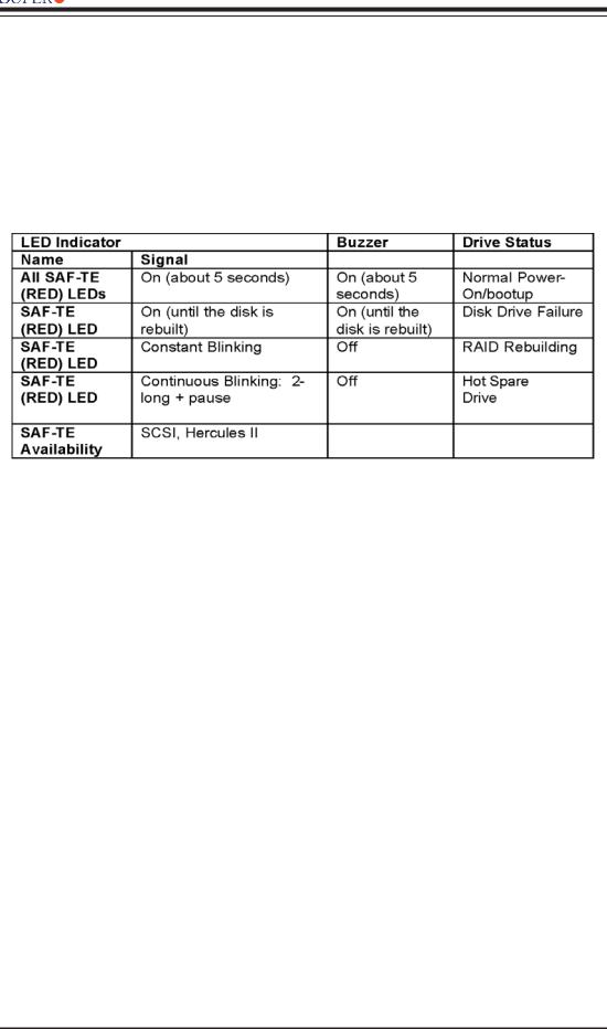
Both AOC-LPZCR1 and AOC-SOZCR1 models offer the feature of SAF-TE. SAF-TE, (-SCSI Accessed Fault-Tolerant Enclosures Interface Specifi cation), is a set of SCSI commands used to monitor hot-swap drives and inform the user of the status of these drives through LED indicators. Refer to the table below for details on SAF-TE LED Indicators.
(*See Note 1 below.)
(*Notes:
*Note 1: SAF-TE in the SATA Mode is available for OEM only. To support SAF-TE,
you will need to have a Supermicro's SATA backplane with the Q-Logic GEM-
424 Enclosure Management Controller pre-installed. By default, this function is
disabled.
*Note 2: SES-2 Enclosure Management in the SAS Mode will be provided when
available.)
2-6

Chapter 2: Technical Specifi cations and Installation
2.4 Safety Guidelines
To avoid personal injury and property damage, please carefully follow all the safety steps listed below when accessing your system
or handling the components:
ESD Safety Guidelines
Electric Static Discharge (ESD) can damage electronic components. To prevent damage to your system. it is important to handle it very carefully. The following measures are generally suffi cient to protect your equipment from ESD.
•Use a grounded wrist strap designed to prevent static discharge.
•Touch a grounded metal object before removing a component from the antistatic bag.
•Handle the RAID card by its edges only; do not touch its components, peripheral chips, memory modules or gold contacts.
•When handling chips or modules, avoid touching their pins.
•Put the card and peripherals back into their antistatic bags when not in use.
General Safety Guidelines
•Always disconnect power cables before installing or removing any components from the computer, including the RAID card.
•Use only the correct type of bracket for the chassis. Please use a full-height bracket for a 1U, 3U, 4U, Tower, or a Pedestal system. Use a low-profi le bracket for a 2U or some of the proprietary chassis. Make sure to secure the bracket in the host system cabinet. (*Note: When used in a 1U system, the full-height bracket is mounted into the riser card.)
•Disconnect the power cable before removing the Extended LED cable, data cable or I2C cable from the riser card.
•Make sure that the riser card is securely seated in the PCI slot to prevent damage to the system due to power shortage.
•Do not force a cable connector onto the controller or a drive.
2-7


 AOC-LPZCR1/AOC-SOZCR1 User's Guide
2.5 Installing the Controller Driver
2.5.1 Creating the Driver Floppy Disk:
A CD-ROM that contains the drivers for the Windows OS, the Linux Red Hat/SuSE OS, and the Controller BIOS is included in the shipping package. Please locate the CD-ROM before installing the driver. (*Note: this CD-ROM does not perform Auto-boot or auto-play.)
For the Windows 32-bit Operating System:
•Copy all fi les from the folder: \Drive\Windows into a blank, formatted fl oppy disk. (The folder is saved in the CDROM that came with your shipment.)
For the Red Hat/SuSE Operating System:
•Make the fl oppy disk by using the diskette image fi le at \Drive\Linux, which is stored in the CD-ROM.
2.5.2 Adding the Driver into an Existing System
(*Note: An existing system is a system that has an operating system already installed and the AOC-LPZCR1/AOC-SOZCR1 driver is being installed as a Secondary Controller.)
For the Windows Operating System
a.Install the controller and make sure that its BIOS appears in POST.
b.Start the Windows OS. The Windows OS will launch the "Found New Hardware Wizard" and search for the installer driver.
c. Insert the driver fl oppy disk that you've created into the computer, select the
fl oppy drive as the source, and press the <Enter> key.
d.Continue clicking <Next> until the driver is successfully installed.
e.Remove the driver disk from the FDD drive and restart the system to complete the installation process.
For the Red Hat/SuSE Operating System
a.Start the Red Hat/SuSE OS.
b.Insert and mount the RPM driver Floppy or CD.
c.Type:"rpm -Uvh fi lename.rpm" at the prompt, and then, follow the instructions given on the screen to install the driver. (*Note: fi lename=the fi le name of the RPM driver that appears on your screen.)
d.Run fdisk, mkfs, and create a mount point for the new driver.
2-8
 Loading...