

8U SuperBlade®
5 MP and 10 DP Blade System
20 DP Blade System
User’s Manual
Revision 1.0

8U SuperBlade User’s Manual
The information in this User’s Manual has been carefully reviewed and is believed to be accurate. The
vendor assumes no responsibility for any inaccuracies that may be contained in this document, makes no
commitment to update or to keep current the information in this manual, or to notify any person or
organization of the updates. Please Note: For the most up-to-date version of this manual, please see
our web site at www.supermicro.com.
Super Micro Computer, Inc. ("Supermicro") reserves the right to make changes to the product described
in this manual at any time and without notice. This product, including software and documentation, is the
property of Supermicro and/or its licensors, and is supplied only under a license. Any use or reproduction
of this product is not allowed, except as expressly permitted by the terms of said license.
IN NO EVENT WILL SUPERMICRO BE LIABLE FOR DIRECT, INDIRECT, SPECIAL, INCIDENTAL,
SPECULATIVE OR CONSEQUENTIAL DAMAGES ARISING FROM THE USE OR INABILITY TO USE
THIS PRODUCT OR DOCUMENTATION, EVEN IF ADVISED OF THE POSSIBILITY OF SUCH
DAMAGES. IN PARTICULAR, SUPERMICRO SHALL NOT HAVE LIABILITY FOR ANY HARDWARE,
SOFTWARE, OR DATA STORED OR USED WITH THE PRODUCT, INCLUDING THE COSTS OF
REPAIRING, REPLACING, INTEGRATING, INSTALLING OR RECOVERING SUCH HARDWARE,
SOFTWARE, OR DATA.
Any disputes arising between manufacturer and customer shall be governed by the laws of Santa Clara
County in the State of California, USA. The State of California, County of Santa Clara shall be the
exclusive venue for the resolution of any such disputes. Super Micro's total liability for all claims will not
exceed the price paid for the hardware product.
FCC Statement: This equipment has been tested and found to comply with the limits for a Class A digital
device pursuant to Part 15 of the FCC Rules. These limits are designed to provide reasonable protection
against harmful interference when the equipment is operated in a commercial environment. This
equipment generates, uses, and can radiate radio frequency energy and, if not installed and used in
accordance with the manufacturer’s instruction manual, may cause harmful interference with radio
communications. Operation of this equipment in a residential area is likely to cause harmful interference,
in which case you will be required to correct the interference at your own expense.
California Best Management Practices Regulations for Perchlorate Materials: This Perchlorate warning
applies only to products containing CR (Manganese Dioxide) Lithium coin cells. Perchlorate
Material-special handling may apply. See www.dtsc.ca.gov/hazardouswaste/perchlorate for further
details.
WARNING: HANDLING OF LEAD SOLDER MATERIALS USED IN THIS PRODUCT MAY
EXPOSE YOU TO LEAD, A CHEMICAL KNOWN TO THE STATE OF CALIFORNIA TO
CAUSE BIRTH DEFECTS AND OTHER REPRODUCTIVE HARM.
Manual Revision 1.0
Release Date: July 10, 2017
Unless you request and receive written permission from Super Micro Computer, Inc., you may not copy
any part of this document.
Information in this document is subject to change without notice. Other products and companies referred
to herein are trademarks or registered trademarks of their respective companies or mark holders.
Copyright © 2017 by Super Micro Computer, Inc.
All rights reserved.
Printed in the United States of America
ii

Preface
About this Manual
This manual is written for professional system integrators, Information Technology
professionals, service personnel and technicians. It provides information for the
installation and use of Supermicro's 8U SuperBlade system. Installation and
maintenance should be performed by experienced professionals only.
Manual Organization
Chapter 1: Introduction
The first chapter provides a checklist of the main components included with the blade
system and describes the main features of the mainboard and enclosure. A quick start
procedure is also provided for your use.
Chapter 2: System Safety
You should familiarize yourself with this chapter for a general overview of safety
precautions that should be followed when installing and servicing the 8U SuperBlade.
Chapter 3: Setup and Installation
Refer here for details on installing the 8U SuperBlade system into a rack.
Chapter 4: System Modules
This chapter covers modules in the 8U SuperBlade system, as well as the CMM module
and configuring double-wide bays.
Chapter 5: Power Supply Modules
This chapter covers the system power supplies and their installation.
Appendix A: System Specifications
This appendix provides a summary of system specifications.
:
i

8U SuperBlade User’s Manual
Notes
ii

Table of Contents
Chapter 1 Introduction.......................................................................1-1
1-1 Overview.............................................................................................1-1
1-2 Quick Start Setup ..............................................................................1-1
1-3 Software Mode Selection ................................................................. 1-2
1-4 Product Checklist of Typical Components..................................... 1-3
1-5 Blade Enclosure Features ...............................................................1-6
Power......................................................................................................1-7
Middle Plane ...........................................................................................1-7
LEDs .......................................................................................................1-7
Enclosure Cooling...................................................................................1-7
1-6 Power Supply Features....................................................................1-8
Power Supply Modules ...........................................................................1-9
Power Cord ........................................................................................1-10
Power Supply Failure.........................................................................1-10
1-7 Special Design Features................................................................1-10
Operating System Support....................................................................1-10
Remote Management ...........................................................................1-10
Computing Density/Power ....................................................................1-10
High-Efficiency Power Supplies ............................................................ 1-11
1-8 Returning Merchandise for Service..............................................1-11
1-9 Contacting Supermicro...................................................................1-12
Chapter 2 Standardized Warning Statements.....................2-1
2-1 About Standardized Warning Statements .....................................2-1
Warning Definition...................................................................................2-1
Installation Instructions ...........................................................................2-3
Circuit Breaker ........................................................................................2-4
Power Disconnection Warning................................................................2-5
Equipment Installation.............................................................................2-6
Restricted Area .......................................................................................2-7
Battery Handling .....................................................................................2-9
Redundant Power Supplies ..................................................................2-10
Backplane Voltage ................................................................................ 2-11
Comply with Local and National Electrical Codes.................................2-12
Product Disposal...................................................................................2-13
Hot Swap Fan Warning.........................................................................2-14
i

8U SuperBlade User’s Manual
Power Cable and AC Adapter ..............................................................2-15
Chapter 3 Setup and Installation.................................................3-1
3-1 Overview.............................................................................................3-1
3-2 Unpacking the System .....................................................................3-1
Choosing a Setup Location.....................................................................3-1
Rack Precautions....................................................................................3-2
Server Precautions .................................................................................3-2
Rack Mounting Considerations ............................................................... 3-2
Ambient Operating Temperature..........................................................3-2
Reduced Airflow ...................................................................................3-2
Mechanical Loading .............................................................................3-2
Circuit Overloading...............................................................................3-3
Reliable Ground ...................................................................................3-3
Installing the System Into a Rack............................................................3-3
Rack Mounting Hardware .......................................................................3-3
Installation...............................................................................................3-4
Chapter 4 System Modules.............................................................4-1
4-1 Chassis Management Module.........................................................4-3
Module Redundancy ............................................................................... 4-5
Determining Master/Slave Modules Status.............................................4-5
CMM Module Installation ........................................................................4-5
Configuring the CMM .............................................................................. 4-6
CMM Functions.......................................................................................4-9
Remote KVM over IP ...........................................................................4-9
Remote Storage (Virtual Media)...........................................................4-9
Serial Over LAN (SOL).........................................................................4-9
Monitoring Functions............................................................................4-9
Power Consumption Management.....................................................4-10
USB Ports and Reset Button ................................................................4-11
USB Ports ..........................................................................................4-11
Reset Button ......................................................................................4-12
Firmware ............................................................................................... 4-12
Web-based Management Utility............................................................4-12
Supported Browsers...........................................................................4-13
Network Connection/Login.................................................................4-13
Address Defaults................................................................................4-13
Home Page ........................................................................................4-14
ii

Chapter 5 Power Supply Modules..............................................5-1
5-1 Power Supply Modules.....................................................................5-1
Power Supply Failure..............................................................................5-4
Installing a Power Supply........................................................................5-4
Removing a Power Supply......................................................................5-4
5-2 Redundant Power Supplies ............................................................. 5-5
5-3 Power Supply Fans...........................................................................5-6
Appendix A System Specifications........................................... A-1
A-1 Enclosure Specifications ................................................................ A-1
A-2 Environmental Specifications......................................................... A-2
A-3 Address Defaults .............................................................................. A-2
A-4 Power Supply Power Calculations ................................................ A-3
iii

8U SuperBlade User’s Manual
Notes
iv

List of Figures
Figure 3-1. Positioning the Enclosure Template ...............................................3-4
Figure 3-2. Securing the Rails to the Rack .......................................................3-4
Figure 3-3. Attaching the Optional Handles ......................................................3-5
Figure 3-4. Enclosure Installed into Rack .........................................................3-6
Figure 4-1. 8U 820C Enclosure with 100G Switch: Rear View .........................4-1
Figure 4-2. 8U 820C Enclosure with 2x25G
and 2x1/10G Switches: Rear View....................................................................4-2
Figure 4-3. Chassis Management Module MBM-CMM-FIO.............................. 4-3
Figure 4-4. Chassis Management Module MBM-CMM-001.............................. 4-4
Figure 4-5. Choose Internal Protocol ................................................................4-7
Figure 4-6. Manually Configure the IP Address ................................................4-7
Figure 4-7. Changing Settings ..........................................................................4-8
Figure 4-8. USB Ports on CMM ......................................................................4-11
Figure 4-9. Home Page................................................................................... 4-14
Figure 5-1. PWS-2K21A-BR Power Supply ......................................................5-2
Figure 5-2. PWS-1K20B-BR Battery Backup Power (BPP) Module .................5-3
Figure 5-3. Power Supply Status ......................................................................5-5
i

8U SuperBlade User’s Manual
Notes
ii

List of Tables
Table 1-1. Networking Module Solutions ..........................................................1-4
Table 1-2. 8U SuperBlade Enclosures.............................................................. 1-6
Table 1-3. Number of Network Modules that May Be Installed
in each Enclosure..............................................................................................1-6
Table 1-4. Enclosure Models and Power Supply Combinations .......................1-8
Table 4-1. Typical 8U Blade System Module Configuration: Rear View...........4-2
Table 4-2. MBM-CMM-FIO Module Interface.................................................... 4-3
Table 4-3. MBM-CMM-FIO Module Features....................................................4-4
Table 4-4. MBM-CMM-001 Module Interface.................................................... 4-4
Table 4-5. MBM-CMM-001 Module Features....................................................4-5
Table 4-6. CMM Reset Settings......................................................................4-12
Table 4-7. Address Defaults............................................................................4-13
Table 5-1. Amperage Draw Specifications
for the PWS-2K21A-BR Power Supply .............................................................5-1
Table 5-2. PWS-2K21A-BR Power Supply Features ........................................5-2
Table 5-3. PWS-1K20B-BR Battery Backup Power (BPP)
Module Specifications .......................................................................................5-3
Table 5-4. PWS-1K20B-BR BPP Module Estimated Runtime ..........................5-4
Table 5-5. Chassis Compatible with the BPP ...................................................5-4
Table A-1. 8U Enclosure Specification Features ............................................. A-1
Table A-2. Environmental Specification Features............................................ A-2
Table A-3. Address Defaults ............................................................................ A-2
Table A-4. Power Supply: Power Calculations (PWS-2K21A-BR)................... A-3
Table A-5. Power Supply: Power Calculations (PWS-1K20B-BR)................... A-3
:
i

8U SuperBlade User’s Manual
Notes
ii

Chapter 1: Introduction
Chapter 1
Introduction
1-1 Overview
The 8U SuperBlade is a compact self-contained server that connects to a pre-cabled
enclosure that provides power, cooling, management and networking functions. One
enclosure can hold up to either ten or twenty blade servers, depending upon the blade
enclosure. This new generation of the 8U SuperBlade enclosure is designed to deliver a
much higher system density, and to incorporate many latest technologies to satisfy the
increasing demands of modern technology and higher computing power.
In this manual, “blade system” refers to the entire system (including the enclosure and
blades servers), “blade” or “blade server” refers to a single blade module and “blade
enclosure” is the unit that the blades, power supplies and modules are housed in.
Each blade server is optimized to fit into either a specific ten-blade or twenty-blade
enclosure.
Please refer to our web site for information on operating systems that have been
certified for use with the 8U SuperBlade (www.supermicro.com/products/superblade/).
1-2 Quick Start Setup
This section covers how to quickly get your new 8U SuperBlade system up and running.
Follow the procedure below to quickly setup your 8U SuperBlade system.
1. Unpack the components of your 8U SuperBlade system and check the packing list
for damaged or missing components.
2. Select a setup location for your system. See "Choosing a Setup Location" on
page 3-1 for details.
3. Mount the 8U SuperBlade chassis in your server rack. See "Installing the System
Into a Rack" on page 3-3 for details.
4. Install the power supply modules into the rear of the 8U SuperBlade chassis. See
"Installing a Power Supply" on page 5-4 for details.
5. Install the CMM module and any switch modules into the rear of the 8U SuperBlade
chassis.
a. For the CMM module, see "CMM Module Installation" on page 4-5 for details.
b. For the InfiniBand and Ethernet modules, see the 8U SuperBlade Network
Modules User’s Manual for details.
c. Attach keyboard, mouse and video connections to your CMM module.
d. Attach network connections for your InfiniBand or Ethernet modules. See the
8U SuperBlade Network Modules User’s Manual for details.
1-1

8U SuperBlade User’s Manual
6. Setup your blade modules for use by doing the following:
a. Open the module case lids of each blade module. Refer to the blade module
user’s manual for details.
b. Install memory into each module. Refer to the blade module user’s manual for
details.
c. Close the module case lids when you have installed your memory for each
blade module. Refer to the blade module user’s manual for details.
d. Install the hard disk drives into each module. Refer to the blade module user’s
manual for details.
e. Install your blade modules into your 8U SuperBlade chassis. Refer to the blade
module user’s manual for details.
7. Connect the power cords for your 8U SuperBlade system’s power supply and plug
them into your power source ONLY after you have installed and secured all system
components.
8. Power up your 8U SuperBlade system. Check to be sure all components are
operating right and are not showing any fault LEDs or alarms in their operation.
9. Install your selected operating system for each blade module. Refer to the blade
module user’s manual for details.
10. Download a BIOS update for each of your blade modules from the Supermicro
website.
1-3 Software Mode Selection
Using the Web-based Management Utility, you can specify your 8U SuperBlade system
to use a quiet mode for quieter operation and lower fan speed. See Section 4-1: Chassis
Management Module on page 4-3 for further details.
1-2

Chapter 1: Introduction
1-4 Product Checklist of Typical Components
• Blade Enclosure (x1): SBE-820C/CB/J/JB, 822/820D, 622 and 422 (8U, 10
full-height 2-socket or 20 half-height blades 4-socket)
• Blade Unit (minimum of 2, 10 or 20 maximum): See the Supermicro website (http://
www.supermicro.com/products/superblade/) for a complete list of blades that can be
mounted in your system. Some examples are listed below:
20 Blade:
• Dual socket (SP) – SBI-4129P-C2N/T3N (205W)
• Single socket Modular Design (SP) – SBI-4119P-C2N/T2N
• Dual socket (HSW/BDW) – SBI-4128R-C2N/T2N
10 Blade:
• 4 Way – SBI-8149R-C4N/T8N
• Power Supplies (up to 8): PWS-2K21A
• CMM Module (x1): MBM-CMM-FIO or MBM-CMM-001
• KVM Cable (x1): CBL-0218L
Optional components include:
• InfiniBand® Switch Module: SBM-IBS-E3616
• Omni-Path™ Switch Module: SBM-OPA-C4020
• Blade IPMI Add-on Card: AOC-SB410-001 (front control board with KVM connector)
• Mezzanine Cards (required for operation with the InfiniBand Switch):
AOC-IBH-X4ED-P (100-Gbps InfiniBand card), AOM-B-4M-100 (M.2 card),
AOM-B3108-H8-B11 (SAS3 card), AOM-SB1-SATA31-P (SATA3 card),
AOC-OPA-WFR (OPA card),
• Ethernet Switches: MBM-XEM-001 (Broadcom 10-Gbps), MBM-XEM-002 (Intel
10-Gbps), MBM-GEM-001 (Intel 1-Gbps), MBM-GEM-004 (Broadcom 1-Gbps)
Additional modules will periodically become available. Please refer to http://
www.supermicro.com/products/superblade for the most current list of modules available
for the 8U SuperBlade.
Blade systems install into standard racks. Up to five 8U blade systems may be installed
into a 19" industry standard 42U rack.
1-3
8U SuperBlade User’s Manual
For some details on the combinations and types of networking modules available, see
Table 1-1 below. See the SuperBlade Network Modules User Manual for full details on
available modules for the SuperBlade system.
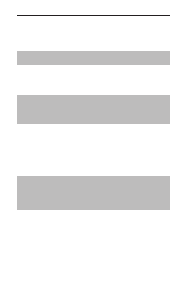
Table 1-1. Networking Module Solutions
8U Enclosure Model
Model Speed Protocol SBE820C(B) SBE820J(B) Notes
20x 100G EDR
InfiniBand downlinks,
SBM-IBH-E3616 100G InfiniBand EDR Up to 1 -
SBM-OPA-C4020 100G Intel Omni-Path Up to 1 -
SBM-25G-100 25G Ethernet - Up to 2
MBM-XEM-001 10G Ethernet Up to 2 Up to 4
16x 100G EDR
InfiniBand uplinks,
7.2Tbps,
PHY: 100G optical/
copper QSFP28.
20x 100G EDR
InfiniBand downlinks,
24x 100G EDR,
InfiniBand uplinks,
1USB Port, 9.6Tbps,
PHY: 100G optical/
copper QSFP28.
20x 25G Ethernet
downlinks, 4x 100G/
40G Ethernet uplinks
(each can split to 4x
25G uplinks w/
optional fan-out
cables, 1x Gigabit
Ethernet uplink, 1
console port
PHY: 100G/40G
optical/copper
QSFP28, Gigabit
Ethernet copper RJ45
56x 10G/2.5G/1G
Ethernet downloads,
4x 40G Ethernet
uplinks, 1 console
port, 1 USB port,
PHY: 960G/40G
optical/copper
QSFP+
1-4
Chapter 1: Introduction
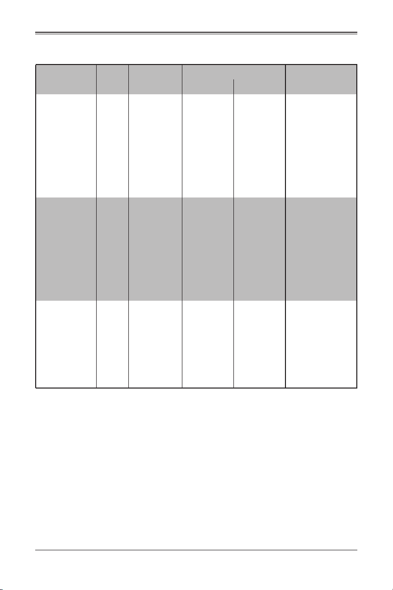
Table 1-1. Networking Module Solutions (Continued)
8U Enclosure Model
Model Speed Protocol SBE820C(B) SBE820J(B) Notes
56x 10G/2.5G/1G
Ethernet downlinks,
2x 40G Ethernet
QSFP+ or, 1x 40G
and 4x 10G Ethernet
MBM-XEM-002 10G Ethernet Up to 2 Up to 4
MBM-GEM-001 1G Ethernet Up to 2 Up to 4
MBM-GEM-004 1G Ethernet Up to 2 Up to 4
uplinks, 1 console
port, 1 USB port
PHY: 1280G/40G
optical/copper
QSFP+, Optional 10G
Ethernet optical/
copper SFP+
56x 2.5G/1G Ethernet
downlinks, 1 Gigabit
Ethernet, 2x 40G
Ethernet or 8x 10G
Ethernet uplinks, 1
console port, 1 USB
port
PHY: 442G/40G
optical/copper
QSFP+, 10G optical/
copper SFP+, Gigabit
Ethernet copper RJ45
40x 1G Ethernet
downlinks, 8x 1G
Ethernet RJ45 and
optional 4x 10G
Ethernet Uplinks, 1
console port
PHY: 176G, Optional
10G optical/copper
SFP+, Gigabit
Ethernet copper RJ45
1-5
8U SuperBlade User’s Manual
1-5 Blade Enclosure Features
Supermicro's blade enclosures are designed to house from 10 to 20 blade units. Each
accommodates up to eight power supplies. The enclosure mid-plane allows the blade
units to share power, cooling and networking. Table 1-2 below describes the various
enclosures, their components and modules. Table 1-3 shows the number of each
module that may be installed in the various enclosure models.
Please check the Supermicro website for the latest module and enclosure installation
information at http://www.supermicro.com/servers/blade/networking/matrix.cfm for
further details.
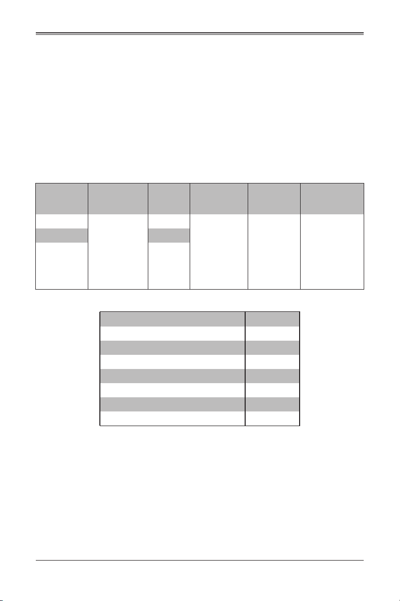
Table 1-2. 8U SuperBlade Enclosures
Enclosure
Model
SBE-820C-822
SBE-820C-622 2200W (x6)
SBE-820C-422 2200W (x4)
Blade Module
Capacity
20-node/
2-socket blades
(half-height)
or
10-node/
4-socket blades
(full-height)
Table 1-3. Number of Network Modules that May Be Installed in each Enclosure
Name (SKU) SBE-820C
Max. CMM Modules supported 1
1G Ethernet Switch(MBM-GEM-001) 2
100G InfiniBand Switch (SBM-IBS-E3616) 1
100G Omni-Path Switch (SBM-OBA-C4020)
Broadcom 10G Switch (MBM-XEM-001) 2
Intel 10G Switch (MBM-XEM-002) 2
Broadcom 1G Switch (MBM-GEM-004) 2
The following sections provide a general outline of the main features for all blade server
enclosures.
Power
Supply
Options
2200W (x8)
Intel Blade
Options
SBI-4129P-T3N/
C2N
AMD Blade
Options
NA
Module
Options
SBM-IBS-E3616
SBM-OPA-C4020
MBM-XEM-001
MBM-XEM-002
MBM-GEM-001
MBM-GEM-004
MBM-CMM-FIO
MBM-CMM-001
1-6

Chapter 1: Introduction
Power
The typical blade enclosure features a 2200W power system composed of four, six, or
eight power supply modules. An alternate configuration (and required for a full 10 or
20-blade system) features a total of four power supply modules for redundancy. This
power redundancy feature allows you to replace the failing power module while the
backup module takes over to keep the system running. You must have either two, four
or eight power supply modules installed in the blade enclosure (eight is recommended in
a full system).
The Chassis Management Module assumes the worst case (maximum) power for any
model of blade prior to applying power. If the power supplies cannot supply that amount
of the required power for the given load on the power supplies, then the CMM will not
allow that unit to power up. After a blade is powered up, the blade’s BIOS calculates the
actual power load required by the blade based upon the installed devices and informs
the CMM of its requirements. The CMM then adjusts the remaining supply of power for
additional blades based upon the actual delta of the total power, minus the amount of
power being used by the blades that are powered on.
Middle Plane
The middle plane connects the various capabilities of the blades, such as the various
speed switch(es) to Network Interface Controller(s), the Chassis Management Module
(CMM) to the USB devices and the InfiniBand Switch to the Host Channel Adapters.
These devices all connect to the middle plane through high density connectors that
provide both signals and power. This type of configuration reduces the amount of
system cabling and simplifies the task of setting up the system. It provides an alternative
signals route to support redundant power, CMM, network and IPMI functions.
NOTE: Signaling information can NOT be physically routed from one blade to another.
LEDs
Two LEDs are located at the right top of the enclosure above the last or right most
blade. The left LED provides Power Status information and the right LED is the Fault
LED.
Enclosure Cooling
The cooling for the entire blade system is provided by the fans in the power supply
modules or optional fans that can be installed in place of a power supply. If a power
supply fails, its fans will continue to operate to provide continuous cooling. For this
reason, a failed power supply should remain installed in the enclosure until a
replacement unit is ready.
NOTE: Fans are controlled by Auto Mode or User Mode (User Mode from level 1 to 10).
WARNING: The fans are very noisy at full speed and it is recommended that they not be run
at full speed when in use in an office or near populated workstations.
1-7

8U SuperBlade User’s Manual
For the SBE-820C enclosures, three additional cooling fan modules, each with two
cooling fans, are in the rear of the enclosure. Also, additional fan modules are available
for substitution of power supply slots in the enclosure.
NOTE: In order to prevent air flow leaks that would reduce cooling efficiency in the blade
system’s enclosure, install dummy blades to close off any blade slots that do not have active
blade modules installed in them.
For overheat problems, check that there are no obstructions (such as poorly routed
cables), check that all fans are operating normally and make sure the ambient room
temperature is not too warm (refer to Section A-2: Environmental Specifications on
page A-2 for the maximum operating temperature). You can also use either of the blade
management software utilities to increase the fan speed and maximize system cooling.
In the event of a power overload, you will have to add additional power supply modules
to take up the load. Otherwise, you will not be able to power up all the blade modules.
The blade BIOS plus CMM firmware calculates the load to determine if the power
supplies can adequately handle the total system configuration.
1-6 Power Supply Features
The 8U SuperBlade enclosure comes standard with one CMM module and up to eight
power supplies. Information on the power supplies is summarized below. See
Section 4-1: Chassis Management Module on page 4-3 for details on the CMM module
and Chapter 5 for details on the power supplies.
If you install only four power supplies in the enclosure, they should be installed in the
lower rather than the upper power bays. The reason for this counter-intuitive installation
is that the power supplies in the lower bays provide increased airflow across the
memory modules within each blade module. See the table below for details on the
power supplies for the different models of enclosures.
Table 1-4. Enclosure Models and Power Supply Combinations
Enclosure Model Power Supplies and Fan Combinations
820C/J-822 8x hot-swappable 2200W Titanium Level (96% efficiency)
820C/J-622 6x hot-swappable 2200W Titanium Level (96% efficiency) + 2 fans
820C/J-422 4x hot-swappable 2200W Titanium Level (96% efficiency) + 4 fans
820C/J-820D 8x hot-swappable 2000W DC PWS
820CB-422 4x hot-swappable 2200W + 4x 1200W BBP modules
820JB-422 4x hot-swappable 2200W + 4x 1200W BBP modules
1-8

Chapter 1: Introduction
Power Supply Modules
Each power supply module has its own power cord. Eight modules are required when
the full complement of blade units are installed into an enclosure. An LED on the back of
a power supply will be red when AC power is present and green when the power is on.
Supermicro's high-efficiency blade system power supplies deliver continuous redundant
power up to 96% peak efficiency. Each power supply module includes a management
module that monitors the power supplies and the power enclosure.
See Chapter 5 for specifications and details on the power supplies available for the
SuperBlade system.
1-9

8U SuperBlade User’s Manual
Power Cord
Each power supply module has a C-20 type socket (IEC-60320-C20) for AC power and
the power cord must have a C-19 type connector (IEC-60320-C19) to connect to the
power supply.
A plastic locking clip partially covering the socket was designed to prevent the power
supply module from being removed with the power cord still connected.
Refer to Appendix A for power/amperage calculation tables.Refer to the supermicro web
site for further details on power cords.
Power Supply Failure
If a power supply or a fan in a power supply fails, the system management software will
notify you of the situation. In either case, you will need to replace the power supply
module with another identical one. Please note that if a power supply fails, its fans will
continue to operate to provide system cooling. For this reason, a failed power supply
should remain installed in the enclosure until a replacement unit is ready.
See Chapter 5 for the procedure on replacing power supplies.
1-7 Special Design Features
Supermicro's 8U SuperBlade offers special design features, some of which no other
blade server can duplicate. These features give you extraordinary flexibility in
configuring a blade system for your own particular needs.
Operating System Support
Please check with the SMC web page for certified OS at: https://www.supermicro.com/
support/resources/OS/OS_Certification_Intel.cfm.
Remote Management
The Chassis Management Module (CMM) can manage the whole enclosure and any
individual blade module by switching around to it.
NOTE: Some Blade modules already have onboard BMC.
An additional feature for the SBE-822 enclosures is an extra IPMI and Com port in card
(part # FPB-FP820B-IPMI) that attaches to the left carry handle of the enclosure. This
allows you a connection in the front of the enclosure for connection to the system.
Computing Density/Power
Dual and quad core processors are supported in the blade module systems. Each 8U
SuperBlade mainboard supports two or four processors and up to 2 TB of main memory.
This translates to a maximum potential of up to 40 processors and 61 TB of memory per
8U enclosure or 200 processors and 307 TB of memory for a 42U rack.
1-10

Chapter 1: Introduction
High-Efficiency Power Supplies
A reliable source of power is critical in server systems and even more so in a blade
system, where up to fourteen systems (blades) share the same power source. 8U
SuperBlade power supplies have been designed to operate at up to 96% peak efficiency
and provide redundancy. Using high-efficiency power supplies results in a measurable
reduction in wasted energy consumption and generated heat.
1-8 Returning Merchandise for Service
A receipt or copy of your invoice marked with the date of purchase is required before
any warranty service will be rendered. You can obtain service by calling your vendor for
a Returned Merchandise Authorization (RMA) number. When returning to the
manufacturer, the RMA number should be prominently displayed on the outside of the
shipping carton, and mailed prepaid or hand-carried. Shipping and handling charges will
be applied for all orders that must be mailed when service is complete.
This warranty only covers normal consumer use and does not cover damages incurred
in shipping or from failure due to the alteration, misuse, abuse or improper maintenance
of products.
During the warranty period, contact your distributor first for any product problems.
For faster service, RMA authorizations may be requested online at:
http://www. supermicro.com/support/rma/
1-11

8U SuperBlade User’s Manual
1-9 Contacting Supermicro
Headquarters
Address: Super Micro Computer, Inc.
980 Rock Ave.
San Jose, CA 95131 U.S.A.
Tel: +1 (408) 503-8000
Fax: +1 (408) 503-8008
Email:
Website: www.supermicro.com
Europe
Address: Super Micro Computer B.V.
Tel: +31 (0) 73-6400390
Fax: +31 (0) 73-6416525
Email:
Asia-Pacific
Address: Super Micro Computer, Inc.
Tel: +886-(2) 8226-3990
Fax: +886-(2) 8226-3992
Website: www.supermicro.com.tw
Technical Support:
Email: support@supermicro.com.tw
marketing@supermicro.com (General Information)
support@supermicro.com (Technical Support)
Het Sterrenbeeld 28, 5215 ML
‘s-Hertogenbosch, The Netherlands
sales@supermicro.nl (General Information)
support@supermicro.nl (Technical Support)
rma@supermicro.nl (Customer Support)
3F, No. 150, Jian 1st Rd.
Zhonghe Dist., New Taipei City 23511
Taiwan (R.O.C)
1-12

Chapter 2: Standardized Warning Statements
Chapter 2
Standardized Warning Statements
2-1 About Standardized Warning Statements
The following statements are industry standard warnings, provided to warn the user of
situations which have the potential for bodily injury. Should you have questions or
experience difficulty, contact Supermicro's Technical Support department for assistance.
Only certified technicians should attempt to install or configure components.
Read this appendix in its entirety before installing or configuring components in the
Supermicro chassis
These warnings may also be found on our web site at http://
www.supermicro.com/about/policies/safety_information.cfm.
Warning Definition
Warning!
This warning symbol means danger. You are in a situation that could cause
bodily injury. Before you work on any equipment, be aware of the hazards
involved with electrical circuitry and be familiar with standard practices for preventing
accidents.
警告の定義
この警告サインは危険を意味します。
人身事故につながる可能性がありますので、いずれの機器でも動作させる前に、
電気回路に含まれる危険性に注意して、標準的な事故防止策に精通して下さい。
㬌嬎⏲䫎⎟ẋ堐⌙昑ˤ
ぐ㬋⢬Ḷ⎗傥⍿⇘慵Ọ⭛䘬ⶍἄ䍗⠫ˤ⛐ぐἧ䓐学⢯⺨⥳ⶍἄ⇵炻⽭栣↮シ孮⇘
妎䓝䘬⌙昑炻⸞䅇乫㌴㎉旚㬊ḳ㓭⍹䓇䘬㞯Ⅾⶍἄ䦳⸷ˤ実㟡㌖㭷校嬎⏲乻⯦䘬⢘㖶⎟䞩
㈦⇘㬌学⢯䘬⬱ℐ⿏嬎⏲宜㖶䘬侣孹㔯㛔ˤ
㬌嬎⏲䫎嘇ẋ堐⌙晒ˤ
ぐ㬋嗽㕤⎗傥幓橼⎗傥㚫⍿㎵ 䘬ⶍἄ䑘⠫ˤ⛐ぐἧ䓐ảỽ姕⁁⇵炻婳㲐シ妠暣䘬⌙
晒炻ᶼ天䅇〱枸旚ḳ㓭䘤䓇䘬㧁㸾ⶍἄ䦳⸷ˤ婳ὅ䄏㭷ᶨ㲐シḳ枭⼴䘬嘇䡤㈦⇘䚠斄䘬
侣嬗婒㖶ℏ⭡ˤ
2-1

8U SuperBlade User’s Manual
ןונקת תורהצהאהרהז
Warnung
WICHTIGE SICHERHEITSHINWEISE
Dieses Warnsymbol bedeutet Gefahr. Sie befinden sich in einer Situation, die zu
Verletzungen führen kann. Machen Sie sich vor der Arbeit mit Geräten mit den Gefahren
elektrischer Schaltungen und den üblichen Verfahren zur Vorbeugung vor Unfällen
vertraut. Suchen Sie mit der am Ende jeder Warnung angegebenen
Anweisungsnummer nach der jeweiligen Übersetzung in den übersetzten
Sicherheitshinweisen, die zusammen mit diesem Gerät ausgeliefert wurden.
BEWAHREN SIE DIESE HINWEISE GUT AUF.
INSTRUCCIONES IMPORTANTES DE SEGURIDAD
Este símbolo de aviso indica peligro. Existe riesgo para su integridad física. Antes de
manipular cualquier equipo, considere los riesgos de la corriente eléctrica y
familiarícese con los procedimientos estándar de prevención de accidentes. Al final de
cada advertencia encontrará el número que le ayudará a encontrar el texto traducido en
el apartado de traducciones que acompaña a este dispositivo.
GUARDE ESTAS INSTRUCCIONES.
IMPORTANTES INFORMATIONS DE SÉCURITÉ
Ce symbole d'avertissement indique un danger. Vous vous trouvez dans une situation
pouvant entraîner des blessures ou des dommages corporels. Avant de travailler sur un
équipement, soyez conscient des dangers liés aux circuits électriques et
familiarisez-vous avec les procédures couramment utilisées pour éviter les accidents.
Pour prendre connaissance des traductions des avertissements figurant dans les
consignes de sécurité traduites qui accompagnent cet appareil, référez-vous au numéro
de l'instruction situé à la fin de chaque avertissement.
CONSERVEZ CES INFORMATIONS.
ה וא תולאש שיו הדימב .תירשפא תיזיפי ,יהשלכ היעבב תולקתרוציל שי הכימת תקלחמ םע רשק
ןה תואבה תורהצהא ינפמ שמתשמה תא ריהזהל תנמ לע ,היישעתה ינקת יפ לע תורהז הלבח
רידגהל וא ןיקתהל םיאשר דבלב םיכמסומ םיאנכט .ורקימרפוס לש תינכט תאה .םיביכר
. ﻲﻓ ﻚﻧا نأ ﻦﻜﻤﯾ ﺔﻟﺎﺣ ﻲﻓ ﺐﺒﺴﺘﺗ ﺔﺑﺎﺻا ﺔﯾﺪﺴﺟ ﺰﻣﺮﻟا اﺬھ ﻲﻨﻌﯾ ﺮﻄﺧ !ﺮﯾﺬﺤﺗ
نأ ﻞﺒﻗ يأ ﻰﻠﻋ ﻞﻤﻌﺗ تاﺪﻌﻣ،ﻛﻢﻠﻋ ﻰﻠﻋ ﻦ ﻦﻋ ﺔﻤﺟﺎﻨﻟا ﺮطﺎﺨﻤﻟﺎﺑ ﺮﺋاوﺪﻟا
ﻢﻗر مﺪﺨﺘﺳا نﺎﯿﺒﻟا صﻮﺼﻨﻤﻟا ﺔﯾﺎﮭﻧ ﻲﻓ ﺮﯾﺬﺤﺗ ﻞﻛ رﻮﺜﻌﻠﻟ ﺎﮭﺘﻤﺟﺮﺗ
안전을 위한 주의사항
경고 !
2-2
ן
אורקל שי .ורקימרפוס יזראמב םיביכרה תרדגה וא תנקתה ינפל ואולמב חפסנה תא
ﺔﯿﺋﺎﺑﺮﮭﻜﻟا
ﻛوﺔﯾارد ﻰﻠﻋ ﻦ رﺎﻤﻤﻟﺎﺑتﺎﺳ ﺔﯿﺋﺎﻗﻮﻟا ﻟ ﻊﻨﻤعﻮﻗو يأثداﻮﺣ

Chapter 2: Standardized Warning Statements
이 경고 기호는 위험이 있음을 알려 줍니다 . 작업자의 신체에 부상을 야기 할 수 있는
상태에 있게 됩니다 . 모든 장비에 대한 작업을 수행하기 전에 전기회로와 관련된 위험
요소들을 확인하시고 사전에 사고를 방지할 수 있도록 표준 작업절차를 준수해 주시기
바랍니다 .
해당 번역문을 찾기 위해 각 경고의 마지막 부분에 제공된 경고문 번호를 참조하십시오
BELANGRIJKE VEILIGHEIDSINSTRUCTIES
Dit waarschuwings symbool betekent gevaar. U verkeert in een situatie die lichamelijk
letsel kan veroorzaken. Voordat u aan enige apparatuur gaat werken, dient u zich
bewust te zijn van de bij een elektrische installatie betrokken risico's en dient u op de
hoogte te zijn van de standaard procedures om ongelukken te voorkomen. Gebruik de
nummers aan het eind van elke waarschuwing om deze te herleiden naar de
desbetreffende locatie.
BEWAAR DEZE INSTRUCTIES
Installation Instructions
Warning!
Read the installation instructions before connecting the system to the power
source.
設置手順書
システムを電源に接続する前に、設置手順書をお読み下さい。
嬎⏲
⮮㬌䲣亇徆㍍䓝㸸⇵ - 実断宣⬱塭宜㖶ˤ
嬎⏲
⮯䲣䴙冯暣㸸忋㍍⇵炻婳教嬨⬱墅婒㖶ˤ
Warnung
Vor dem Anschließen des Systems an die Stromquelle die Installationsanweisungen
lesen.
¡Advertencia!
Lea las instrucciones de instalación antes de conectar el sistema a la red de
alimentación.
Attention
Avant de brancher le système sur la source d'alimentation, consulter les directives
d'installation.
אורקל שי רוקמל תכרעמה רוביח ינפל הנקתה תוארוה תאחתמ.
2-3

8U SuperBlade User’s Manual
ﻟا تادﺎﺷرإ ﺮﻗاﺐﯿﻛﺮﺘ ﻞﯿﺻﻮﺗ ﻞﺒﻗ ﻰﻟإ مﺎﻈﻨﻟا ﺔﻗﺎﻄﻠﻟ رﺪﺼﻣ
시스템을 전원에 연결하기 전에 설치 안내를 읽어주십시오 .
Waarschuwing
Raadpleeg de installatie-instructies voordat u het systeem op de voedingsbron aansluit.
Circuit Breaker
Warning!
This product relies on the building's installation for short-circuit (overcurrent)
protection. Ensure that the protective device is rated not greater than: 250 V,
20 A.
サーキット・ブレーカー
この製品は、短絡(過電流)保護装置がある建物での設置を前提としています。
保護装置の定格が 250V、20A を超えないことを確認下さい。
嬎⏲
㬌ṏ⑩䘬䞕嶗 ) 彯弥䓝㳩 * ᾅ㉌䓙⺢䫹䈑䘬ὃ䓝䲣亇㍸ὃ - 䠖ᾅ䞕嶗ᾅ㉌学⢯䘬桅⭂䓝㳩
ᶵ⣏Ḷ 361W-31Bˤ
嬎⏲
㬌䓊⑩䘬䞕嶗 ) 忶庱暣㳩 * ᾅ嬟䓙⺢䭱䈑䘬ὃ暣䲣䴙㍸ὃ - 䡢ᾅ䞕嶗ᾅ嬟姕⁁䘬柵⭂暣
㳩ᶵ⣏㕤 361W-31Bˤ
Warnung
Dieses Produkt ist darauf angewiesen, dass im Gebäude ein Kurzschluss- bzw.
Überstromschutz installiert ist. Stellen Sie sicher, dass der Nennwert der
Schutzvorrichtung nicht mehr als: 250 V, 20 A beträgt.
¡Advertencia!
Este equipo utiliza el sistema de protección contra cortocircuitos (o sobrecorrientes) del
edificio. Asegúrese de que el dispositivo de protección no sea superior a: 250 V, 20 A.
Attention
Pour ce qui est de la protection contre les courts-circuits (surtension), ce produit dépend
de l'installation électrique du local. Vérifiez que le courant nominal du dispositif de
protection n'est pas supérieur à :250 V, 20 A.
2-4
לע ךמתסמ הז רצומנגהה תעינמל םינבמב תנקתומה יכ אדוול שי .ילמשח רצק
רצקה ינפמ ןגמה רישכמה ילמשחהמ רתוי אל אוה-250 V, 20 A

Chapter 2: Standardized Warning Statements
ﺞﺘﻨﻤﻟا اﺬھ ﻰﻠﻋ ﺪﻤﺘﻌﯾ تاﺪﻌﻣ ﺔﯾﺎﻤﺤﻟا ةﺮﯿﺼﻘﻟاﺮﺋاوﺪﻟا ﻦﻣ ﺎﮭﺘﯿﺒﺜﺗ ﻢﺗ ﻲﺘﻟا ﻲﻓ
ﻰﻨﺒﻤﻟا
20A, 250V : ﻦﻣ ﺪﻛﺄﺗ نأ ﻢﯿﯿﻘﺗ زﺎﮭﺠﻟا ﻟاﻲﺋﺎﻗﻮ ﺲﯿﻟ ﻦﻣ ﺮﺜﻛأ
경고 !
이 제품은 전원의 단락 ( 과전류 ) 방지에 대해서 전적으로 건물의 관련 설비에 의존합니
다 . 보호장치의 정격이 반드시 250V( 볼트 ), 20A( 암페어 ) 를 초과하지 않도록 해야
합니다 .
Waarschuwing
Dit product is afhankelijk van de kortsluitbeveiliging (overspanning) van uw electrische
installatie. Controleer of het beveiligde aparaat niet groter gedimensioneerd is dan
220V, 20A.
Power Disconnection Warning
Warning!
The system must be disconnected from all sources of power and the power
cord removed from the power supply module(s) before accessing the chassis
interior to install or remove system components.
電源切断の警告
システムコンポーネントの取り付けまたは取り外しのために、シャーシー内部にアクセ
スするには、
システムの電源はすべてのソースから切断され、電源コードは電源モジュールから取り
外す必要があります。
嬎⏲
⛐Ἀㇻ⺨㛢䭙⸞⬱塭ㆾ䦣昌ℭ悐☐ẞ⇵ - ⽭栣⮮䲣亇⬴ℐ㕕䓝 - ⸞䦣昌䓝㸸乧ˤ
嬎⏲
⛐ぐㇻ攳㨇㭤⬱墅ㆾ䦣昌ℏ悐ẞ⇵炻⽭枰⮯䲣䴙⬴ℐ㕟暣炻䦣昌暣㸸䶂ˤ
Warnung
Das System muss von allen Quellen der Energie und vom Netzanschlusskabel getrennt
sein, das von den Spg.Versorgungsteilmodulen entfernt wird, bevor es auf den
Chassisinnenraum zurückgreift, um Systemsbestandteile anzubringen oder zu
entfernen.
2-5

8U SuperBlade User’s Manual
ילמשח קותינ ינפמ הרהזא
!הרהזא
¡Advertencia!
El sistema debe ser disconnected de todas las fuentes de energía y del cable eléctrico
quitado de los módulos de fuente de alimentación antes de tener acceso el interior del
chasis para instalar o para quitar componentes de sistema.
Attention
Le système doit être débranché de toutes les sources de puissance ainsi que de son
cordon d'alimentation secteur avant d'accéder à l'intérieur du chassis pour installer ou
enlever des composants de systéme.
י
למשחה תורוקמ לכמ תכרעמה תא קתנל שי ריסהל שיו קפסהמ ילמשחה לבכ תא
נקתה ךרוצל זראמה לש ימינפה קלחל השיג ינפלת רסה ואת .םיביכר
ﻞﺼﻓ ﺐﺠﯾ مﺎﻈﻨﻟا ﻊﯿﻤﺟ ﻦﻣردﺎﺼﻣ ﺔﻗﺎﻄﻟا ﺔﻟازإو ءﺎﺑﺮﮭﻜﻟا ﻚﻠﺳ ﻦﻣ ةﺪﺣو داﺪﻣا
ﻰﻟإ لﻮﺻﻮﻟا ﺔﯿﻠﺧاﺪﻟا ﻖطﺎﻨﻤﻟا ﻟﻞﻜﯿﮭﻠ ﺔﻟازإ وأ ﺖﯿﺒﺜﺘﻟ تﺎﻧﻮﻜﻣ زﺎﮭﺠﻟا
경고 !
시스템에 부품들을 장착하거나 제거하기 위해서는 섀시 내부에 접근하기 전에 반드시
전원 공급장치로부터 연결되어있는 모든 전원과 전기코드를 분리해주어야 합니다 .
ﺔﻗﺎﻄﻟا ﻞﺒﻗ
Waarschuwing
Voordat u toegang neemt tot het binnenwerk van de behuizing voor het installeren of
verwijderen van systeem onderdelen, dient u alle spanningsbronnen en alle
stroomkabels aangesloten op de voeding(en) van de behuizing te verwijderen.
Equipment Installation
Warning!
Only trained and qualified personnel should be allowed to install, replace, or
service this equipment.
機器の設置
トレーニングを受け認定された人だけがこの装置の設置、交換、またはサービスを許
可されています。
嬎⏲
⎒㚱乷彯➡孕ᶼ℟㚱峬㟤䘬Ṣ␀ㇵ傥徃埴㬌学⢯䘬⬱塭ˣ㚜㌊亜ᾖˤ
嬎⏲
⎒㚱䴻忶⍿妻ᶼ℟屯㟤Ṣ⒉ㇵ⎗⬱墅ˣ㚜㎃冯䵕ᾖ㬌姕⁁ˤ
2-6

Chapter 2: Standardized Warning Statements
Warnung
Das Installieren, Ersetzen oder Bedienen dieser Ausrüstung sollte nur geschultem,
qualifiziertem Personal gestattet werden.
¡Advertencia!
Solamente el personal calificado debe instalar, reemplazar o utilizar este equipo.
Attention
Il est vivement recommandé de confier l'installation, le remplacement et la maintenance
de ces équipements à des personnels qualifiés et expérimentés.
!הרהזא
שר דבלב ךמסומ תווצתא ףילחהל ,ןיקתהל יא .דויצה רובע תוריש תתל וא דויצה
ﻦﯿﺑرﺪﻤﻟاو و ﺐﯿﻛﺮﺘﻟلاﺪﺒﺘﺳا وأ ﺔﻣﺪﺧ زﺎﮭﺠﻟا اﺬھ ﺢﻤﺴﯾ نأ ﺐﺠﯾ ﻂﻘﻓ ﻦﯿﻠھﺆﻤﻟا ﻦﯿﻔظﻮﻤﻠﻟ
경고 !
훈련을 받고 공인된 기술자만이 이 장비의 설치 , 교체 또는 서비스를 수행할 수 있습니
다.
Waarschuwing
Deze apparatuur mag alleen worden geïnstalleerd, vervangen of hersteld door
geschoold en gekwalificeerd personeel.
Restricted Area
Warning!
This unit is intended for installation in restricted access areas. A restricted
access area can be accessed only through the use of a special tool, lock and
key, or other means of security. (This warning does not apply to workstations).
アクセス制限区域
このユニットは、アクセス制限区域に設置されることを想定しています。
アクセス制限区域は、特別なツール、鍵と錠前、その他のセキュリティの手段を用い
てのみ出入りが可能です。
嬎⏲
㬌悐ẞ⸼⬱塭⛐旸⇞徃↢䘬⛢炻旸⇞徃↢䘬⛢㊯⎒傥忂彯ἧ䓐䈡㬲ⶍ℟ˣ撩摍⋁ㆾ
℞⬫⬱ℐㇳ㭝徃↢䘬⛢ˤ
嬎⏲
㬌墅伖旸⬱墅㕤忚↢䭉⇞⋨➇炻忚↢䭉⇞⋨➇Ὢ㊯傥ẍ䈡㬲ⶍ℟ˣ挾柕⍲搘⋁ㆾ℞
Ṿ⬱ℐ㕡⺷ㇵ傥忚ℍ䘬⋨➇ˤ
2-7

8U SuperBlade User’s Manual
תלבגומ השיג םע רוזא
!הרהזא
Warnung
Diese Einheit ist zur Installation in Bereichen mit beschränktem Zutritt vorgesehen. Der
Zutritt zu derartigen Bereichen ist nur mit einem Spezialwerkzeug, Schloss und
Schlüssel oder einer sonstigen Sicherheitsvorkehrung möglich.
¡Advertencia!
Esta unidad ha sido diseñada para instalación en áreas de acceso restringido. Sólo
puede obtenerse acceso a una de estas áreas mediante la utilización de una
herramienta especial, cerradura con llave u otro medio de seguridad.
Attention
Cet appareil doit être installée dans des zones d'accès réservés. L'accès à une zone
d'accès réservé n'est possible qu'en utilisant un outil spécial, un mécanisme de
verrouillage et une clé, ou tout autre moyen de sécurité.
ת
תרזעב תנתינ השיגה .השיג תלבגה םהב שיש םירוזאב הדיחיה תא ןיקתהל שי
.('דכו לוענמ ,חתפמ) דבלב החטבא ילכ
. ﺺﯿﺼﺨﺗ ةﺪﺣﻮﻟا هﺬھ ﻲﻓ ﺎﮭﺒﯿﻛﺮﺘﻟ ﻖطﺎﻨﻣ ةرﻮﻈﺤﻣ ﻢﺗ
ﺻﻮﻟا ﻦﻜﻤﯾﻰﻟإ لﻮ ﺔﻘﻄﻨﻣ ةرﻮﻈﺤﻣ ﻂﻘﻓ ماﺪﺨﺘﺳا لﻼﺧ ﻦﻣ ،ﺔﺻﺎﺧ ةادأ
وأ يأ ﻼﻟ ىﺮﺧأ ﺔﻠﯿﺳونﺎﻣﻷ حﺎﺘﻔﻣو ﻞﻔﻗ
경고 !
이 장치는 접근이 제한된 구역에 설치하도록 되어있습니다 . 특수도구 , 잠금 장치 및 키
, 또는 기타 보안 수단을 통해서만 접근 제한 구역에 들어갈 수 있습니다 .
Waarschuwing
Dit apparaat is bedoeld voor installatie in gebieden met een beperkte toegang. Toegang
tot dergelijke gebieden kunnen alleen verkregen worden door gebruik te maken van
speciaal gereedschap, slot en sleutel of andere veiligheidsmaatregelen.
2-8

Chapter 2: Standardized Warning Statements
!הרהזא
Battery Handling
Warning!
There is the danger of explosion if the battery is replaced incorrectly. Replace
the battery only with the same or equivalent type recommended by the
manufacturer. Dispose of used batteries according to the manufacturer's instructions.
電池の取り扱い
電池交換が正しく行われなかった場合、破裂の危険性があります。交換する電池は
メーカーが推奨する型、または同等のものを使用下さい。使用済電池は製造元の指示
に従って処分して下さい。
嬎⏲
䓝㰈㚜㌊ᶵỂ㚱䆮䁠⌙昑ˤ実⎒ἧ䓐⎴䰣䓝㰈ㆾ⇞忈⓮㍐勸䘬≇傥䚠䘬䓝㰈㚜㌊⍇㚱
䓝㰈ˤ実㊱⇞忈⓮䘬宜㖶⢬䎮⹇㖏䓝㰈ˤ
嬎⏲
暣㰈㚜㎃ᶵ䔞㚫㚱䆮䁠⌙晒ˤ婳ἧ䓐墥忈⓮⺢嬘䚠⎴ㆾ≇傥䚠䔞䘬暣㰈㚜㎃⍇㚱暣
㰈ˤ婳㊱䄏墥忈⓮䘬婒㖶㊯䣢嗽䎮⺊㡬冲暣㰈ˤ
Warnung
Bei Einsetzen einer falschen Batterie besteht Explosionsgefahr. Ersetzen Sie die
Batterie nur durch den gleichen oder vom Hersteller empfohlenen Batterietyp.
Entsorgen Sie die benutzten Batterien nach den Anweisungen des Herstellers.
Attention
Danger d'explosion si la pile n'est pas remplacée correctement. Ne la remplacer que par
une pile de type semblable ou équivalent, recommandée par le fabricant. Jeter les piles
usagées conformément aux instructions du fabricant.
¡Advertencia!
Existe peligro de explosión si la batería se reemplaza de manera incorrecta.
Reemplazar la batería exclusivamente con el mismo tipo o el equivalente recomendado
por el fabricante. Desechar las baterías gastadas según las instrucciones del fabricante.
경고 !
2-9
תנכס תמייקץוציפ .הניקת אל ךרדב הפלחוהו הדימב הללוסה לש ףילחהל שי
גוסב הללוסה תא מ םאותה תרבחלמומ ןרציתצ.
תוללוסה קוליס תושמושמה עצבל שי .ןרציה תוארוה יפל
ﺮﻄﺧ كﺎﻨھ ﻦﻣ لاﺪﺒﺘﺳا ﺔﻟﺎﺣ ﻲﻓ رﺎﺠﻔﻧا ﺔﯾرﺎﻄﺒﻟا ﺔﺤﯿﺤﺻ ﺮﯿﻏ ﺔﻘﯾﺮﻄﺑ ﻚﯿﻠﻌﻓ
ﺔﯾرﺎﻄﺒﻟا لاﺪﺒﺘﺳا
ﻂﻘﻓ عﻮﻨﻟا ﺲﻔﻨﺑ ﺎﮭﻟدﺎﻌﯾ ﺎﻣ وأ ﺎﻤﻛﺖﺻوأ ﺔﻌﻨﺼﻤﻟا ﺔﻛﺮﺸﻟا ﮫﺑ
تﺎﯾرﺎﻄﺒﻟا ﻦﻣ ﺺﻠﺨﺗ ﻟ ﺎﻘﻓو ﺔﻠﻤﻌﺘﺴﻤﻟاﺔﻌﻧﺎﺼﻟا ﺔﻛﺮﺸﻟا تﺎﻤﯿﻠﻌﺘ

8U SuperBlade User’s Manual
דחא קפסמ רתוי םייק םא
!הרהזא
배터리가 올바르게 교체되지 않으면 폭발의 위험이 있습니다 . 기존 배터리와 동일하거
나 제조사에서 권장하는 동등한 종류의 배터리로만 교체해야 합니다 . 제조사의 안내에
따라 사용된 배터리를 처리하여 주십시오 .
Waarschuwing
Er is ontploffingsgevaar indien de batterij verkeerd vervangen wordt. Vervang de batterij
slechts met hetzelfde of een equivalent type die door de fabrikant aanbevolen wordt.
Gebruikte batterijen dienen overeenkomstig fabrieksvoorschriften afgevoerd te worden.
Redundant Power Supplies
Warning!
This unit might have more than one power supply connection. All connections
must be removed to de-energize the unit.
冗長電源装置
このユニットは複数の電源装置が接続されている場合があります。
ユニットの電源を切るためには、すべての接続を取り外さなければなりません。
嬎⏲
㬌悐ẞ徆㍍䘬䓝㸸⎗傥ᶵ㬊ᶨ炻⽭栣⮮㚱䓝㸸㕕⺨ㇵ傥 㬊亁宍悐ẞὃ䓝ˤ
嬎⏲
㬌墅伖忋㍍䘬暣㸸⎗傥ᶵ⎒ᶨᾳ炻⽭枰↯㕟㚱暣㸸ㇵ傥 㬊⮵娚墅伖䘬ὃ暣ˤ
Warnung
Dieses Gerät kann mehr als eine Stromzufuhr haben. Um sicherzustellen, dass der
Einheit kein trom zugeführt wird, müssen alle Verbindungen entfernt werden.
¡Advertencia!
Puede que esta unidad tenga más de una conexión para fuentes de alimentación. Para
cortar por completo el suministro de energía, deben desconectarse todas las
conexiones.
Attention
Cette unité peut avoir plus d'une connexion d'alimentation. Pour supprimer toute tension
et tout courant électrique de l'unité, toutes les connexions d'alimentation doivent être
débranchées.
2-10
ד
.קפס לש דחא רוביחמ רתוי שי הדחיל תא ריסהל שי ןקורל תנמ לע םירוביחה לכ
חיה תאי.הד

Chapter 2: Standardized Warning Statements
ירוחאה לנפב חתמ
. ﺪﻗ اﺬﮭﻟ نﻮﻜﯾ ﻟازﺎﮭﺠ تﻻﺎﺼﺗا ةﺪﻋ تاﺪﺣﻮﺑ ﺔﻗﺎﻄﻟا داﺪﻣا
ﺔﻟازإ ﺐﺠﯾ تﻻﺎﺼﺗﻻا ﺔﻓﺎﻛ لﺰﻌﻟ ﻟاةﺪﺣﻮ ﻦﻋ ءﺎﺑﺮﮭﻜﻟا
경고 !
이 장치에는 한 개 이상의 전원 공급 단자가 연결되어 있을 수 있습니다 . 이 장치에 전
원을 차단하기 위해서는 모든 연결 단자를 제거해야만 합니다 .
Waarschuwing
Deze eenheid kan meer dan één stroomtoevoeraansluiting bevatten. Alle aansluitingen
dienen verwijderd te worden om het apparaat stroomloos te maken
Backplane Voltage
Warning!
Hazardous voltage or energy is present on the backplane when the system is
operating. Use caution when servicing.
バックプレーンの電圧
システムの稼働中は危険な電圧または電力が、バックプレーン上にかかっています。
修理する際には注意ください。
嬎⏲
䲣亇㬋⛐徃埴㖞炻側㜧ᶲ㚱⼰⌙昑䘬䓝⌳ㆾ傥慷炻徃埴亜ᾖ㖞≉⽭⮷⽫ˤ
嬎⏲
䔞䲣䴙㬋⛐忚埴㗪炻側㜧ᶲ㚱⌙晒䘬暣⡻ㆾ傥慷炻忚埴䵕ᾖ㗪⊁⽭⮷⽫ˤ
Warnung
Wenn das System in Betrieb ist, treten auf der Rückwandplatine gefährliche
Spannungen oder Energien auf. Vorsicht bei der Wartung.
¡Advertencia!
Cuando el sistema está en funcionamiento, el voltaje del plano trasero es peligroso.
Tenga cuidado cuando lo revise.
Attention
Lorsque le système est en fonctionnement, des tensions électriques circulent sur le fond
de panier. Prendre des précautions lors de la maintenance.
י
זא!הרה
ךלהמב רהזיהל שי .תכרעמה לועפת ןמזב ירוחאה לנפב חתמ תנכס תמייק
2-11
.הדובעה

8U SuperBlade User’s Manual
יצראה למשחה יקוח םואית
نﻮﻜﯾ ﺎﻣﺪﻨﻋمﺎﻈﻨﻟا ﻞﻤﻌﯾ ﺪﻨﻋ ارﺬﺣ ﻦﻛ ﺔﻣﺪﺧ زﺎﮭﺠﻟا اﺬھ
경고 !
시스템이 동작 중일 때 후면판 (Backplane) 에는 위험한 전압이나 에너지가 발생 합니
다 . 서비스 작업 시 주의하십시오 .
Waarschuwing
Een gevaarlijke spanning of energie is aanwezig op de backplane wanneer het systeem
in gebruik is. Voorzichtigheid is geboden tijdens het onderhoud.
Comply with Local and National Electrical Codes
Warning!
Installation of the equipment must comply with local and national electrical
codes.
地方および国の電気規格に準拠
機器の取り付けはその地方および国の電気規格に準拠する必要があります。
嬎⏲
学⢯⬱塭⽭栣䫎⎰㛔⛘ᶶ㛔⚥䓝㮼㱽奬ˤ
嬎⏲
姕⁁⬱墅⽭枰䫎⎰㛔⛘冯㛔⚳暣㯋㱽夷ˤ
Warnung
Die Installation der Geräte muss den Sicherheitsstandards entsprechen.
¡Advertencia!
La instalacion del equipo debe cumplir con las normas de electricidad locales y
nacionales.
Attention
L'équipement doit être installé conformément aux normes électriques nationales et
locales.
كﺎﻨھ ﺮﻄﺧ ﻦﻣ ﻲﺋﺎﺑﺮﮭﻜﻟا رﺎﯿﺘﻟا ﻰﻠﻋ ةدﻮﺟﻮﻤﻟا ﺔﻗﺎﻄﻟاوأ ﺔﺣﻮﻠﻟا
2-12
!הרהזא
תנקתה םייצראהו םיימוקמה למשחה יקוחל תמאות תויהל תבייח דויצה.
تاﺪﻌﻤﻟا ﺐﯿﻛﺮﺗ ﺔﯿﺋﺎﺑﺮﮭﻜﻟا ﻠﻟ ﻞﺜﺘﻤﯾ نأ ﺐﺠﯾ ﻦﯿﻧاﻮﻘﺔﯿﻨطﻮﻟاو ﺔﯿﻠﺤﻤﻟا ﺔﻘﻠﻌﺘﻤﻟا
ءﺎﺑﺮﮭﻜﻟﺎﺑ

Chapter 2: Standardized Warning Statements
רצומה קוליס
경고 !
현 지역 및 국가의 전기 규정에 따라 장비를 설치해야 합니다 .
Waarschuwing
Bij installatie van de apparatuur moet worden voldaan aan de lokale en nationale
elektriciteitsvoorschriften.
Product Disposal
Warning!
Ultimate disposal of this product should be handled according to all national
laws and regulations.
製品の廃棄
この製品を廃棄処分する場合、国の関係する全ての法律・条例に従い処理する必要が
あります。
嬎⏲
㛔ṏ⑩䘬⹇⺫⢬䎮⸼㟡㌖㚱⚥⭞䘬㱽⼳奬䪈徃埴ˤ
嬎⏲
㛔䓊⑩䘬⺊㡬嗽䎮ㅱ㟡㒂㚱⚳⭞䘬㱽⼳夷䪈忚埴ˤ
Warnung
Die Entsorgung dieses Produkts sollte gemäß allen Bestimmungen und Gesetzen des
Landes erfolgen.
¡Advertencia!
Al deshacerse por completo de este producto debe seguir todas las leyes y reglamentos
nacionales.
Attention
La mise au rebut ou le recyclage de ce produit sont généralement soumis à des lois et/
ou directives de respect de l'environnement. Renseignez-vous auprès de l'organisme
compétent.
ר
!הרהזא
ו תויחנהל םאתהב תויהל בייח הז רצומ לש יפוס קוליס.הנידמה יקוח
ﻲﺋﺎﮭﻨﻟا ﺺﻠﺨﺘﻟا ﻦﻣ ﺞﺘﻨﻤﻟا اﺬھ ﮫﻌﻣ ﻞﻣﺎﻌﺘﻟا ﻲﻐﺒﻨﯾ ﻟ ﺎﻘﻓو ﻊﯿﻤﺠﺔﯿﻨطﻮﻟا ﺢﺋاﻮﻠﻟاو ﻦﯿﻧاﻮﻘﻟا ﺪﻨﻋ
2-13

8U SuperBlade User’s Manual
경고 !
이 제품은 해당 국가의 관련 법규 및 규정에 따라 폐기되어야 합니다 .
Waarschuwing
De uiteindelijke verwijdering van dit product dient te geschieden in overeenstemming
met alle nationale wetten en reglementen.
Hot Swap Fan Warning
Warning!
The fans might still be turning when you remove the fan assembly from the
chassis. Keep fingers, screwdrivers, and other objects away from the
openings in the fan assembly's housing.
ファン・ホットスワップの警告
シャーシから冷却ファン装置を取り外した際、ファンがまだ回転している可能性があ
ります。ファンの開口部に、指、ドライバー、およびその他のものを近づけないで下
さい。
嬎⏲
ぐṶ㛢㝞䦣昌桶㇯塭伖炻桶㇯⎗傥ṵ⛐弔≐ˤ⮷⽫ᶵ天⮮ㇳ㊯ˣ坢崟⫸℞Ṿ䈑⑩⣒
月役桶㇯
嬎⏲
䔞ぐ⽆㨇㝞䦣昌桐㇯墅伖炻桐㇯⎗傥ṵ⛐廱≽ˤ⮷⽫ᶵ天⮯ㇳ㊯ˣ坢䴚崟⫸℞Ṿ䈑⑩
⣒月役桐㇯ˤ
Warnung
Die Lüfter drehen sich u. U. noch, wenn die Lüfterbaugruppe aus dem Chassis
genommen wird. Halten Sie Finger, Schraubendreher und andere Gegenstände von
den Öffnungen des Lüftergehäuses entfernt.
¡Advertencia!
Los ventiladores podran dar vuelta cuando usted quite ell montaje del ventilador del
chasis. Mandtenga los dedos, los destornilladores y todos los objetos lejos de las
aberturas del ventilador
Attention
Il est possible que les ventilateurs soient toujours en rotation lorsque vous retirerez le
bloc ventilateur du châssis. Prenez garde à ce que doigts, tournevis et autres objets
soient éloignés du logement du bloc ventilateur.
2-14
!הרהזא
יקלח תא םיריסמ רשאכ שי .םידבוע ןיידע םיררוואמהו ןכתי ,זראמהמ ררוואמה
קיחרהללררוואמה ךותב םיחתפהמ םינוש הדובע ילכו תועבצאה תא חוטב קחרמ

Chapter 2: Standardized Warning Statements
ﻲ
ﻦﻜﻤﻤﻟا ﻦﻣ حواﺮﻤﻟا نأ لاﺰﺗ ﻻ ﺔﻟازإ ﺪﻨﻋروﺪﺗ ﺔﻠﺘﻛ ﺔﺣوﺮﻤﻟا ﻞﻜﯿﮭﻟا ﻦﻣ ﺐﺠﯾ ءﺎﻘﺑإ
ﻊﺑﺎﺻﻷا وﻲﻏاﺮﺒﻟا تﺎﻜﻔﻣ
. ءﺎﯿﺷﻷا ﻦﻣ ﺎھﺮﯿﻏو اﺪﯿﻌﺑ ﻦﻋ تﺎﺤﺘﻔﻟا
경고 !
섀시로부터 팬 조립품을 제거할 때 팬은 여전히 회전하고 있을 수 있습니다 . 팬 조림품
외관의 열려있는 부분들로부터 손가락 및 스크류드라이버 , 다른 물체들이 가까이 하지
않도록 배치해 주십시오 .
Waarschuwing
Het is mogelijk dat de ventilator nog draait tijdens het verwijderen van het
ventilatorsamenstel uit het chassis. Houd uw vingers, schroevendraaiers en eventuele
andere voorwerpen uit de buurt van de openingen in de ventilatorbehuizing.
Power Cable and AC Adapter
Warning!
When installing the product, use the provided or designated connection
cables, power cables and AC adaptors. Using any other cables and adaptors
could cause a malfunction or a fire. Electrical Appliance and Material Safety Law
prohibits the use of UL or CSA -certified cables (that have UL/CSA shown on the code)
for any other electrical devices than products designated by Supermicro only.
電源コードと AC アダプター
ﻓ ﺔﻠﺘﻛ ﺔﺣوﺮﻤﻟا
製品を設置する場合、提供または指定された接続ケーブル、電源コードと AC アダプ
ターを使用下さい。他のケーブルやアダプタを使用すると故障や火災の原因になるこ
とがあります。電気用品安全法は、UL または CSA 認定のケーブル (UL/CSE マークが
コードに表記 ) をSupermicro が指定する製品以外に使用することを禁止しています。
嬎⏲
⬱塭㬌ṏ⑩㖞-実ἧ䓐㛔幓㍸ὃ䘬ㆾ㊯⭂䘬徆㍍乧-䓝㸸乧䓝㸸循惵☐/ἧ䓐℞⬫乧㛸ㆾ
循惵☐⎗傥Ể⺽崟㓭晄ㆾ䀓䀦ˤ昌Ḯ Tvqfsnjdsp ㊯⭂䘬ṏ⑩ - 䓝㮼䓐⑩㛸㕁⬱ℐ㱽
⼳奬⭂䤩㬊ἧ䓐㛒乷 VM ㆾ DTB 孌孩䘬乧㛸ˤ) 乧㛸ᶲỂ㗦䣢 VM0DTB 䫎⎟ *ˤ
嬎⏲
⬱墅㬌䓊⑩㗪 - 婳ἧ䓐㛔幓㍸ὃ䘬ㆾ㊯⭂䘬忋㍍䶂 - 暣㸸䶂暣㸸怑惵☐ / ἧ䓐℞⬫䶂
㛸ㆾ怑惵☐⎗傥㚫⺽崟㓭晄ㆾ䀓䀥ˤ昌Ḯ Tvqfsnjdsp ㊯⭂䘬䓊⑩ - 暣㯋䓐⑩㛸㕁⬱
ℐ㱽⼳夷⭂䤩㬊ἧ䓐㛒䴻 VM ㆾ DTB 娵嫱䘬䶂㛸ˤ) 䶂㛸ᶲ㚫栗䣢 VM0DTB 䫎嘇 *ˤ
2-15

8U SuperBlade User’s Manual
אתמו םיילמשחמ י
קימק
(
ﻲ
)
Warnung
Bei der Installation des Produkts, die zur Verfügung gestellten oder benannt
Anschlusskabel, Stromkabel und Netzteile. Verwendung anderer Kabel und Adapter
kann zu einer Fehlfunktion oder ein Brand entstehen. Elektrische Geräte und Material
Safety Law verbietet die Verwendung von UL-oder CSA-zertifizierte Kabel, UL oder
CSA auf der Code für alle anderen elektrischen Geräte als Produkte von Supermicro
nur bezeichnet gezeigt haben.
¡Advertencia!
Al instalar el producto, utilice los cables de conexión previstos o designados, los cables
y adaptadores de CA. La utilización de otros cables y adaptadores podría ocasionar un
mal funcionamiento o un incendio. Aparatos Eléctricos y la Ley de Seguridad del
Material prohíbe el uso de UL o CSA cables certificados que tienen UL o CSA se
muestra en el código de otros dispositivos eléctricos que los productos designados por
Supermicro solamente.
Attention
Lors de l'installation du produit, utilisez les bables de connection fournis ou désigné.
L'utilisation d'autres cables et adaptateurs peut provoquer un dysfonctionnement ou un
incendie. Appareils électroménagers et de loi sur la sécurité Matériel interdit l'utilisation
de UL ou CSA câbles certifiés qui ont UL ou CSA indiqué sur le code pour tous les
autres appareils électriques que les produits désignés par Supermicro seulement.
א
AC
םימאתמו םיקפס ,םילבכב שמתשהל שי ,רצומה תא םיניקתמ רשאכAC רשא
וא הלקתל םורגל לוכי רחא םאתמ וא לבכ לכב שומיש .ךכ םשל וקפוסו ודעונ
טב יקוחו למשח ירישכמב שומיש יקוח יפ לע .ילמשח רצק רוסיא םייק ,תוחי
UL ב וא- CSA לש דוק םהילע עיפומ ראשכ)
ב םיכמסומה םילבכב שמתשהל-
רפוס ידי לע ןיוצ אלש
UL/CSA( רחא ילמשח רצומ לכ רובע.דבלב ור
!הרהזא
ﺐﯿﻛﺮﺗ ﺪﻨﻋ ماﺪﺨﺘﺳا ﺐﺠﯾ زﺎﮭﺠﻟا و،ﻞﯿﺻﻮﺘﻟا تﻼﺑﺎﻛ ﺔﯿﺋﺎﺑﺮﮭﻜﻟا تﻼﺑﺎﻜﻟا
تﻻﻮﺤﻣو ددﺮﺘﻤﻟا رﺎﯿﺘﻟا
. نأ يأ ماﺪﺨﺘﺳا تﻼﺑﺎﻛ تﻻﻮﺤﻣو ىﺮﺧأ ﺐﺒﺴﺘﯾ ﻲﻓ ﻞﻄﻋ ثوﺪﺣ ﻖﯾﺮﺣ وأ . ﻲﺘﻟا
ﻚﻟ ﺎھﺮﯿﻓﻮﺗ ﻢﺗ ﺞﺘﻨﻤﻟا ﻊﻣ
UL وأ CSA ﺔﯿﺋﺎﺑﺮﮭﻜﻟا ةﺰﮭﺟﻷا داﻮﻣو نﻮﻧﺎﻗ ﺔﻣﻼﺴﻟا ماﺪﺨﺘﺳا ﺮﻈﺤﯾ تﻼﺑﺎﻜﻟا
ﻞﺒﻗ ﻦﻣ ةﺪﻤﺘﻌﻣ
Supermicro ةﺰﮭﺟأ ىﺮﺧأ ﺔﯿﺋﺎﺑﺮﮭﻛ ﺮﯿﻏ تﺎﺠﺘﻨﻤﻟا ﺔﻨﯿﻌﻤﻟا ﻞﺒﻗ ﻦﻣ يﻷ
UL/CSA ﻞﻤﺤﺗ
2-16
ﺘﻟاﺔﻣﻼﻋ

Chapter 2: Standardized Warning Statements
경고 !
제품을 설치할 때에는 제공되거나 지정된 연결케이블과 전원케이블 , AC 어댑터를 사용
해야 합니다 . 그 밖의 다른 케이블들이나 어댑터들은 고장 또는 화재의 원인이될수있
습니다 . 전기용품안전법 (Electrical Appliance and Material Safety Law) 은 슈퍼마
이크로에서 지정한 제품들 외에는 그 밖의 다른 전기 장치들을 위한 UL 또는 CSA 에서
인증한 케이블 ( 전선 위에 UL/CSA 가 표시 ) 들의 사용을 금지합니다 .
Waarschuwing
Bij het installeren van het product, gebruik de meegeleverde of aangewezen kabels,
stroomkabels en adapters. Het gebruik van andere kabels en adapters kan leiden tot
een storing of een brand. Elektrisch apparaat en veiligheidsinformatiebladen wet
verbiedt het gebruik van UL of CSA gecertificeerde kabels die UL of CSA die op de code
voor andere elektrische apparaten dan de producten die door Supermicro alleen.
2-17

8U SuperBlade User’s Manual
Notes
2-18

Chapter 3: Setup and Installation
Chapter 3
Setup and Installation
3-1 Overview
This chapter provides a quick setup procedure for your 8U SuperBlade. Following these
steps in the order given should enable you to have the system operational within a
minimum amount of time. This quick setup assumes that the processor(s) and memory
have already been installed. If not, please turn to Chapter 4 for details on installing
specific components.
3-2 Unpacking the System
You should inspect the box the 8U SuperBlade was shipped in and note if it was
damaged in any way. If the server itself shows damage you should file a damage claim
with the carrier who delivered it.
Decide on a suitable location for the rack unit that will hold the 8U SuperBlade. It should
be situated in a clean, dust-free area that is well ventilated. Avoid areas where heat,
electrical noise and electromagnetic fields are generated. You will also need it placed
near a grounded power outlet. Read the "Rack Precautions" and "Server Precautions" in
the next section.
The box the 8U SuperBlade was shipped in should include two sets of rail assemblies,
two handles and the mounting screws you will need to install the system into the rack.
Follow the steps in the order given to complete the installation process in a minimum
amount of time. Please read this section in its entirety before you begin the
installation procedure outlined in the sections that follow.
Choosing a Setup Location
The following are important considerations for choosing a setup location:
• Leave enough clearance in front of the rack to enable you to remove the blade units
(~25 inches).
• Leave approximately 30 inches of clearance behind or to the rear of the rack to
allow for sufficient airflow and ease in servicing, as well as clearance for electrical
power connections.
• This product is intended for installation only in a Restricted Access Location
(dedicated equipment rooms, service closets and the like). This is because the 8U
SuperBlade enclosure does not provide any physical security measures.
• This product is not suitable for use with visual display work place devices according
to §2 of the German Ordinance for Work with Visual Display Units.
WARNING: Please read the following important Warnings and Precautions!
3-1

8U SuperBlade User’s Manual
Rack Precautions
The following are important precautions concerning rack setup:
• The enclosure unit is heavy and requires at least two people to lift it.
• Ensure that the leveling jacks on the bottom of the rack are fully extended to the
floor with the full weight of the rack resting on them.
• In single rack installation, stabilizers should be attached to the rack.
• In multiple rack installations the racks frames should be grounded to the same earth
ground as the electrical source for the power supplies by means of a grounding
strap.
Server Precautions
The following are important precautions concerning server setup:
• Review the electrical and general safety precautions in Chapter 2.
• Determine the placement of each component in the rack before you install the rails.
• Install the heaviest server components on the bottom of the rack first, and then work
up.
• Use a regulating uninterrupted power supply (UPS) to protect the server from power
surges, voltage spikes and to keep your system operating in case of a power failure.
• Allow the hot plug hard drives and power supply units to cool before touching them.
• Always keep the rack's front door and all panels and components on the servers
closed when not servicing to maintain proper cooling.
Rack Mounting Considerations
Below are listed important considerations for rack mounting.
Ambient Operating Temperature
If installed in a closed or multi-unit rack assembly, the ambient operating temperature of
the rack environment may be greater than the ambient temperature of the room.
Therefore, consideration should be given to installing the equipment in an environment
compatible with the manufacturer’s maximum rated ambient temperature. Refer to
Appendix E for operating temperature specifications.
Reduced Airflow
Equipment should be mounted into a rack so that the amount of airflow required for safe
operation is not compromised.
Mechanical Loading
Equipment should be mounted into a rack so that a hazardous condition does not arise
due to uneven mechanical loading.
3-2

Chapter 3: Setup and Installation
Circuit Overloading
Consideration should be given to the connection of the equipment to the power supply
circuitry and the effect that any possible overloading of circuits might have on
over-current protection and power supply wiring. Appropriate consideration of
equipment nameplate ratings should be used when addressing this concern. See the
power calculation tables in Appendix A.
Reliable Ground
A reliable ground must be maintained at all times. To ensure this, the rack itself should
be grounded. Particular attention should be given to power supply connections other
than the direct connections to the branch circuit (such as the use of power strips and so
on).
NOTE: It is recommended that you seek the advice and assistance of a licensed electrician
that can advise you on best practices for ensuring that the electrical supply and the rack are
joined to a Common Bonding Network.
Professional documents on grounding techniques include:
• ANSI/TIA-942 – Telecommunications Infrastructure Standard for Data Centers
• J-STD-607-A-2002 – Commercial Building Grounding (Earthing) and Bonding
Requirements for Telecommunications
• IEEE Std 1100™-2005 (IEEE Emerald Book) – IEEE Recommended Practice for
Powering and Grounding Electronic Equipment
Installing the System Into a Rack
This section provides information on installing the 8U SuperBlade into a rack. There are
a variety of rack units on the market, meaning the procedure may differ slightly. Refer to
the Enclosure Template that was included with the system for help.
Rack Mounting Hardware
The following is a list of rack mounting hardware you will need for rack setup and
installation:
• Two rail assemblies (one for each side of the enclosure)
• Two handles
• Four roundhead screws for fastening the enclosure ears to the rack
• Eight flathead screws and washers for mounting the rails to the rack
3-3

8U SuperBlade User’s Manual
Installation
Use the procedure below for installing an enclosure in a rack.
Installing an enclosure:
1. Decide where you want to place the blade enclosure into the rack (see "Rack
Mounting Considerations" in the previous section).
2. Position the Enclosure Template at the front of the enclosure to determine the
locations of the screws for the enclosure rails (see Figure 3-1).
Figure 3-1. Positioning the Enclosure Template
3. The two enclosure rail sections are screwed together to keep them immobile during
shipping. Release these screws just enough to allow the rails to slide apart. Note the
arrow on the rail, which indicates the end that attaches to the front of the rack.
4. Slide the rails apart far enough to match the depth of the rack. Position the rails with
the template and secure the front of each to the front of the rack with two flathead
screws, then secure the back of each rail to the rear of the rack with two flathead
screws (see Figure 3-2). Note that the rails are left/right specific and very heavy.
Figure 3-2. Securing the Rails to the Rack
5. (Optional step) Add the front left and right handles to the enclosure using five
screws to secure each handle. Install a thumbscrew through the bottom hole of
each handle (see Figure 3-3).
3-4

Chapter 3: Setup and Installation
NOTE: These handles are optional and need only be installed when mounting the system
into a short rack. When mounting into a deep rack, they are unnecessary and regular screws
should be used instead of thumbscrews.
Be aware that these handles are not to be used for lifting the system, they are only to
be used to slide the system within the rack.
6. With one person on either side (see the descriptive label on the side of the
enclosure), lift the enclosure and slide it into the installed rails.
WARNING: Be sure that the enclosure is empty of all blades, power supplies, switches and
management modules BEFORE lifting. These should be installed AFTER the enclosure is
mounted in the rack. Injury and damage may occur if components are not removed from the
rack prior to installation.
7. After pushing the enclosure all the way into the rack, use two roundhead screws on
each side of the server to lock it into place.
Figure 3-3. Attaching the Optional Handles
8. The enclosure is now securely installed in the rack (see Figure 3-4).
3-5

8U SuperBlade User’s Manual
Figure 3-4. Enclosure Installed into Rack
3-6
Chapter 4: System Modules
Chapter 4
System Modules
In addition to the blade units, your blade system comes equipped with one or more
system modules. The modules fit into the rear of the enclosure into bays above and/or
below the power supplies. This chapter describes the various blade modules that may
be part of your blade system. Module configurations can be customized; you can install
two of the same type module for redundancy purposes or you may omit a module
altogether (except for the CMM, which is a required module). Figure 4-1 shows a typical
module configuration in a blade system. See Chapter 5 for information on power supply
modules.
WARNING: All module bays must be populated either with a module or a dummy module
cover to maintain proper airflow.
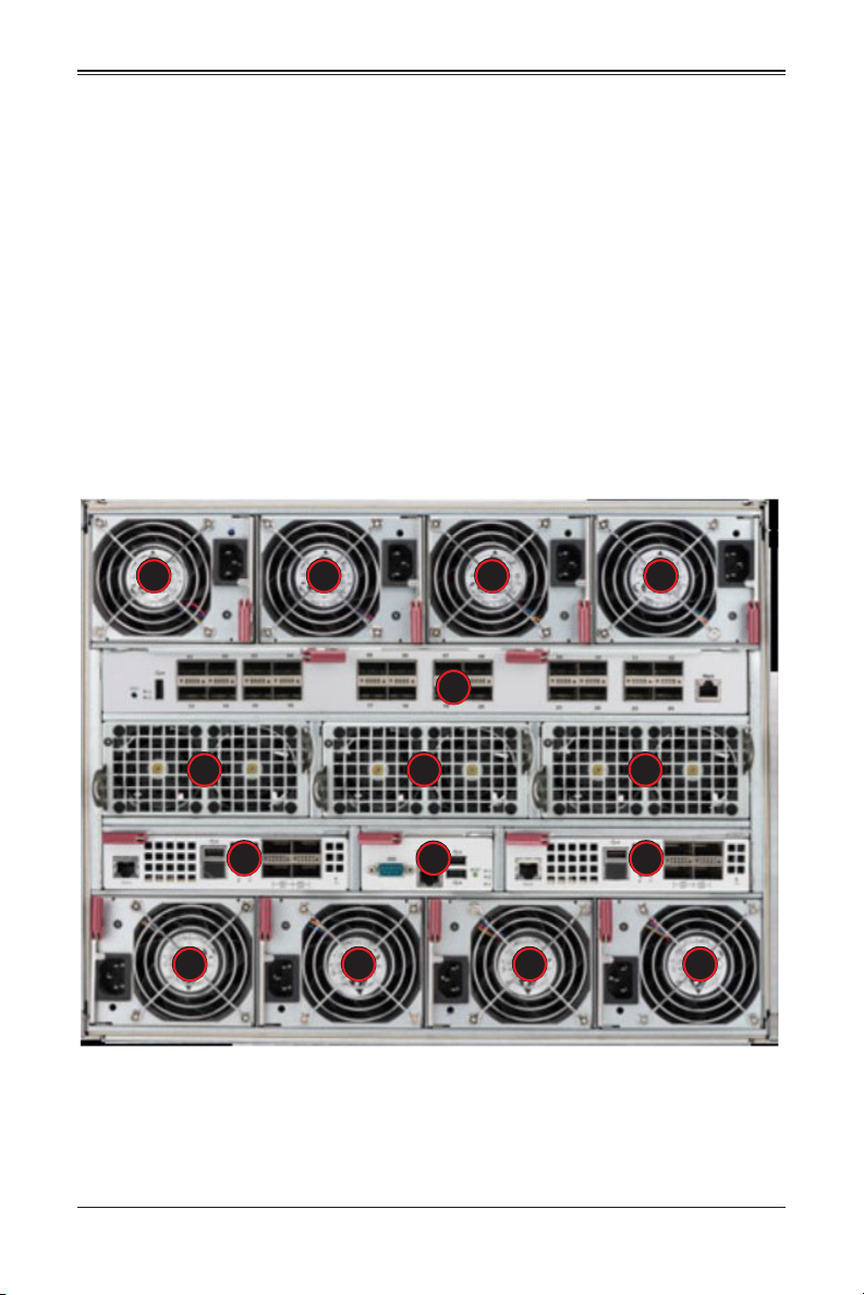
Figure 4-1. 8U 820C Enclosure with 100G Switch: Rear View
5555
3
4 44
1 1
5 5 5 5
2
4-1

8U SuperBlade User’s Manual
Figure 4-2. 8U 820C Enclosure with 2x25Gand 2x1/10G Switches: Rear View
5555
2
11
4 44
1 1
2
5 5 5 5
Table 4-1. Typical 8U Blade System Module Configuration: Rear View
Item# Description
1
2 CMM (Chassis Management Module) (x1 standard or x2 optional per enclosure)
3
4 Dual System Fan Modules
5 2200W Power Supplies (x4 required, x4 optional depending upon system requirements)
These bays can hold any of the following: 1Gb Ethernet Switch Module, 1Gb Pass-through
Module, a 1/10Gb Ethernet Switch Modules or a 25G Ethernet Switch
These triple-wide bays can contain either a 100Gb InfiniBand Switch or an Intel 100Gb
Omni-Path switch
NOTE: When setting up a bay, the single wide bay is for 10G/25G switches, while the triple
wide bay uses 100G switches for the 8U SuperBlade system.
4-2

Chapter 4: System Modules
4-1 Chassis Management Module
The Chassis Management Module (CMM) (Figure 4-3) is a required module in a blade
system. This “command” module communicates with the blade units, the power supplies
and the blade switches. Used in conjunction with the Web Interface or IPMI View
management software, the CMM provides administrator control over individual blade
units, power supplies, cooling fans and networking switches and monitors onboard
temperatures, power status, voltage levels and fan speeds. The standard CMM module
for the 8U SuperBlade system is the MBM-CMM-FIO or MBM-CMM-001.
NOTE: Using the MBM-CMM-FIO in the enclosure allows the use of the two front mounted
RJ45 ports on the enclosure, however using the MBM-CMM-001 does not allow these ports
to function.
The CMM provides a dedicated, local and remote KVM (keyboard/video/mouse)
connection over an out of band TCP/IP Ethernet network during any server state
(functioning, blue-screen, powered down, BIOS and so on). It also supports Virtual
Media (VM) redirection for CD, floppy and USB mass storage devices and configures
such information as the switch IP addresses. A summary of CMM features is shown in
Table 4-3.
Figure 4-3. Chassis Management Module MBM-CMM-FIO
7 4 6
3
2
1
5
Table 4-2. MBM-CMM-FIO Module Interface
Item# Description
1 Power LED
2 Fault LED
3 Information LED
4 USB Ports
5 IPMI Port
6 Ethernet Ports
7 Reset Button
8 Module Release Handle
4-3

8U SuperBlade User’s Manual
Table 4-3. MBM-CMM-FIO Module Features
Feature Description
Management Capabilities Can manage 10 to 20 blade units, network modules and 8 power supplies
Ports
Basic Functions Supported
System Management System management interface provided via dedicated LAN
Power Consumption Approximately 20W
Operating System Firmware (upgradable)
Figure 4-4. Chassis Management Module MBM-CMM-001
Two Ethernet ports, one IPMI Ethernet port and two USB ports (for debug
only)
Remote KVM, remote storage, Serial-over-LAN (SOL), blade monitoring
and control
7 4 5
3
2
1
Table 4-4. MBM-CMM-001 Module Interface
Item# Description
1 Power LED
2 Fault LED
3 Information LED
4 USB Ports
5 Ethernet Ports
6 Serial Port
7 Reset Button
8 Module Release Handle
6
8
4-4

Chapter 4: System Modules
Table 4-5. MBM-CMM-001 Module Features
Feature Description
Management Capabilities Can manage 10 to 20 blade units, network modules and 8 power supplies
Ports Two Ethernet ports, one serial port and two USB ports (for debug only)
Basic Functions Supported
System Management
Power Consumption Approximately 20W
Operating System Firmware (upgradeable)
Remote KVM, remote storage, Serial-over-LAN (SOL), blade monitoring
and control, switch, PWS, monitor, thermal, redundant based on specific
enclosure model.
System management interface provided via dedicated LAN, switch, PWS,
monitor, thermal, and is redundant based on the specific enclosure model.
Module Redundancy
A blade system must have one CMM and may have two for redundancy is offered only
on a specific enclosure model, which has the hardware capability to incorporate two
CMM's on one backplane. Since the CMM uses its own processor, all monitoring and
control functions are carried out regardless of the operation or power status of the blade
units. CMM modules can only be installed in the upper and/or lower right module bays.
Determining Master/Slave Modules Status
When a blade system has two CMM modules, they are assigned a master/slave status.
This is done automatically with the default primary CMM specified for per each
enclosure, while there will be no redundant in certain enclosures.
If the master CMM is powered down or removed (or is being reset by its user), the
second (slave) CMM module will then immediately be assigned as the master. The
redundant CMM mode is only offered on specific chassis models. The slave uses the
previous master IP config in case of a fail over.
NOTE: The Slave CMM keeps the same log/status as the Master CMM and uses the
previous master IP config.
CMM Module Installation
Use this procedure to install the MBM-CMM-FIO or MBM-CMM-001 CMM module to the
8U SuperBlade chassis. Make sure the cover to the module has been installed before
proceeding. Follow the anti-static precautions described in Chapter 2.
Installing the Module:
1. Remove the dummy cover from the bay you want to place the module in.
2. Place the module's release handle in the open position.
3. Slide the module into the module bay until it stops.
4. Push the release handle to the closed position.
4-5

8U SuperBlade User’s Manual
5. After the module has been installed and the handle locked, it will turn on and a
POST test will run to verify it is working properly.
Removing the Module:
1. Pull out the release handle to the open position.
2. Pull the module out of the bay.
3. Replace immediately with another module or with a dummy module cover to
maintain airflow integrity.
Configuring the CMM
To access/configure the CMM, you first have to configure the IP settings of the CMM
depending on you network environment. The below procedure for this configuration just
serves as a reference for getting the CMM setup. If your system has Linux OS, please
follow similar instructions to get the CMM setup.
The CMM access topology is as follows:
DHCP Access:
1. Connect a network cable to the CMM module.
2. The system should boot into the default Fail Over mode. The DHCP mode will
appear on the CLI mode screen.
3. If the system fail over and CLI is not active, it will proceed to the next default IP of
CMM at https//192.168.100.100.
4. If the CMM cannot enter the default IP, then an RJ45/USB cable can be connected
from the CMM's RJ45 Ethernet LAN Port to the Desktop Host using the USB Port in
Serial Port mode with a speed set at 115200. The DHCP IP can be manually set at
the same subnet-mask for gateway access at 192.168.100.100.01.
Default IP Access:
1. Connect network cable to the network port at CMM.
2. At system Prompt, https://192.168.100.100
Requirements are:
• Computer system with LAN (RJ45) port
• RJ -45 Ethernet cable
The default IP of the CMM is https://192.168.100.100. Configure the Computer system
(connected through Ethernet-LAN to the CMM) to the same address range (for example
https://192.168.100.101). The default mode is the Fail Over mode. If the DHCP fails,
then the CMM will automatically default to the IP address of the CMM.
Configuring the CMM in Windows OS:
1. Go to START CONTROL PANEL NETWORK CONNECTIONS
2. Right-click on LAN to view properties.
4-6

Chapter 4: System Modules
3. Choose “Internet Protocol (TCP/IP)” under the GENERAL tab and click on
PROPERTIES (see Figure 4-5).
Figure 4-5. Choose Internal Protocol
4. Manually configure the IP address of the computer system to be in the same
address range as the CMM (see Figure 4-6).
Example:
• IP address: https://192.168.100.101
• Subnet Mask: 255.255.255.0
• Default Gateway: 192.168.100.1
Figure 4-6. Manually Configure the IP Address
5. Once the IP address for the computer system is configured, the CMM can be
accessed through the web browser by entering the default IP address
192.168.100.100 of the CMM into the browser’s address bar.
4-7

8U SuperBlade User’s Manual
6. Now, the IP address, subnet mask and default gateway of the CMM can be changed
according to the network environment (see Figure 4-7). Please refer to the
Web-based Management Utility User’s Manual for more information.
Figure 4-7. Changing Settings
WARNING: Don't change any other setting, unless you are familiar with it.
NOTE: The above screens are examples for purposes of demonstrating this procedure. The
screens you actually view may or may not appear the same as those shown above.
4-8

Chapter 4: System Modules
CMM Functions
The following sections describe local functions and remote functions of the CMM. With
only minor exceptions, all of the remote functions can be performed by one of three
mechanisms: web-based access to the CMM module, access to the CMM using
IPMIview, a client tool implemented in Java, or via IPMItool commands (DOS
commands or shell scripted commands).
When the web based browser is used, the CMM acts as a web server, requiring a higher
bandwidth connection to the CMM. If there are any bandwidth constraints, IPMI will
provide a superior experience. Additionally, since graphical updates are provided by
client-side Java, IPMIview can also be a superior user experience.
IPMItool on the other hand can provide the ability to issue similar/identical commands to
many 8U SuperBlade enclosures/CMM’s to manage all of them in a similar way.
Remote KVM over IP
Remote KVM over IP is independent from local KVM (although local KVM can operate in
parallel with Remote KVM). Remote KVM encrypts all communication between the
remote user and the CMM.
To Use: Remote KVM over IP is initiated with the management software (IPMI View or
Web-based utility). Attach the LAN cable to the LAN port on the CMM module then refer
to "Web-based Management Utility" on page 4-12 to login and use either utility.
Remote Storage (Virtual Media)
The Remote Storage function allows the user to connect to a remote storage device
(such as a floppy, hard disk, or USB storage device) and access the device as if it were
local. This can be used not only to read and write to remote storage devices but to load
an operating system from a remote drive.
Serial Over LAN (SOL)
Serial Over LAN allows you to redirect the input and output of a serial port via IPMI in
order to manage blade modules from a remote location.
To Use: Serial Over LAN can be activated via the Web-based Management utility. See
the Web-based Management Utility User’s Manual for the procedure to initiate SOL.
Monitoring Functions
Used in conjunction with IPMI or the Web-based Management utility, the CMM module
can monitor and provide information on the hardware health of the blade modules and
the system as a whole. In addition to the monitoring functions, you can remotely power
on, power off or reboot a system.
Health information includes:
• Temperature levels
• Fan speeds
4-9

8U SuperBlade User’s Manual
• Voltage levels
• Power status
Power Consumption Management
The CMM module’s firmware can also control all power on/off activity in the whole blade
system. This is done by using the Power button, onboard BMC or from any other use of
remote management software.
Once a blade module is installed in the enclosure the installed CMM immediately
receives information on the rated Max Power Consumption value of the new blade
module. The CMM then calculates whether there is enough power for this new blade
module by comparing the Max Power Consumption value of the new blade module with
the calculated Remaining Power value of the system.
If there is enough power, the CMM will power on the blade. However if there is not
enough power in the blade system, then the new blade module is not powered on and
the front panel LED on the enclosure will blink.
After the blade is powered on, the CMM then collects the actual power consumption of
this individual blade and updates the calculated Remaining Power value for the system.
The CMM also reserves power for all the networking and chassis management modules
installed on the system.
WARNING: One CMM module must be running to control the power systems and prevent
overloading.
4-10

Chapter 4: System Modules
USB Ports and Reset Button
The USB Ports and Reset Button on the CMM are described below.
Figure 4-8. USB Ports on CMM
MBM-CMM-FIO
MBM-CMM-001
USB Ports
USB Ports
Reset Button
Reset Button
USB Ports
The USB ports on both CMM modules are shown in Figure 4-8. They are only used for
debugging purposes and not for communication with your system.
4-11

8U SuperBlade User’s Manual
Reset Button
The Reset button located on the front of the CMM module is used to reset the following
software settings to their defaults:
Table 4-6. CMM Reset Settings
Software Setting Default
User Name and Password Reset to ADMIN and ADMIN (case sensitive)
IP Address Reset to https://192.168.100.100
Gateway Address Reset to 0.0.0.0
Subnet Mask Reset to 255.255.255.0
To reset the CMM to factory defaults, press and hold the Reset button for five seconds.
Firmware
The firmware for the CMM switch resides in the module. This firmware can be updated
with the web-based management utility.
Within the utility, go to the MAINTENANCE > UPDATE FIRMWARE screen in the Web-based
Management Utility. Here you can enter the name of the firmware you want to update or
click on BROWSE to select the firmware file. Finish by clicking the UPLOAD button.
NOTE: This process is not reversible once the firmware is updated, so proceed with caution.
It might take a few minutes to complete this procedure.
Web-based Management Utility
System management may be performed with either of three software packages:
IPMIview, SMCIPMItool or a Web-based Management Utility. Any of these utilities are
designed to provide an administrator with a comprehensive set of functions and
monitored data to keep tabs on the system and perform management activities.
The Web-based Management Utility is a web-based interface that consolidates and
simplifies system management for Supermicro 8U SuperBlade systems. The
Web-based Management Utility aggregates and displays data from the CMM module.
The Web-based Management Utility provides the following key management features:
• Enables IT administrators to view in-depth hardware configuration and status
information using a single intuitive interface.
• Provides an OS-independent, remote graphical console.
• Allows remote users to map local media (floppy, removable disks and hard drives)
or ISO images on a shared network drive to a blade server.
4-12

Chapter 4: System Modules
Supported Browsers
The following browsers have been tested for use with the Web-based Management
Utility. It is recommended that you use the most current revision of the browser you
choose. The minimum browser revisions supported by the Web-based Management
Utility are shown below:
• Internet Explorer 7
• Firefox 2.0.0.7
• Netscape 9.03b
Network Connection/Login
To log into the Web-based Management Utility:
1. Launch a web browser.
2. In the address field of the browser, enter the IP address that you assigned to the
system and hit the <ENTER> key.
3. When the browser makes contact with Supermicro’s Chassis Management Module,
enter your username and password, then click LOGIN.
4. The WEB-BASED MANAGEMENT UTILITY HOME PAGE will then display as shown in
Figure 4-9.
Address Defaults
Table 4-7 shows the default addresses that are initially set for the CMM. Afterwards, you
can change these values within the program (see the Web-based Management Utility
User’s Manual M for more details).
Table 4-7. Address Defaults
Default Description
Default IP Address https://192.168.100.100
Default Gateway Address 0.0.0.0
Default Subnet Mask 255.255.255.0
Default username ADMIN
Default password ADMIN
a
a. Note: The web address must be entered as https://
192.168.100.100 in the web browser. Entering only http:// gives you
instead an address error.
4-13

8U SuperBlade User’s Manual
Home Page
Figure 4-9 displays the WEB-BASED MANAGEMENT UTILITY HOME PAGE and its controls.
Figure 4-9. Home Page
NOTE: For more information on the Web-based Management Utility, and a description of its
controls, see the Superblade Web-based Management Utility User’s Manual for more
details.
4-14

Chapter 5: Power Supply Modules
Chapter 5
Power Supply Modules
The 8U SuperBlade enclosure comes standard with one CMM module (see the
Chapter 4 for details on the CMM module) and either two or four power supplies. See
Appendix A for summary specification details on the power supplies available to the 8U
SuperBlade enclosure.
5-1 Power Supply Modules
The minimum amount of modules required to power the system depends upon the full
complement of blade units installed into an enclosure and the type of switches installed
in the enclosure. An LED on the back of a power supply will be amber when AC power is
present and green when the power is on.
When installing only a few power supplies in the enclosure, they should be installed first
in the lower rather than the upper power bays. This is to provide increased airflow
across the memory modules within each blade module.
The 2200W power supply modules require a 200-240V AC input and a C20 socket,
which requires a power cord with a C19 connector.
Supermicro's high-efficiency blade system power supplies deliver continuous redundant
power up to 94% peak efficiency. Each power supply module includes a management
module that monitors the power supplies and the power enclosure
The features of these power supplies are shown below.
Table 5-1. Amperage Draw Specifications for the PWS-2K21A-BR Power Supply
Watts Low Volts High Volts Low Amps High Amps
1200W 100 127 11 14
1980W 220 230 9.8 10
2090W 230 240 9.8 10
1800W 200 220 9.5 10
2200W (UL/cUL only) 220 240 11 12
2090W (UL/cUL only) 180 220 11 14
5-1

8U SuperBlade User’s Manual
Figure 5-1. PWS-2K21A-BR Power Supply
Table 5-2. PWS-2K21A-BR Power Supply Features
Feature Description
Output 2200W/2090W/1980W/1800W/1200W
Type Redundant Module (N+1/N+N)
+12V
+12VSB 2A
PFC Yes
Peak Efficiency 96%+ (Titanium Level)
Input AC Range
Operating Conditions
Fan Type 80x80mm counter rotating fan
Dimensions (LxWxH) 245.3 x 106.5 x 84mm
183.33A (2200W), 174.17A (2090W), 165A (1980W), 150A (1800W) or
100A (1200W)
100-127V (1200W), 200-220V (1800W), 220-230V (1980W), 230-240V
(2090W), 200-220V (2090W for UL & cUL) or 220-240V (2200W for UL &
cUL)
Temp: 0 to 50 C
Humidity: 5 to 95% RH
5-2

Chapter 5: Power Supply Modules
Figure 5-2. PWS-1K20B-BR Battery Backup Power (BPP) Module
Table 5-3. PWS-1K20B-BR Battery Backup Power (BPP) Module Specifications
Feature Description
Total Output Power 1200W
Input 11.2 to 12.9VDC
Output 12V, 12VSB
Form Factor MicroBlade
Dimensions 245.3 x 106.5 x 84-mm
Battery Cell Capacity 68W/hr
Redundant N+1, N+N
I2C Remote Monitoring FRU/Smart Battery I2C
+12V Output 100A
12VSB Output 2.5A
Efficiency Online mode battery power consumption less than 5W
Discharge Duration 1200W for 35 Seconds
Cell Chemistry Lithium-Ion
Cooling Internal 80 x 80-mm colling fan
Operating Temperature 5°C - 50°C
5-3

8U SuperBlade User’s Manual
Table 5-4. PWS-1K20B-BR BPP Module Estimated Runtime
Power Load Installed BPP Modules Discharge Duration
1000W 4 180 Seconds
2000W 4 120 Seconds
3000W 4 60 Seconds
4000W 4 35 Seconds
4800W 4 35 Seconds
Under typical conditions, the above is the estimated runtime for the BPP modules. The
runtime can be extended by adding additonal BPP modules to a system.
Table 5-5. Chassis Compatible with the BPP
Model Output Power Capacity SBE-820CB-422 SBE-820JB-422
PWS-1K208-BR 1200W 68W/hour Up to 4 Up to 4
Power Supply Failure
If a power supply or a fan in a power supply fails, the system management software will
notify you of the situation. In either case, you will need to replace the power supply
module with another identical one.
NOTE: Refer to www.supermicro/products/superblade for possible updates on part
numbers.
Installing a Power Supply
1. Insert a replacement unit into the empty power bay with the handle to the left.
WARNING: This left/right orientation depends on the power supply’s top or bottom location.
If you inadvertently put a power supply upside down in the lower slots, it can be VERY
difficult to remove the power supply.
2. Push unit all the way in until it is firmly seated.
3. Push the handle back into the closed position until it clicks into the locked position.
4. Move the locking clip away from the socket and reconnect the power cord.
Removing a Power Supply
First, make sure the power supply has been shut down. You can remove power from a
power unit via your system management software.
1. Remove the power cord from the power supply unit.
2. Release the locking clip to unlock the power supply module.
5-4
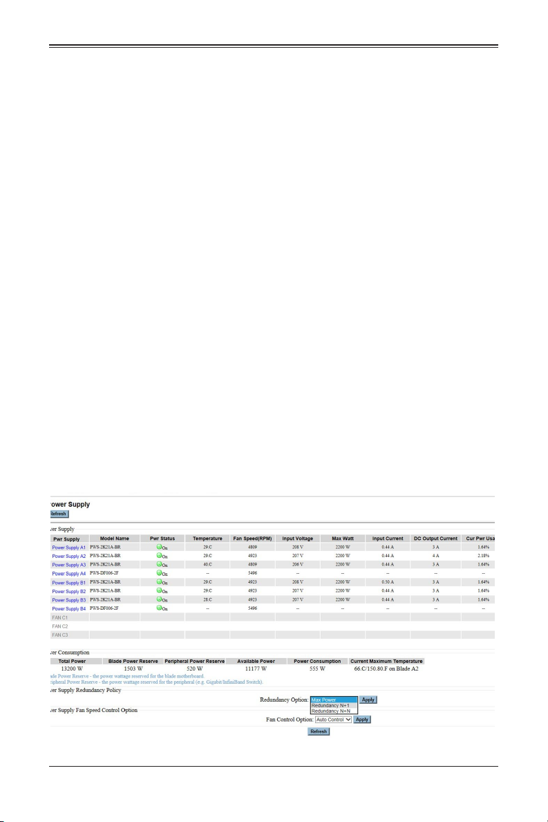
Chapter 5: Power Supply Modules
3. Pull out the handle and remove the unit: the two-piece handle locks into the closed
position. To release the handle, squeeze together the two metal plates of the handle
with your thumb and fingers and then pull out.
5-2 Redundant Power Supplies
Each blade enclosure can hold up to four power supplies. Installing all four power
supplies may provide you with redundant power – depending upon the number of blades
in the enclosure, the model and power level of the power supplies installed and the
power load from modules in your system. In most blade enclosure systems power
supplies may be redundant and therefore provide backup in case of power supply
failure. The configuration for power redundancy is created using the IPMIView
application tool for the system.
For purposes of denoting the amount of redundancy, a server system has N main power
supplies to support the whole system working, with a “+” number after the N denoting
the number of redundant power supplies. Hence, if there is one power supply for
redundancy in a system that has the feature of “redundant power”, the total of power
supplies for that server system is denoted as N+1.
For example, suppose a 10-blade system has four 2200 Watt Power Supply Units
(PSU), for a total power supply of 8800 Watts. The maximum power usage of each
blade is 375 Watts for a total power demand of 3750 Watts to run the whole system. So
in this example there are effectively two redundant power supplies (N+1) over what is
needed to power the blades in the system.
In the IPMIView tool you can set the priority (default CPU power usage) of each blade
first before any PSU fails (0%->shut down, 50%->throttling, 100%->Running). See
Figure 5-3 below for an example.
Figure 5-3. Power Supply Status
5-5

8U SuperBlade User’s Manual
Therefore the following redundancies apply to your system when, as an example,
2200W power supplies fail.
• If one PSU fails, then you have 6600 Watts available. The CMM will detect the
remaining power left for the whole system. But because the total blade power usage
is only 3750 Watts, every blade can still work properly.
• If 2 PSUs fail, then only 4400 Watts are left available to support the blade power
usage. The system can still support all ten blades running in it.
• If 3 PSUs fail, then the remaining 2200 Watts available cannot support the whole
system. Therefore the CMM will start to shut down or throttle down the load in order
to keep blades running based upon the priority settings that were made for each
blade using the IPMIView application until the load is enough to power the
remaining blade modules.
5-3 Power Supply Fans
Each power supply unit has two to four rear fans. These fans are not hot-swappable. If
one fails, the power supply will continue to operate but you should replace the power
supply unit at the earliest opportunity. If two or more fans fail, the power supply unit will
shut down and the LED on the back will turn amber.
5-6

Appendix A
System Specifications
A-1 Enclosure Specifications
Table A-1. 8U Enclosure Specification Features
Enclosure
Blade Module Support
System Cooling
Power Supplies (modules
required varies)
System Input Requirements
Thermal Range
NOTE: Up to 8x (N+1 or N+N redundant) 2200W Titanium certified (96% efficiency) AC
power supplies or 2000W DC power supplies battery back-up option on SBE-820C/E-422
PDU specs and requirements for rack.
SBE-820C-822/622 rack mount blade enclosures
Dimensions: (WxHxD) 12.2" x 17.6" x 29" in. (309.8 x 447 x 736.6 mm)
Up to either 10 full-height, 4-socket or 20 half-height, 2 socket hot-plug
blade modules
Three twin-PWM fan modules in the rear chassis. In addition, up to four (4)
optional cooling fan modules can be used in place of four power supplies
can be mounted in an enclosure.
Rated Output Power: 2200W (Part# PWS-2K21-BR, C-20 type socket)
power supplies
Rated Output Voltages: +12V (183A), +12Vsb (2A) for 2200W; +12V
(174A), +12Vsb (2A) for 2090W; +12V (165A), +12Vsb (2A) for 1980W;
+12V (150A), +12Vsb (2A) for 1800W; +12V (100A), +12Vsb (2A) for
1200W
Power Supply Model Numbers:
• PWS-2K21A-BR (for the SBE-820C-822 enclosure)
• PWS-DF006-2F (for the SBE-820C-622 enclosure)
• PWS-DF005-2F (for the SBE-820C-42 enclosure)
AC Input Voltage: 220~240V AC auto-range for 2200W; 230~240V AC
auto-range for 2090W; 220~230V AC auto-range for 1980W; 200~220V
AC auto-range for 1800W; 100-127V AC auto-range for 1200W
Rated Input Current: 12A-11A for 2200W; 14-11A for 2090W; 10-9.8A for
1980W; 10-9.5A for 1800W; 14-11A for 1200W
Rated Input Frequency: 50 to 60 Hz
Supermicro’s new 8U SuperBlade Enclosure has a wide thermal support
range to incorporate a significant range of CPU TDP, this can range from
85W, 105W, 125W, 130W, 140W, 150W, 155W, 165W and 205W.
A special heatsink is required for the gold CPU with TDP ranging from
165W-200W. Extra wide heatsinks are required for the 205W platinum
CPU.
For further details, please check with thermal specifications and advisory
for conditional thermal support of 15-32° degree ambient and 10-35°
degree ambient temperatures. The 8U system will not support 5-45°
degree ambient temperatures.
:
A-1

8U SuperBlade User’s Manual
A-2 Environmental Specifications
Table A-2. Environmental Specification Features
Operating Temperature: 10º to 35º C (50º to 95º F)
Operating Environment
Regulatory Compliance
Safety
Non-operating Temperature: -40º to 70º C (-40º to 158º F)
Operating Relative Humidity: 8% to 90% (non-condensing)
Non-operating Relative Humidity: 5 to 95% (non-condensing)
Electromagnetic Emissions:
FCC Class A, EN 55022 Class A, EN 61000-3-2/-3-3, CISPR 22 Class A
Electromagnetic Immunity:
EN 55024/CISPR 24, (EN 61000-4-2, EN 61000-4-3, EN 61000-4-4, EN
61000-4-5, EN 61000-4-6, EN 61000-4-8, EN 61000-4-11)
EN 60950/IEC 60950-Compliant, UL Listed (USA), CUL Listed (Canada),
TUV Certified (Germany), CE Marking (Europe)
California Best Management Practices Regulations for Perchlorate
Materials: This Perchlorate warning applies only to products containing CR
(Manganese Dioxide) Lithium coin cells. “Perchlorate Material-special
handling may apply. See www.dtsc.ca.gov/hazardouswaste/perchlorate for
details.
A-3 Address Defaults
Table A-3. Address Defaults
IP Address: 192.168.100.100
CMM Module
GbE Switch
Gateway Address: 0.0.0.0
Subnet Mask: 255.255.255.0
User Name and Password: ADMIN and ADMIN (case sensitive)
IP Address: 192.168.100.102
Gateway Address: 192.168.100.1
Subnet Mask: 255.255.255.0
A-2
A-4 Power Supply Power Calculations
Table A-4. Power Supply: Power Calculations (PWS-2K21A-BR)
Calculation Value
Watts 2200
Volts (High/Low) 240/220
Amps (High/Low) 12/11
Efficiency (High) 96%
Power Factor (High) 98%
10% Reserve (High) 1.5
10% Reserve (Low) 1.3
Amps (Total) 11@240 volts
Table A-5. Power Supply: Power Calculations (PWS-1K20B-BR)
Calculation Value
Watts 1200
Volts (High/Low)
Amps (High/Low)
Efficiency (High) 94%
Power Factor (High) 98%
10% Reserve (High) 1.5
10% Reserve (Low) 1.3
DC Output 12V: 12Vsb
DC Input: 11.2 to 12.9Vdc
+12V Output: 100A
12Vsb Output: 2A
:
A-3

8U SuperBlade User’s Manual
Notes
A-4

Disclaimer
The products sold by Supermicro are not intended for and will not be used in life support
systems, medical equipment, nuclear facilities or systems, aircraft, aircraft devices,
aircraft/emergency communication devices or other critical systems whose failure to
perform be reasonably expected to result in significant injury or loss of life or
catastrophic property damage. Accordingly, 8U SuperBlade disclaims any and all
liability, and should buyer use or sell such products for use in such ultra-hazardous
applications, it does so entirely at its own risk. Furthermore, buyer agrees to fully
indemnify, defend and hold Supermicro harmless for and against any and all claims,
demands, actions, litigation, and proceedings of any kind arising out of or related to
such ultra-hazardous use or sale.
:

8U SuperBlade User’s Manual
 Loading...