

Supermicro 8060 User Manual
®
SUPERSERVER 8060
USER’S MANUAL
1.0
SUPER
RESETALARM
S
UPERMICR
R
SuperServer 8060

The information in this User’s Manual has been carefully reviewed and is believed to be
accurate. The vendor assumes no responsibility for any inaccuracies that may be
contained in this document, makes no commitment to update or to keep current the
information in this manual, or to notify any person or organization of the updates.
Please
Note: For the most up-to-date version of this manual, please see our
web site at www.supermicro.com.
SUPERMICRO COMPUTER reserves the right to make changes to the product described in
this manual at any time and without notice. This product, including software, if any, and
documentation may not, in whole or in part, be copied, photocopied, reproduced, translated
or reduced to any medium or machine without prior written consent.
IN NO EVENT WILL SUPERMICRO COMPUTER BE LIABLE FOR DIRECT, INDIRECT,
SPECIAL, INCIDENTAL, SPECULATIVE OR CONSEQUENTIAL DAMAGES ARISING FROM
THE USE OR INABILITY TO USE THIS PRODUCT OR DOCUMENTATION, EVEN IF
ADVISED OF THE POSSIBILITY OF SUCH DAMAGES. IN PARTICULAR, THE VENDOR
SHALL NOT HAVE LIABILITY FOR ANY HARDWARE, SOFTWARE, OR DATA STORED
OR USED WITH THE PRODUCT, INCLUDING THE COSTS OF REPAIRING, REPLACING,
INTEGRATING, INSTALLING OR RECOVERING SUCH HARDWARE, SOFTWARE, OR
DATA.
Any disputes arising between manufacturer and customer shall be governed by the laws of
Santa Clara County in the State of California, USA. The State of California, County of
Santa Clara shall be the exclusive venue for the resolution of any such disputes.
Supermicro's total liability for all claims will not exceed the price paid for the hardware
product.
Unless you request and receive written permission from SUPER MICRO COMPUTER, you
may not copy any part of this document.
Information in this document is subject to change without notice. Other products and
companies referred to herein are trademarks or registered trademarks of their respective
companies or mark holders.
Copyright © 2000 by SUPER MICRO COMPUTER INC.
All rights reserved.
Printed in the United States of America.

Preface
About This Manual
This manual is written for professional system integrators and PC technicians. It provides information for the installation and use of the SuperServer 8060. Installation and maintainance should be performed by experienced technicians only.
The SuperServer 8060 is a high-end quad processor 4U rackmount server
based on the SC860 4U rackmount server chassis and the S2QE6, a quad
processor motherboard that supports up to four Pentium III/II Xeon processors and 16 GB SDRAM main memory.
Manual Organization
Chapter 1: Introduction
The first chapter provides a checklist of the main components included with
the server system and describes the main features of the SUPER S2QE6
mainboard and the SC860 chassis, which make up the SuperServer 8060.
Chapter 2: Server Installation
This chapter describes the steps necessary to install the SuperServer 8060
into a rack and check out the server configuration prior to powering up the
system. If your server was ordered without processor and memory components, this chapter will refer you to the appropriate sections of the
manual for their installation.
Chapter 3: System Interface
Refer here for details on the system interface, which includes the functions
and information provided by the control panel on the chassis as well as
other LEDs located throughout the system.
Chapter 4: System Safety
You should thoroughly familiarize yourself with this chapter for a general
overview of safety precautions that should be followed when installing and
servicing the SuperServer 8060.
iii
Preface

SUPERSERVER 8060 Manual
iv
Chapter 5: Advanced Motherboard Setup
Chapter 5 provides detailed information on the motherboard, including the
locations and functions of connections, headers, jumpers, DIP switches and
IRQs. Refer to this chapter when adding or removing processors or main
memory and when reconfiguring the motherboard.
Chapter 6: Advanced Chassis Setup
Refer to Chapter 6 for detailed information on the 4U rackmount server
chassis. You should follow the procedures given in this chapter when
installing, removing or reconfiguring SCSI or peripheral drives and when
replacing system power supply units and cooling fans.
Chapter 7: BIOS
The BIOS chapter includes an introduction to BIOS and provides detailed
information on running the CMOS Setup Utility.
Appendix A: BIOS Error Beep Codes and Messages
Appendix B: Post Diagnostic Error Messages
Appendix C: List of Figures
Appendix D: System Specifications
v
Manual Or
g
anization
Introduction
Chp1
Installation System
Interface
System
Safety
Motherboard
Details
Chassis
Details
BIOS and
Setup Routine
Chp3Chp2
Chp5
Chp4
Chp6
Appendices
Overview
Chassis
Mainboard
Contact Info
Overview
Precautions
Setup
Rack
Installation
Overview
Switches
Cntrl Pnl LEDs
SCSI LEDs
Pwr Sply LEDs
MB LEDs
Static Sensitive
MB Installation
Cables
CPU Installation
MEC Install.
PCI Cards
MB Layout
Connectors
DIP Switches
Jumper
Settings
I/O Ports/IDE/
SCSI Conn.
IRQs
Static Sensitive
Control Panel
System Fans
Drive Bay Inst.
Power Supply
Chp7 App. A/B/C/D
Introduction
BIOS Features
Running Setup
Electrical Safety
General Safety
ESD Safety
BIOS Beep
Codes
Post Diag. Error
Messages
List of Figures
System Specs
Preface

SUPERSERVER 8060 Manual
vi
Table of Contents
Preface
About This Manual ...................................................................................................... iii
Manual Organization ................................................................................................... iii
Manual Organization (Flowchart)............................................................................. v
Chapter 1: Introduction to the SuperServer 8060
1-1 Overview ......................................................................................................... 1-1
1-2 Server Chassis Features.............................................................................. 1-2
1-3 Mainboard Features ....................................................................................... 1-4
1-4 Contacting Supermicro .................................................................................. 1-5
Chapter 2: Server Installation
2-1 Overview ......................................................................................................... 2-1
2-2 Unpacking the SuperServer 8060 ............................................................... 2-1
2-3 Preparing for Setup ....................................................................................... 2-1
Choosing a Setup Location .................................................................... 2-2
Rack Precautions ..................................................................................... 2-2
Server Precautions.................................................................................. 2-2
2-4 Installing the SuperServer 8060 into a Rack ............................................ 2-3
Identifying the Sections of the Rack Rails .......................................... 2-3
Installing the Chassis Rails ..................................................................... 2 - 4
Installing the Rack Rails .......................................................................... 2 - 4
Installing the Server into the Rack ........................................................ 2 -5
2- 5 Checking the Motherboard Setup ................................................................ 2-7
2-6 Checking the Drive Bay Setup ..................................................................... 2-9
Chapter 3: System Interface
3-1 Overview ......................................................................................................... 3-1
3-2 Control Panel Switches................................................................................. 3-1
Power ........................................................................................................ 3-1
Alarm .......................................................................................................... 3-1
Reset .......................................................................................................... 3-1
3-3 Control Panel LEDs ........................................................................................ 3-2
Power ........................................................................................................ 3-2
NIC .............................................................................................................. 3-2
HDD ............................................................................................................ 3-2
PWR Fault.................................................................................................. 3-2

Fan Fail...................................................................................................... 3-3
Overheat ................................................................................................... 3-3
SCA Channel ............................................................................................ 3-3
3- 4 SCSI Drive Carrier LEDs ............................................................................... 3-4
3-5 Power Supply LEDs ....................................................................................... 3-4
3- 6 Motherboard LED ............................................................................................ 3-4
Chapter 4: System Safety
4-1 Electrical Safety Precautions ........................................................................ 4-1
4-2 General Safety Precautions .......................................................................... 4-2
4- 3 ESD Precautions.............................................................................................. 4-3
Chapter 5: Advanced Motherboard Setup
5- 1 Handling the S2QE6 Motherboard ................................................................. 5 -1
5- 2 Motherboard Installation ................................................................................. 5 -2
5-3 Connecting Cables .......................................................................................... 5 -4
Connecting Data Cables .......................................................................... 5 -4
Connecting Power Cables....................................................................... 5-4
Connecting the Control Panel ................................................................. 5 - 5
5- 4 Installing Processors and DRMs ................................................................... 5 - 6
Removing the Pentium II/III Xeon Processors ...................................... 5-7
5- 5 Installing Memory in the MEC ........................................................................ 5-8
5- 6 Adding PCI Cards .......................................................................................... 5-11
Super S2QE6 Layout ............................................................................. 5-12
5-7 Connector Definitions ................................................................................... 5-14
Power Supply Connectors ................................................................... 5-14
Secondary Power Connector............................................................... 5-14
Power LED ............................................................................................... 5-14
Fan Fail LED............................................................................................ 5-14
IDE LED ..................................................................................................... 5-15
Power Fail LED ...................................................................................... 5- 15
PWR_ON .................................................................................................. 5-15
NIC_LED ................................................................................................... 5-15
Reset ........................................................................................................ 5-16
Chassis Intrusion ................................................................................... 5-16
Keyboard Lock ....................................................................................... 5-16
Extra Universal Serial Bus Connection .............................................. 5-17
Overheat LED ......................................................................................... 5- 17
Speaker ................................................................................................... 5- 17
Alarm Reset ............................................................................................ 5-18
vii
Table of Contents

SUPERSERVER 8060 Manual
viii
Fan Headers ........................................................................................... 5-18
Serial Ports ............................................................................................. 5-18
ATX PS/2 Keyboard and Mouse Ports ................................................ 5-19
Universal Serial Bus Connector .......................................................... 5- 19
Ethernet Port........................................................................................... 5-19
Wake-On-Ring ........................................................................................ 5-19
SLED ........................................................................................................ 5-20
5- 8 DIP Switch Settings ...................................................................................... 5-20
DIP Switch 1: Core/Bus Ratio .............................................................. 5-20
DIP Switch 2 ............................................................................................ 5-21
5- 9 Jumper Settings ............................................................................................. 5-21
Explanation of Jumpers ......................................................................... 5-21
Front Side Bus Speed ........................................................................... 5-21
Power Supply Fail Alarm Enable/Disable ........................................... 5-22
Overheat Buzzer Alarm Enable/Disable ............................................. 5-22
BIOS Select .............................................................................................. 5-22
Onboard LAN/NIC Enable/Disable......................................................... 5-23
LVD Channel A SCSI Termination Enable/Disable............................. 5-23
LVD Channel B SCSI Termination Enable/Disable ............................. 5-23
50-pin Legacy Channel B SCSI Termination Enable/Disable ........... 5-23
SCSI Enable/Disable................................................................................ 5-24
CMOS Clear.............................................................................................. 5-24
5-10 Port/Control Panel Connector Locations .................................................... 5-24
5-11 Parallel Port, Floppy/HDD and SCSI Connections .................................... 5-25
Parallel Port Connector ......................................................................... 5- 25
Floppy Connector ................................................................................... 5-25
IDE Connectors ...................................................................................... 5- 26
50-pin Legacy SCSI Connector ............................................................ 5-26
Ultra160 SCSI Connectors ..................................................................... 5-27
5-12 IRQs ................................................................................................................. 5-28
Chapter 6: Advanced Chassis Setup
6-1 Static-Sensitive Devices ................................................................................ 6-1
6-2 Control Panel .................................................................................................... 6-2
6-3 System Fans .................................................................................................... 6-4
System Fan Failure .................................................................................. 6-4
Replacing System Cooling Fans ............................................................ 6-5
Replacing System Exhaust Fans .......................................................... 6-6
6- 4 Drive Bay Installation/Removal ...................................................................... 6-6

Table of Contents
ix
Accessing the Drive Bays ..................................................................... 6-6
SCSI Drive Installation............................................................................. 6-7
CD-ROM and Floppy Drive Installation ............................................... 6-10
6-5 Power Supply Units ...................................................................................... 6-11
Power Supply Failure ........................................................................... 6-11
Replacing Power Units ......................................................................... 6-11
Chapter 7: BIOS
7- 1 Introduction....................................................................................................... 7 -1
7- 2 BIOS Features.................................................................................................. 7-2
7- 3 Running Setup.................................................................................................. 7-2
Standard CMOS Setup ............................................................................. 7 -4
Advanced CMOS Setup ........................................................................... 7 -5
Advanced Chipset Setup ........................................................................ 7-9
Power Management ................................................................................ 7-11
PCI/Plug and Play Setup ........................................................................ 7-13
Peripheral Setup...................................................................................... 7-16
Auto-Detect Hard Disks ........................................................................ 7-19
Change User/Supervisor Password.................................................... 7-19
Change Language Setting ..................................................................... 7-19
Auto Configuration with Optimal Settings .......................................... 7-19
Auto Configuration with Fail Safe Settings ....................................... 7-20
Save Settings and Exit .......................................................................... 7-20
Exit Without Saving ................................................................................. 7-20
Appendices:
Appendix A: BIOS Error Beep Codes and Messages ....................................... A - 1
Appendix B: AMIBIOS Post Diagnostic Error Messages ....................................B -1
Appendix C: List of Figures .................................................................................... C-1
Appendix D: System Specifications ...................................................................... D-1

Notes
SUPERSERVER 8060 User's Manual
x

Chapter 1
Introduction to the SuperServer 8060
1-1 Overview
The Supermicro SuperServer 8060 is a high-end quad processor, 4U
rackmount server that features some of the most advances technology
currently available. The SuperServer 8060 is comprised of two main subsystems: the SC860 4U rackmount chassis and the S2QE6 quad Pentium III/
II Xeon processor mainboard. Please refer to our web site for information
on operating systems that have been certified for use with the SuperServer
8060.
In addition to the mainboard and chassis, various hardware components
may have been included with your SuperServer 8060, as listed below.
l Up to four (4) Pentium III XeonTM processors*
l One (1) Memory Expansion Card (MEC) that supports up to 16 GB
SDRAM main memory
l One (1) 1.44" floppy drive
l One (1) slim CD-ROM drive
l One (1) Supermicro CD containing various drivers and utilities
l One (1) Control Panel PCB
l Rackmount hardware (with screws):
Two (2) rack rail assemblies
Four (4) brackets for mounting the rack rails to the rack
l Two (2) CPU Dual Retention Modules (DRMs) with screws
l One (1) CPU fan shroud
l One (1) SCA backpanel
l Four (4) SCA SCSI drive carriers
Chapter 1: Introduction
1-1

SUPERSERVER 8060 Manual
1-2
1-2 Server Chassis Features
The SuperServer 8060 is a high-end, scaleable 4U rackmount server platform designed with today's most state-of-the-art features. The following is
a general outline of the main features of the SC860 chassis.
System Power
A triple redundant power supply consisting of three 300W units to provide
600W of continuous power with 300W of backup. If any one of the three
power units fail you will be notified by alarm and LED, and the backup unit
will automatically activate. These are hot-plug units that can be replaced
without powering down the system.
SCSI Subsystem
The SCSI subsystem supports 4 80-pin SCA Ultra160 SCSI hard drives.
(Any standard 1" drives are supported. SCA = Single Connection Attachment.) The SCSI drives are connected to a SAF-TE compliant SCA
backplane that provides power, bus termination and configuration settings.
The SCSI drives are also hot-swap units. A RAID controller card can be
used with the SCA backplanes to provide data security.
Note: The operating system you use must have RAID support to enable the
hot-swap capability of the SCSI drives.
l SCSI Accessories
One (1) internal and one (1) external 68-pin Ultra160 SCSI cable w/o
active termination for SCA SCSI backplane
One (1) set of SCSI driver diskettes
One (1) SCSI manual
l Two (2) TMR-008 CPU slot terminator cards*
l Six (6) VRMs (Voltage Regulator Modules)
You should also have received this User's Manual and several Supermicro
diskettes, which contains various drivers and utilities.
*
Type and number depends upon the configuration ordered.
1-3
Chapter 1: Introduction
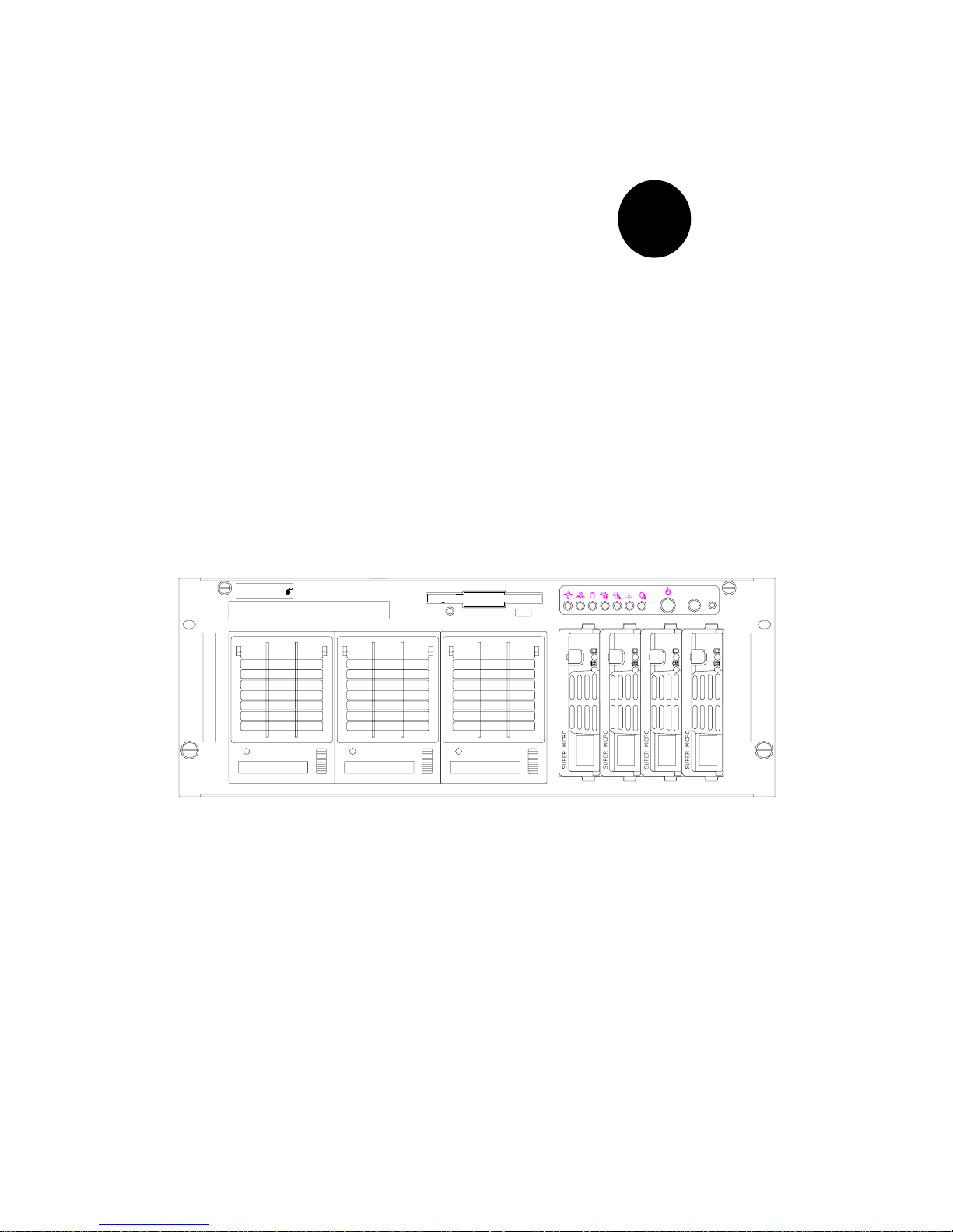
Control Panel
The SuperServer 8060's detailed control panel provides comprehensive
system monitoring and control. LEDs indicate network activity, power supply failure, fan failure, fan status, SCSI drive activity and failure and SCA
backplane overheat conditions. The control panel also includes a main
power button, a system reset button and an alarm reset switch.
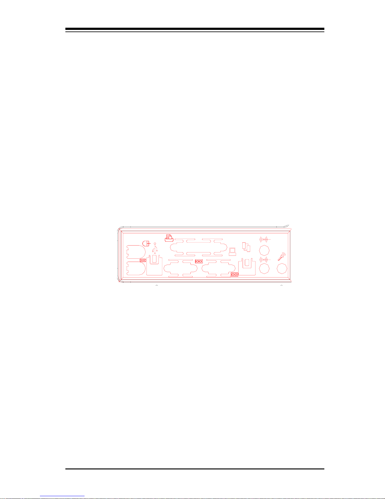
I/O Shield
The SC860 is a 4U rackmount, WTX form factor chassis. Its I/O shield
provides seven motherboard expansion slots, one COM port (the other is
internal), a parallel port, two USB ports, PS/2 mouse and keyboard ports, a
video port and an Ethernet port. (See Figure 1-1.)
Cooling System
The SC860 chassis has an innovative cooling design that includes four 9cm hot-plug system cooling (intake) fans and two 9-cm hot-plug exhaust
fans. All system fans (located between the drive bays and the motherboard) operate continuously. If one fails, an alarm is activated and the RPM
of the remaining fans increase to compensate and maintain sufficient airflow. A CPU air shroud is also included to concentrate cooling air around
the processors, which generate the most heat.
Figure 1-1. I/O Shield

SUPERSERVER 8060 Manual
1-4
1-3 Mainboard Features
At the heart of the SuperServer 8060 lies the S2QE6, a quad processor
motherboard designed to provide maximum performance in a four-way system. Below are the main features of the S2QE6.
Processors
The S2QE6 supports Pentium III and II 400-700 MHz Xeon 100 MHz FSB
processors in 1, 2, 3 and 4-way configurations. Future higher speed processors with a 100 MHz FSB are also supported. Please refer to the
support section of our web site for a complete listing of supported processors (http://www.supermicro.com/TechSupport.htm).
Memory
The MEC (Memory Expansion Card) included with your S2QE6 has 16 DIMM
slots that can support up to 16 GB of ECC registered DIMM. Module sizes of
128MB, 256MB, 512MB and 1 GB may be used to populate the MEC.
Onboard SCSI
Onboard SCSI is provided with an Adaptec AIC-7899 SCSI controller chip,
which supports dual channel, Ultra160 SCSI at a burst throughput rate of
160 MB/sec for each channel. The S2QE6 provides three SCSI ports: two
68-pin LVD Ultra160 connectors (on channels A and B) and one 50-pin
Legacy SCSI connector (shared with channel B.)
PCI Expansion Slots
The S2QE6 has a total of six PCI expansion slots that consist of two 64-bit
66 MHz slots and four 64/32-bit 33 MHz slots. The four 33 MHz slots are
backward compatible with 32-bit PCI cards. These PCI slots run on two
separate data buses to provide a total I/O bandwidth of 792 MB/sec.
ATI Rage XL PCI Graphics Controller
An onboard ATI graphics controller based on the Rage XL graphics chip is
integrated into the S2QE6. This onboard graphics controller includes 8 MB
of onboard memory and fully supports sideband addressing. This onboard
graphics package provides a bandwidth of up to 512 MB/sec over a 32-bit
graphics memory bus on the S2QE6.

1-5
Chapter 1: Introduction
1-4 Contacting Supermicro
Headquarters
Address: Super Micro Computer, Inc.
2051 Junction Avenue
San Jose, CA 95131 U.S.A.
Tel: +1 (408) 895-2001
Fax: +1 (408) 895-2008
E-mail: marketing@supermicro.com (General Information)
support@supermicro.com (Technical Support)
Web site: www.supermicro.com
European Office
Address: Super Micro Computer B.V.
Het Sterrenbeeld 28, 5215 ML,
's-Hertogenbosch, The Netherlands
Tel: +31 (0) 73-6400390
Fax: +31 (0) 73-6416525
E-mail: sales@supermicro.nl
support@supermicro.nl (Technical Support)
rma@supermicro.nl (Customer Support)
Onboard Controllers/Ports
An onboard IDE controller supports one floppy drive and up to four
UDMA/33 hard drives or ATAPI devices. Onboard I/O ports include two
COM ports, a parallel port, two USB ports, PS/2 mouse and keyboard ports,
a video (monitor) port and a 10/100 MB Ethernet port. The S2QE6 also has
an onboard ATI graphics controller (see above).
Other Features
Other onboard features that promote system health include eight voltage
monitors, a chassis intrusion header, auto-switching voltage regulators,
chassis and CPU overheat sensors, virus protection and BIOS rescue.

SUPERSERVER 8060 Manual
1-6
Notes
Chapter 2: Server Installation
2-1
Chapter 2
Server Installation
2-1 Overview
This chapter provides a quick setup checklist to get your SuperServer 8060
up and running. Following these steps in the order given should enable you
to have the system operational within a minimum amount of time. This quick
setup assumes that your SuperServer 8060 system has come to you with
the processors and memory preinstalled. If your system is not already fully
integrated with a motherboard, processors, system memory etc., please
turn to the chapter or section noted in each step for details on installing the
specific component.
2-2 Unpacking the SuperServer 8060
You should inspect the box the SuperServer 8060 was shipped in and note
if it was damaged in any way. If the server itself shows damage you
should file a damage claim with the carrier who delivered it.
Decide on a suitable location for the rack unit that will hold the SuperServer
8060. It should be situated in a clean, dust-free area that is well ventilated.
Avoid areas where heat, electrical noise and electromagnetic fields are
generated. You will also need it placed near a grounded power outlet.
Read the Rack and Server Precautions in the next section.
2-3 Preparing for Setup
The box the SuperServer 8060 was shipped in should include two sets of
rail assemblies, two rail mounting brackets and the mounting screws you
will need to install the system into the rack. Follow the steps in the order
given to complete the installation process in a minimum amount of time.
Please read this section in its entirety before you begin the installation
procedure outlined in the sections that follow.
2-2
SUPERSERVER 8060 Manual
Choosing a Setup Location:
- Leave enough clearance in front of the rack to enable you to open
the front door completely (~25 inches).
- Leave approximately 30 inches of clearance in the back of the rack
to allow for sufficient airflow and ease in servicing.
Rack Precautions:
- Ensure that the leveling jacks on the bottom of the rack are fully
extended to the floor with the full weight of the rack resting on them.
- In single rack installation, stabilizers should be attached to the rack.
- In multiple rack installations, the racks should be coupled together.
- Always make sure the rack is stable before extending a component
from the rack.
- You should extend only one component at a time - extending two or
more simultaneously may cause the rack to become unstable.
Server Precautions:
- Review the electrical and general safety precautions in Chapter 4.
- Determine the placement of each component in the rack
before
you
install the rails.
- Install the heaviest server components on the bottom of the rack
first, and then work up.
- Use a regulating uninterruptible power supply (UPS) to protect the
server from power surges and voltage spikes and to keep your
system operating in case of a power failure.
- Allow the hot plug SCSI drives and power supply units to cool before
touching them.
- Always keep the rack's front door and all panels and components on
the servers closed when not servicing to maintain proper cooling.
! !
Warnings and Precautions!
Chapter 2: Server Installation
2-3
2-4 Installing the SuperServer 8060 into a Rack
This section provides information on installing the SuperServer 8060 into
a rack unit. If the 8060 has already been mounted into a rack, you can
skip ahead to Sections 2-5 and 2-6. There are a variety of rack units on
the market, which may mean the assembly procedure will differ slightly.
The following is a guideline for installing the 8060 into a rack with the
rack rails provided. You should also refer to the installation instructions
that came with the rack unit you are using.
Identifying the Sections of the Rack Rails:
You should have received two rack rail assemblies with the SuperServer
8060. Each of these assemblies consist of three sections: an inner fixed
chassis rail that secures to the 8060 (A), an outer fixed rack rail that
secures directly to the rack itself (B), and a sliding rail guide (C) between
the two, which should remain attached to the fixed rack rail. (See Figure
2-1, which shows the chassis rail 'A' already attached to the chassis).
The first thing you must do is to remove the fixed chassis rail (A)
from each assembly. To do this, pull this inner rail out as far as possible
- you should hear a "click" sound as a locking tab emerges from inside
the rail assembly and locks the inner rail. Depress the locking tab to pull
the inner rail completely out.
Figure 2-1. Identifying the Sections of the Rack Rails
A
C
B
2-4
SUPERSERVER 8060 Manual
Installing the Chassis Rails:
Position the fixed chassis rail sections you just removed along the side of
the 8060 chassis making sure the five screw holes line up. Be aware
that these two rails are left/right specific. Screw the rail securely to the
side of the chassis (see Figure 2-2). Repeat this procedure for the other
rail on the other side of the chassis.
Locking Tabs: As you have seen, both chassis rails have a locking tab,
which serves two functions. The first is to lock the server into place
when installed and pushed fully into the rack, which is its normal position.
These tabs also lock the server in place when fully extended from the
rack. This prevents the server from coming completely out of the rack
when you pull it out for servicing.
Figure 2-2. Installing the Chassis Rails
Installing the Rack Rails:
Determine where you want to place the SuperServer 8060 in the rack.
(See Rack and Server Precautions in Section 2-3.) Position the fixed rack
rail/sliding rail guide assemblies at the desired location in the rack,
keeping the sliding rail guide facing the inside of the rack. Screw the
assembly securely to the rack using the brackets provided. Attach the
other assembly to the other side of the rack, making both are at the exact
same height and with the rail guides facing inward (see Figure 2-3).
Locking Tab
Chapter 2: Server Installation
2-5
Figure 2-3. Installing the Rack Rails
Installing the Server Into the Rack:
You should now have rails attached to both the chassis and the rack
unit. The next step is to install the server into the chassis. Do this by
lining up the rear of the chassis rails with the front of the rack rails.
Slide the chassis rails into the rack rails, keeping the pressure even on
both sides (you may have to depress the locking tabs when inserting).
See Figure 2-4 on the next page.
When the server has been pushed completely into the rack, you should
hear the locking tabs "click". Finish by inserting and tightening the
thumbscrews that hold the front of the server to the rack.

2-6
SUPERSERVER 8060 Manual
Figure 2-4. Installing the Server Into the Rack
A
C
B

Chapter 2: Server Installation
2-7
2-5 Checking the Motherboard Setup
After you install the 8060 in the rack, you will need to open the unit to make
sure the motherboard is properly installed and all the connections have
been made.
1. Accessing the inside of the 8060 (see Figure 2-5):
First, release the retention screws that secure the unit to the rack.
Next, release the two thumbscrews that secure the top cover to the
chassis. Grasp the two handles on either side and pull the unit
straight out until it locks (you will hear a "click"). There are two
square recesses in the top cover to help you push the cover away
from you until it stops. You can then lift the top cover from the
chassis. You now have full access to the inside of the server.
2. Check the CPUs (processors):
The processors are enclosed in an air shroud. You should one to four
processors fully inserted into the system board. Each processor
should have its own heatsink attached. See Section 5-4 for instructions on processor installation.
3. Verify the proper CPU core/bus ratio setting:
You need to verify that the CPU core/bus ratio as set with DIP Switch
1 matches the speed of your installed processors. This DIP Switch is
defaulted to 5.5, which corresponds to 550 MHz processors running
on a 100 MHz front side bus (FSB). If the setting is different or if you
are using processors of a different speed, you may need to change
this setting. (See Section 5-8 for setting the core/bus ratio with DIP
Switch 1.)
4. Check the MEC:
The Memory Expansion Card (MEC) should be already installed. Make
sure the MEC is fully seated in its slot and that its retention plate is
screwed firmly to the chassis. For details on populating the MEC,
refer to Section 5-5.
5. Installing add-on cards:
Install any add-on cards that you want added to the system. See
Section 5-6 for details on installing PCI add-on cards.
6. Check all cable connections and airflow:
Make sure all power and data cables are properly and firmly connected
and not blocking the airflow. See Section 5-3 for details on cable
connections.
2-8
SUPERSERVER 8060 Manual
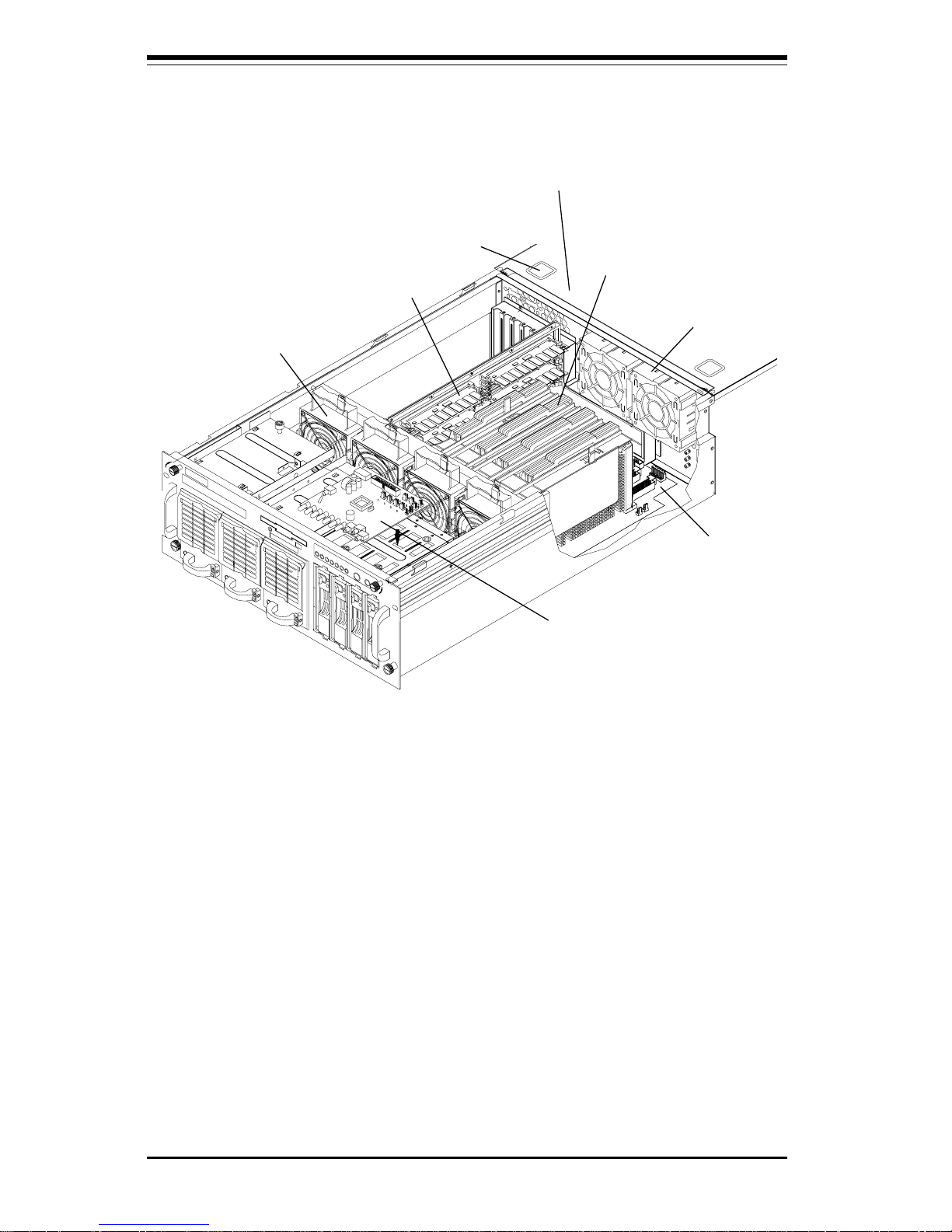
Figure 2-5. Accessing the Inside of the SuperServer 8060
(with air shroud removed and Control Panel PCB elevated)
Exhaust Fans
Control Panel
PCB
Processors
MEC Card
Cooling Fans
Top Chassis Cover (Removed)
S2QE6
Motherboard
Cover Recesses

Chapter 2: Server Installation
2-9
2-6 Checking the Drive Bay Setup
Next, you should check to make sure the peripheral drives and the SCA
drives and backplane have been properly installed and all connections have
been made.
1. Accessing the drive bays:
All drives can be accessed from the front of the server. For servicing
the CD-ROM and floppy drives, you will need to remove the top
chassis cover. The SCSI disk drives can be installed and removed
from the front of the chassis without removing the top chassis cover.
2. Installing a CD-ROM and floppy disk drives:
Refer to Section 6-4 if you need to reinstall a CD-ROM and/or floppy
disk drive to the system.
3. Check the SCSI disk drives:
Depending upon your system's configuration, your system may have
some SCSI drives already installed. If you need to install SCSI drives,
please refer to Section 6-4.
4. Check the airflow:
Airflow is provided by four hot-swap input fans and two exhaust fans,
all of which are 9-cm in size. An air shroud has been installed to
direct sufficient cooling air to the processors, which generate the most
heat. Also note that all power and data cables have been routed in
such a way that they do not block the airflow generated by the fans.
5. Supplying power to the system:
The last thing you must do is supply power to the system. Plug all
three power cords from the three power supply units into a highquality power strip that offers protection from electrical noise and
power surges. It is recommended that you use an uninterruptible
power supply (UPS).

2-10
SUPERSERVER 8060 Manual
Notes
Chapter 3: System Interface
3-1
Chapter 3
System Interface
3-1 Overview
There are several LEDs on the control panel as well as others on the power
supply units, the SCSI drive carriers and the motherboard to keep you constantly informed of the overall status of the system as well as the activity
and health of specific components. There are also three switches that
allow you to take action based on the information provided by these LEDs.
This chapter explains the meanings of all LED indicators and audible alarms
and the appropriate response you may need to take.
3-2 Control Panel Switches
There are three push-button switches located on the front of the chassis.
These are (in order from left to right) a power on/off switch, an alarm
disable switch and a reset switch.
l POWER: This is the main power switch, which is used to apply or
turn off the power supplied to the power supply units on the 8060.
l ALARM: Depressing the alarm switch will disable the audible alarm,
which is generated to notify you of chassis overheating or a fan/power
supply failure. The LED indicating the cause of the alarm will remain illuminated after the audible alarm is disabled.
l RESET: The reset switch reboots the system.
ALARM
RESET

SUPERSERVER 8060 Manual
3-2
3-3 Control Panel LEDs
The control panel located on the front of the SC860 chassis has seven
LEDs. These LEDs provide you with critical information related to different
parts of the system. This section explains what each LED indicates when
illuminated and any corrective action you may need to take.
l Power: Indicates power is being supplied to the system's power
supply units. This LED should normally be illuminated when the system is
operating.
l NIC: Indicates network activity on the system when flashing.
l HDD: Indicates IDE channel activity. On the SuperServer 8060, this
light indicates CD-ROM drive activity when flashing.
l PWR Fault: Indicates a power supply failure. This should be ac-
companied by an audible alarm, which you can disable with the alarm
switch on the control panel. Inspect the power supply units at the front left
of the chassis. The unit with the red LED illuminated has failed. Refer to
Section 6-5 for instructions on replacing the failed unit. Because the power
Chapter 3: System Interface
3-3
supplies are hot-plug units, you do not need to remove power from the
system when replacing. (The third power supply unit is a backup that
activates automatically to keep power supplied to the system.)
l Fan Fail: Indicates a system fan failure. This may be one or more of
the four hot-swap intake fans or the two exhaust fans. A fan failure is
accompanied by an audible alarm, which you can disable with the alarm
switch on the control panel. When a fan stops working, all the other system fans will increase their RPM to compensate until the failed unit is replaced. (See Section 6-2 for more details.) Refer to Section 6-3 for instructions on replacing system fans. It is unnecessary to power down the
system as these are hot-swap fans. Note: You must use the exact same
brand and rating of fan for replacement. These can be obtained directly
from Supermicro.
l Overheat: Indicates an overheat condition in the chassis. This may
be caused by cables obstructing the airflow in the system, or the ambient
room temperature being too warm. You should also check to make sure
that the chassis cover is installed and that all fans are present and operating normally.
l SCA Channel: Indicates an overheat condition in the area of the
SCA SCSI drives and backplane. This may be caused by cables obstructing
the airflow in the system, or the ambient room temperature being too warm.
You should also check to make sure that the chassis cover is installed and
that all fans are present and operating normally.

SUPERSERVER 8060 Manual
3-4
3-4 SCSI Drive Carrier LEDs
Each SCSI drive carrier has two LEDs.
l Green: When illuminated, the green LED on the front of the SCSI drive
carrier indicates drive activity. A connection to the SCSI SCA backplane
enables this LED to blink on and off when that particular drive is being
accessed.
l Red: When illuminated, the red LED on the front of the SCSI drive
carrier indicates the drive has experienced a fault or has crashed. Please
refer to Section 6-4 for instructions on replacing failed SCSI drives.
3-5 Power Supply LEDs
Each of the three separate power units that comprise the power supply has
a single LED that can be illuminated either as green or red.
l Green: When green, the power unit has power applied to it and is
operating normally.
l Red: A red LED is normal only when system power has been turned
off. If the LED is red, it indicates that either (1) no power is being applied
to that particular power unit or (2) that particular power unit has failed.
First check to make sure the power cord for that unit is plugged into both
the power unit and a grounded wall outlet/power strip. If the power cord is
properly connected, not, refer to Section 6-5 for instructions on replacing
the power supply unit.
3-6 Motherboard LED
There is only one LED on the motherboard. When illuminated, it indicates
that system power is present on the motherboard. This LED is located at
the lower right hand corner of the S2QE6 when installed in and viewed
from the front of the rackmount chassis. This LED provides the same
indication as the Power LED on the control panel.
 Loading...