

Supermicro 8050 User Manual
®
SUPERSERVER 8050
USER’S MANUAL
1.0
SUPER

The information in this User’s Manual has been carefully reviewed and is believed to be
accurate. The vendor assumes no responsibility for any inaccuracies that may be
contained in this document, makes no commitment to update or to keep current the
information in this manual, or to notify any person or organization of the updates.
Please
Note: For the most up-to-date version of this manual, please see our
web site at www.supermicro.com.
SUPERMICRO COMPUTER reserves the right to make changes to the product described in
this manual at any time and without notice. This product, including software, if any, and
documentation may not, in whole or in part, be copied, photocopied, reproduced, translated
or reduced to any medium or machine without prior written consent.
IN NO EVENT WILL SUPERMICRO COMPUTER BE LIABLE FOR DIRECT, INDIRECT,
SPECIAL, INCIDENTAL, SPECULATIVE OR CONSEQUENTIAL DAMAGES ARISING FROM
THE USE OR INABILITY TO USE THIS PRODUCT OR DOCUMENTATION, EVEN IF
ADVISED OF THE POSSIBILITY OF SUCH DAMAGES. IN PARTICULAR, THE VENDOR
SHALL NOT HAVE LIABILITY FOR ANY HARDWARE, SOFTWARE, OR DATA STORED
OR USED WITH THE PRODUCT, INCLUDING THE COSTS OF REPAIRING, REPLACING,
INTEGRATING, INSTALLING OR RECOVERING SUCH HARDWARE, SOFTWARE, OR
DATA.
Any disputes arising between manufacturer and customer shall be governed by the laws of
Santa Clara County in the State of California, USA. The State of California, County of
Santa Clara shall be the exclusive venue for the resolution of any such disputes.
Supermicro's total liability for all claims will not exceed the price paid for the hardware
product.
Unless you request and receive written permission from SUPER MICRO COMPUTER, you
may not copy any part of this document.
Information in this document is subject to change without notice. Other products and
companies referred to herein are trademarks or registered trademarks of their respective
companies or mark holders.
Copyright © 2000 by SUPER MICRO COMPUTER INC.
All rights reserved.
Printed in the United States of America.

Preface
About This Manual
This manual is written for professional system integrators and PC technicians. It provides information for the installation and use of the SuperServer 8050. Installation and maintainance should be performed by experienced technicians only.
The SuperServer 8050 is a high-end quad processor server based on the
SC850 server chassis and the S2QR6, a quad processor motherboard that
supports up to four Pentium III/II Xeon processors.
Manual Organization
Chapter 1 provides a checklist of the main components included with the
server system and describes the main features of the SUPER S2QR6
mainboard and the SC850-W chassis, which make up the SuperServer 8050.
Refer to Chapter 2 for Quick Setup information. You should follow the
procedures in this chapter the first time you setup and run the SuperServer
8050. If your server was ordered without processor and memory components, this chapter will refer you to the appropriate sections of the manual
for their installation.
See Chapter 3 for details on the system interface, which includes the
functions and information provided by the front control panel on the chassis
as well as other LEDs located throughout the system.
Chapter 4 gives a general overview of safety precautions that should be
followed when installing and servicing the SuperServer 8050.
Chapter 5 provides detailed information on the motherboard, including the
locations and functions of connections, headers, jumpers, DIP switches and
IRQs. Refer to this chapter when adding or removing processors or main
memory and when reconfiguring the motherboard.
Refer to Chapter 6 for detailed information on the server chassis. You
should follow the procedures given in this chapter when installing, removing or reconfiguring SCSI or peripheral drives and when replacing system
power supply units and cooling fans.
iii
Preface

Chapter 7 includes an introduction to BIOS and provides detailed information on running the CMOS Setup Utility.
Appendix A offers information on BIOS error beep codes and messages.
Appendix B provides post diagnostic error messages.
Appendix C lists the figures included in this manual.
Appendix D lists the system specifications.
SUPERSERVER 8050 Manual
iv
v
SuperServer 8050 User's Manual
Introduction
Chp1
Quick Setup System
Interface
System
Safety
Motherboard
Details
Chassis
Details
BIOS and
Setup Routine
Chp3Chp2
Chp5
Chp4
Chp6
Appendices
Overview
Chassis
Mainboard
Contact Info
Overview
Precautions
Setup
OS
Overview
Switches
Cntrl Pnl LEDs
SCSI LEDs
Pwr Sply LEDs
MB LEDs
Static Sensitive
MB Installation
Conn. Cables
CPU Installation
MEC Install.
PCI Cards
MB Layout
Connector Def.
DIP Switches
Jumper Settings
I/O Ports/IDE/
SCSI Conn.
IRQs
Static Sensitive
Control Panel
System Fans
Drive Bay Inst.
Power Supply
Chp7 App. A/B/C/D
Introduction
BIOS Features
Running Setup
Electrical Safety
General Safety
ESD Safety
BIOS Beep
Codes
Post Diag. Error
Messages
List of Figures
System Specs
Preface

SUPERSERVER 8050 Manual
vi
Table of Contents
Preface
About This Manual ...................................................................................................... iii
Manual Organization ................................................................................................... iii
Manual Organization (Flowchart)............................................................................ iv
Chapter 1: Introduction
1-1 Overview ......................................................................................................... 1-1
1-2 Server Chassis Features.............................................................................. 1-2
1-3 Mainboard Features ....................................................................................... 1-3
1-4 Contacting Supermicro ................................................................................ 1-22
Chapter 2: Quick Setup
2-1 Overview and Precautions ........................................................................... 2-1
2-2 Setting up the SuperServer 8050 ............................................................... 2-1
Checking the Motherboard Setup .......................................................... 2-1
Checking the Drive Bay Setup .............................................................. 2-2
2- 3 Installing the Operating System ................................................................... 2-3
Chapter 3: System Interface
3-1 Overview ......................................................................................................... 3-1
3-2 Switches.......................................................................................................... 3-1
Power ........................................................................................................ 3-1
Alarm .......................................................................................................... 3-1
Reset .......................................................................................................... 3-1
3- 3 Front Control Panel LEDs .............................................................................. 3-1
Power ........................................................................................................ 3-1
NIC .............................................................................................................. 3-1
HDD ............................................................................................................ 3-1
PWR Fault.................................................................................................. 3-2
Fan Fail...................................................................................................... 3-2
Overheat ................................................................................................... 3-2
SCA Channel A ........................................................................................ 3-2
SCA Channel B ........................................................................................ 3-2
3-4 SCSI Drive LEDs............................................................................................. 3-3
3-5 Power Supply LEDs ....................................................................................... 3-3
3- 6 Motherboard LED ............................................................................................ 3-3

Chapter 4: System Safety
4-1 Electrical Safety Precautions ........................................................................ 4-1
4-2 General Safety Precautions .......................................................................... 4-2
4-3 ESD Safety Precautions ................................................................................. 4 -3
Chapter 5: Advanced Motherboard Setup
5- 1 Handling the S2QR6 Motherboard ................................................................ 5-1
5- 2 Motherboard Installation ................................................................................. 5 -2
5-3 Connecting Cables .......................................................................................... 5 -3
Connecting Data Cables .......................................................................... 5 -4
Connecting Power Cables....................................................................... 5-4
Connecting the Front Control Panel ....................................................... 5 - 5
5- 4 Installing Processors and DRMs ................................................................... 5 - 6
5- 5 Installing Memory in the MEC ........................................................................ 5-8
5- 6 Adding PCI Cards .......................................................................................... 5-11
5-7 Connector Definitions ................................................................................... 5-14
Power Supply Connectors ................................................................... 5-14
Secondary Power Connector............................................................... 5-14
Power LED ............................................................................................... 5-14
Fan Fail LED............................................................................................ 5-14
IDE LED ..................................................................................................... 5-15
Power Fail LED ...................................................................................... 5- 15
PWR_ON .................................................................................................. 5-15
NIC_LED ................................................................................................... 5-15
Reset ........................................................................................................ 5-16
Chassis Intrusion ................................................................................... 5-16
Keyboard Lock ....................................................................................... 5-16
Extra Universal Serial Bus Connection .............................................. 5-17
Overheat LED ......................................................................................... 5- 17
Speaker ................................................................................................... 5- 17
Alarm Reset ............................................................................................ 5-18
Fan Headers ........................................................................................... 5-18
Serial Ports ............................................................................................. 5-18
ATX PS/2 Keyboard and Mouse Ports ................................................ 5-19
Universal Serial Bus Connector .......................................................... 5- 19
Ethernet Port........................................................................................... 5-19
Wake-On-Ring ........................................................................................ 5-19
PWR P Header........................................................................................ 5-20
vii
Table of Contents

SUPERSERVER 8050 Manual
viii
5- 8 DIP Switch Settings ...................................................................................... 5-20
DIP Switch 1: Core/Bus Ratio .............................................................. 5-20
DIP Switch 2 ............................................................................................ 5-20
5- 9 Jumper Settings ............................................................................................. 5-21
Explanation of Jumpers ......................................................................... 5-21
Front Side Bus Speed ........................................................................... 5-21
Extra Chassis Intrusion Header ..........................................................5-21
Power Supply Fail Alarm Enable/Disable ............................................ 5-22
Overheat Buzzer Alarm Enable/Disable ............................................. 5-22
BIOS Select .............................................................................................. 5-22
Onboard LAN/NIC Enable/Disable......................................................... 5-23
LVD Channel A SCSI Termination Enable/Disable............................. 5-23
LVD Channel B SCSI Termination Enable/Disable ............................. 5-23
50-pin Legacy Channel B SCSI Termination Enable/Disable ........... 5-23
SCSI Enable/Disable................................................................................ 5-24
5-10 Port/Control Panel Connector Locations .................................................... 5-24
5-11 Parallel Port, Floppy/HDD and SCSI Connections .................................... 5-25
Parallel Port Connector ......................................................................... 5- 25
Floppy Connector ................................................................................... 5-25
IDE Connectors ...................................................................................... 5- 26
50-pin Legacy SCSI Connector ............................................................5-26
Ultra160 SCSI Connectors ..................................................................... 5-27
5-12 IRQs ................................................................................................................. 5-28
Chapter 6: Advanced Chassis Setup
6-1 Static-Sensitive Devices ................................................................................ 6-1
6- 2 Front Control Panel ......................................................................................... 6-3
6- 3 System Cooling Fans ...................................................................................... 6- 5
6-4 Drive Bay Installation ...................................................................................... 6 - 6
SCSI Drives ............................................................................................... 6-6
SCSI Backplane Jumper Settings .......................................................... 6-9
IDE and Floppy Drives .......................................................................... 6-11
6-5 Power Supply Units ...................................................................................... 6-12
Chapter 7: BIOS
7- 1 Introduction....................................................................................................... 7 -1
7- 2 BIOS Features.................................................................................................. 7-2
7- 3 Running Setup.................................................................................................. 7-2
Standard CMOS Setup ............................................................................. 7 -4
Advanced CMOS Setup ........................................................................... 7 -5

Table of Contents
Advanced Chipset Setup ........................................................................ 7-9
Power Management ................................................................................ 7-11
PCI/Plug and Play Setup ........................................................................ 7-14
Peripheral Setup...................................................................................... 7-17
Auto-Detect Hard Disks ........................................................................ 7-19
Change User/Supervisor Password.................................................... 7-19
Change Language Setting ..................................................................... 7-20
Auto Configuration with Optimal Settings .......................................... 7-20
Auto Configuration with Fail Safe Settings ....................................... 7-20
Save Settings and Exit .......................................................................... 7-20
Exit Without Saving ................................................................................. 7-21
Appendices:
Appendix A: BIOS Error Beep Codes and Messages ....................................... A - 1
Appendix B: AMIBIOS Post Diagnostic Error Messages ....................................B -1
Appendix C: List of Figures .................................................................................... C-1
Appendix D: System Specifications ...................................................................... D-1
ix

Notes
SUPERSERVER 8050 User's Manual
x

Chapter 1
Introduction to the SuperServer 8050
1-1 Overview
The Supermicro SuperServer 8050 is a high-end quad processor server
that utilizes the best technology currently available. The SuperServer 8050
is comprised of two main subsystems: the SC850 high-end server chassis
and the S2QR6 quad Pentium III/II Xeon processor mainboard. Please refer
to our web site for information on operating systems that have been certified for use with the SuperServer 8050.
In addition to the mainboard and chassis, various hardware components
have been included with the SuperServer 8050. The letters in parentheses
indicate which subsystem that component is included with: SS = server, MB
= motherboard, CS = chassis.
l Up to four (4) Pentium III XeonTM processors* (SS)
l One (1) Memory Expansion Card (MEC) (MB)
l Memory modules for up to 16 GB main system memory* (SS)
l One (1) floppy ribbon cable for 3.5-inch floppy drives (MB)
l One (1) 1.44" floppy drive (SS)
l One (1) IDE ribbon cable (MB)
l One (1) I/O backpanel shield (MB)
l Two (2) CPU Dual Retention Modules (DRMs) with screws (MB)
l SCSI Accessories
Two (2) 68-pin Ultra160 SCSI cables w/o active termination for two
SCA SCSI backplanes (CS)
One (1) 50-pin Legacy SCSI cable (MB)
One (1) set of SCSI driver diskettes (MB)
One (1) SCSI manual (MB)
l Two (2) TMR-008 CPU terminator cards (MB)
Chapter 1: Introduction
1-1

SUPERSERVER 8050 Manual
1-2
1-2 Server Chassis Features
The SuperServer 8050 is a high-end, scaleable server platform designed
with today's most state-of-the-art features. The following is a general
outline of the main features of the SC850 server chassis.
System Power
A triple redundant power supply consisting of three 350W units provides
700W of continuous power with a 350W backup. If either working unit
fails, you will be notified by alarm and the backup unit will automatically
activate. These are hot-swap units that can be replaced without powering
down the system.
SCSI Subsystem
The SCSI subsystem supports up to 10 80-pin SCA Ultra160 SCSI hard
drives. (Any standard 1" drives are supported. SCA = Single Connection
Attachment.) These can be configured as 10 drives on a single channel or
5 drives on two channels. The SCSI drives are connected to two SAF-TE
compliant SCA backplanes that provide power, bus termination and configuration settings. The SCSI drives are also hot-swap units. A RAID controller
card can be used with the SCA backplanes to provide data security.
Note: The operating system you use must have RAID support to enable the
hot-swap capability of the SCSI drives.
Front Control Panel
The SuperServer 8050's detailed control panel provides comprehensive
system monitoring and control. LEDs indicate network activity, power supply failure, fan failure, fan status, SCSI drive activity and failure and SCA
backplane overheat conditions. The main power button, system reset button and an alarm reset switch to disable audible alarms are also included.
l Six (6) VRMs (Voltage Regulator Modules) (MB)
You should also have received a User's Manual and Supermicro diskettes,
which contains several drivers and utilities.
*
Type and number depends upon the configuration ordered.

1-3
Chapter 1: Introduction
I/O Backplane
The SC850 is an SWTX form factor chassis. The SWTX I/O back panel
provides nine motherboard expansion slots, two COM ports, a parallel port,
two USB ports, PS/2 mouse and keyboard ports and an Ethernet port.
Cooling System
The SC850 chassis has an innovative cooling design that includes 9-cm hotplug redundant system cooling fans and two airflow guides. All fans operate continuously. If one fails, an alarm is activated and the RPM of the
remaining fans increase to compensate and maintain sufficient airflow. Additional cooling for the SCSI drive bays is provided by two 12-cm exhaust
fans.
1-3 Mainboard Features
At the heart of the SuperServer 8050 lies the S2QR6, a quad processor
motherboard designed to provide maximum performance in a four-way system. Below are the main features of the S2QR6.
Processors
The S2QR6 supports Pentium III and II Xeon 100 MHz FSB processors in 1,
2, 3 and 4-way configurations. 400-700 MHz processors and future higher
speed processors with a 100 MHz FSB will also be supported. Please refer
to the support section of our web site for a complete listing of supported
processors (http://www.supermicro.com/TechSupport.htm).
Memory
The MEC (Memory Expansion Card) included with your S2QR6 has 16 DIMM
slots that can support up to 16 GB of registered DIMM with ECC. Module
sizes of 128MB, 256MB, 512MB and 1 GB may be used to populate the MEC.
Onboard SCSI
Onboard SCSI is provided with an Adaptec AIC-7899 SCSI chip, which supports dual channel, Ultra160 SCSI at a throughput of 160 MB/sec for each
channel. The S2QR6 provides three SCSI ports: two 68-pin LVD Ultra160

SUPERSERVER 8050 Manual
1-4
connectors and one 50-pin Legacy SCSI connector, which is shared with
channel B.
PCI Expansion Slots
The S2QR6 has a total of eight PCI expansion slots consisting of two 64-bit
66 MHz slots, four 64/32-bit 33 MHz slots and two 32-bit 33 MHz slots. All
together they provide an I/O bandwidth of 931 MB/sec.
Onboard Controllers/Ports
An onboard IDE controller supports up to four UDMA/33 hard drives or
ATAPI devices. The color-coded I/O ports include two COM ports, a parallel
port, two USB ports, PS/2 mouse and keyboard ports and a 10/100 MB
Ethernet port.
Other Features
Other onboard features that promote system health include eight onboard
voltage monitors, a chassis intrusion header, auto-switching voltage regulators, chassis and CPU overheat sensors, virus protection and BIOS rescue.

1-5
Chapter 1: Introduction
1-4 Contacting Supermicro
Headquarters
Address: Super Micro Computer, Inc.
2051 Junction Avenue
San Jose, CA 95131 U.S.A.
Tel: +1 (408) 895-2001
Fax: +1 (408) 895-2008
E-mail: marketing@supermicro.com (General Information)
support@supermicro.com (Technical Support)
Web site: www.supermicro.com
European Office
Address: Super Micro Computer B.V.
Het Sterrenbeeld 28, 5215 ML,
's-Hertogenbosch, The Netherlands
Tel: +31 (0) 73-6400390
Fax: +31 (0) 73-6416525
E-mail: sales@supermicro.nl
support@supermicro.nl (Technical Support)
rma@supermicro.nl (Customer Support)

SUPERSERVER 8050 Manual
1-6
Notes

Chapter 2: Quick Setup
2-1
Chapter 2
Quick Setup
2-1 Overview and Precautions
This chapter provides a quick setup checklist to get your SuperServer 8050
up and operating. Following these steps in the order given should enable
you to have the system operating within a minimum amount of time. This
quick setup assumes that your SuperServer 8050 system has come to you
with processors and memory preinstalled. If your system is not already
fully integrated with a motherboard, processors, system memory etc.,
please turn to the Chapter noted in each step for details on installing these
components and configuring the system.
2-2 Setting up the SuperServer 8050
You should inspect the box the SuperServer 8050 was shipped in and note
if it was damaged in any way. If the server itself shows damage you
should file a damage claim with the carrier who delivered it.
Decide on a suitable place for setting up and operating the SuperServer
8050. You will need to place it in a clean, dust-free area that is well ventilated. Avoid areas where heat, electrical noise and electromagnetic fields
are generated. You will also need it placed near a grounded power outlet.
Once the 8050 is placed in the appropriate location, slide the locking tabs on
each caster down to keep it stationary.
Checking the Motherboard Setup
Open the left side panel (when facing the front of the chassis) to make
sure the motherboard is properly installed and all connections have been
made.
1. Remove the left chassis side panel:
First, make sure the keylock for the side panels (located near the top
at the rear of the chassis) is unlocked. Then remove the four screws
that secure the back lip of the side panel to the rear of the chassis.
Grasp the handle at the rear of the panel and pull straight back about
1/2 inch, at which point the panel should hit a stop. Swing the top of

2-2
SUPERSERVER 8050 Manual
the panel out and completely lift it away from the chassis. When
reinstalling this panel, make sure the raised holes along the bottom of
the chassis fit into the long holes in the bottom lip of the side panel.
2. Check the CPU core/bus ratio:
You should first verify that the CPU core/bus ratio as set with DIP
switch 1 matches the speed of your installed processors. This DIP
switch is defaulted to 5.5, which corresponds to 550 MHz processors
running on a 100 MHz front side bus (FSB). If the setting is different
or if you are using processors of a different speed, you may need to
change this setting. See page 5-20 for setting the proper value with
DIP switch 1. If your system came without processors, refer to page
5-6 for processor installation instructions.
3. Check the MEC:
The Memory Expansion Card (MEC) should be already installed and
populated with DIMMs. Make sure the MEC is secure in its slot and
that the retention plate is screwed firmly to the chassis. For details on
populating the MEC, refer to page 5-8.
4. Install add-on cards:
Install any add-on cards that you want added to the system. See page
5-11 for details on installing add-on cards.
5. Check all cable connections and airflow:
Make sure all power and data cables are properly and firmly connected
and not blocking the airflow. See page 5-4 for details on cable
connections. Position the airflow guides to concentrate airflow to the
processors and their heatsinks.
Checking the Drive Bay Setup
Open the right side panel to make sure the SCA backplanes are properly
installed and all connections have been made.
1. Remove the right chassis side panel:
To access the drive bays, remove the right side panel (when facing
the front of the chassis) by following the same procedures described
on the previous page for removing the left side panel. You will also
have to open the front doors on the right side of the chassis to
access the front of the drive bays. These doors may be secured with
a keylock located just below the system LEDs.
2. Install a CDROM and floppy disk drives:
See page 6-10 if you need to add a CDROM and/or floppy disk drive to
the system.

Chapter 2: Quick Setup
2-3
3. Check the SCSI disk drives:
Depending upon your system's configuration, your system may have
some SCSI drives already installed. If you need to install SCSI drives
or wish to change the channel configuration, please refer to page 6-6.
The drives are defaulted to a dual channel (channels A and B)
configuration.
4. Check the airflow:
Because most of the excess cabling is kept on this side of the
chassis, you should check to make sure all cables have been routed in
such a way that they do not block the airflow generated by the fans.
5. Supply power to the system:
The last thing you must do is supply power to the system. Plug all
three power cords from the three power supplies into a high-quality
power strip that offers protection from electrical noise and surges.
2-3 Installing the Operating System
The SuperServer 8050 is normally shipped without an operating system
(OS) installed. This is the last thing you need to do to make the system
operational. The OS is normally installed with a CDROM. Refer to the
documentation that came with your operating system to install it in the SuperServer 8050.

2-4
SUPERSERVER 8050 Manual
Notes

Chapter 3: System Interface
3-1
Chapter 3
System Interface
3-1 Overview
There are several LEDs on the front control panel as well as others on the
power supply units, the SCSI drives and the motherboard to keep you constantly informed of the overall status of the system as well as the activity
and health of specific components. There are also three switches that
allow you to take action based on the information provided by these LEDs.
This chapter explains the meanings of all LED indicators and audible alarms
and the appropriate responses you may need to take.
3-2 Switches
The front control panel has three push-button switches: a power on/
off switch, an alarm disable switch and a reset switch. These are accessed by opening the top right door on the front of the chassis.
l POWER: This is the main power switch that will turn off the power
supply.
l ALARM: Depressing the alarm switch will disable the audible alarm
that is generated to notify you of chassis overheating or fan/power supply
failure. The LED indicating the cause of the alarm will remain illuminated
after the alarm is disabled.
l RESET: The reset switch reboots the system.
3-3 Front Control Panel LEDs
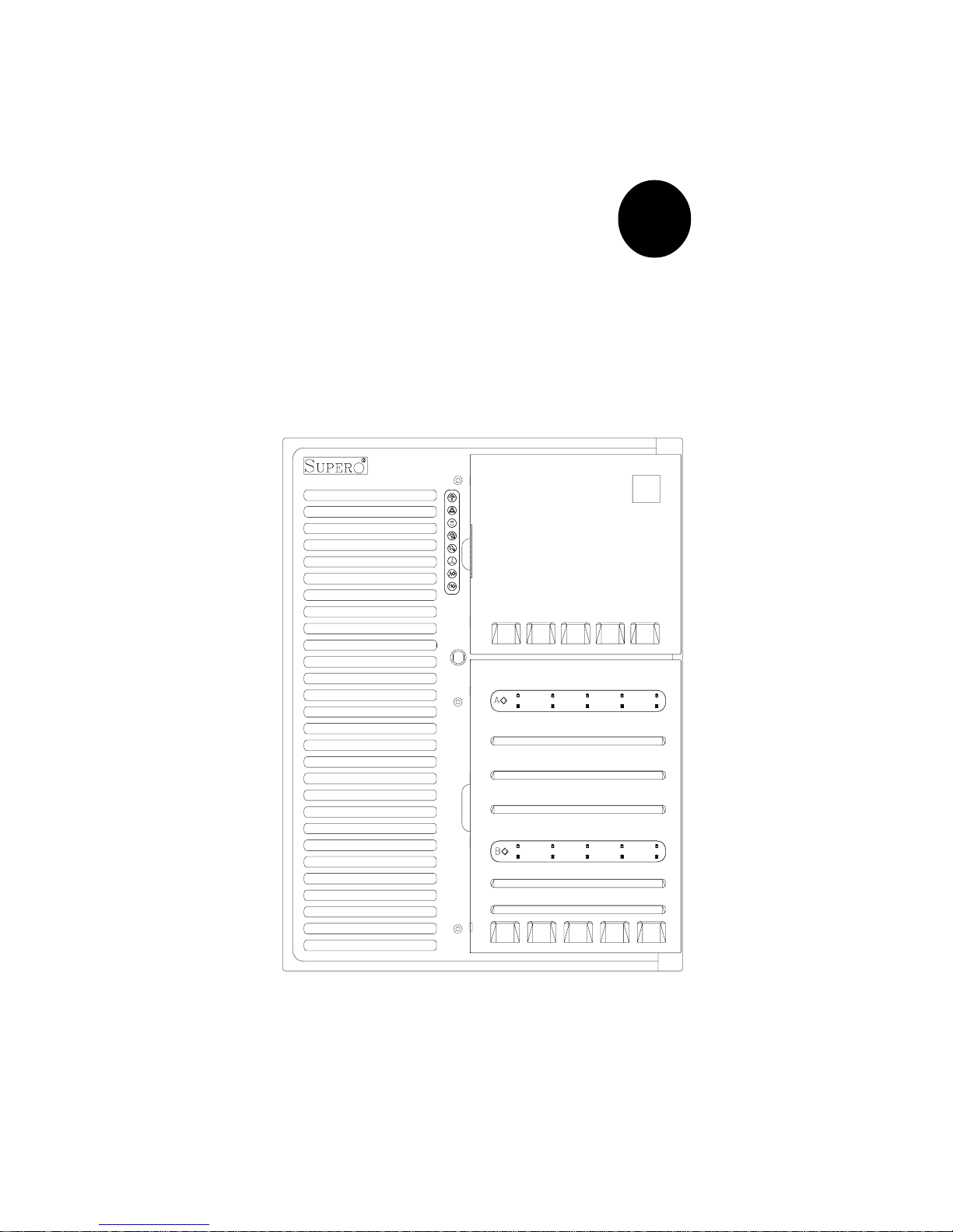
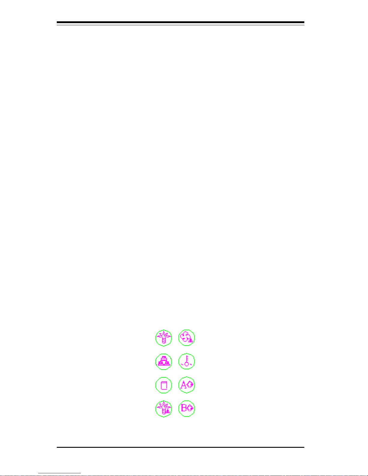
As shown in Figure 3-1, the front control panel of the SC850 chassis has
eight LEDs. These LEDs keep you informed of the status of your system
and indicate the following when illuminated.
l Power: Indicates power is being supplied to the system.
l NIC: Indicates network activity on the system.
l HDD: Indicates IDE drive activity.
SUPERSERVER 8050 Manual
3-2
l PWR Fault: Indicates a power supply failure. This should be accom-
panied by an audible alarm, which you can disable with the alarm switch on
the control panel. Inspect the power supply units at the rear of the chassis. The unit with the amber LED illuminated has failed. Refer to Chapter 6
for instructions on replacing the failed unit. Because they are hot-swap
units, you do not need to remove power from the system when replacing.
l Fan Fail: Indicates a system fan failure. This should be accompanied
by an audible alarm, which you can disable with the alarm switch on the
control panel. When a fan stops working, all the other system fans will
increase their RPM to compensate until the failed unit is replaced. Refer to
Chapter 6 for instructions on replacing system fans. It is unnecessary to
power down the system as these are hot-swap fans. Note: You must use
the exact same brand and rating of fan for replacement. These can be
obtained directly from Supermicro.
l Overheat: Indicates an overheat condition in the chassis.
l SCA Channel A: Indicates an overheat condition with SCA SCSI back
plane A (which supports the upper drive bays).
l SCA Channel B: Indicates an overheat condition with SCA SCSI back
plane B (which supports the lower drive bays).
Figure 3-1. Front Control Panel LEDs
Power
NIC
HDD
PWR Fault
Fan Fail
Overheat
SCA Channel A
SCA Channel B

Chapter 3: System Interface
3-3
3-4 SCSI Drive LEDs
Each SCSI drive carrier has two LEDs.
l Green: The green SCSI drive LED indicates drive activity. This LED
should blink on and off when that particular drive is being accessed.
l Red: If the red LED is illuminated, the drive has experienced a fault or
has crashed. Please refer to Chapter 6 for instructions on replacing failed
SCSI drives.
3-5 Power Supply LEDs
Each of the three units comprising the power supply has a single LED that
can be illuminated either as green or amber.
l Green: When green, the unit has power applied to it and is operating
normally.
l Amber: If the LED is amber, it indicates that no power is being applied
to that unit. If system power has been turned off this is normal, however if
the system is powered on and running an amber LED most likely indicates a
failed power unit. First check to make sure the power cord for that unit is
plugged in. If it is, then refer to Chapter 6 for instructions on replacing the
unit. The power unit's fan may continue to run at low speed even if the unit
has failed or has been turned off.
3-6 Motherboard LED
There is only one LED on the motherboard. When illuminated, it indicates
that system power is present on the motherboard. This LED is located just
below the PWR_SEC connector, which is at the top right corner of the
board when installed in the chassis. It provides the same indication as the
Power LED on the front control panel.

SUPERSERVER 8050 Manual
3-4
Notes
Chapter 4: System Safety
4-1
Chapter 4
System Safety
4-1 Electrical Safety Precautions
!
Basic electrical safety precautions should be followed to protect
yourself from harm and the SuperServer 8050 from damage:
l Be aware of the locations of the power on/off switch on the
chassis as well as the room's emergency power-off switch,
disconnection switch or electrical outlet. If an electrical accident
occurs, you can then quickly remove power from the system.
l Do not work alone when working with high voltage components.
l Power should always be disconnected from the system when
removing or installing main system components, such as the
motherboard, the MEC, memory modules and IDE and floppy drives.
When disconnecting power, you should first power down the
system with the operating system first and then unplug the power
cords of all the power supply units in the system.
l When working around exposed electrical circuits, another person
who is familiar with the power-off controls should be nearby to
switch off the power if necessary.
l Use only one hand when working with powered-on electrical
equipment. This is to avoid making a complete circuit, which will
cause electrical shock. Use extreme caution when using metal
tools, which can easily damage any electrical components or circuit
boards they come into contact with.
l Do not use mats designed to decrease static electrical discharge as
protection from electrical shock. Instead, use rubber mats that
have been designed as electrical insulators.
l The power supply power cords must include a grounding plug and
must be plugged into grounded electrical outlets.
SUPERSERVER 8050 Manual
4-2
4-2 General Safety Precautions
Follow these rules to ensure general safety:
l Keep the area around the SuperServer 8050 clean and free of
clutter.
l The SuperServer 8050 weighs approx. 84 lbs. (38 kg.) If you have
to lift the system, two people at either end should lift slowly with
their feet spread out to distribute the weight. Always keep your
back straight and lift with your legs.
l Place side panels and any system components that have been
removed away from the system so that they won't accidentally be
stepped on.
l While working on the system, do not wear loose clothing such as
neckties and unbuttoned shirt sleeves that can come into contact
with electrical circuitry or be pulled into the one of the cooling fans.
l Remove any jewelry or metal objects from your body, which are
excellent metal conductors that can create short circuits and harm
you if they come into contact with printed circuit boards or areas
where power is present.
l After servicing the system, reinstall all covers and side panels and
ensure all connections have been made.
!
l Motherboard Battery: CAUTION - There is a danger of explosion if
the onboard battery (located near the MEC and IDE#2 connectors) is
installed upside down, which will reverse its polarites. This battery
must be replaced only with the same or an equivalent type
recommended by the manufacturer. Dispose of used batteries
according to the manufacturer's instructions.

Chapter 4: System Safety
4-3
4-3 ESD Precautions
Electrostatic discharge (ESD) is generated by two objects with
different electrical charges coming into contact with each other. An
electrical discharge is created to neutralize this difference, which can
damage electronic components and printed circuit boards. The
following measures are generally sufficient to neutralize this
difference before contact is made to protect your equipment from ESD:
l Use a grounded wrist strap designed to prevent static discharge.
l Keep all components and printed circuit boards (PCBs) in their
antistatic bags until ready for use.
l Touch a grounded metal object before removing the board from the
antistatic bag.
l Do not let components or PCBs come into contact with your
clothing, which may retain a charge even if you are wearing a wrist
strap.
l Handle a board by its edges only; do not touch its components,
peripheral chips, memory modules or gold contacts.
l When handling chips or modules, avoid touching their pins.
l Put the motherboard and peripherals back into their antistatic bags
when not in use.
l For grounding purposes, make sure your computer chassis
provides excellent conductivity between the power supply, the case,
the mounting fasteners and the motherboard.
!

SUPERSERVER 8050 Manual
4-4
Notes

Chapter 5: Advanced Motherboard Setup
5-1
Chapter 5
Advanced Motherboard Setup
This chapter covers the steps required to install the S2QR6 motherboard
into a chassis, connect the data and power cables and install add-on cards.
All motherboard jumpers and connections are also described. A layout and
quick reference chart are on pages 5-12 and 5-13. Remember to remount
the side panel when you have finished with the installation to better cool
and protect the system.
Tools Required
The only tools you will need to install the S2QR6 into a chassis are a
long and a short Philips screwdriver.
5-1 Handling the S2QR6 Motherboard
Static electrical discharge can damage electronic components. To prevent
damage to any printed circuit boards (PCBs), it is important to handle them
very carefully. Also note that the size and weight of the S2QR6 motherboard can cause it to bend if handled improperly, which may result in damage. To prevent the S2QR6 motherboard from bending, keep one hand
under the center of the board to support it when handling. The following
measures are generally sufficient to protect your equipment from static
discharge.
Precautions
• Use a grounded wrist strap designed to prevent static discharge.
• Touch a grounded metal object before removing any board from its antistatic bag.
• Handle a board by its edges only; do not touch its components, peripheral chips, memory modules or gold contacts.
• When handling chips or modules, avoid touching their pins.
• Put the motherboard, add-on cards and peripherals back into their antistatic bags when not in use.

5-2
SUPERSERVER 8050 Manual
5-2 Motherboard Installation
This section explains the first step of physically mounting the S2QR6 into
the SC850 chassis. To remove the motherboard, follow the procedure in
reverse order. Following the steps in the order given will eliminate the most
common problems encountered in such an installation.
1. Removing the left chassis side panel:
The left side panel (when facing the chassis) must be removed to
access the motherboard side of the chassis. First, make sure the
keylock for the side panels (located at the top rear of the chassis) is
unlocked. Then remove the four screws that secure the lip of the
side panel to the back of the chassis. Grasp the handle at the rear
of the panel and pull straight back about 1/2 inch, at which point the
panel should hit a stop. Swing the top of the panel out and completely lift it away from the chassis. When reinstalling this panel,
make sure the raised holes along the bottom of the chassis fit into
the long holes in the bottom lip of the panel.
2. Installing metal standoffs and rubber feet:
With the side panel removed, the motherboard tray is directly in front
of you. First, check that the location of all the mounting holes on
both the motherboard and the tray match. Refer to Figure 5-1 for
mounting hole locations. Attach metal standoffs to the holes labeled
"Q" on the motherboard tray. Make sure these metal standoffs either
click in or are screwed in tightly. There are eight additional square
metal standoffs that are required for mounting the DRMs (Dual
Retention Modules), which should be preinstalled. Several square
rubber "feet" must be applied to the motherboard tray to function as
shock absorbers. Attach these feet to the small square outlines on
the tray.
• For grounding purposes, make sure your computer chassis provides excellent conductivity between the power supply, the case, the mounting
fasteners and the motherboard.
Unpacking
The motherboard is shipped in antistatic packaging to avoid static electrical
damage. When unpacking the board, make sure the person handling it is
static protected.
 Loading...