

Supermicro 8048B-TR4FT User Manual
USER'S MANUAL
Revision 1.0b
SuperServer
8048B-TR4FT

The information in this User’s Manual has been carefully reviewed and is believed to be accurate.
The vendor assumes no responsibility for any inaccuracies that may be contained in this document,
makes no commitment to update or to keep current the information in this manual, or to notify any
person or organization of the updates. Please Note: For the most up-to-date version of this
manual, please see our web site at
www.supermicro.com.
Super Micro Computer, Inc. ("Supermicro") reserves the right to make changes to the product
described in this manual at any time and without notice. This product, including software and
documentation, is the property of Supermicro and/or its licensors, and is supplied only under a
license. Any use or reproduction of this product is not allowed, except as expressly permitted by
the terms of said license.
IN NO EVENT WILL SUPERMICRO BE LIABLE FOR DIRECT, INDIRECT, SPECIAL, INCIDENTAL,
SPECULATIVE OR CONSEQUENTIAL DAMAGES ARISING FROM THE USE OR INABILITY TO
USE THIS PRODUCT OR DOCUMENTATION, EVEN IF ADVISED OF THE POSSIBILITY OF
SUCH DAMAGES. IN PARTICULAR, SUPERMICRO SHALL NOT HAVE LIABILITY FOR ANY
HARDWARE, SOFTW ARE, OR DA TA ST ORED OR USED WITH THE PRODUCT, INCLUDING THE
COSTS OF REPAIRING, REPLACING, INTEGRATING, INSTALLING OR RECOVERING SUCH
HARDWARE, SOFTWARE, OR DATA.
Any disputes arising between manufacturer and customer shall be governed by the laws of Santa
Clara County in the State of California, USA. The State of California, County of Santa Clara shall
be the exclusive venue for the resolution of any such disputes. Super Micro's total liability for all
claims will not exceed the price paid for the hardware product.
FCC Statement: This equipment has been tested and found to comply with the limits for a Class
A digital device pursuant to Part 15 of the FCC Rules. These limits are designed to provide
reasonable protection against harmful interference when the equipment is operated in a commercial
environment. This equipment generates, uses, and can radiate radio frequency energy and, if not
installed and used in accordance with the manufacturer’s instruction manual, may cause harmful
interference with radio communications. Operation of this equipment in a residential area is likely
to cause harmful interference, in which case you will be required to correct the interference at your
own expense.
California Best Management Practices Regulations for Perchlorate Materials: This Perchlorate
warning applies only to products containing CR (Manganese Dioxide) Lithium coin cells. “Perchlorate
Material-special handling may apply. See
www.dtsc.ca.gov/hazardouswaste/perchlorate”
WARNING: Handling of lead solder materials used in this
product may expose you to lead, a chemical known to
the State of California to cause birth defects and other
reproductive harm.
Manual Revision 1.0b
Release Date: June 27, 2016
Unless you request and receive written permission from Super Micro Computer, Inc., you may not
copy any part of this document.
Information in this document is subject to change without notice. Other products and companies
referred to herein are trademarks or registered trademarks of their respective companies or mark
holders.
Copyright © 2016 by Super Micro Computer, Inc.
All rights reserved.
Printed in the United States of America

iii
Preface
Preface
About This Manual
This manual is written for professional system integrators and PC technicians. It
provides information for the installation and use of the SuperServer 8048B-TR4FT.
Installation and maintenance should be performed by experienced technicians only .
The SuperServer 8048B-TR4FT is a high-end server based on the
SC848XTS-R3240BP 4U rackmount chassis and the quad processor X10QBi
serverboard, the X10QBi-MEM2 memory module card and the AOM-X10QBi-A
I/O card.
Manual Organization
Chapter 1: Introduction
The fi rst chapter provides a checklist of the main components included with the
server system and describes the main features of the X10QBi serverboard and the
SC848XTS-R3240BP chassis.
Chapter 2: Server Installation
This chapter describes the steps necessary to install the SuperServer 8048B-TR4FT
into a rack and check out the server confi guration prior to powering up the system.
If your server was ordered without processor and memory components, this chapter
will refer you to the appropriate sections of the manual for their installation.
Chapter 3: System Interface
Refer here for details on the system interface, which includes the functions and
information provided by the control panel on the chassis as well as other LEDs
located throughout the system.
Chapter 4: Standardized Warning Statements
You should thoroughly familiarize yourself with this chapter for a general overview
of safety precautions that should be followed when installing and servicing the
SuperServer 8048B-TR4FT.
Chapter 5: Advanced Serverboard Setup
Chapter 5 provides detailed information on the X10QBi serverboard, including the
locations and functions of connections, headers and jumpers. Refer to this chapter
when adding or removing processors or main memory and when reconfi guring the
serverboard.

SUPERSERVER 8048B-TR4FT USER'S MANUAL
iv
Chapter 6: Advanced Chassis Setup
Refer to Chapter 6 for detailed information on the SC848XTS-R3240BP server
chassis. You should follow the procedures given in this chapter when installing,
removing or reconfi guring SATA or peripheral drives and when replacing system
power supply units and cooling fans.
Chapter 7: BIOS
The BIOS chapter includes an introduction to BIOS and provides detailed information
on running the CMOS Setup Utility.
Appendix A: BIOS Error Beep Codes
Appendix B: System Specifi cations

v
Notes
Preface

vi
Table of Contents
Chapter 1 Introduction
1-1 Overview .........................................................................................................1-1
1-2 Serverboard Features .....................................................................................1-2
Processors ......................................................................................................1-2
Memory ...........................................................................................................1-2
Serial ATA .......................................................................................................1-2
PCI Expansion Slots ....................................................................................... 1-2
1-3 Server Chassis Features ................................................................................ 1-3
System Power .................................................................................................1-3
SATA Subsystem ............................................................................................. 1-3
Front Control Panel ......................................................................................... 1-3
I/O Ports ..........................................................................................................1-3
Cooling System ...............................................................................................1-3
Air Shrouds ..................................................................................................... 1-3
Mounting Rails ................................................................................................ 1-4
1-4 Memory Modules .............................................................................................1-4
1-5 I/O Card ...........................................................................................................1-4
1-6 Contacting Supermicro .................................................................................... 1-6
Chapter 2 Rack Installation
2-1 Overview .........................................................................................................2-1
2-2 Unpacking the System ....................................................................................2-1
2-3 Preparing for Setup ......................................................................................... 2-1
Choosing a Setup Location .............................................................................2-1
2-4 Warnings and Precautions .............................................................................. 2-2
Rack Precautions ............................................................................................2-2
General Server Precautions ............................................................................2-2
Rack Mounting Considerations .......................................................................2-2
Ambient Operating Temperature ................................................................ 2-2
Reduced Airfl ow ......................................................................................... 2-3
Mechanical Loading ................................................................................... 2-3
Circuit Overloading ..................................................................................... 2-3
Reliable Ground ......................................................................................... 2-3
2-5 Rack Mounting Instructions .............................................................................2-4
Identifying the Inner Rack Rails ...................................................................... 2-4
Installing the Inner Rails on the Chassis ........................................................2-5
Installing the Outer Rails onto a Rack ............................................................ 2-6
SUPERSERVER 8048B-TR4FT USER'S MANUAL

vii
Installing the Chassis into a Rack...................................................................2-8
Removing the Chassis from the Rack ............................................................ 2-9
Chapter 3 System Interface
3-1 Overview .........................................................................................................3-1
3-2 Control Panel Buttons .....................................................................................3-2
Power ..............................................................................................................3-2
Reset ...............................................................................................................3-2
3-3 Control Panel LEDs ........................................................................................ 3-2
Power ..............................................................................................................3-2
HDD ................................................................................................................. 3-2
NIC1 ................................................................................................................3-3
NIC2 ................................................................................................................3-3
Universal Information LED ..............................................................................3-3
3-4 Drive Carrier LEDs .......................................................................................... 3-4
Chapter 4 Standardized Warning Statements for AC Systems
4-1 About Standardized Warning Statements ....................................................... 4-1
Warning Defi nition ........................................................................................... 4-1
Installation Instructions ....................................................................................4-4
Circuit Breaker ................................................................................................ 4-5
Power Disconnection Warning ........................................................................ 4-6
Equipment Installation ..................................................................................... 4-8
Restricted Area ................................................................................................ 4-9
Battery Handling ............................................................................................4-10
Redundant Power Supplies .......................................................................... 4-12
Backplane Voltage ........................................................................................ 4-13
Comply with Local and National Electrical Codes ........................................4-14
Product Disposal ...........................................................................................4-15
Hot Swap Fan Warning .................................................................................4-16
Power Cable and AC Adapter ...................................................................... 4-18
Chapter 5 Advanced Serverboard Setup
5-1 Handling the Serverboard ...............................................................................5-1
Precautions .....................................................................................................5-1
5-2 Connecting Cables .......................................................................................... 5-2
Connecting Data Cables .................................................................................5-2
5-3 Control Panel Connectors and I/O Ports ........................................................ 5-3
Connecting the Control Panel ......................................................................... 5-4
5-4 Processor and Heatsink Installation................................................................5-5
Installing a Passive CPU Heatsink ................................................................. 5-8
Table of Contents

viii
Removing the Heatsink ................................................................................... 5-9
Installing Memory ............................................................................................5-9
Memory Support ..............................................................................................5-9
Populating RDIMM/3DS LRDIMM (ECC) Memory Modules ....................5-12
5-6 I/O Module Board .......................................................................................... 5-13
5-7 Adding PCI Expansion Cards ....................................................................... 5-15
5-8 Baseboard Details ......................................................................................... 5-16
5-9 Connector Defi nitions .................................................................................... 5-18
5-10 Jumper Settings ............................................................................................5-25
Explanation of Jumpers ................................................................................ 5-25
5-11 Onboard Indicators ........................................................................................5-28
5-12 Serial ATA Ports ............................................................................................ 5-29
5-13 Installing Software .........................................................................................5-30
SuperDoctor® 5 ............................................................................................ 5-31
5-14 Onboard Battery ............................................................................................ 5-32
Chapter 6 Advanced Chassis Setup
6-1 Static-Sensitive Devices ..................................................................................6-1
Precautions .....................................................................................................6-1
6-2 Control Panel ..................................................................................................6-2
6-3 Installing Hard Drives ...................................................................................... 6-3
6-4 Accessing the Inside of the System................................................................6-5
Removing the Chassis Cover ......................................................................... 6-5
6-5 Installing the Air Shroud ..................................................................................6-6
Air Shrouds ..................................................................................................... 6-6
6-6 Cooling System ...............................................................................................6-7
6-7 Power Supply ................................................................................................. 6-9
Power Supply Replacement ............................................................................6-9
Chapter 7 BIOS
7-1 Introduction ......................................................................................................7-1
Starting BIOS Setup Utility ..............................................................................7-1
How To Change the Confi guration Data .........................................................7-1
Starting the Setup Utility ................................................................................. 7-2
7-2 Main Setup ......................................................................................................7-2
7-3 Advanced Setup Confi gurations...................................................................... 7-3
7-4 Event Logs .................................................................................................... 7-30
7-5 IPMI ............................................................................................................... 7-31
7-6 Secur it y ......................................................................................................... 7-33
7-7 Boot ............................................................................................................... 7-34
SUPERSERVER 8048B-TR4FT USER'S MANUAL

ix
Table of Contents
7-8 Save & Exit ................................................................................................... 7- 35
Appendix A BIOS Error Beep Codes
Appendix B System Specifi cations

SUPERSERVER 8048B-TR4FT USER'S MANUAL
x
Notes

Chapter 1
Introduction
1-1 Overview
The SuperServer 8048B-TR4FT is a high-end server comprised of four main
subsystems: the SC848XTS-R3240BP 4U server chassis and the X10QBi quad
processor serverboard (baseboard), eight X10QBi-MEM2 memory module cards
and one AOM-X10QBi-A I/O card. Please refer to our website for information on
operating systems that have been certifi ed for use with the system (www.supermicro.
com).
In addition to the serverboard and chassis, various hardware components have been
included with the SuperServer 8048B-TR4FT server, as listed below:
• Four passive heatsinks (SNK-P0048PS)
• One air shroud (MCP-310-41804-0B)
• Four 9-cm cooling fans (FAN-0146L4)
• Three 8-cm rear exhaust fans (FAN-0148L4)
• One SATA backplane (BPN-SAS-846A)
• Twenty-four hot-swap 3.5" HDD trays (MCP-220-00075-0B)
• One rail set (MCP-290-00057-0N)
Note: For your system to work properly, please follow the links below to download
all necessary drivers/utilities and the user’s manual for your server.
• Supermicro product manuals: http://www.supermicro.com/support/manuals/
• Product drivers and utilities: ftp://ftp.supermicro.com
• Product safety info: http://www.supermicro.com/about/policies/safety_
information.cfm
• If you have any questions, please contact our support team at:
support@supermicro.com
Chapter 1: Introduction
1-1

1-2
SUPERSERVER 8048B-TR4FT USER'S MANUAL
1-2 Serverboard Features
At the heart of the SuperServer 8048B-TR4FT lies the X10QBi, a quad processor
serverboard based on the Intel® C602J chipset and designed to provide maximum
performance. The X10QBi acts as a baseboard, into which an I/O card and memory
cards may be installed.
The sections below cover the main features of the X10QBi serverboard (see Figure
1-1 for a block diagram of the chipset).
Processors
The X10QBi supports four Intel® Xeon® E7-8800 v3/v4 or E7-4800 v3/v4 series
processors (Socket R1 LGA 2011). Please refer to the serverboard description
pages on our web site for a complete listing of supported processors (www.
supermicro.com).
Memory
The X10QBi uses eight memory cards that install into the eight memory slots on
the serverboard. Two cards are assigned to each CPU as follows: SMI slots P1M1/
P1M2 for CPU1, SMI slots P2M1/P2M2 for CPU2, SMI slots P3M1/P3M2 for CPU3
and SMI slots P4M1/P4M2 for CPU4.
Each memory card may be populated with up to 12 DIMMs (for a maximum
total of ninety-six (96)). With all cards fully populated, the system will
support up to a total of 12 TB of DDR4-1866/1600/1333/1066 MHz speed
1GB, 2GB, 4GB, 8GB, 16GB, 32GB or 64GB size ECC RDIMM/3DS LRDIMM
memory. See Chapter 5 for details.
Note: Check the Supermicro website (www.supermicro.com) for the latest memory
support information.
Serial ATA
A SATA controller is integrated into the Intel C602J chipset to provide two SATA
3.0 and four SATA 2.0 ports, which support RAID 0, 1, 5 and 10. The SATA drives
are hot-swappable units.
PCI Expansion Slots
The X10QBi serverboard has the following slots for expansion cards:
• Four (4) PCI Express 3.0 x16 slots
• Seven (7) PCI Express 3.0 x8 slots

Chapter 1: Introduction
1-3
1-3 Server Chassis Features
The following is a general outline of the main features of the SC848XTS server
chassis.
System Power
The SC848XTS chassis model includes four 1620 Watt power supplies consisting
of two active and two backup power modules. In the event your power supply fails,
replacement is simple and can be accomplished without tools.
SATA Subsystem
The SC848XTS supports up to twenty-four (24) 3.5" hot-swap hard drives. These
drives are connected to a backplane that provides power and control.
Front Control Panel
The SC848XTS chassis includes a control panel below the left handle of the chassis.
The control panel provides you with system monitoring and control. LEDs indicate
system power, HDD activity, network activity, an information LED and power supply
failure. A main power button and a system reset button are also included.
I/O Ports
The chassis provides eight full-height, full-length expansion card slots, a COM port,
two USB 2.0 ports and, on the I/O card, a VGA port, two 10 Gb Ethernet ports and
a dedicated IPMI Ethernet port.
Cooling System
Four 9-cm and three 8-cm system fans are powered from the chassis and controlled
via IPMI.
Air Shrouds
The SC848XTS chassis includes one mylar air shroud, which directs the airfl ow
where cooling is needed. Always use the air shroud included with your server.
Note: if four memory modules are installed, an additional air shroud must be used
(p/n MCP-310-41805-0B). See Chapter 6 for details.

1-4
SUPERSERVER 8048B-TR4FT USER'S MANUAL
Mounting Rails
The SC848XTS includes a set of quick-release rails, and can be placed in a rack
for secure storage and use. To setup your rack, follow the instructions described
in Chapter 2.
1-4 Memory Modules
The X10QBi-MEM2 memory boards plug directly into the X10QBi baseboard. The
memory boards feature a Jordan Creek C114 memory buffer chip. Each of these
buffer chips supports two channels (three DIMMs per channel). See Chapter 5 for
installation and details.
1-5 I/O Card
The AOM-X10QBi-A I/O card also is inserted directly into the X10QBi baseboard.
The I/O card includes an Intel X540 Ethernet controller and an ASP2400 BMC chip
to provide dual 10G based-T (RJ45) Ethernet ports and a dedicated IPMI port. This
chip also provides onboard video. See Chapter 5 for installation and details.
Chapter 1: Introduction
1-5
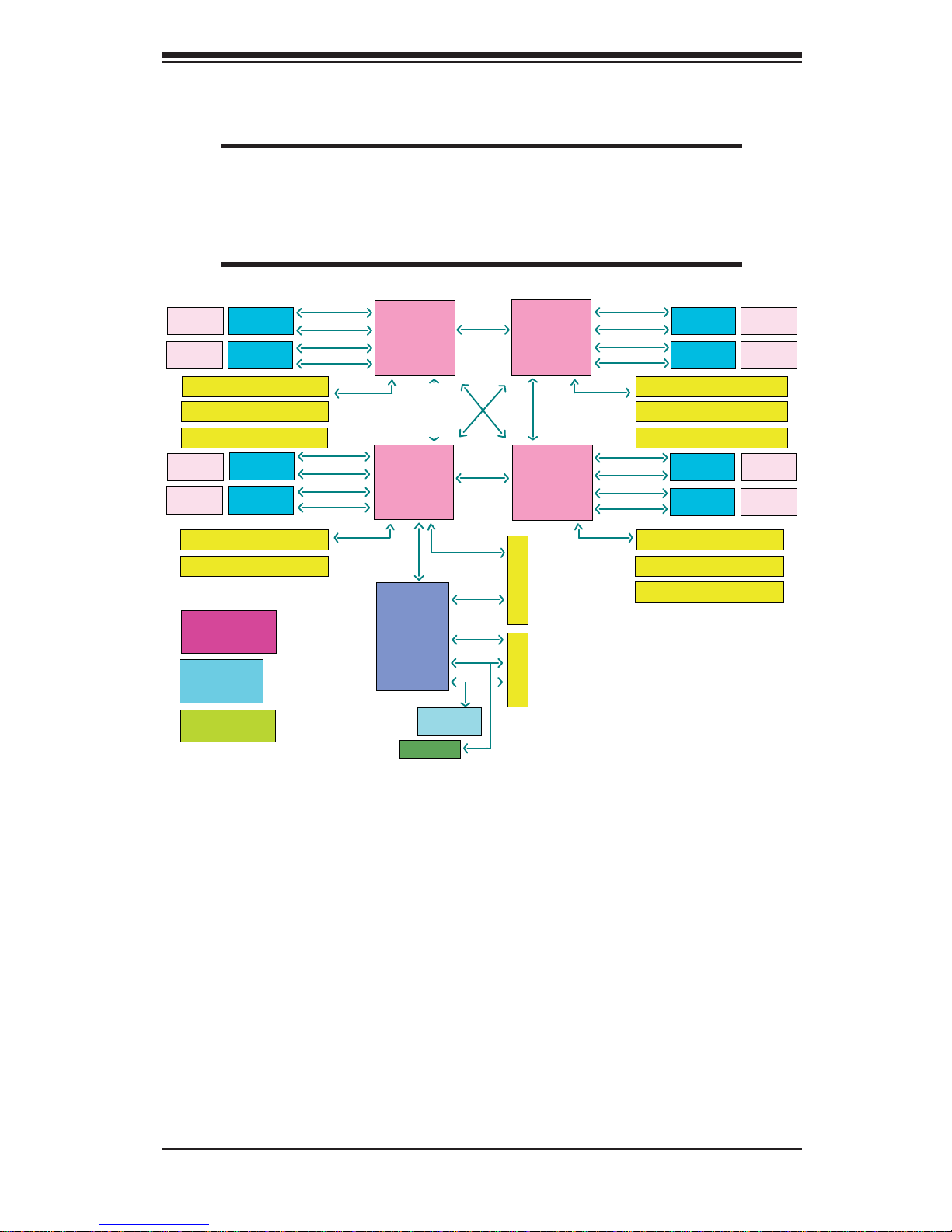
Figure 1-1. Intel Intel C602J Chipset:
System Block Diagram
Note: This is a general block diagram and may not exactly repre-
sent the features on your serverboard. See the previous pages for
the actual specifi cations of your serverboard. This block diagram is
intended for your reference only.
CPU3
CPU4
CPU2
CPU1
Intel
C602J
IO Slot/ x16 slot
IO Slot/ x8 slot
TPM Chip
HM
NCT7904D
CPU3_S1-PCIE G3x8 in X8slot
CPU3_S2-PCIE G3x8 in X8slot
CPU3_S3-PCIE G3x16 in X16slot
CPU2_S1-PCIE G3x8 in X8slot
CPU2_S2-PCIE G3x16 in X16slot
CPU2_S3-PCIE G3x8 in X8slot
CPU3_S2-PCIE G3x8 in X8slot
CPU3_S3-PCIE G3x16 in X16slot
CPU4_S1-PCIE G3x8 in X8slot
CPU4_S2-PCIE G3x8 in X8slot
CPU4_S3-PCIE G3x16 in X16slot
LPC
SMBus
USB
PCIE x1
X4 DMI2
PCIE-G3x32 LANEs
PCIE-G3x32 LANEs
PCIE-G3x32 LANEs
PCIE-G3x24
LANEs
PCIE-G3x8 LANEs
QPI 9.6 GT/s
QPI 9.6 GT/s
QPI 9.6 GT/s
QPI 9.6 GT/s
QPI 9.6 GT/s
SMI2 Slot
SMI2 Slot
SMI2 Slot
SMI2 Slot
SMI2 Slot
SMI2 Slot
SMI2 Slot
SMI2 Slot
Power
Connector
Power
Connector
Power
Connector
Power
Connector
Power
Connector
Power
Connector
Power
Connector
Power
Connector
SMI2-CH0-3.2GT/s
SMI2-CH1-3.2GT/s
SMI2-CH2-3.2GT/s
SMI2-CH3-3.2GT/s
SMI2-CH0-3.2GT/s
SMI2-CH1-3.2GT/s
SMI2-CH2-3.2GT/s
SMI2-CH3-3.2GT/s
SMI2-CH0-3.2GT/s
SMI2-CH1-3.2GT/s
SMI2-CH2-3.2GT/s
SMI2-CH3-3.2GT/s
SMI2-CH0-3.2GT/s
SMI2-CH1-3.2GT/s
SMI2-CH2-3.2GT/s
SMI2-CH3-3.2GT/s
XDP0: CPU1 & CPU4
CPU2 & CPU3
Clock Subsystem
Clock Gen
Clock Buffer
CPLD
Power Management
Reset & PowerGood

1-6
SUPERSERVER 8048B-TR4FT USER'S MANUAL
1-6 Contacting Supermicro
Headquarters
Address: Super Micro Computer, Inc.
980 Rock Ave.
San Jose, CA 95131 U.S.A.
Tel: +1 (408) 503-8000
Fax: +1 (408) 503-8008
Email: marketing@supermicro.com (General Information)
support@supermicro.com (Technical Support)
Website:
www.supermicro.com
Europe
Address: Super Micro Computer B.V.
Het Sterrenbeeld 28, 5215 ML
's-Hertogenbosch, The Netherlands
Tel: +31 (0) 73-6400390
Fax: +31 (0) 73-6416525
Email: sales@supermicro.nl (General Information)
support@supermicro.nl (Technical Support)
rma@supermicro.nl (Customer Support)
Website:
www.supermicro.nl
Asia-Pacifi c
Address: Super Micro Computer, Inc.
3F, No. 150, Jian 1st Rd.
Zhonghe Dist., New Taipei City 235
Taiwan (R.O.C)
Tel: +886-(2) 8226-3990
Fax: +886-(2) 8226-3992
Email: support@supermicro.com.tw
Website:
www.supermicro.com.tw

2-1
Chapter 2: Server Installation
Chapter 2
Rack Installation
2-1 Overview
This chapter provides a quick setup checklist to get your chassis up and running.
Following these steps in the order given should enable you to have the system
operational within a minimal amount of time.
2-2 Unpacking the System
You should inspect the box which the chassis was shipped in and note if it was
damaged in any way. If the chassis itself shows damage, you should fi le a damage
claim with the carrier who delivered it.
Decide on a suitable location for the rack unit that will hold your chassis. It should
be situated in a clean, dust-free area that is well ventilated. Avoid areas where
heat, electrical noise and electromagnetic fi elds are generated. The system needs
to be placed near a grounded power outlet. Be sure to read the Rack and Server
Precautions in the next section.
2-3 Preparing for Setup
The box your chassis was shipped in should include two sets of rail assemblies and
the mounting screws needed for installing the system into the rack. Also included
is an optional square hole to round hole converter bracket, for use in racks with
round mounting holes. Please read this section in its entirety before you begin the
installation procedure outlined in the sections that follow.
Choosing a Setup Location
• Leave enough clearance in front of the rack to enable you to open the front
door completely (~25 inches).
• Leave approximately 30 inches of clearance in the back of the rack to allow for
suffi cient airfl ow and ease in servicing.
• This product is for installation only in a Restricted Access Location (dedicated
equipment rooms, service closets and the like).

2-2
SUPERSERVER 8048B-TR4FT USER'S MANUAL
2-4 Warnings and Precautions
Rack Precautions
• Ensure that the leveling jacks on the bottom of the rack are fully extended to
the fl oor with the full weight of the rack resting on them.
• In single rack installations, stabilizers should be attached to the rack.
• In multiple rack installations, the racks should be coupled together.
• Always make sure that the rack is stable before extending a component from
the rack.
• You should extend only one component at a time - extending two or more
simultaneously may cause the rack to become unstable.
General Server Precautions
• Review the electrical and general safety precautions that came with the
components you are adding to your chassis.
• Determine the placement of each component in the rack before you install the
rails.
• Install the heaviest server components on the bottom of the rack fi rst, and then
work upwards.
• Use a regulating uninterruptible power supply (UPS) to protect the server from
power surges, voltage spikes and to keep your system operating in case of a
power failure.
• Allow the hot plug hard drives and power supply modules to cool before touching
them.
• Always keep the rack's front door and all panels and components on the servers
closed when not servicing to maintain proper cooling.
Rack Mounting Considerations
Ambient Operating Temperature
If installed in a closed or multi-unit rack assembly, the ambient operating
temperature of the rack environment may be greater than the ambient temperature
of the room. Therefore, consideration should be given to installing the equipment
in an environment compatible with the manufacturer’s maximum rated ambient
temperature (TMRA).
2-3
Chapter 2: Server Installation
Reduced Airfl ow
Equipment should be mounted into a rack so that the amount of airfl ow required
for safe operation is not compromised.
Mechanical Loading
Equipment should be mounted into a rack so that a hazardous condition does not
arise due to uneven mechanical loading.
Circuit Overloading
Consideration should be given to the connection of the equipment to the power
supply circuitry and the effect that any possible overloading of circuits might have
on overcurrent protection and power supply wiring. Appropriate consideration of
equipment nameplate ratings should be used when addressing this concern.
Reliable Ground
A reliable ground must be maintained at all times. To ensure this, the rack
itself should be grounded. Particular attention should be given to power supply
connections other than the direct connections to the branch circuit (i.e. the use of
power strips, etc.).
Warning! To prevent bodily injury when mounting or servicing this unit in a
rack, you must take special precautions to ensure that the system remains stable. The
following guidelines are provided to ensure your safety:
• This unit should be mounted at the bottom of the rack if it is the only unit in
the rack.
• When mounting this unit in a partially fi lled rack, load the rack from the bottom
to the top with the heaviest component at the bottom of the rack.
• If the rack is provided with stabilizing devices, install the stabilizers before
mounting or servicing the unit in the rack.

2-4
SUPERSERVER 8048B-TR4FT USER'S MANUAL
2-5 Rack Mounting Instructions
This section provides information on installing the SC848XTS chassis into a rack
unit with the rails provided. There are a variety of rack units on the market, which
may mean that the assembly procedure will differ slightly. You should also refer to
the installation instructions that came with the rack unit you are using.
Note: This rail will fi t a rack between 26.5” to 36.4" deep.
Identifying the Inner Rack Rails
The chassis package includes one pair of rack rail assemblies in the rack mounting
kit. Each assembly consists of an inner rail that secures to the chassis and an outer
rail that is attached directly to the rack.
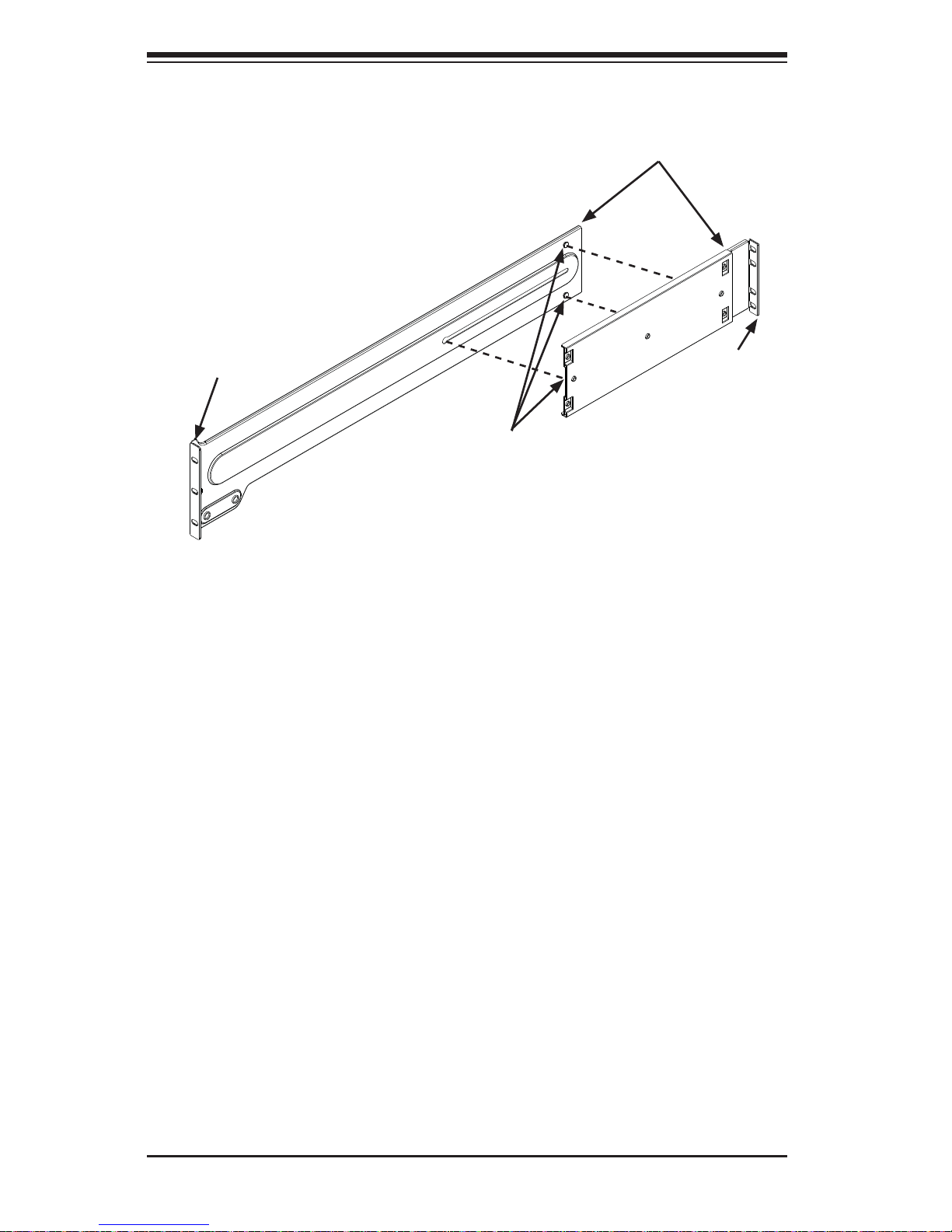
Figure 2-1. Installing the Inner Rails
Inner Rail Assembly
Warning: do not pick up the server by the front handles. They are designed
to pull the system from a rack only.
2-5
Chapter 2: Server Installation
Figure 2-2. Installing the Rails
Installing the Inner Rails on the Chassis
Installing the Inner Rails
1. The inner rails are etched with "L" (left side) and "R" (right side). Place one
inner rail on the side of the chassis, aligning the hooks of the chassis with the
inner rail holes. Make sure the rail faces "outward" so that it will fi t with the
rack's mounting bracket.
2. Slide the rail toward the front of the chassis to hook the inner rail onto the
side of the chassis.
3. Secure the chassis with two fl at head M4 x 4mm screws as illustrated.
4. Repeat steps 1-3 for the other inner rack rail.
1
1
1
2
1
3
2-6
SUPERSERVER 8048B-TR4FT USER'S MANUAL
Installing the Outer Rails onto a Rack
Installing the Outer Rails
1. Attach the short bracket to the outside of the long bracket. You must align the
pins with the slides. Also, both bracket ends must face the same direction.
2. Adjust both the short and long brackets to the proper distance so that the rail
fi ts snugly into the rack.
3. Secure the long bracket to the front side of the outer rail with two M5 screws
and washers and the short bracket to the rear side of the outer rail with three
M5 screws and washers. Keep the screws slack so that they may be adjusted
later.
4. Repeat steps 1-3 for the left outer rail.
Figure 2-3. Assembling the Outer Rails
Secure to the
Front of the Rack
Secure to the
Rear of the
Rack
Fixed Pins
Attach Outer
Rails Together
2-7
Chapter 2: Server Installation
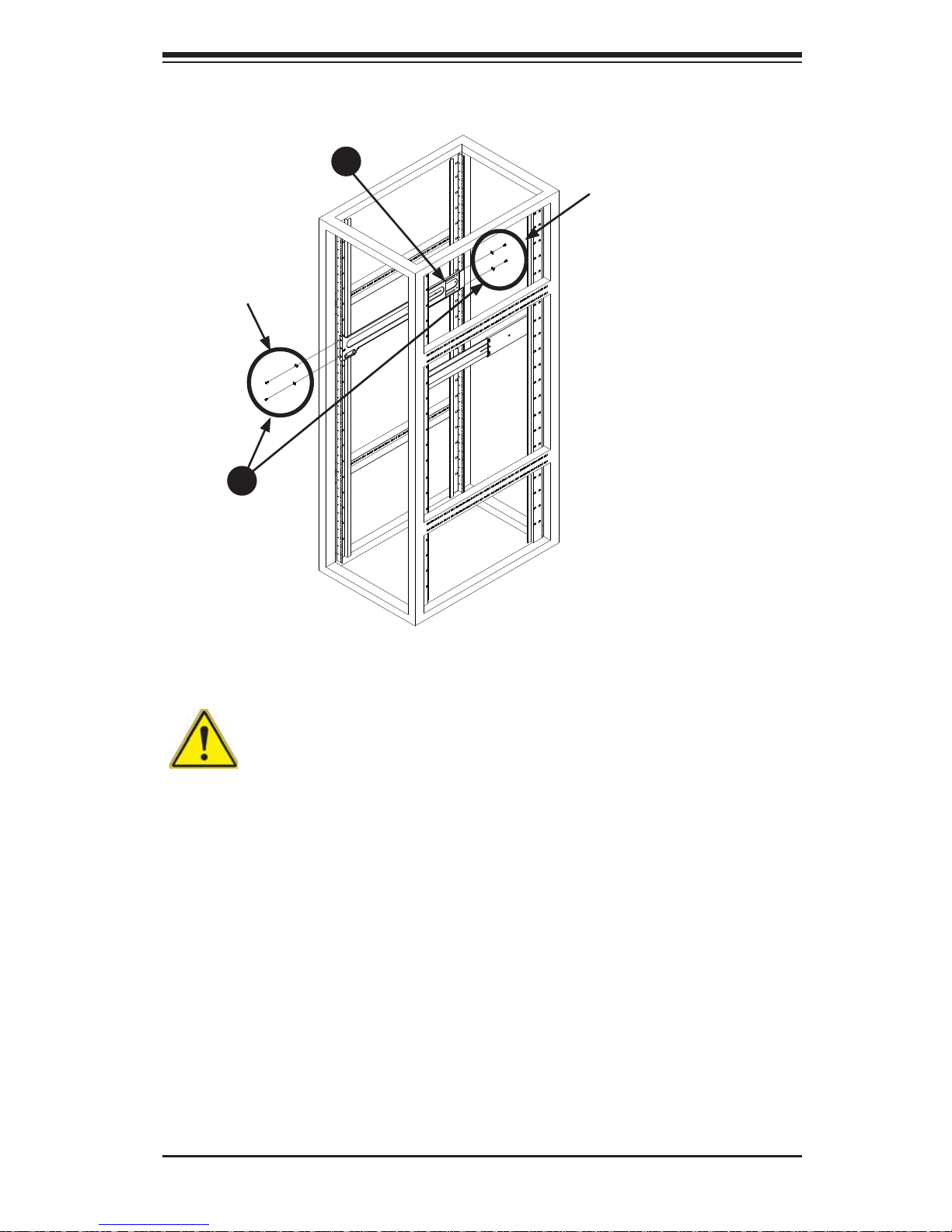
Figure 2-4. Installing the Outer Rails to the Rack
Screws and
Washers
Screws and
Washers
1
3
1
2
Note: fi gures are for illustrative purposes only. Always install servers into racks
from the bottom up.
Stability hazard. The rack stabilizing mechanism must be in place, or the
rack must be bolted to the fl oor before you slide the unit out for servicing. Failure to
stabilize the rack can cause the rack to tip over.
2-8
SUPERSERVER 8048B-TR4FT USER'S MANUAL
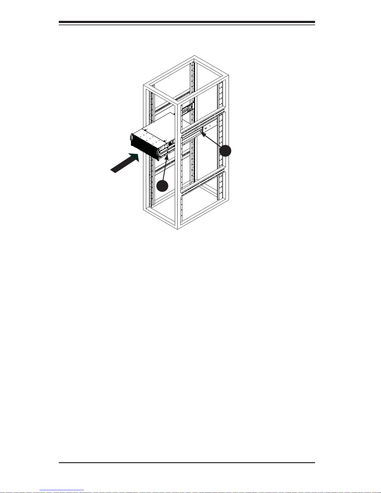
Figure 2-4. Installing the Chassis into a Rack
Installing the Chassis into a Rack
Installing the Chassis into a Rack:
1. Confi rm that chassis includes the inner rails (A) Also, confi rm that the outer
rails (B) are installed on the rack.
2. Line chassis rails (A) with the front of the rack rails (B).
3. Slide the chassis rails into the rack rails, keeping the pressure even on both
sides (you may have to depress the locking tabs when inserting). When the
server has been pushed completely into the rack, you should hear the locking
tabs "click" into the locked position.
4. Tighten up all the screws on the front side and rear side of both outer rails.
5. (Optional) Insert and tightening the thumbscrews that hold the front of the
server to the rack.
1
A
1
B
Note: fi gures are for illustrative purposes only. Always install servers into racks
from the bottom up.
2-9
Chapter 2: Server Installation
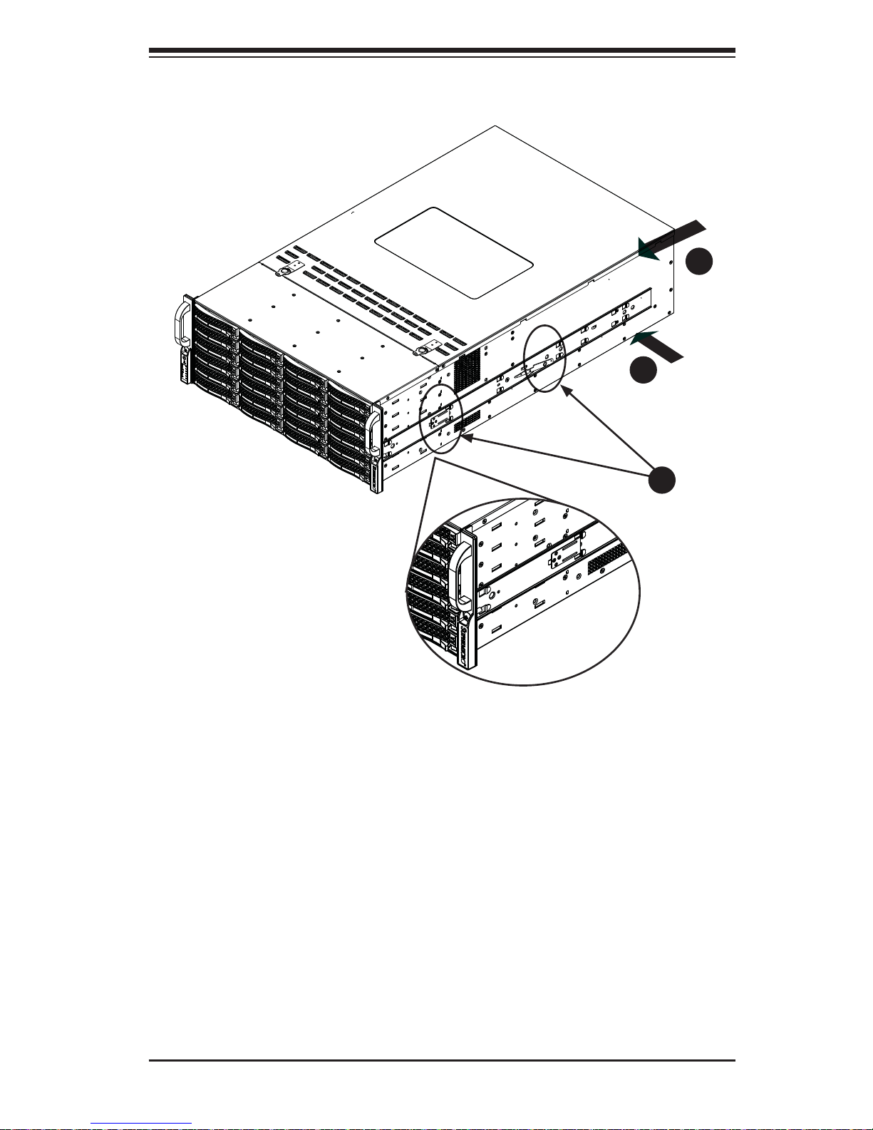
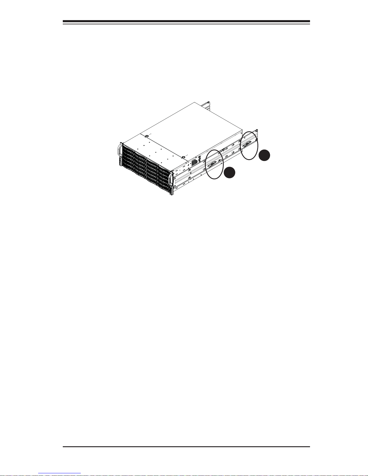
Figure 2-5. Removing the Chassis From the Rack
Removing the Chassis from the Rack
Caution! It may be dangerous for a single person to off-load the heavy chassis
from the rack without assistance. Be sure to have suffi cient assistance supporting
the chassis when removing it from the rack.
Removing the Chassis from the Rack
1. Pull the chassis forward out the front of the rack until it stops.
2. Press both of the black plastic release latches on each of the inner rails
downward simultaneously and move the chassis forward in the rack.
3. When the chassis stops a second time, press both of the black plastic release
latches on the rear of the inner rails downward simultaneously to fully remove
the chassis from the rack.
1
2
1
3

2-10
SUPERSERVER 8048B-TR4FT USER'S MANUAL
Notes
Chapter 3: System Interface
3-1
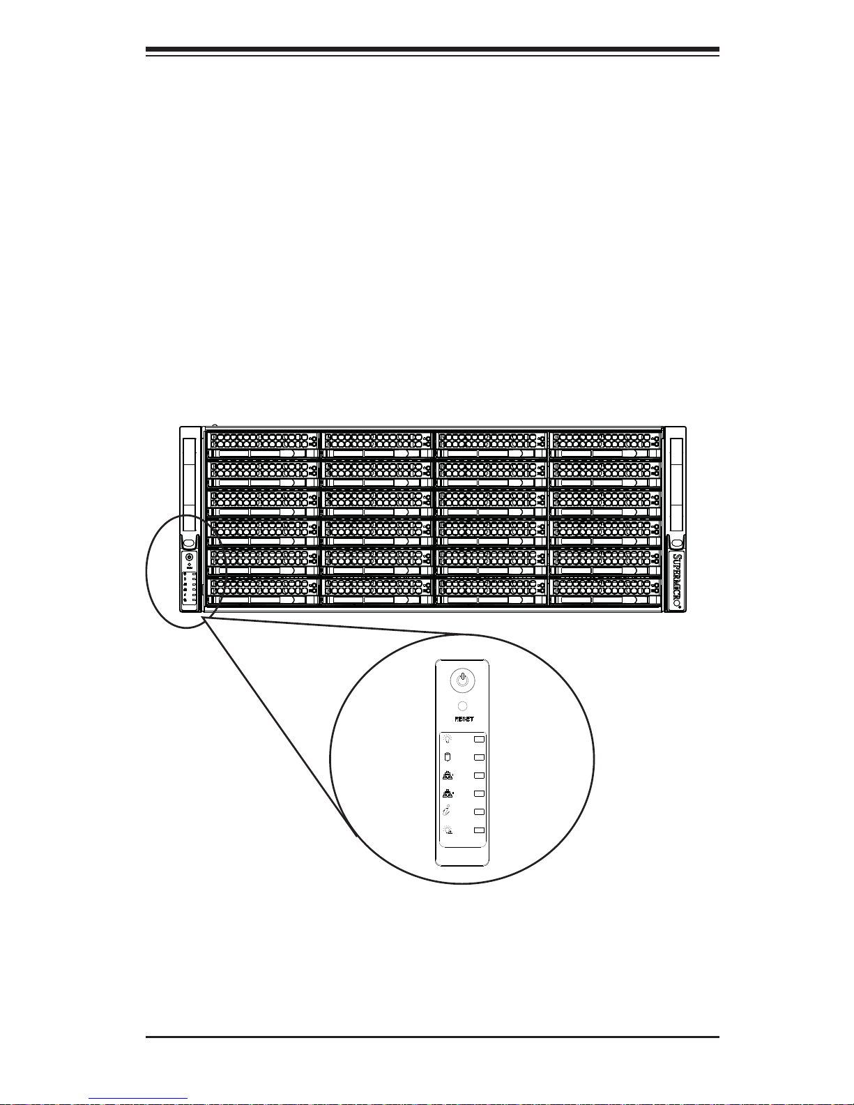
Figure 3-1. Front LED Panel
Chapter 3
System Interface
3-1 Overview
There are several LEDs on the control panel as well as others on the drive carriers
to keep you constantly informed of the overall status of the system as well as the
activity and health of specifi c components.
This chapter explains the meanings of all LED indicators and the appropriate
responses you may need to take.

3-2
SUPERSERVER 8048B-TR4FT USER'S MANUAL
3-2 Control Panel Buttons
There ar e two pu sh- butt ons inc luded on t he cont rol pan el: a power but ton an d a
reset button.
Power
Indicates power is being supplied to the system's power supply units. This LED
should normally be illuminated when the system is operating.
Power
The main power button is used to apply or remove power from the power supply
to the server system. Turning off system power with this button removes the main
power but keeps standby power supplied to the system, consequently you must
unplug the power cord before servicing the system.
Reset
The reset button is used to reboot the system.
3-3 Control Panel LEDs
The co ntro l pan el l oc ated o n th e lef t h and le of t he SC 8 4 8 ch ass is ha s fi ve LEDs.
These LE Ds provide you w ith cri tical inf ormatio n related to dif ferent p arts of t he
system. Thi s sec t io n expla ins w hat e ach L ED ind ic ate s whe n ill umi nated a nd any
corrective action you may need to take.
HDD
Indicates hard drive activity when fl ashing.
Chapter 3: System Interface
3-3
1
2
NIC1
Indicates network activity on GLAN1 when fl ashing.
NIC2
Indicates network activity on GLAN2 when fl ashing.
Universal Information LED
See the following table for the status shown by this LED.
Universal Information LED
Status Description
Continuously on and red An overheat condition has occurred. (This may be caused by cable congestion.)
Blinking red (1 Hz) Fan failure: check for an inoperative fan.
Blinking red (0.25 Hz) Power failure: check for an inoperative power supply.
Solid blue Local UID has been activated. Use this function to locate the server in a rack
environment.
Blinking blue (300 msec) Remote UID has been activated. Use this function to locate the server from a
remote location.
If the server overheats, you should check the following: Use the LEDs to determine
the nature of the overheating condition. Confi rm that the chassis covers are installed
properly. Check the routing of the cables and make sure all fans are present and
operating normally. Finally, verify that the heatsinks are installed properly.
3-4
SUPERSERVER 8048B-TR4FT USER'S MANUAL
3-4 Drive Carrier LEDs
The chassis includes externally accessible SAS/SATA drives. Each drive carrier
displays two status LEDs on the front of the carrier.
LED Color State Status
Activity LED
Green Solid On SAS drive installed
Green Blinking I/O activity
Status LED
Red Solid On Failed drive for SAS/SATA with RSTe
support
Red Blinking at 1 Hz Rebuild drive for SAS/SATA with RSTe
support
Red Blinking with two blinks
and one stop at 1 Hz
Hot spare for SAS/SATA with RSTe
support
Red On for fi ve seconds,
then off
Power on for SAS/SATA with RSTe
support
Red Blinking at 4 Hz Identify drive for SAS/SATA with RSTe
support
 Loading...