

SUPER
SUPERSERVER 8025C-3R
®
USER’S MANUAL
Revision 1.0a

The information in this User’s Manual has been carefully reviewed and is believed to be accurate.
The vendor assumes no responsibility for any inaccuracies that may be contained in this document,
makes no commitment to update or to keep current the information in this manual, or to notify any
person or organization of the updates. Please Note: For the most up-to-date version of this
manual, please see our web site at www.supermicro.com.
Super Micro Computer, Inc. ("Supermicro") reserves the right to make changes to the product
described in this manual at any time and without notice. This product, including software, if any,
and documentation may not, in whole or in part, be copied, photocopied, reproduced, translated or
reduced to any medium or machine without prior written consent.
IN NO EVENT WILL SUPERMICRO BE LIABLE FOR DIRECT, INDIRECT, SPECIAL, INCIDENTAL,
SPECULATIVE OR CONSEQUENTIAL DAMAGES ARISING FROM THE USE OR INABILITY TO
USE THIS PRODUCT OR DOCUMENTATION, EVEN IF ADVISED OF THE POSSIBILITY OF
SUCH DAMAGES. IN PARTICULAR, SUPERMICRO SHALL NOT HAVE LIABILITY FOR ANY
HARDWARE, SOFTW ARE, OR DA TA STORED OR USED WITH THE PRODUCT, INCLUDING THE
COSTS OF REPAIRING, REPLACING, INTEGRATING, INSTALLING OR RECOVERING SUCH
HARDWARE, SOFTWARE, OR DATA.
Any disputes arising between manufacturer and customer shall be governed by the laws of Santa
Clara County in the State of California, USA. The State of California, County of Santa Clara shall
be the exclusive venue for the resolution of any such disputes. Super Micro's total liability for
all claims will not exceed the price paid for the hardware product.
FCC Statement: This equipment has been tested and found to comply with the limits for a Class
A digital device pursuant to Part 15 of the FCC Rules. These limits are designed to provide
reasonable protection against harmful interference when the equipment is operated in a commercial
environment. This equipment generates, uses, and can radiate radio frequency energy and, if not
installed and used in accordance with the manufacturer’s instruction manual, may cause harmful
interference with radio communications. Operation of this equipment in a residential area is likely
to cause harmful interference, in which case you will be required to correct the interference at your
own expense.
California Best Management Practices Regulations for Perchlorate Materials: This Perchlorate
warning applies only to products containing CR (Manganese Dioxide) Lithium coin cells. “Perchlorate
Material-special handling may apply. See www.dtsc.ca.gov/hazardouswaste/perchlorate”
WARNING: Handling of lead solder materials used in this
product may expose you to lead, a chemical known to
the State of California to cause birth defects and other
reproductive harm.
Manual Revision 1.0a
Release Date: December 24, 2008
Unless you request and receive written permission from Super Micro Computer, Inc., you may not
copy any part of this document.
Information in this document is subject to change without notice. Other products and companies
referred to herein are trademarks or registered trademarks of their respective companies or mark
holders.
Copyright © 2008 by Super Micro Computer, Inc.
All rights reserved.
Printed in the United States of America

Preface
About This Manual
This manual is written for professional system integrators and PC technicians. It
provides information for the installation and use of the SuperServer 8025C-3R. Installation and maintenance should be performed by experienced technicians only.
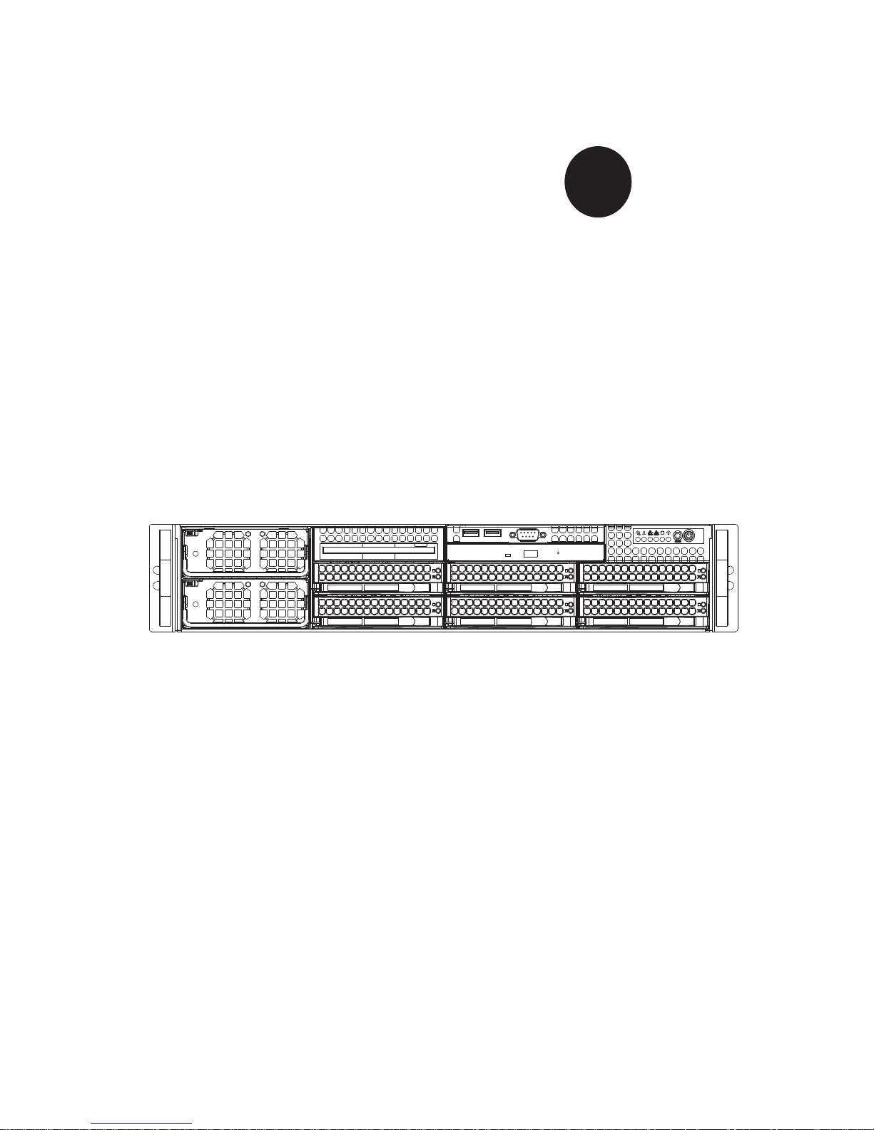
The SuperServer 8025C-3R is a high-end quad processor server based on the
SC828TQ-R1200 2U rackmount server chassis and the Super X7QC3 serverboard.
The X7QC3 supports four Intel® Xeon MP processors. Please refer to our web site
for an up-to-date list of supported processors.
Preface
Manual Organization
Chapter 1: Introduction
The fi rst chapter provides a checklist of the main components included with the
server system and describes the main features of the Super X7QC3 serverboard
and the SC828TQ-R1200 chassis.
Chapter 2: Server Installation
This chapter describes the steps necessary to install the SuperServer 8025C-3R into
a rack and check out the server confi guration prior to powering up the system. If your
server was ordered without the processor and memory components, this chapter will
refer you to the appropriate sections of the manual for their installation.
Chapter 3: System Interface
Refer to this chapter for details on the system interface, which includes the functions
and information provided by the control panel on the chassis as well as other LEDs
located throughout the system.
Chapter 4: System Safety
You should thoroughly familiarize yourself with this chapter for a general overview
of safety precautions that should be followed when installing and servicing the
SuperServer 8025C-3R.
iii

SUPERSERVER 8025C-3R User's Manual
Chapter 5: Advanced Serverboard Setup
Chapter 5 provides detailed information on the X7QC3 serverboard, including the
locations and functions of connectors, headers and jumpers. Refer to this chapter
when adding or removing processors or main memory and when reconfi guring the
serverboard.
Chapter 6: Advanced Chassis Setup
Refer to Chapter 6 for detailed information on the SC828TQ-R1200 2U rackmount
server chassis. You should follow the procedures given in this chapter when installing, removing or reconfi guring SAS or peripheral drives and when replacing system
power supply units and cooling fans.
Chapter 7: BIOS
The BIOS chapter includes an introduction to BIOS and provides detailed information on running the CMOS Setup Utility.
Appendix A: BIOS POST Messages
Appendix B: BIOS POST Codes
Appendix C: HostRAID Setup Guidelines
Appendix D: System Specifi cations
iv

Notes
Preface
v

SUPERSERVER 8025C-3R User's Manual
Table of Contents
Chapter 1 Introduction
1-1 Overview .........................................................................................................1-1
1-2 Serverboard Features .....................................................................................1-2
Processors ......................................................................................................1-2
Memory ...........................................................................................................1-2
Serial Attached SCSI (SAS) .......................................................................... 1-2
Serial ATA (SATA) .......................................................................................... 1-2
PCI Expansion Slots ....................................................................................... 1-2
Onboard Controllers/Ports .............................................................................. 1-3
ATI Graphics Controller ................................................................................... 1-3
IPMI .................................................................................................................1-3
Other Features ................................................................................................1-3
1-3 Server Chassis Features ................................................................................ 1-4
System Power .................................................................................................1-4
SAS Subsystem .............................................................................................. 1-4
Front Control Panel ......................................................................................... 1-4
I/O Backplane ..................................................................................................1-4
Cooling System ...............................................................................................1-4
1-4 Contacting Supermicro ....................................................................................1-6
Chapter 2 Server Installation
2-1 Overview .............................................................................................................2-1
2-2 Unpacking the System ....................................................................................2-1
2-3 Preparing for Setup ......................................................................................... 2-1
Choosing a Setup Location .............................................................................2-2
Rack Precautions ............................................................................................2-2
Server Precautions ..........................................................................................2-2
Rack Mounting Considerations .......................................................................2-3
Ambient Operating Temperature ................................................................ 2-3
Reduced Airfl ow ......................................................................................... 2-3
Mechanical Loading ................................................................................... 2-3
Circuit Overloading ..................................................................................... 2-3
Reliable Ground ......................................................................................... 2-3
2-4 Installing the System into a Rack ................................................................... 2-4
Identifying the Sections of the Rack Rails .....................................................2-4
Installing the Inner Rails ................................................................................. 2-4
Installing the Outer Rails .................................................................................2-4
vi

Table of Contents
Locking Tabs ..............................................................................................2-4
Installing the Server into the Rack ..................................................................2-5
2-5 Checking the Serverboard Setup ....................................................................2-6
2-6 Preparing to Power On ................................................................................... 2-7
Chapter 3 System Interface
3-1 Overview .........................................................................................................3-1
3-2 Control Panel Buttons .....................................................................................3-1
Reset ...............................................................................................................3-1
Power ..............................................................................................................3-1
3-3 Control Panel LEDs ........................................................................................3-2
Power Fail .......................................................................................................3-2
Overheat/Fan Fail ........................................................................................... 3-2
NIC2 ................................................................................................................3-2
NIC1 ................................................................................................................3-2
HDD ................................................................................................................. 3-3
Power ..............................................................................................................3-3
3-4 SAS Drive Carrier LEDs ................................................................................. 3-3
Chapter 4 System Safety
4-1 Electrical Safety Precautions .......................................................................... 4-1
4-2 General Safety Precautions ............................................................................4-2
4-3 ESD Precautions ............................................................................................. 4-3
4-4 Operating Precautions .................................................................................... 4-4
Chapter 5 Advanced Serverboard Setup
5-1 Handling the Serverboard ...............................................................................5-1
Precautions .....................................................................................................5-1
Unpacking .......................................................................................................5-2
5-2 Serverboard Installation ..................................................................................5-2
5-3 Connecting Cables .......................................................................................... 5-3
Connecting Data Cables .................................................................................5-3
Connecting Power Cables .............................................................................. 5-3
Connecting the Control Panel ......................................................................... 5-3
5-4 I/O Ports .......................................................................................................... 5-4
5-5 Installing the Processor and Heatsink ............................................................ 5-5
5-6 Installing Memory ............................................................................................5-8
Memory Support ..............................................................................................5-8
5-7 Adding PCI Add-On Cards ..............................................................................5-9
5-8 Serverboard Details ...................................................................................... 5-10
X7QC3 Quick Reference ...............................................................................5-11
vii

SUPERSERVER 8025C-3R User's Manual
5-9 Connector Defi nitions ................................................................................... 5-12
5-10 Jumper Settings ............................................................................................5-18
5-11 Onboard Indicators ........................................................................................5-22
5-12 Floppy, IDE, and SAS Ports ..........................................................................5-23
Chapter 6 Advanced Chassis Setup
6-1 Static-Sensitive Devices ..................................................................................6-1
Precautions .....................................................................................................6-1
6-2 Control Panel ..................................................................................................6-2
Unpacking .......................................................................................................6-2
6-3 System Fans ................................................................................................... 6-3
System Fan Failure ......................................................................................... 6-3
Replacing System Fans ..................................................................................6-3
6-4 Drive Bay Installation/Removal .......................................................................6-4
Accessing the Drive Bays ...............................................................................6-4
SAS Drive Installation ..................................................................................... 6-5
SAS Drive Backplane ......................................................................................6-7
6-5 Power Supply ..................................................................................................6-8
Power Supply Failure ...................................................................................... 6-8
Removing/Replacing the Power Supply ..........................................................6-8
Chapter 7 BIOS
7-1 Introduction ......................................................................................................7-1
Starting BIOS Setup Utility ..............................................................................7-1
7-2 Main Setup ......................................................................................................7-2
7-3 Advanced Settings .......................................................................................... 7-3
7-5 Security Settings ........................................................................................... 7-23
7-6 Exit Options ................................................................................................... 7-24
Appendix A BIOS POST Messages
Appendix B BIOS POST Codes
Appendix C HostRAID Setup Guidelines
Appendix D System Specifi cations
viii

Chapter 1: Introduction
Chapter 1
Introduction
1-1 Overview
The SuperServer 8025C-3R is a high-end server that is comprised of two main
subsystems: the SC828TQ-R1200 2U server chassis and the X7QC3 quad Intel
Xeon processor serverboard. Please refer to our web site for information on operating systems that have been certifi ed for use with the SuperServer 8025C-3R
(www.supermicro.com).
In addition to the serverboard and chassis, various hardware components have
been included with the SuperServer 8025C-3R, as listed below:
Six (6) 8-cm hot-swap chassis fans (FAN-0099L)
•
One (1) air shroud (MCP-310-82801-0N)•
One (1) air shroud (MCP-310-00032-00) •
One (1) slim DVD-ROM drive (DVM-PNSC-824B)•
One (1) IDE cable for DVD drive (CBL-0139L)•
One (1) rail set (MCP-290-00013-00) •
One (1) Super Server 8025C-3R User's Manual•
SAS Accessories •
One (1) SAS backplane (BPN-SAS-828TQ)
Two (2) SAS iPass cables (CBL-0188L)
Six (6) hot-swap drive carriers (MCP-220-00001-01)
1-1

SUPERSERVER 8025C-3R User's Manual
1-2 Serverboard Features
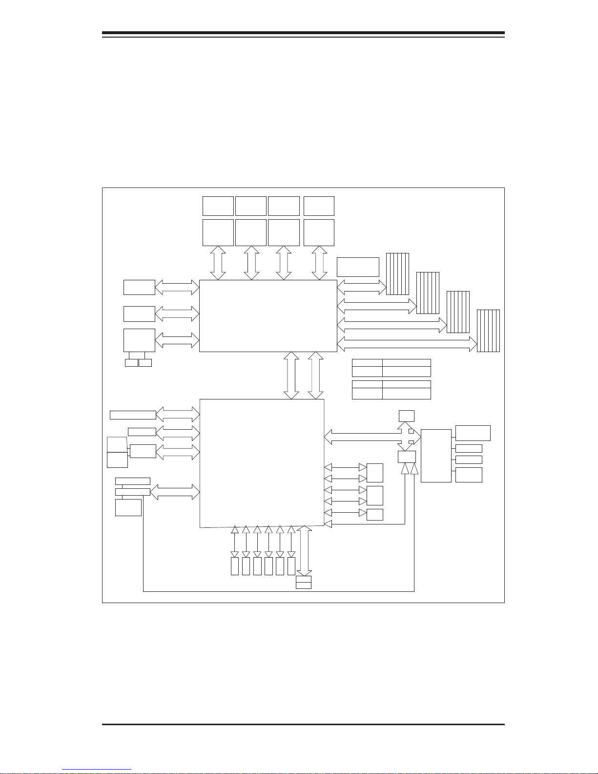
At the heart of the SuperServer 8025C-3R lies the X7QC3, a quad processor
serverboard based on the Intel 7300 chipset. Below are the main features of the
X7QC3. (See Figure 1-1 for a block diagram of the 7300 chipset).
Processors
The X7QC3 supports four Intel Xeon MP 7300/7200 Series processors. Please
refer to the serverboard description pages on our web site for a complete listing of
supported processors (www.supermicro.com).
Memory
The X7QC3 has 24 240-pin DIMM slots that can support up to 192 GB of ECC
FBD (Fully Buffered DIMM) DDR2-667/533 SDRAM. Single channel, two-channel
interleaved and four-channel interleaved memory are all supported. Modules of the
same size and speed should be used. See Chapter 5 Section 5 for details.
Serial Attached SCSI (SAS)
An onboard LSI-1068E Serial Attached SCSI (SAS) controller is integrated into
the X7QC3, which supports eight SAS hard drives with SES2. The SAS drives are
connected to a backplane that provides power, bus termination and confi guration
settings and are hot-swappable units. Note: The operati ng system you use mu st
have RAID support to enable the hot-swap capabilit y and RAI D function of the
SAS drive s. RA ID 0, 1 and 10 are sup por ted. (R AID 5 is al so suppor ted wi th an
optional i-Button installed.)
Serial ATA (SATA)
A SATA controller is integrated into the South Bridge (ESB2E) section of the chipset
to provide a six-port Serial ATA subsystem, which is RAID 0, 1, 10 and 5 supported.
The Serial ATA drives are hot-swappable units.
PCI Expansion Slots
The X7QC3 has two PCI-Express x8 slots, one PCI-Express x4 slot and one PCI-X
133 MHz slot. Only low-profi le cards are supported.
1-2

Chapter 1: Introduction
Onboard Controllers/Ports
One fl oppy drive controller and an onboard ATA/100 controller are provided to sup-
port up to two IDE hard drives or ATAPI devices (one IDE connection is reserved
for a Compact Flash card). The color-coded I/O ports include one COM port (an
additional COM header is located on the serverboard), a VGA (monitor) port, two
USB 2.0 ports, PS/2 mouse and keyboard ports and two Gb Ethernet ports.
ATI Graphics Controller
The X7QC3 features an integrated ATI video controller based on the ES1000 graphics chip. The ES1000 was designed specifi cally for servers, featuring low power
consumption, high reliability and superior longevity.
IPMI
IPMI (Intelligent Platform Management Interface) is a hardware-level interface specifi cation that provides remote access, monitoring and administration for Supermicro
server platforms. IPMI allows server administrators to view a server’s hardware
status remotely, receive an alarm automatically if a failure occurs, and power cycle
a system that is non-responsive. Optional add-on cards for IPMI use include the
AOC-SIMSO and the AOC-SIMSO+. An optional cable (CBL-0177L) must be used
for dedicated LAN. Please refer to our web page for the X7QC3 for more details.
Other Features
Other onboard features that promote system health include onboard voltage monitors, a chassis intrusion header, auto-switching voltage regulators, chassis and CPU
overheat sensors, virus protection and BIOS rescue.
1-3

SUPERSERVER 8025C-3R User's Manual
1-3 Server Chassis Features
The following is a general outline of the main features of the SC828TQ-R1200
server chassis.
System Power
The SC828TQ-R1200 features a redundant (two separate power modules) 1200W
high-effi ciency power supply with I
replace a failed power supply without shutting down the system.
SAS Subsystem
The SC828TQ-R1200 chassis was designed to suppor t six hot-swappable SAS
hard drives.
2
C. This power redundancy feature allows you to
Front Control Panel
The control panel on the SuperServer 8025C-3R provides you with system monitoring and control. LEDs indicate system power, HDD activity, network activity, system
overheat and power supply failure. A main power button and a system reset button
are also included. In addition, two USB ports and a COM port have been incorporated into the front of the chassis for convenient access.
I/O Backplane
The SC828TQ-R1200 is an ATX form factor chassis designed to be used in a 2U
rackmount confi guration. The I/O backplane includes one COM port, a VGA port,
two USB 2.0 ports, PS/2 mouse and keyboard ports and two gigabit Ethernet ports.
One standard size PCI expansion card may be added to the system.
Cooling System
The SC828TQ-R1200 chassis chassis has an innovative cooling design that includes six 4-cm counter-rotating fans located in the middle section of the chassis.
The power supply module also includes a cooling fan. All chassis and power supply
fans operate continuously. An air shroud channels the airfl ow from the system fans
to effi ciently cool the processors and memory.
1-4
Chapter 1: Introduction
Figure 1-1. Intel 7300 Chipset:
System Block Diagram
Note: This is a general block diagram. See Chapter 5 for details.
PCI-Ex16 Slot
PCI-Ex8 Slot
82575EB ZOAR
Dual GLANs
RJ45
RJ45
PCI-X 133 Slot (3.3V)
PCI-E x8 Slot
mini-S
AS
SAS x4
LSI-1068E
mini-S
AS
SAS x4
DB15
VGA Port
ATI ES1000
32MB DDR2
SDRAM
PCI-Ex8 (4GB/S)
PCI-Ex8 (4GB/S)
PCI-Ex4 (2GB/S)
PCI-X 133 (1GB/S)
PCI-Ex4 (2GB/S)
PCI-Ex8 (2GB/S)
PCI 32/33 (132MB/S)
CPU0
SOCKET P SOCKET P SOCKET P
PO RT
#4 & #5
PO RT
#6 & #7
PO RT
#1
PC I-X 133
PORT#0 (HCK)
PORT#1 (PEXH)
PORT#2 (PEXH)
VRD
VR11
Xeon MP
1067 MT/S
CPU0
VR11
.5GB/S
8
Intel 7300
NORTH BRIDGE
VRD CPU0
VR11
CPU 2CPU 1CPU 0
Xeon MPXeon MP
8.5GB/S
1067 MT/S
ESB2-E
VRD CPU0
1067 MT/S
PO RT
#2 & #3
PO
#4 X8
SOUTH BRIDGE
PC I 32/33
VR11
CPU 3
SOCKET P
Xeon MP
8.5GB/S
PO RT
#0
PC I-E x8 (4GB/S)
RT
PO
#3
ESB Interface
USB
VRD
8.5GB/S
1067 MT/S
PCI-E x4 "ESI" (2GB/S)
RT
17 GB/s for 533MHz
21 GB/s for 667MHz
FBD CH0 (8GB/S)
BRANCH 0
FBD CH1 (8GB/S)
FBD CH2 (8GB/S)
BRANCH 1
FBD CH3 (8GB/S)
NorthBound IN x14
DDR2-533
READ
WR
DDR2-667
READ
WRITE
LPC BUS
33MH
USB2.0Port0
480Mb/S
USB2.0Port1
480Mb/S
USB2.0Port2
480Mb/S
USB2.0 Port3
480Mb/S
USB2.0Port4
480Mb/S
USB2.0Port5
480Mb/S
SouthBound OUT
4.25GB/S
ITE
5.3GB/S
z x4b
JUSB 1
FRONT
USB
2
JUSB
AR
RE
US
B
JUSB3
B x1
US
10.7GB/S
BIOS
FWH
BMC
IPMI 2.0
x10
4 CHs1 CH
17GB/
8.5GB/S
4 CHs1 CH
21GB/S
W
S
SIO
Winbond
83627H
F
Backpanel
Serial Port
FDD
PS/2 KB/MS
Serial Port
SO L
3Gb/S
SATA II
SATA 5
3Gb/S
SATA II
SATA 4
SATA II
3Gb/S
SATA 3
3Gb/S
SATA II
SATA 2
3Gb/S
SATA II
SATA 1
3Gb/S
SATA II
SATA0
IDE- M
IDE- S
1-5
Primary IDE 133MB/S
TMDS

SUPERSERVER 8025C-3R User's Manual
1-4 Contacting Supermicro
Headquarters
Address: Super Micro Computer, Inc.
980 Rock Ave.
San Jose, CA 95131 U.S.A.
Tel: +1 (408) 503-8000
Fax: +1 (408) 503-8008
Email: marketing@supermicro.com (General Information)
support@supermicro.com (Technical Support)
Web Site: www.supermicro.com
Europe
Address: Super Micro Computer B.V.
Het Sterrenbeeld 28, 5215 ML
's-Hertogenbosch, The Netherlands
Tel: +31 (0) 73-6400390
Fax: +31 (0) 73-6416525
Email: sales@supermicro.nl (General Information)
support@supermicro.nl (Technical Support)
rma@supermicro.nl (Customer Support)
Asia-Pacifi c
Address: Super Micro Computer, Inc.
4F, No. 232-1, Liancheng Rd.
Chung-Ho 235, Taipei County
Taiwan, R.O.C.
Tel: +886-(2) 8226-3990
Fax: +886-(2) 8226-3991
Web Site: www.supermicro.com.tw
Technical Support:
Email: support@supermicro.com.tw
Tel: 886-2-8228-1366, ext.132 or 139
1-6

Chapter 2: Server Installation
Chapter 2
Server Installation
2-1 Overview
This chapter provides a quick setup checklist to get your 8025C-3R up and running. Following these steps in the order given should enable you to have the
system operational within a minimum amount of time. This quick setup assumes
that your system has come to you with the processors and memory preinstalled. If
your system is not already fully integrated with a serverboard, processors, system
memory etc., please turn to the chapter or section noted in each step for details
on installing specifi c components.
2-2 Unpacking the System
You should inspect the box the 8025C-3R was shipped in and note if it was damaged in any way. If the server itself shows damage you should fi le a damage claim
with the carrier who delivered it.
Decide on a suitable location for the rack unit that will hold the 8025C-3R. It should
be situated in a clean, dust-free area that is well ventilated. A void areas where heat,
electrical noise and electromagnetic fi elds are generated. Y ou will also need it placed
near a grounded power outlet. Be sure to read the Rack and Server Precautions
in the next section.
2-3 Preparing for Setup
The box the 8025C-3R was shipped in should include two sets of rail assemblies,
two rail mounting brackets and the mounting screws you will need to install the
system into the rack. Follow the steps in the order given to complete the installation
process in a minimum amount of time. Please read this section in its entirety before
you begin the installation procedure outlined in the sections that follow.
2-1
SUPERSERVER 8025C-3R User's Manual
Choosing a Setup Location
Leave enough clearance in front of the rack to enable you to open the front door •
completely (~25 inches) and approximately 30 inches of clearance in the back
of the rack to allow for suffi cient airfl ow and ease in servicing.
•
This product is for installation only in a Restricted Access Location (dedicated
equipment rooms, service closets and the like).
This product is not suitable for use with visual display work place devices
•
acccording to §2 of the the German Ordinance for Work with Visual Display
Units.
Warnings and Precautions!
Rack Precautions
Ensure that the leveling jacks on the bottom of the rack are fully extended to •
the fl oor with the full weight of the rack resting on them.
In single rack installation, stabilizers should be attached to the rack. In multiple
•
rack installations, the racks should be coupled together.
Always make sure the rack is stable before extending a component from the
•
rack.
You should extend only one component at a time - extending two or more si-
•
multaneously may cause the rack to become unstable.
Server Precautions
Review the electrical and general safety precautions in Chapter 4.•
Determine the placement of each component in the rack • before you install the
rails.
Install the heaviest server components on the bottom of the rack fi rst, and then
•
work up.
Use a regulating uninterruptible power supply (UPS) to protect the server from
•
power surges, voltage spikes and to keep your system operating in case of a
power failure.
2-2

Chapter 2: Server Installation
Allow the hot plug SAS drives and power supply modules to cool before touch-•
ing them.
Always keep the rack's front door and all panels and components on the servers
•
closed when not servicing to maintain proper cooling.
Rack Mounting Considerations
Ambient Operating Temperature
If installed in a closed or multi-unit rack assembly, the ambient operating temperature of the rack environment may be greater than the ambient temperature of the
room. Therefore, consideration should be given to installing the equipment in an
environment compatible with the manufacturer’s maximum rated ambient temperature (Tmra).
Reduced Airfl ow
Equipment should be mounted into a rack so that the amount of airfl ow required
for safe operation is not compromised.
Mechanical Loading
Equipment should be mounted into a rack so that a hazardous condition does not
arise due to uneven mechanical loading.
Circuit Overloading
Consideration should be given to the connection of the equipment to the power
supply circuitry and the effect that any possible overloading of circuits might have
on overcurrent protection and power supply wiring. Appropriate consideration of
equipment nameplate ratings should be used when addressing this concern.
Reliable Ground
A reliable ground must be maintained at all times. To ensure this, the rack itself
should be grounded. Particular attention should be given to power supply connections other than the direct connections to the branch circuit (i.e. the use of power
strips, etc.).
2-3

SUPERSERVER 8025C-3R User's Manual
2-4 Installing the System into a Rack
This section provides information on installing the 8025C-3R into a rack unit with
the rack rails provided. If the system has already been mounted into a rack, you can
skip ahead to Sections 2-5 and 2-6. There are a variety of rack units on the market,
which may mean the assembly procedure will differ slightly. You should also refer to
the installation instructions that came with the rack unit you are using.
Identifying the Sections of the Rack Rails
You should have received two rack rail assemblies in the rack mounting kit. Each
assembly consists of two sections: an inner fi xed chassis rail that secures directly
to the server chassis and an outer fi xed rack rail that secures directly to the rack
itself. Two pairs of short brackets to be used on the front side of the outer rails are
also included.
Installing the Inner Rails
Both the left and right side inner rails have been pre-attached to the chassis. Proceed to the next step.
Installing the Outer Rails
Begin by measuring the distance from the front rail to the rear rail of the rack. Attach
a short bracket to the front side of the right outer rail and a long bracket to the rear
side of the right outer rail. Adjust both the short and long brackets to the proper
distance so that the rail can fi t snugly into the rack. Secure the short bracket to the
front side of the outer rail with two M4 screws and the long bracket to the rear side
of the outer rail with three M4 screws. Repeat these steps for the left outer rail.
Locking Tabs
Both chassis rails have a locking tab, which serves two functions. The fi rst is to
lock the server into place when installed and pushed fully into the rack, which is
its normal position. Secondly, these tabs also lock the server in place when fully
extended from the rack. This prevents the server from coming completely out of
the rack when you pull it out for servicing.
2-4
Chapter 2: Server Installation
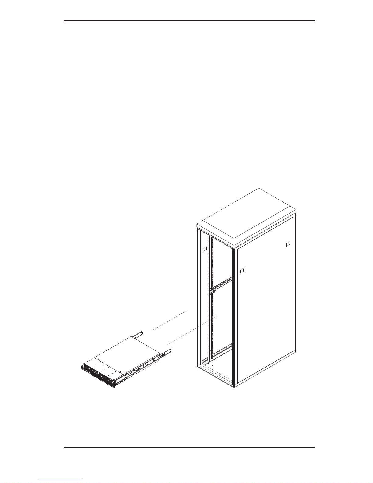
Installing the Server into the Rack
You should now have rails attached to both the chassis and the rack unit. The next
step is to install the server into the rack. Do this by lining up the rear of the chassis rails with the front of the rack rails. Slide the chassis rails into the rack rails,
keeping the pressure even on both sides (you may have to depress the locking
tabs when inserting). See Figure 2-1.
When the server has been pushed completely into the rack, you should hear the
locking tabs "click". Finish by inserting and tightening the thumbscrews that hold
the front of the server to the rack.
Figure 2-1. Installing the Server into a Rack
2-5

SUPERSERVER 8025C-3R User's Manual
2-5 Checking the Serverboard Setup
After you install the 8025C-3R in the rack, you will need to open the top cover to
make sure the serverboard is properly installed and all the connections have been
made.
Accessing the Inside of the System
First, release the retention screws that secure the system to the rack.1.
Grasp the two handles on either side and pull the system straight out until it 2.
locks (you will hear a "click").
Next, release the thumbscrew at the middle rear of the top cover. Then de-3.
press the two buttons on the top of the chassis to release the top cover.
Push the cover away from you (toward the rear of the chassis) until it stops. 4.
You can then lift the top cover from the chassis to gain full access to the
inside of the server.
To remove the system from the rack completely, depress the locking tabs in 5.
the chassis rails (push the right-side tab down and the left-side tab up) to
continue to pull the system out past the locked position.
Checking the Components and Setup
You may up to four processors already installed in the serverboard. Each 1.
processor needs its own heatsink. See Chapter 5 for instructions on processor and heatsink installation.
Your server system may have come with system memory already installed. 2.
Make sure all DIMMs are fully seated in their slots. For details on adding
system memory, refer to Chapter 5.
If desired, you can install an add-on card to the system. See Chapter 5 for 3.
details on installing PCI add-on cards.
Make sure all power and data cables are properly connected and not blocking 4.
the chassis airfl ow. See Chapter 5 for details on cable connections.
2-6

Chapter 2: Server Installation
2-6 Preparing to Power On
Next, you should check to make sure the peripheral drives and the SAS drives
and SAS backplane have been properly installed and all connections have been
made.
Checking the Drives
All drives are accessable from the front of the server. For servicing the DVD-1.
ROM and fl oppy drives, you will need to remove the top chassis cover. The
SAS disk drives can be installed and removed from the front of the chassis
without removing the top chassis cover.
A slim DVD-ROM and fl oppy drive should be preinstalled in your server. Refer 2.
to Chapter 6 if you need to reinstall a DVD-ROM and/or fl oppy disk drive to
the system.
Depending upon your system's confi guration, your system may have one or 3.
more drives already installed. If you need to install SAS drives, please refer to
Chapter 6.
Checking the Airfl ow
Airfl ow is provided by six sets of 4-cm fans (each set of fans consists of two 1.
fans that are mounted back to back) and an air shroud. The system component layout was carefully designed to direct suffi cient cooling airfl ow to the
components that generate the most heat.
Note that all power and data cables have been routed in such a way that they 2.
do not block the airfl ow generated by the fans.
Providing Power
Plug the power cords from the power supplies unit into a high-quality power 1.
strip that offers protection from electrical noise and power surges.
It is recommended that you use an uninterruptible power supply (UPS).2.
Finally, depress the power on button on the front of the chassis.3.
2-7

SUPERSERVER 8025C-3R User's Manual
Notes
2-8

Chapter 3: System Interface
Chapter 3
System Interface
3-1 Overview
There are several LEDs on the control panel as well as others on the SAS drive
carriers to keep you constantly informed of the overall status of the system as well
as the activity and health of specifi c components. There are also two buttons on
the chassis control panel and an on/off switch on the power supply. This chapter
explains the meanings of all LED indicators and the appropriate response you may
need to take.
3-2 Control Panel Buttons
There are two push-buttons located on the front of the chassis: a reset button and
a power on/off button.
Reset
Use the reset button to reboot the system.
Power
The main power button is used to apply or remove power from the power supply
to the server system. Turning off system power with this button removes the main
power but keeps standby power supplied to the system.
3-1
SUPERSERVER 8025C-3R User's Manual
3-3 Control Panel LEDs
The control panel located on the front of the SC828TQ-R1200 chassis has fi ve
LEDs. These LEDs provide you with critical information related to different parts of
the system. This section explains what each LED indicates when illuminated and
any corrective action you may need to take.
Power Fail
Indicates a power supply module has failed. The second power supply module will
take the load and keep the system running but the failed module will need to be
replaced. Refer to Chapter 6 for details on replacing the power supply. This LED
should be off when the system is operating normally
Overheat/Fan Fail
When this LED fl ashes it indicates a fan failure. When on continuously (on and not
fl ashing) it indicates an overheat condition, which may be caused by cables ob-
structing the airfl ow in the system or the ambient room temperature being too warm.
Check the routing of the cables and make sure all fans are present and operating
normally. You should also check to make sure that the chassis covers are installed.
Finally, verify that the heatsinks are installed properly (see Chapter 5). This LED
will remain fl ashing or on as long as the overheat condition exists.
2
NIC2
Indicates network activity on GLAN2 when fl ashing.
1
NIC1
Indicates network activity on GLAN1 when fl ashing.
3-2

Chapter 3: System Interface
HDD
Indic ates IDE chan nel activ ity. On the 8025 C-3 R this light ind icates SAS an d/or
DVD- ROM d rive ac tivit y when fl ashing.
Power
Indic ates power is bein g supplied to the sy stem's power supply u nits. This LED
should normally be illuminated when the system is operating.
3-4 SAS Drive Carrier LEDs
Each SAS drive carrier has two LEDs:
Green:
• When illuminated, the green LED on the front of the SAS drive carrier
indicates drive activity. A connection to the backplane enables this LED to blink
on and off when that particular drive is being accessed.
Red:
• The SES2 compliant backplane activates the red LED to indicate a drive
failure. If one of the SAS drives fail, you should be notifi ed by your system
management software. Please refer to Chapter 6 for instructions on replacing
failed SAS drives.
3-3

SUPERSERVER 8025C-3R User's Manual
Notes
3-4
Chapter 4: System Safety
!
Chapter 4
System Safety
4-1 Electrical Safety Precautions
Basic electrical safety precautions should be followed to protect yourself from harm
and the SuperServer 8025C-3R from damage:
Be aware of the locations of the power on/off switch on the chassis as well
•
as the room's emergency power-off switch, disconnection switch or electrical
outlet. If an electrical accident occurs, you can then quickly remove power from
the system.
Do not work alone when working with high voltage components.
•
Power should always be disconnected from the system when removing or in-•
stalling main system components, such as the serverboard, memory modules
and fl oppy drive. When disconnecting power, you should fi rst power down the
system with the operating system fi rst and then unplug the power cords of all
the power supply units in the system.
When working around exposed electrical circuits, another person who is familiar
•
with the power-off controls should be nearby to switch off the power if necessary.
Use only one hand when working with powered-on electrical equipment. This
•
is to avoid making a complete circuit, which will cause electrical shock. Use
extreme caution when using metal tools, which can easily damage any electrical
components or circuit boards they come into contact with.
Do not use mats designed to decrease static electrical discharge as protection
•
from electrical shock. Instead, use rubber mats that have been specifi cally
designed as electrical insulators.
The power supply power cords must include a grounding plug and must be
•
plugged into grounded electrical outlets.
4-1
SUPERSERVER 8025C-3R User's Manual
!
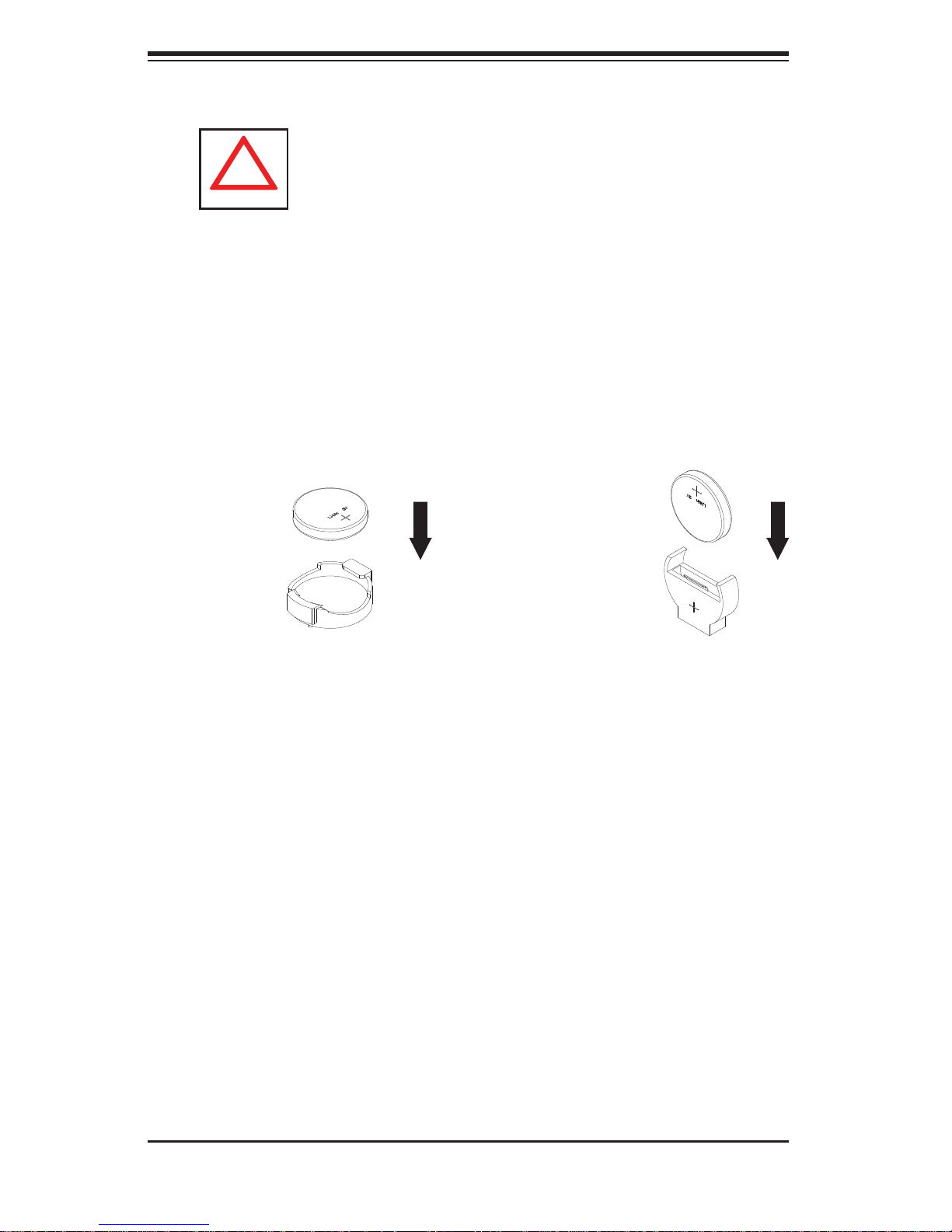
Serverboard Battery: • CAUTION - There is a danger of explosion if the onboard
battery is installed upside down, which will reverse its polarites (see Figure
4-1). This battery must be replaced only with the same or an equivalent type
recommended by the manufacturer. Dispose of used batteries according to the
manufacturer's instructions.
CD-ROM Laser:
• CAUTION - this server may have come equipped with a CD-
ROM drive. To prevent direct exposure to the laser beam and hazardous radiation exposure, do not open the enclosure or use the unit in any unconventional
way.
Mainboard replaceable soldered-in fuses: Self-resetting PTC (Positive Tempera-
•
ture Coeffi cient) fuses on the mainboard must be replaced by trained service
technicians only. The new fuse must be the same or equivalent as the one
replaced. Contact technical support for details and support.
4-2 General Safety Precautions
Follow these rules to ensure general safety:
Keep the area around the SuperServer 8025C-3R clean and free of clutter.
•
The SuperServer 8025C-3R weighs approximately 65.5 lbs. (29.8 kg) when fully •
loaded. When lifting the system, two people at either end should lift slowly with
their feet spread out to distribute the weight. Always keep your back straight
and lift with your legs.
Place the chassis top cover and any system components that have been re-
•
moved away from the system or on a table so that they won't accidentally be
stepped on.
While working on the system, do not wear loose clothing such as neckties and
•
unbuttoned shirt sleeves, which can come into contact with electrical circuits or
be pulled into a cooling fan.
Remove any jewelry or metal objects from your body, which are excellent metal
•
conductors that can create short circuits and harm you if they come into contact
with printed circuit boards or areas where power is present.
4-2
Chapter 4: System Safety
!
After accessing the inside of the system, close the system back up and secure •
it to the rack unit with the retention screws after ensuring that all connections
have been made.
4-3 ESD Precautions
Electrostatic discharge (ESD) is generated by two objects with different electrical
charges coming into contact with each other. An electrical discharge is created to
neutralize this difference, which can damage electronic com ponents and printed
circuit boards. The following measures are generally suffi cient to neutralize this
difference before contact is made to protect your equipment from ESD:
Use a grounded wrist strap designed to prevent static discharge.
•
Keep all components and printed circuit boards (PCBs) in their antistatic bags •
until ready for use.
Touch a grounded metal object before removing the board from the antistatic
•
bag.
Do not let components or PCBs come into contact with your clothing, which may
•
retain a charge even if you are wearing a wrist strap.
Handle a board by its edges only; do not touch its components, peripheral chips,
•
memory modules or contacts.
When handling chips or modules, avoid touching their pins.
•
Put the serverboard and peripherals back into their antistatic bags when not •
in use.
For grounding purposes, make sure your computer chassis provides excellent
•
conductivity between the power supply, the case, the mounting fasteners and
the serverboard.
4-3
SUPERSERVER 8025C-3R User's Manual
!
4-4 Operating Precautions
Care must be taken to assure that the chassis cover is in place when the 8025C-3R
is operating to assure proper cooling. Out of warranty damage to the system can
occur if this practice is not strictly followed.
Figure 4-1. Installing the Onboard Battery
LITHIUM BATTERY
LITHIUM BATTERY
OR
BATTERY HOLDER BATTERY HOLDER
4-4

Chapter 5: Advanced Serverboard Setup
Chapter 5
Advanced Serverboard Setup
This chapter covers the steps required to install the X7QC3 serverboard into
the chassis, connect the data and power cables and install add-on cards. All
serverboard jumpers and connections are also described. A layout and quick reference chart are included in this chapter for your reference. Remember to completely
close the chassis when you have fi nished working with the serverboard to better
cool and protect the system.
5-1 Handling the Serverboard
Electrostatic discharge (ESD) can damage electronic com ponents. To prevent damage to any printed circuit boards (PCBs), it is important to handle them very carefully
(see previous chapter). To prevent the serverboard from bending, keep one hand
under the center of the board to support it when handling. The following measures
are generally suffi cient to protect your equipment from electric static discharge.
Precautions
Use a grounded wrist strap designed to prevent Electrostatic Discharge •
(ESD).
Touch a grounded metal object before removing any board from its antistatic
•
bag.
Handle a board by its edges only; do not touch its components, peripheral chips,
•
memory modules or gold contacts.
When handling chips or modules, avoid touching their pins.
•
Put the serverboard, add-on cards and peripherals back into their antistatic •
bags when not in use.
For grounding purposes, make sure your computer chassis provides excellent
•
conductivity between the power supply, the case, the mounting fasteners and
the serverboard.
5-1

SUPERSERVER 8025C-3R User's Manual
Unpacking
The serverboard is shipped in antistatic packaging to avoid electrical static discharge. When unpacking the board, make sure the person handling it is static
protected.
5-2 Serverboard Installation
This section explains the fi rst step of physically mounting the X7QC3 into the
SC828TQ-R1200 chassis. Following the steps in the order given will eliminate
the most common problems encountered in such an installation. To remove the
serverboard, follow the procedure in reverse order.
Installing to the Chassis
Access the inside of the system by removing the screws from the back lip of 1.
the top cover of the chassis, then pull the cover off.
The X7QC3 requires a chassis big enough to support a 16" x 14.3" 2.
serverboard, such as Supermicro's SC828TQ-R1200 .
Make sure that the I/O ports on the serverboard align properly with their 3.
respective holes in the I/O shield at the back of the chassis.
Carefully mount the serverboard to the serverboard tray by aligning the board 4.
holes with the raised metal standoffs that are visible in the chassis.
Insert screws into all the mounting holes on your serverboard that line up 5.
with the standoffs and tighten until snug (if you screw them in too tight, you
might strip the threads). Metal screws provide an electrical contact to the
serverboard ground to provide a continuous ground for the system.
Finish by replacing the top cover of the chassis.6.
5-2

Chapter 5: Advanced Serverboard Setup
5-3 Connecting Cables
Now that the serverboard is installed, the next step is to connect the cables to the
board. These include the data (ribbon) cables for the peripherals and control panel
and the power cables.
Connecting Data Cables
The ribbon cables used to transfer data from the peripheral devices have been carefully routed to prevent them from blocking the fl ow of cooling air that moves through
the system from front to back. If you need to disconnect any of these cables, you
should take care to keep them routed as they were originally after reconnecting
them (make sure the red wires connect to the pin 1 locations). The following data
cables (with their locations noted) should be connected. (See the layout on page
5-9 for connector locations.)
SAS drive data cables (JSM1, JSM2)
•
Control Panel cable (JF1)•
DVD-ROM drive cable (J3)•
USB cable (USB5/6)•
COM port cable (COM2)•
Important! Make sure the cables do not come into contact with the fans.
Connecting Power Cables
The X7QC3 has a 24-pin primary power supply connector (JPW1) for connection
to the ATX power supply. In addition, there is an 8-pin secondary power connector
(JPW2) that also must be connected to your power supply (via a 4-pin connector).
See Section 5-9 for power connector pin defi nitions.
Connecting the Control Panel
JF1 contains header pins for various front control panel connectors. See Figure 5-1
for the pin locations of the various front control panel buttons and LED indicators.
5-3

SUPERSERVER 8025C-3R User's Manual
All JF1 wires have been bundled into a single ribbon cable to simplify this connection. Make sure the red wire plugs into pin 1 as marked on the board. The other
end connects to the Control Panel PCB board, located just behind the system status
LEDs on the chassis. See Chapter 5 for details and pin descriptions.
Figure 5-1. Control Panel Header Pins
20 19
Ground
NMI
x (Key)
Power On LED
HDD LED
NIC1 LED
NIC2 LED
OH/Fan Fail LED
Reserved
Ground
Ground
2 1
x (Key)
Vcc 5V Stby
Vcc 3V
Vcc 3V Stby
Vcc 3V Stby
Vcc 3V
Reserved
Reset (Button)
Power (Button)
5-4 I/O Ports
The I/O ports are color coded in conformance with the PC 99 specifi cation. See
Figure 5-2 below for the colors and locations of the various I/O ports.
Mouse (Green)
USB0/1 Ports
Keyboard
(Purple)
Figure 5-2. I/O Ports
COM1 Port
(Turquoise)
JLAN1/2 Ports
VGA Port
(Blue)
5-4

Chapter 5: Advanced Serverboard Setup
!
5-5 Installing the Processor and Heatsink
Avoid placing direct pressure to the top of the processor package. Always
remove the power cord fi rst before adding, removing or changing any
hardware components.
Notes: Always connect the power cord last and remove it before adding, removing or changing any components. Make sure to install the processor into the CPU
socket before you install the CPU heat sink.
Intel's boxed Xeon CPU package contains the CPU fan and heatsink assembly. If
you buy the CPUs separately, use only Intel-certifi ed heat sinks and fans.
Make sure to install the heat sink backplate and the serverboard into the chassis
before you install the CPU heat sink and fan (see below).
Inspect the Xeon 7300/7200 INT-mPGA CPU socket and make sure that the CPU
plastic cap is in place and none of the socket pins are bent. Otherwise, contact the
retailer immediately.
All graphics shown in this manual are for reference only. The component s that
came with your serverboard may or may not look exactly the same as the pictures
shown in this manual.
Installation Procedure
For proper system setup, please follow the procedure below:
Install the heatsink backplate into 1.
the chassis if needed
Install the serverboard into the 2.
chassis.
Heatsink
CPU
CPU Socket
Serverboard
Install the CPU(s).3.
Install the heat sink or/and cool-4.
ing fans (if any).
Connect fan and power cables.5.
Retention Bracket
(pre-installed)
Backplate
5-5

SUPERSERVER 8025C-3R User's Manual
!
CPU Installation
Lift the lever on the CPU socket 1.
completely as shown in the picture
on the right; otherwise, you will
damage the CPU socket when
power is applied. Note: if multiple
CPUs are installed,be sure to
install CPU1 fi rst.
Insert the CPU in the socket, 2.
making sure that pin 1 of the CPU
aligns with pin 1 of the socket
(both corners are marked with a
triangle). Note:When using only
one CPU, install it into CPU socket
#1. Please note that sockets #2,
#3 and #4 will be automatically
disabled if only one CPU is used.
Socket lever
Pin1
Press the lever down until you hear 3.
a *click*, indicating that the CPU
is securely installed in the CPU
socket.
Socket lever in the
locked position
Warning! Make sure you lift the lever completely when installing the CPU;
otherwise, damage to the socket or CPU may occur.
Figure 5-3. PGA604 Socket: Empty and with Processor Installed
Lever
Processor
Triangle
Triangles
5-6

Chapter 5: Advanced Serverboard Setup
!
Installation and Removal of the Heat Sink
CEK Heat Sink Installation
Do not apply any thermal grease to the 1.
heat sink or the CPU die; the required
amount has already been applied.
Place the heatsink on top of the CPU so 2.
that the four mounting holes are aligned
with those on the retention mechanism.
Screw in two diagonal screws (i.e. the #1 3.
and the #2 screws) until just snug (do not
over-tighten the screws, which may damage the CPU.)
Screw #1
Screw #2
Finish the installation by fully tightening all 4.
four screws.
Uninstalling the Heat Sink
Warning: We do not recommend removing the CPU or the heat sink.
However, if you do need to uninstall the heat sink, please follow these
instructions to avoid damaging the CPU or the CPU socket.
Unscrew and remove the heat sink 1.
screws in the sequence shown in the
picture on the right.
Hold the heat sink as shown in the picture 2.
on the right and gently wriggle to loosen
it from the CPU. (Do not use excessive
force when doing this!)
Once the heat sink is loosened, remove it 3.
from the CPU socket.
Screw #1
Screw #4
Screw #3
Screw #2
Clean the surface of the CPU and the 4.
heat sink to get rid of the old thermal
grease. Reapply the proper amount of
thermal grease before you re-install the
heat sink.
5-7

SUPERSERVER 8025C-3R User's Manual
!
5-6 Installing Memory
CAUTION! Exercise extreme care when installing or removing DIMM
modules to prevent any possible damage.
5-6 Installing Memory
Memory Support
The X7QC3 supports up to 192 GB fully buffered (FBD) ECC DDR2 667/533 in
24 DIMM slots (four channels, two branches). Single channel memory, two-way
interleaved memory and four-way interleaved memory schemes are all supported.
Using four-way interleaved memory will result in the best performance. Please use
memory modules of the same type, speed, and timing. Note: See the following
table for memory installation.
Installing Memory Modules
Insert the desired number of FBD DDR2 modules into the memory slots, start-1.
ing with DIMM #1A. To enhance memory performance, install pairs of memory
modules of the same type and of the same, beginning with DIMM #1A and
DIMM #2A, then DIMM #1B and DIMM #2B (see Memory Support above).
Insert each DIMM module vertically into its slot. Pay attention to the notch 2.
along the bottom of the module to avoid installing incorrectly (see Figure 5-4).
Gently press down on the DIMM module until it snaps into place in the slot. 3.
Repeat for all modules.
Memory Configuration Table
Branch 0
Channel 0 (Bank 0) Channel 1 (Bank 1)
2 DIMMs 1A --- --- --- --- --- 1B
4 DIMMs 1A --- --- --- --- --- 1B
8 DIMMs 1A 2A --- --- --- --- 1B
12
1A 2A 3A --- --- --- 1B
DIMMs
16
1A 2A 3A 4A --- --- 1B
DIMMs
18
1A 2A 3A 4A 5A --- 1B
DIMMs
24
1A 2A 3A 4A 5A 6A 1B
DIMMs
*Notes: i. “---“ = DIMM slot not populated. ii. Both FDB DDR 533MHz and 668MHz are supported;
however, please insert memory modules of the same type and speed, starting with Slot 1A. iii. Installing
pairs of memory modules of the same type and speed will result in Interleaved memory. Single-way,
Two-way Interleaved and four-way Interleaved memory schemes are supported. For best performance,
please install pairs of memory modules in both Branch 0 and Branch 1, which will result in four-way
interleaved memory scheme. iv. For memory to work properly, please follow the restrictions listed in the
table.
Branch 1
--- --- --- --- --- --- --- --- --- --- --- --- --- --- --- --- ---
--- --- --- --- --- 1C --- --- --- --- --- 1D --- --- --- --- ---
2B --- --- --- --- 1C 2C --- --- --- --- 1D 2D --- --- --- ---
2B 3B --- --- --- 1C 2C 3C --- --- --- 1D 2D 3D --- --- ---
2B 3B 4B --- --- 1C 2C 3C 4C --- --- 1D 2D 3D 4D --- ---
2B 3B 4B 5B --- 1C 2C 3C 4C 5C --- 1D 2D 3D 4D 5D ---
2B 3B 4B 5B 6B 1C 2C 3C 4C 5C 6C 1D 2D 3D 4D 5D 6D
Channel 2 (Bank 2) Channel 3 (Bank 3)
5-8

Chapter 5: Advanced Serverboard Setup
Figure 5-4. DIMM Installation
DDR2 FBD DIMM
To Install: Insert module vertically and press down until it snaps into place. Pay attention to the bottom
notches.
To Remove: Use your thumbs to gently push each release tab outward to free the DIMM from the
slot.
5-7 Adding PCI Add-On Cards
The 8025C-3R can accommodate low-profi le (only) add-on cards installed into all
the PCI slots included on the X7QC3.
Installing an Add-on Card
Begin by removing the PCI slot shield for the slot you wish to populate.1.
Fully seat the card into the riser card slot, pushing down with your thumbs 2.
evenly on both sides of the card.
Finish by using a screw to secure the top of the card shield to the chassis. 3.
The PCI slot shields protect the serverboard and its components from EMI
and aid in proper ventilation, so make sure there is always a shield covering
each unused slot.
5-9

SUPERSERVER 8025C-3R User's Manual
5-8 Serverboard Details
Figure 5-5. X7QC3 Layout
(not drawn to scale)
JKM1
JVGA1
FAN9
X7QC3
JCOM2
JCOM1
LAN
CTRL
S I/O
Battery
JUSB1
FAN8
GLAN1
GLAN2
JPL1
FAN7
DIMM 6A(Branch 0 Channel 0)
DIMM 5A (Branch 0 Channel 0)
DIMM 4A (Branch 0 Channel 0)
DIMM 3A (Branch 0 Channel 0)
DIMM 2A (Branch 0 Channel 0)
DIMM 1A (Branch 0 Channel 0)
DIMM 6B (Branch 0 Channel 1)
DIMM 5B (Branch 0 Channel 1)
DIMM 4B (Branch 0 Channel 1)
DIMM 3B (Branch 0 Channel 1)
DIMM 2B (Branch 0 Channel 1)
DIMM 1B (Branch 0 Channel 1)
DIMM 6C (Branch 1 Channel 2)
DIMM 5C (Branch 1 Channel 2)
DIMM 4C (Branch 1 Channel 2)
DIMM 3C (Branch 1 Channel 2)
DIMM 2C (Branch 1 Channel 2)
DIMM 1C (Branch 1 Channel 2)
DIMM 6D (Branch 1 Channel 3)
DIMM 5D (Branch 1 Channel 3)
DIMM 4D (Branch 1 Channel 3)
DIMM 3D (Branch 1 Channel 3)
DIMM 2D (Branch 1 Channel 3)
DIMM 1D (Branch 1 Channel 3)
PCI Slot6 PCI-E x8 (in x16 slot)
PCI Slot5 PCI-E x4 (in x8 Slot)
PCI S
lot
4 PCI-X 133MHz
PCI S
lot3 PCI-E X8 (in X8 slot)
JK1
JP5
I-Button
JPS1
JWOR1
JPS2
SAS
JBT1
JD1
SP1
SAS-4i #4~#7
JSM2
LES1
JSM1
SAS-4i #0~#3
LES2
JUSB2
Intel ESB2
South
Bridge
JL1
J12
JWOL1
Intel 7300
North Bridge
J11
J10
J3P1
J15
J16
J14
JP4
JP13
JP2
JAR
JS1
JS2
SIMSO
CPLED1
CPLED2
JS4
JS3
VGA
CTRL
CPLED0
JPG1
CPU1
CPU3
JS6
JS5
J19
J13
CPU2
CPU4
JWF1
JIDE2
J17
LE1
JF1
FAN6
FAN5
J6
J8
FAN4
FAN3
J9
J7
FAN2
JIDE1
JPW1
JCF1
JPW3
JPW2
5-10

Chapter 5: Advanced Serverboard Setup
X7QC3 Quick Reference
Jumper Description Default Setting
J10/J11 SMB to PCI Slots #3/#4/#5/#6 Both Open (Disabled)
JBT1 CMOS Clear (See Section 5-10)
JCF1 Compact Flash Card Master/Slave Pins 1-2 (Master)
JP5 CPU PWR Select Open (130W for 2U)
JP13 3rd Power Supply Fail Detect Open (Disabled)
JPG1 VGA Enable/Disable Pins 1-2 (Enabled)
JPL1 GLAN1/2 Enable/Disable Pins 1-2 (Enabled)
JPS1 SAS/SATA (JSM1/JSM2) En/Disable Pins 1-2 (Enabled)
JPS2 SAS/SATA RAID Mode Closed(Integrated RAID)
JWD Watch Dog Pins 1-2 (Reset)
Connector Description
FAN 1-9 Chassis/CPU Fan Headers
GLAN1/2 Gigabit Ethernet (RJ45) Ports
J12 IPMB Header (of the IPMI module)
J13 PWR SMBus I
2
C Connector
J15/J16 Serial General Purpose Input/Output Headers
J17 Floppy Disk Drive Connector
J19 SIMSO Slot
J3P1 PWR Supply Fail LED
JAR Alarm Rest Header
JCOM1/JCOM2 COM1 Serial Port/Header
JD1 Onboard Speaker/Power LED
JF1 Front Panel Connector
JIDE1/JIDE2 IDE Drive/Compact Flash Card Connector
JL1 Chassis Intrusion Header
JOH1 Overheat Warning Header
JPW1 24-pin ATX Power Connector
JPW2/JPW3 +12V 8-Pin Processor Power Connectors
JS1~6 SATA Ports 1~6
JSM1/JSM2 SAS/SATA Ports #0-3/SAS/SATA Ports #4-7
JUSB1/2/3 Universal Serial Bus (USB) Ports/Headers
JWF1 Compact Flash Card Power Connector
JWOL1 Wake-On-LAN Header
JWOR1 Wake-On-Ring Header
5-11

SUPERSERVER 8025C-3R User's Manual
5-9 Connector Defi nitions
Main ATX Power Supply
Connector
The primary power supply connector
(JPW1) meets the SSI (Superset ATX)
24-pin specifi cation. Refer to the table
on the right for the pin defi nitions of
the ATX 24-pin power connector. You
must also connect the 8-pin (JPW2/
JPW3) processor power connectors to
your power supply (see below).
Processor Power Connector
JPW2 and JPW3 must also be connected to the power supply to provide
power for the processors. See the
table on the right for pin defi nitions.
ATX Power 24-pin Connector
Pin Defi nitions (JPW1)
Pin# Defi nition Pin # Defi nition
13 +3.3V 1 +3.3V
14 -12V 2 +3.3V
15 COM 3 COM
16 PS_ON 4 +5V
17 COM 5 COM
18 COM 6 +5V
19 COM 7 COM
20 Res (NC) 8 PWR_OK
21 +5V 9 5VSB
22 +5V 10 +12V
23 +5V 11 +12V
24 COM 12 +3.3V
+12V 8-pin Power
Pin Defi nitions (JPW2/JPW3)
Pins Defi nition
1 - 4 Ground
5 - 8 +12V
Required Connection
PW_ON Connector
The PW_ON connector is on pins 1
and 2 of JF1. This header should be
connected to the chassis power button. See the table on the right for pin
defi nitions.
Reset Connector
The reset connector is located on pins
3 and 4 of JF1 and attaches to the
reset switch on the computer chassis. See the table on the right for pin
defi nitions.
Power Button
Pin Defi nitions (JF1)
Pin# Defi nition
1 PW_ON
2 Ground
Reset Button
Pin Defi nitions (JF1)
Pin# Defi nition
3 Reset
4 Ground
5-12

Chapter 5: Advanced Serverboard Setup
Overheat/Fan Fail LED (OH)
Connect an LED to the OH connection
on pins 7 and 8 of JF1 to provide advanced warning of chassis overheating. Refer to the table on the right for
pin defi nitions.
NIC2 (JLAN2) LED
The LED connections for JLAN2 are
on pins 9 and 10 of JF1. Attach an
LED cable to display network activity. See the table on the right for pin
defi nitions.
OH/Fan Fail LED
Pin Defi nitions (JF1)
Pin# Defi nition
7 Vcc
8 Ground
Pin Defi nitions (JF1)
Pin# Defi nition
9 Vcc
10 Ground
OH/Fan Fail Indicator
Status
State Defi nition
Off Normal
On Overheat
Flash-
ing
NIC2 LED
Fan Fail
NIC1 (JLAN1) LED
The LED connections for JLAN1 are
on pins 11 and 12 of JF1. Attach an
LED cable to display network activity. See the table on the right for pin
defi nitions.
HDD LED
The HDD LED connection is located
on pins 13 and 14 of JF1. This LED
is used to display all IDE and SAS
activity. See the table on the right for
pin defi nitions.
NIC1 LED
Pin Defi nitions (JF1)
Pin# Defi nition
11 Vcc
12 Ground
HDD LED
Pin Defi nitions (JF1)
Pin# Defi nition
13 Vcc
14 HD Active
5-13

SUPERSERVER 8025C-3R User's Manual
Power On LED
The Power On LED connector is located on pins 15 and 16 of JF1 (use
JLED for a 3-pin connector). This
connection is used to provide LED
indication of power being supplied to
the system. See the table on the right
for pin defi nitions.
NMI Button
The non-maskable interrupt button
header is located on pins 19 and 20
of JF1. Refer to the table on the right
for pin defi nitions.
Fan Headers
Power LED
Pin Defi nitions (JF1)
Pin# Defi nition
15 5V Stby
16 Control
NMI Button
Pin Defi nitions (JF1)
Pin# Defi nition
19 Control
20 Ground
There are nine fan headers on the
serverboard, all of which are 4-pin
fans. However, pins 1-3 of the fan
headers are backward compatible
with the traditional 3-pin fans. See
the table on the right for pin defi ni-
tions. The onboard fan speeds are
controlled by Thermal Management
(via Hardwa re Monitori ng) under t he
Advanced Section in the BIOS. The
default is disabled. When using Thermal Management setting, please use
all 3 -pin f ans or al l 4- pin fa ns.
ATX PS/2 Keyboard and PS/2
Mouse Ports
The ATX PS/2 keyboard and the PS/2
mouse are located on JKM1. The
mouse port is above the keyboard
port. See the table on the right for pin
defi nitions.
Fan Header
Pin Defi nitions
(FAN1-9)
Pin# Defi nition
1 Ground (Black)
2 +12V (Red)
3 Tachometer
4 PWM Control
PS/2 Keyboard and
Mouse Port Pin
Defi nitions (J28)
Pin# Defi nition
1 Data
2NC
3 Ground
4 VCC
5 Clock
6NC
5-14

Chapter 5: Advanced Serverboard Setup
Chassis Intrusion
The Chassis Intrusion header is designated JL1. Attach an appropriate
cable from the chassis to inform you
of a chassis intrusion when the chassis is opened
Wake-On-LAN
The Wake-On-LAN header is designated JWOL1 on the serverboard.
See the table on the right for pin
defi nitions. You must also have a LAN
card with a Wake-On-LAN connector
and cable to use this feature.
Wake-On-Ring
The Wake-On-Ring header is designated JWOR1. This function allows
your computer to receive and be
"awakened" by an incoming call when
in the suspend state. See the table on
the right for pin defi nitions. You must
also have a WOR card and cable to
use this feature.
Chassis Intrusion
Pin Defi nitions (JL1)
Pin# Defi nition
1 Intrusion Input
2 Ground
Wake-On-LAN
Pin Defi nitions
(JWOL1)
Pin# Defi nition
1 +5V Standby
2 Ground
3 Wake-up
Wake-On-Ring
Pin Defi nitions
(JWOR1)
Pin# Defi nition
1 Ground (Black)
2 Wake-up
Power Supply Fail LED
Connect a cable from your power
supply to J3P1 to provide warning of
power supply failure. This warning signal is passed through the PWR_LED
pin to indicate of a power failure on the
chassis. See the table on the right for
pin defi nitions.
GLAN1/2 (Ethernet Ports)
Two Ethernet ports (designated GLAN1
and GLAN2) are located beside the
VGA port on the I/O backplane. These
ports accept RJ45 type cables.
5-15
PWR Supply Fail LED
Pin Defi nitions (J3P1)
Pin# Defi nition
1 PWR 1: Fail
2 PWR 2: Fail
3 PWR 3: Fail
4 Signal: Alarm Reset
Note: This feature is only available when using Supermicro redundant power supplies.

SUPERSERVER 8025C-3R User's Manual
Serial Ports
Two serial ports are included on the
serverboard. COM1 is a backpanel
port and COM2 is a header located
near the onboard battery. See the
table on the right for pin defi nitions.
Power LED/Speaker
On JD1 header, pins 1-3 are for a
power LED and pins 4-7 are for the
speaker. Close pins 4-7 with a jumper
to use an external speaker. If you wish
to use the onboard speaker, please
close pins 6-7. See the table on the
right for speaker pin defi nitions.
Serial Port Pin Defi nitions
(COM1/COM2)
Pin # Defi nition Pin # Defi nition
1 DCD 6 DSR
2 RXD 7 RTS
3 TXD 8 CTS
4 DTR 9 RI
5 Ground 10 NC
Power LED/Speaker
Connector (JD1)
Pin Setting Defi nition
Pins 6-7 Internal Speaker
Pins 4-7 External Speaker
Universal Serial Bus (USB)
There are two Universal Serial Bus
ports located on the I/O panel and
three additional USB headers located
on the serverboard. The headers can
be used to provide front side USB
access (cables not included). See the
table on the right for pin defi nitions.
SGPIO Header
The SGPIO (Serial General Purpose
Input/Output) headers are located at
J15/J16. These headers are used to
communicate with a system-monitoring chip on the backplane. See the
table on the right for pin defi nitions.
Universal Serial Bus
Pin Defi nitions (USB)
USB0/1
Pin # Defi nition
1 +5V 1 +5V
2 PO- 2 PO3 PO+ 3 PO+
4 Ground 4 Ground
5 N/A 5 Key
SGPIO Header
Pin Defi nitions (J15/J16)
Pin# Defi nition Pin Defi nition
1 *NC 2 *NC
3 Ground 4 DATA Out
5 Load 6 Ground
7 Clock 8 *NC
USB2/3/4
Pin # Defi nition
NC = No Connection
5-16

Alarm Reset
If three power supplies are installed,
the system can notify you when any of
the three power modules fail. Connect
JAR to a micro-switch to enable you
to turn off the alarm that is activated
when a power module fails. See the
table on the right for pin defi nitions.
Chapter 5: Advanced Serverboard Setup
Alarm Reset Header
Pin Defi nitions (JAR)
Pin Setting Defi nition
Pin 1 Ground
Pin 2 +5V
Power SMB (I2C) Connector
Power SMB (I
2
C) connector, located
at J13, monitors the status of the
power supply, fan and system temperature. See the table on the right
for pin defi nitions.
Compact Flash Card PWR
Connector
A Compact Flash Card Power Connector is located at JWF1. For the
Compact Flash Card to work properly ,
you will need to enable with JCF1 and
connect a Compact Flash Card power
cable to JWF1 fi rst.
PWR SMB Header
Pin Defi nitions (J13)
Pin# Defi nition
1 Clock
2 Data
3 PWR Fail (Input from PS to MB)
4 Ground
5 +3.3V
Compact Flash Card PWR
Connector (JWF1)
Jumper Defi nition
On Compact Flash
Power On
Off Compact Flash
Power Off
Overheat LED/Fan Fail (JOH1)
The JOH1 header is used to connect
an LED to provide warning of chassis
overheating. This LED will blink to indicate a fan failure. Refer to the table
on right for pin defi nitions.
OH/Fan Fail LED
States
State Message
Solid Overheat
Blinking Fan Fail
5-17
Overheat LED
Pin Defi nitions (JOH1)
Pin# Defi nition
1 5vDC
2 OH Active

SUPERSERVER 8025C-3R User's Manual
Keylock
The keyboard lock connection is designated
JK1. Utilizing this header allows you to inhibit
any actions made on the keyboard, effectively
"locking" it.
IPMB Header
The IPMB Header of IPMI is designated J12.
See the table on right for pin defi nitions.
Keylock
Pin Defi nitions (JK1)
Pin# Defi nition
1 Ground
2 Keylock R-N
IPMB Header
Pin Defi nitions (J12)
Pin# Defi nition
1 SDATA
2 GND
3 SCLK
4NC
5-10 Jumper Settings
Explanation of Jumpers
To modify the operation of the
serverboard, jumpers can be used
to choose between optional settings.
Jumpers create shorts between two
pins to change the function of the connector. Pin 1 is identifi ed with a square
solder pad on the printed circuit board.
See the serverboard layout pages for
jumper locations.
Note: On a two-pin jumper, "Closed"
means the jumper is on both pins and
"Open" means the jumper is either on
only one pin or completely removed.
3 2 1
Connector
Pins
Jumper
3 2 1
Setting
5-18

Chapter 5: Advanced Serverboard Setup
CMOS Clear
JBT1 is used to clear CMOS (which will also clear any passwords). Instead of pins,
this jumper consists of contact pads to prevent accidentally clearing the contents
of CMOS.
To clear CMOS,
First power down the system and unplug the power cord(s).1.
With the power disconnected, short the CMOS pads with a metal object such 2.
as a small screwdriver.
Remove the screwdriver (or shorting device).3.
Reconnect the power cord(s) and power on the system.4.
Note: Do not use the PW_ON connector to clear CMOS.
VGA Enable/Disable
JPG1 allows you to enable or disable
the VGA port. The default position is on
pins 1 and 2 to enable VGA. See the
table on the right for jumper settings.
GLAN1/2 Enable/Disable
Change the setting of jumper JPL1 to
enable or disable the GLAN1/GLAN2
Ethernets port on the serverboard. See
the table on the right for jumper settings. The default setting is enabled.
3rd Power supply Fail Detect
The system can notify you in the event
of a power supply failure. This feature
is available when three power supply
units are installed in the chassis with
one acting as a backup. If you only have
one or two power supply units installed,
you should disable this detection feature
(the default setting) with JP13 to prevent
false alarms.
VGA Enable/Disable
Jumper Settings (JPG1)
Jumper Setting Defi nition
Pins 1-2 Enabled
Pins 2-3 Disabled
GLAN1/2 Enable/Disable
Jumper Settings (JPL1)
Jumper Setting Defi nition
Pins 1-2 Enabled
Pins 2-3 Disabled
3rd Power Supply Fail Detect
Jumper Settings (JP13)
Jumper Setting Defi nition
Closed Enabled
Open Disabled
5-19

SUPERSERVER 8025C-3R User's Manual
Watch Dog Enable/Disable
JWD controls the Watch Dog function.
Watch Dog is a system monitor that
can reboot the system when a software
application hangs. Jumping pins 1-2
will cause WD to reset the system if an
application hangs. Jumping pins 2-3
will generate a non-maskable interrupt
signal for the application that hangs.
See the table on the right for jumper
settings. Watch Dog must also be enabled in BIOS.
Note: When enabled, the user needs to
write their own application software in
order to disable the Watch Dog Timer.
Watch Dog
Jumper Settings (JWD)
Jumper Setting Defi nition
Pins 1-2 Reset
Pins 2-3 NMI
Open Disabled
Compact Flash Master/Slave Select
A Compact Flash Master (Primary)/
Slave (Secondary) Select Jumper is
located at JCF1. Close this jumper to
enable Compact Flash Card. For the
Compact Flash Card or the Compact
Flash Jumper (JCF1) to work properly,
you will need to connect the Compact
Flash Card power cable to JWF1 fi rst.
Refer to the board layout below for the
location.
I2C Bus to PCI-X/PCI-Exp. Slots
Jumpers J10 and J11 allow you to connect the System Management Bus (I
2
C)
to PCI-X/PCI-E slots 3/4/5/6. The default
setting is Open (Disabled.) Both jumpers
must be set to the same setting See the
table on the right for jumper settings.
Compact Flash Card Master/
Slave Select (JCF1)
Jumper Defi nition
Open Slave (Secondary)
Closed Master (Primary)
I2C to PCI-X/PCI-E Slots
Jumper Settings (J10/J11)
Jumper Setting Defi nition
J10: Closed J11:Closed Enabled
J10: Open J11: Open Disabled
5-20

Chapter 5: Advanced Serverboard Setup
SAS/SATA Enable/Disable
JPS1 allows you to enable or disable
the JSM1 and JSM2 ports, which may
be used for either SAS or SATA HDDs.
See the table on the right for jumper
settings.
RAID Mode
JPS2 allows you to switch between the
two RAID modes available: MegaRAID
and Integrated RAID (the latter requires
you to refresh the fi rmware). See the
table on the right for jumper settings.
SAS/SATA Enable/Disable
Jumper Settings (JPS1)
Jumper Setting Defi nition
Pins 1-2 SAS/SATA Enabled
Pins 2-3 SAS/SATA Disabled
RAID Mode
Jumper Settings (JPS2)
Jumper Setting Defi nition
Closed MegaRAID
Open Integrated RAID
CPU Power Select
JP5 allows you to select the CPU power
settings. The default position is "Open"
to support 130 W for 2U systems.
See the table on the right for jumper
settings.
CPU PWR Select
Jumper Settings (JP5)
Jumper Setting Defi nition
Open 130W for 2U Platform
Closed 80W for 1U Platform
5-21

SUPERSERVER 8025C-3R User's Manual
5-11 Onboard Indicators
GLAN1/2 LEDs
The Ethernet ports (located beside
the VGA port) have two LEDs. On
each port, one LED indicates activity
while the other LED may be green,
amber or off to indicate the speed of
the connection. See the table on the
right for the functions associated with
the connection speed LED.
Onboard Power LED (LE1)
An Onboard Power LED is located at
LE1. This LED Indicator is on when
the system is on. Be sure to unplug
the power cable before removing or
adding any components. See the table
on the right for more details.
(Connection Speed Indicator)
LED Color Defi nition
Off 10 MHz
Green 100 MHz
Amber 1 GHz
Onboard PWR LED Indicator
LED Color Defi nition
Off System Off (PWR cable
Green System On
Green:
Flashing
Quickly
Green:
Flashing
Slowly
GLAN1/2 LED
(LE1)
not connected)
ACPI S1 State
ACPI S3 (STR) State
SAS Activity LED
LES1 is used to indicate the status of
SAS activity.
SAS Heartbeat LED
A SAS Heartbeat LED is located at
LES2. When on, it indicates that the
LSI1068E SAS controller is operating.
5-22
SAS Activity LED Indicator
(LES1)
LED Color Defi nition
On SAS Port Active
Off SAS Port Inactive

Chapter 5: Advanced Serverboard Setup
5-12 Floppy, IDE, and SAS Ports
Use the following information to connect the IDE hard disk drive cables.
•
A red mark on a wire typically designates the location of pin 1.
The 80-wire ATA100/66 IDE hard disk drive cable that came with your system •
has two connectors to support two drives. This special cable should be used
to take advantage of the speed this new technology offers. The blue connector
connects to the onboard IDE connector interface and the other connector(s) to
your hard drive(s). Consult the documentation that came with your disk drive for
details on actual jumper locations and settings for the hard disk drive.
Floppy Connector
The fl oppy connector is located at
J17. See the table below for pin
defi nitions.
Floppy Drive Connector
Pin Defi nitions (J17)
Pin# Defi nition Pin # Defi nition
1 Ground 2 FDHDIN
3 Ground 4 Reserved
5 Key 6 FDEDIN
7 Ground 8 Index
9 Ground 10 Motor Enable
11 Ground 12 Drive Select B
13 Ground 14 Drive Select B
15 Ground 16 Motor Enable
17 Ground 18 DIR
19 Ground 20 STEP
21 Ground 22 Write Data
23 Ground 24 Write Gate
25 Ground 26 Track 00
27 Ground 28 Write Protect
29 Ground 30 Read Data
31 Ground 32 Side 1 Select
33 Ground 34 Diskette
5-23

SUPERSERVER 8025C-3R User's Manual
IDE Connectors
There are two IDE Connectors
(JIDE1: Blue, JIDE2: White)
on the serverboard. JIDE1 is
designated as the Primary IDE
drive. JIDE2 is designated as
the Secondary IDE drive and
is reserved for Compact Flash
Card use only. (See the note
below.) See the table on the
right for pin defi nitions.
Note: JIDE2 (the white slot)
is reserved for Compact Flash
Card only. Do not use it for
other devices. If JIDE2 is populated with a Compact Flash
Card, JIDE1 (the blue slot) will
be available for one device
only. For the Compact Flash
Card to work properly, you will
need to connect a power cable
to JWF1 fi rst.
IDE Drive Connectors
Pin Defi nitions (JIDE1/JIDE2)
Pin# Defi nition Pin # Defi nition
1 Reset IDE 2 Ground
3 Host Data 7 4 Host Data 8
5 Host Data 6 6 Host Data 9
7 Host Data 5 8 Host Data 10
9 Host Data 4 10 Host Data 11
11 Host Data 3 12 Host Data 12
13 Host Data 2 14 Host Data 13
15 Host Data 1 16 Host Data 14
17 Host Data 0 18 Host Data 15
19 Ground 20 Key
21 DRQ3 22 Ground
23 I/O Write 24 Ground
25 I/O Read 26 Ground
27 IOCHRDY 28 BALE
29 DACK3 30 Ground
31 IRQ14 32 IOCS16
33 Addr1 34 Ground
35 Addr0 36 Addr2
37 Chip Select 0 38 Chip Select 1
39 Activity 40 Ground
SATA Ports
There are no jumpers to confi g-
ure the onboard SATA connectors. See the table on the right
for pin defi nitions.
SATA Ports
Pin Defi nitions (JS1-JS6)
Pin # Defi nition
1 Ground
2 TXP
3 TXN
4 Ground
5 RXN
6 RXP
7 Ground
5-24

Chapter 6: Advanced Chassis Setup
Chapter 6
Advanced Chassis Setup
This chapter covers the steps required to install components and perform maintenance on the SC828TQ-R1200 chassis. For component installation, follow the steps
in the order given to eliminate the most common problems encountered. If some
steps are unnecessary, skip ahead to the step that follows.
Tools Required: The only tool you will need to install components and perform
maintenance is a Philips screwdriver.
6-1 Static-Sensitive Devices
Electrostatic discharge (ESD) can damage electronic com ponents. To prevent
damage to any printed circuit boards (PCBs), it is important to handle them very
carefully. The following measures are generally suffi cient to protect your equipment
from ESD damage.
Precautions
Use a grounded wrist strap designed to prevent static discharge.•
Touch a grounded metal object before removing any board from its antistatic •
bag.
Handle a board by its edges only; do not touch its components, peripheral chips,
•
memory modules or gold contacts.
When handling chips or modules, avoid touching their pins.•
Put the motherboard, add-on cards and peripherals back into their antistatic •
bags when not in use.
For grounding purposes, make sure your computer chassis provides excellent
•
conductivity between the power supply, the case, the mounting fasteners and
the serverboard.
6-1

SUPERSERVER 8025C-3R User's Manual
Unpacking
The serverboard is shipped in antistatic packaging to avoid static damage. When
unpacking the board, make sure the person handling it is static protected.
Figure 6-1. Front and Rear Chassis Views
USB Ports, COM Port
Power Supplies (2) SAS Drives (6)
Keyboard/Mouse Ports
Slim Floppy Drive (optional)
COM1 Port
VGA Port
Ethernet Ports USB Ports
Control PanelSlim DVD-ROM Drive
7 Low-Profi le PCI Slots
6-2 Control Panel
The control panel (located on the front of the chassis) must be connected to the
JF1 connector on the serverboard to provide you with system status indications. A
ribbon cable has bundled these wires together to simplify the connection. Connect
the cable from JF1 on the serverboard to JP4 on the Control Panel PCB (printed
circuit board). Make sure the red wire plugs into pin 1 on both JF1 and JP4. Pull
all excess cabling out of the airfl ow path. The LEDs inform you of system status.
See Chapter 3 for details on the LEDs and the control panel buttons. Details on
JF1 can be found in Chapter 5.
6-2

Chapter 6: Advanced Chassis Setup
6-3 System Fans
Six heavy-duty redundant hot-swap fans provide the cooling for the SuperServer
8025C-3R. The fans are confi gured as a set of three with two fans placed back to
back to maximize airfl ow. It is very important that the chassis top cover is properly
installed in order for the cooling air to circulate properly through the chassis and
cool the components. See Figure 6-2.
System Fan Failure
Fan speed is controlled by system temperature via a BIOS setting. If a fan fails,
the remaining fans will ramp up to full speed and the overheat/fan fail LED on
the control panel will turn on. Replace any failed fan at your earliest convenience
with the same type and model (the system can continue to run with a failed fan).
Remove the top chassis cover while the system is still running to determine which
of the fans has failed.
Replacing System Fans
Removing a fan
Remove the chassis cover (see page 6-7 for procedure).1.
Press the tabs on the sides of the fan to unlock and remove the fan and its 2.
housing.
The fan's power connections will automatically detach. System power does 3.
not need to be shut down since the fans are hot-pluggable.
Installing a new fan
Replace the failed fan with an identical 8-cm, 12 volt fan (available from 1.
Supermicro, p/n FAN-0099L).
Position the new fan into the space vacated by the failed fan previously re-2.
moved. A "click" can be heard when the fan is fully installed in place and the
power connections are made.
If the system power is on, the hot-plug feature will cause the fan to start im-3.
mediately upon being connected to its header on the serverboard.
Replace the chassis cover.4.
6-3

SUPERSERVER 8025C-3R User's Manual
Figure 6-2. Removing System Cooling Fans
6-4 Drive Bay Installation/Removal
Accessing the Drive Bays
SAS Drives: You do not need to access the inside of the chassis or remove power
to replace or swap SAS drives. Proceed to the next step for instructions. Note: You
must use standard 1" high, SAS drives in the SuperServer 8025C-3R.
DVD-ROM: For installing/removing the DVD-ROM drive, you will need to gain access to the inside of the server by removing the top cover of the chassis. Proceed
to the "DVD-ROM Installation" section later in this chapter for instructions.
6-4

Chapter 6: Advanced Chassis Setup
!
!
SAS Drive Installation
The SAS drives are mounted in drive carriers to simplify their installation and
removal from the chassis. These carriers also help promote proper airfl ow for the
drives. For this reason, even empty carriers without SAS drives installed must
remain in the chassis.
Mounting a SAS drive in a drive carrier
Install a drive into the carrier with the printed circuit board side facing down 1.
so that the mounting holes align with those in the carrier.
Secure the drive to the carrier with six screws, as shown in Figure 6-3.2.
Figure 6-3. Mounting a SAS Drive in a Carrier
Use caution when working around the SAS backplane. Do not
touch the backplane with any metal objects and make sure no
ribbon cables touch the backplane or obstruct the holes, which
aid in proper airfl ow.
Important: Regardless of how many SAS hard drives are installed, all drive carriers must remain in the drive bays to maintain proper airfl ow.
6-5

SUPERSERVER 8025C-3R User's Manual
!
The SAS drive carriers are located in the front of the chassis, making them easily
accessible for installation and removal. These drives are hot-swappable, meaning
that they can be installed and removed while the system is running.
Installing/removing SAS drives
To remove a SAS drive, fi rst push the release button located beside the 1.
drive's LEDs
Swing the handle fully out and use it to pull the SAS drive carrier straight out 2.
(see Figure 6-4).
Note: Your operating system must have RAID support to enable the hot-plug capability of the SAS drives.
Figure 6-4. Removing a SAS Drive Carrier
Handle
Important: All of the SAS drive carriers must remain in the
drive bays to maintain proper cooling airfl ow.
Release button
6-6

Chapter 6: Advanced Chassis Setup
D3
Y1
C84
C45
JP18
JP40
JP50
JP29
JP38
JP41
JP25
JP43
JP37
JP36
JP42
JP34
JP33
JP44
JP45
JP13
JP10
JP46
JP26
JP51
J18
J6
J7
J10
J8
J5
J12
A
+
+
1
3
1
3
1
3
1
3
1
3
1
3
1
2
2
A
+
+
1
1
1
1
1
1
3
1
3
1
3
1
3
1
3
1
3
1
+5V
+12V
GND
GND
+5V
+12V
GND
GND
64
49
17
16
1
1
1
BAR CODE
SAS828TQ
REV 1.01
SIDEBAND#1
I C#2
#4
#0
ACT0
ACT1
ACT5
ACT4
ACT2
ACT3
JP42:BPID_SDIN#1
JP43:BPID_SDIN#2
1-2:SGPIO
2-3:I2C
2-3:ID#1
JP34:BP_ID#1
1-2:ID#0
JP37:BP_ID#2
JP36:CTRL_ID#2
JP41:I2CRST_SDOUT#2
#5
#1
JP38:I2CRST#2
UPGRADE
#2
#3
SIDEBAND#2
C
.
C
.
.
C
JP18:BUZZER RESET
JP29:9072 RESET
JP25:OH TEMPERATURE
OPEN:45
1-2:50
2-3:55
I C#1
2
JP33:CTRL_ID#1
1-2:SGPIO
2-3:I2C
JP40:I2CRST_SDOUT#1
ON:SGPIO
OFF:I2C
JP50:I2CRST#1
ON:I2C
OFF:SGPIO
ACT IN
SAS Drive Backplane
The SAS drives plug into a backplane that provides power, drive ID and bus termination. A RAID controller can be used with the backplane to provide data security.
The operating system you use must have RAID support to enable the hot-swap
capability of the SAS drives. The backplane is already preconfi gured, so there are
no jumpers or switches present on it.DVD-ROM Drive Installation
The top cover of the chassis must be opened to gain full access to the DVD-ROM
drive bay. The 8025C-3R accomodates only slim type DVD-ROM drives. Side
mounting brackets are typically needed to mount a slim DVD-ROM drive in the
8025C-3R server. You must power down the system before installing or removing
IDE components. See the Figures below for connector and component locations.
Figure 6-5. Backplane Connections
1
1
4
6
1
1
3
111
3
SIDEBAND#1
SIDEBAND#2
JP45
JP43
1
1
JP37
1
1
1
1
I C#2
JP50:I2CRST#1
JP38:I2CRST#2
OFF:SGPIO
ON:I2C
2
3
3
I C#1
JP44
JP51
1
1
JP40:I2CRST_SDOUT#1
JP41:I2CRST_SDOUT#2
ON:SGPIO
OFF:I2C
3
1
JP38
JP41
3
3
3
3
J10
JP36
1
JP50
#4
3
3
3
3
JP40
1
JP29:9072 RESET
1
1
1
1
1
JP29
JP42
JP34
JP33
#1
J6
49
64
1
16
323217
D3
Y1
J18
3311442
331
5
1
SAS828TQ
REV 1.01
2
1
C84
+
+
BAR CODE
JP18:BUZZER RESET
JP25:OH TEMPERATURE
.
OPEN:45
.
1-2:50
.
2-3:55
J12
#5
JP25
JP18
1
J7
C
C
C
#2
JP46
UPGRADE
JP34:BP_ID#1
JP37:BP_ID#2
1-2:ID#0
2-3:ID#1
JP33:CTRL_ID#1
JP36:CTRL_ID#2
1-2:SGPIO
2-3:I2C
C5C5C45
JP42:BPID_SDIN#1
JP43:BPID_SDIN#2
1-2:SGPIO
2-3:I2C
331
331
SAS Backplane Connections
1. CD-ROM/Floppy Drive Power 9. 4-pin Power Connectors
2. Upgrade Connector 10. SAS Port #0
3. Sideband Connector #1 11. SAS Port #1
4. Sideband Connector #2 12. SAS Port #2
5. I2C Connector #1 13. SAS Port #3
6. I2C Connector #2 14. SAS Port #4
7. MG9072 Chip 15. SAS Port #5
8. ACT_IN
1
8
1
ACT5
ACT IN
ACT4
ACT0
ACT1
ACT2
ACT3
JP26
+
+
7
1
A
A
1
J8
3311442
331
#3
9
1
J5
JP13
+5V
+12V
GND
GND
JP10
+5V
+12V
GND
GND
#0
C84
+
+
SAS828TQ
REV 1.01
BAR CODE
15
JP18:BUZZER RESET
JP25:OH TEMPERATURE
OPEN:45
12
J12
1
#5
JP25
331
331
JP18
1
J7
.
C
.
C
1-2:50
.
C
2-3:55
1
#2
3
111
3
SIDEBAND#1
SIDEBAND#2
JP45
JP43
1
1
JP37
1
1
1
1
I C#2
14
1
JP50:I2CRST#1
JP38:I2CRST#2
OFF:SGPIO
ON:I2C
2
3
3
I C#1
JP44
JP51
1
1
11
JP40:I2CRST_SDOUT#1
JP41:I2CRST_SDOUT#2
1
ON:SGPIO
OFF:I2C
6-7
JP38
JP41
3
3
3
3
J10
JP36
1
JP50
#4
3
3
3
3
JP40
1
JP29:9072 RESET
1
1
1
1
1
JP29
JP42
JP34
JP33
#1
J6
49
64
1
16
323217
A
A
D3
Y1
J18
JP46
UPGRADE
JP34:BP_ID#1
JP37:BP_ID#2
1-2:ID#0
2-3:ID#1
JP33:CTRL_ID#1
JP36:CTRL_ID#2
1-2:SGPIO
2-3:I2C
JP42:BPID_SDIN#1
JP43:BPID_SDIN#2
1-2:SGPIO
2-3:I2C
3311442
331
C5C5C45
ACT5
ACT IN
ACT4
ACT0
ACT1
ACT2
ACT3
+
+
JP26
13
1
10
1
J8
3311442
331
#3
J5
JP13
+5V
+12V
GND
GND
JP10
+5V
+12V
GND
GND
#0

SUPERSERVER 8025C-3R User's Manual
6-5 Power Supply
The SuperServer 8025C-3R has a 1200 watt redundant power supply consisting
of two power modules. Each power supply module has an auto-switching capability, which enables it to automatically sense and operate at a 100V - 240V input
voltage.
Power Supply Failure
If either of the two power supply modules fail, the other module will take the full
load and allow the system to continue operation without interruption. The PWR Fail
LED will illuminate and remain on until the failed unit has been replaced. Replacement units can be ordered directly from Supermicro (see contact information in the
Preface). The power supply units have a hot-swap capability, meaning you can
replace the failed unit without powering down the system.
Removing/Replacing the Power Supply
Y ou do not need to shut down the system to replace a power supply unit. The backup
power supply module will keep the system up and running while you replace the
failed hot-swap unit. Replace with the same model (see part number in Appendix
D), which can be ordered directly from Supermicro.
Removing the power supply
First unplug the power cord from the failed power supply module. The top/bot-1.
tom power socket corresponds to the top/bottom power module.
Depress the locking tab on the power supply module.2.
Use the handle to pull the module straight out.3.
Installing a new power supply
Replace the failed hot-swap unit with another identical power supply unit.1.
Push the new power supply unit into the power bay until you hear a click.2.
Finish by plugging the AC power cord back into the socket.3.
6-8

Chapter 6: Advanced Chassis Setup
Figure 6-6. Removing a Power Supply Module
6-9

SUPERSERVER 8025C-3R User's Manual
Notes
6-10

Chapter 7: BIOS
!
Chapter 7
BIOS
7-1 Introduction
This chapter describes the AMIBIOS Setup Utility for the X7QC3. The AMI ROM
BIOS is stored in a Flash EEPROM and can be easily updated using a fl oppy
disk-based program.
Starting BIOS Setup Utility
To enter the AMIBIOS Setup Utility screens, hit the <Delete> key while the system
is booting up.
Note: In most cases, the <Delete> key is used to invoke the AMIBIOS setup screen.
There are a few cases when other keys are used, such as <F1>, <F2>, etc.
The Main BIOS setup menu screen has two main frames. The left frame displays
all the options that can be confi gured. “Grayed-out” options cannot be confi gured.
Options in blue can be confi gured by the user. The right frame displays the key
legend. Above the key legend is an area reserved for a text message. When an option is selected in the left frame, it is highlighted in white. Often a text message will
accompany it. (Note: the AMI BIOS has default text messages built in. Supermicro
retains the option to include, omit, or change any of these text messages.)
The AMIBIOS Setup Utility uses a key-based navigation system called hot keys.
Most of the AMIBIOS setup utility hot keys can be used at any time during the setup
navigation process. These keys include <F1>, <F10>, <Enter>, <ESC>, arrow keys,
etc. Options printed in Bold are default settings.)
The confi guration data that determines the system parameters may be changed
by enterin g the AMI BI OS Setup ut ility (acc essed by pre ssing <D el> during sy stem boot.
Warning!! Do not s hut down o r reset t he system w hile up dating t he
BIOS to prevent possible boot failure.
7-1

SUPERSERVER 8025C-3R User's Manual
7-2 Main Setup
When you fi rst enter the AMI BIOS Setup Utility , you will enter the Main setup screen.
You can always return to the Main setup screen by selecting the Main tab at the
top of the screen. The Main BIOS Setup screen is shown below.
When you select the Main Setup, the following items will be automatically displayed:
AMIBIOS
Version/Build Date/ID
Processors
When you select this option, the AMI BIOS will automatically display the status of
processors.
System Memory
This option allows the AMI BIOS to display the status of memory modules installed
in the system.
System Time/System Date
Use this option to c hange the system time and date. Highlight System Time or
System Date using the arrow keys. Ente r new values through the keyboar d . Press
the <Tab> key or th e arrow keys to move bet ween fi elds. The date must be en-
tered in DAY/MM / DD/YY for mat . The t ime is e ntere d in HH:M M:SS f or mat.(Note:
The tim e is in 24 -hou r form at. For examp le, 5:30 A .M. ap pears a s 05:30:0 0, and
5:30 P. M. a s 17:30:00.)
7-2

7-3 Advanced Settings
!
The Advan ced Se ttin gs scr een and s ubmenu s are liste d belo w:
Chapter 7: BIOS
Warning
When yo u fi rst enter the Advanced Setup screen, the Setup Warning will
be displ ayed. Pleas e follo w the inst ruc tio n and set th e cor rec t value fo r
each item to ensure proper system setup.
XCPU Confi guration Submenu
Confi gure Advanced CPU Settings
This feat ure disp lays the set tin gs of the pr oce ssor (s) installed in th e system.
Rati o CMOS S et tin g (Available when SpeedStep is disabled.)
This opt io n all ows t he us er to s et the r at io be t wee n the C PU C or e Clo ck a nd t he
FSB fre quency. The def ault set tin g is 6.
Hardware Prefetcher (Availabl e when sup por ted by the O S and the C PU.)
If set to Enabled, the hardware prefetcher will prefetch streams of data and
instr uctions f rom the main m emory to t he L2 cac he in the for ward or bac kward
manner to i mprove C PU per for manc e. The opt ions ar e Disa bled an d Enabled.
Adjacent Cache Line Prefetch (Available when supported by the OS and
the CPU.)
The CPU fetc h e s t h e cache li n e fo r 64 byte s i f t h i s op t i o n i s set t o D i s a bl e d. T h e
CPU fetches both cache lines for 128 bytes as comprised if Enabled. The options
are Dis abled an d Enabled.
7-3

SUPERSERVER 8025C-3R User's Manual
Intel Virtualization Technology (Available when supported by the OS and
the CPU.)
Select Enabled to use the feature of Virtualization Technology to allow one platform
to run multiple operating systems and applications in independent partitions, creating
multip l e " v i rtua l " sy ste m s i n o n e p hysi cal co m p u te r. The opt i o n s ar e En ab l e d a n d
Disabled. Note: If there is a ny change to t his set ting, you wi ll need to p ower of f
and rest art the sy stem for the ch ange to take ef fect. Pleas e refer to Intel’s web
site for detailed information.
Execut e-D isable Bit Ca pabilit y (Available when supported by the OS and
the CPU.)
Set to Enabled to enable the Execute Disable Bit feature to allow the processor to
class ify are as in t h e syste m m em ory wh er e an a pp li c ati o n c o de can execute a nd
where it c an not , th us pr eventi ng a wo rm o r a vi r us f ro m cr eat in g a fl ood of codes
to over whelm the pr ocessor o r damage the sys tem during an at tack. Note: For
more info rmation regar ding hardware/sof tware support fo r this function, please
refer to Intel 's and Mic rosof t 's web sites .
Intel SpeedStep Technology (Available when supp or ted by the CPU.)
The Enhanced Intel SpeedStep Technology allows the system to automatically adjust
proc ess or vo lta ge an d co re f requ enc y in an ef f or t t o redu ce p ower c on sumpt io n
and heat dissipation. Select Maximum to set the CPU speed to the maximum.
Selec t Minimum t o set the CPU s peed to th e minimum. Se lect Au to to allow th e
CPU spee d to be contr olled by the OS . Select Disabled to disable this feature.
(Refe r to In tel’s we b sit e for d etai led i nfor mat ion .)
XIDE Confi guration Sub menu
When th is Subm enu is se lec ted, th e AMI B IOS au tomati cal ly disp lays the f ollow ing items:
ATA /IDE C onfi guration
This feature allows the user to confi gure the ATA/IDE mode. The options are
Disabl ed, Com patible, a nd Enhanced.
Confi gure SATA As
This feature allows the user to confi gure the onboard SATA slots as IDE Drives,
RA ID Dr ives, or A HCI D rives . The opti ons are IDE, R AI D, and AH CI.
7-4

Chapter 7: BIOS
Primary IDE Channel Master/Slave, Secondary IDE Channel Master/
Slave
These settings allow the user to set the parameters of Primary IDE Channel Master/
Slave and Secondary IDE Channel Master/Slave slots. Hit <Enter> to activate
the following Submenu screen for detailed options of these items. Set the correct
confi gurations accordingly. The items included in the Submenu are the following:
Type
This feature allows the user to select the type of device connected to the system.
The opti ons are N ot Inst alled, Auto, CDROM , and AR MD.
LBA/L arge Mo de
Logical Block Addressing (LBA) is a method of addressing data on a disk drive.
In the LBA m ode, t he ma xi mum dr ive c apac it y is 137 GB. For dr ive c apac iti es
over 137 GB, your system must be equipped with a 48-bit LBA mode addressing. If not, c ont ac t your ma nufa ctu rer or i nst all an ATA /133 IDE c ont roll er c ard
that supp or ts 48 - bit LBA m ode. The o ption s are Dis abled a nd Auto.
Bloc k (Mul ti- S ect or Transf er)
This featu re al lows t he us er to us e th e Blo ck M o de to bo os t the I DE d ri ve performa nc e by in c rea si ng t he a mo unt of d at a t ra nsf er r ed. O n ly 512 bytes of data
can be transferred per interrupt if the Block Mode is not used. If the Block Mode
is used, data will be transferred of up to 64 KB per interrupt. If set to Disabled,
data wil l be transfe rred fr om and to the d evice one se ctor at a tim e. If set to
Auto, data w ill be t rans fer red f ro m and to t he devi ce m ulti ple se cto rs at a t ime
if the devi ce sup por ts it . The opt ions ar e Auto and Disabled.
PIO Mod e
The ID E PIO (Program mable I/O) Mod e programs t iming cycle s between t he
IDE dr ive and the pro grammabl e IDE cont roller. As the PIO m ode increa ses,
the cycl e time d ecr ease s. The o ptio ns are Auto, 0, 1, 2, 3, and 4. Select Auto
to allow th e AMI BIOS to auto matically d etect the PIO mode. U se this value
if the ID E disk dri ve suppor t can not be deter mined. Se lect 0 to all ow the AM I
BIOS to us e PIO mode 0. It has a dat a transfer rate o f 3.3 MBs. Sel ect 1 to
allow th e AM I BI OS to u se PIO m od e 1. It has a data t ra nsfe r rate of 5 . 2 M Bs.
Selec t 2 to allo w the A MI BIO S to use PI O mode 2 . It has a dat a tra nsfer r ate
of 8.3 M Bs. Sele ct 3 to all ow the AM I BIOS to u se PIO mod e 3. It has a dat a
transf er rate of 11.1 MBs . Selec t 4 to allow t he AM I BIOS to u se PIO mo de 4.
It has a data t ransfer rate of 16.6 MBs. This set ting generally works wi th all
hard disk dr ives manuf actured af ter 1999. For ot her disk dri ves, such as ID E
CD -RO M drive s, che ck the sp eci fi cation s of the dr ive.
7-5

SUPERSERVER 8025C-3R User's Manual
DMA Mode
Select Auto to allow the BIOS to a u tomatically detect the DMA mode. U s e this
value if th e IDE disk d rive supp ort c annot be d etermin ed. Selec t SWDM A0 to
allow th e BIOS to use Sin gle Word DM A mode 0. It has a dat a transfer r ate
of 2.1 MBs. Select SW DMA1 to allow the BI O S to u se S i ng l e Wor d D MA mode
1. It has a data transfer rate of 4.2 MBs. Select SWDMA2 to allow the BIOS to
use Sing le Word DMA m ode 2. It has a dat a transfe r rate of 8.3 M Bs. Selec t
MWDM A0 to allow the BIOS to use Multi Word DMA mode 0. It has a data
transfe r r ate o f 4.2 MBs. S e l e c t M WDMA1 to allow the B I O S to u s e M ul t i Wor d
DMA mode 1. It has a data transfer rate of 13.3 MBs. Select MWDMA2 to allow the BI OS to use Multi-Word DMA mode 2. It has a data transfer r ate of
16.6 MBs. S elect U DMA 0 to allow th e BIOS to us e Ultra D MA mod e 0. It has
a data transfer rate of 16.6 MBs. It has the same transfer rate as PIO mode 4
and Mult i Word DMA mod e 2. Select U DMA1 to allow t he BIOS to use Ul tra
DMA mode 1. It has a data transfe r rate of 25 MB s. Select UDMA2 t o allow the
BIOS to us e U lt r a D MA mode 2 . I t ha s a d at a t r a ns fe r r ate of 33.3 M B s . Se l e c t
UDMA3 to allow the BIOS to use Ultra DMA mode 3. It has a data transfer
rate of 66 .6 MBs. Sel ect UDM A4 to allow th e BIOS to use Ul tra DMA mo de
4 . It has a data t ransfer ra te of 100 MBs. Th e options ar e Auto, SWDMA n,
MWDM An, an d UDM An.
S.M. A .R.T. For H ard dis k drive s
Self-Mo ni to r i n g A n al ys i s an d Re p o rtin g Technol o gy (SMART ) can hel p pr e di c t
impend ing drive failu res. Select A uto to allow the A MI BIOS to autom atically
detect har d disk dr ive suppo r t. The opt ions ar e Disa bled, Ena bled, and Auto.
32-B it Dat a Transfer
Select Enabled to use t he featur e of 32-B it data tr ansfer. Selec t "D isable d"
to disabl e this f uncti on. The o ption s are Enabled and Disabled.
Hard D isk Wri te Prot ec t
Selec t Ena bl ed to u se t he fe atu re of H ar d D isk Wr i te Pr otec t to p revent d at a fr om
being wr it ten to HD D. The optio ns are Enab led or Disabled.
IDE Detect Time Out
This feat ure a llo ws th e us er to s et th e syste m ti me -out va lue to a ll ow th e BI OS to
detect t he ATA , ATA PI device s insta lled in t he system. Th e optio ns are 0 (sec),
5, Mode 1.0, 15, 20, 25, 3 0, and 35.
ATA(PI) 80Pin Cable D etec tion
This feature allows the AMI BIOS to automatically detect 80Pin ATA(PI) Cable.
The opti ons are Host & Device, Host, and D evic e.
7-6

Chapter 7: BIOS
XFlop py Confi gurat ion
This option allows the user to confi gure the settings for the Floppy Drives installed
in the system.
Floppy A / Flop py B
Move the cursor to these fi elds vi a the up an d down ar row keys to sel ect th e
fl oppy type. Th e optio ns are Dis abled, 3 60 K B 5 1/4", 1. 2 MB 5 1/4", 720 KB
3½", 1.4 4 M B 3½”, and 2.8 8 MB 3½".
X
PCI/PnP Confi guration
This feature allows th e user to set the PCI/PnP confi gur ations for the following
items:
Clear N VR AM
Selec t Yes to clear NV RA M dur ing syste m boot. T he opti ons are Yes and No.
Plug & Play O S
Selec t Yes to allow th e OS to c o nfi gure Plug & Pl ay devi c es . ( T his i s no t req uir ed
for system boot if your system has an OS that supports Plug & Play.) Select No
to allow th e AMI B IOS to c onfi gure all device s in the sys tem.
PCI Lat enc y Time r
This feature sets the latency Timer of each PCI device installed on a PCI bus.
The defau lt s et t ing i s 64. Sele c t 32 to s et th e PC I late nc y to 32 P CI c lo c k cyc l es .
Selec t 64 to se t the PCI la tency to 6 4 PCI cl ock cyc les. Se lect 9 6 to set t he PCI
latency to 9 6 P CI c l oc k c yc le s. S el ec t 128 to set th e PC I late ncy t o 128 PCI cl o ck
cycles. Select 160 to set the PCI latency to 160 PCI clock cycles. Select 192 to set
the PCI late ncy to 192 PC I clo ck cyc les . Sele ct 2 24 to set th e PCI late ncy to 2 24
PCI clo ck cyc les. Se lect 24 8 to set th e PCI laten cy to 248 PC I cloc k cycl es.
Allo cat e IRQ to P CI VGA
Selec t Yes to allow th e sy s t em to give the VGA adapter car d an interrupt address.
The opti ons are Yes and No.
Palet te Sn oopi ng
Selec t Enabled to inform the onbo ard PCI devices t hat an ISA graphic s device
is insta lled in th e system in ord er for the g raphic s card to f uncti on prope rly. The
option s are Enabl ed and Disabled.
PCI IDE B usM ast er
Select Enabled to allow the BIOS to use the PCI busmaster to read from and write
to the onb oard I DE dri ves. The o ption s are Disabled and Enabled.
7-7

SUPERSERVER 8025C-3R User's Manual
Of fb oard P CI/ ISA I DE Car d
This option allows the user to assign a PCI slot number to an off-board PCI/ISA
IDE c ar d in o r de r f or i t to f u nc t i o n pr o p erly. The optio ns a r e Au to, PCI Slot1, PCI
Slot2 , PCI Slot 3, PCI Slot 4, PCI Slot5 , and PCI Sl ot6.
IRQ3/IRQ4/IRQ5/IRQ7/IRQ9/IRQ10/IRQ11/IRQ14/IRQ15
This feature specifi es the availabi lity of an IR Q to be u se d by a PCI , PnP d evi c e.
Selec t Reser ve d for an I RQ to be use d by a Legac y ISA devi ce. Th e opti ons are
Available and Reserved.
DMA Channels 0~7
Select Available to indicate that a specifi c D MA cha nnel is availab le to be used
by a PCI/Pn P device. Select Re served if a DM A channel spec ifi ed is reserved
for a Legac y ISA devi ce.
Reserved Mem ory Siz e
This feature specifi es the size of memor y block to be reserved for Legacy ISA
device s. The op tions a re Disabled, 16K, 32K, 64K.
X
Super IO Confi guration Submenu
Onboard Floppy Controller
Select Enabled to enable the onboard fl oppy cont rol ler. The opt io ns are Ena bled
and Disabled.
Serial Port1 Address/Serial Port2 Address
This option specifi es the bas e I/O por t addres ses and the Inte rrupt Re quest ad-
dresse s for S eri al Por t 1 and S eri al Por t 2. S ele ct Dis able d to prevent t he ser ial
por t fro m acc es sing any sys tem res ourc es. W hen se t to Dis able d, the se ria l por t
physic ally beco mes unavaila ble. Selec t 3F8/IRQ 4 to allow th e serial p ort to us e
3F8 as its I /O port a ddress and I RQ 4 for the inte rrupt addr ess. The opt ions for
Seria l Por t 1 are Di sable d, 3F8/IRQ4, 3E8/I RQ4, an d 2E8/ IRQ3. T he opt ions fo r
Seria l Por t 2 are Di sable d, 2F8/IRQ3, 3E8/IRQ4 a nd 2E8/ IRQ3 .
Serial Port2 Mode
This option allows the user to confi gure t he Serial Por t2 Mo de. The Option s
are Normal, Shar p IR , SIR , and Co nsumer (- Con fi gured).
X
Advanc ed Chip set Set ting s
This item allows the user to confi gure the Advanced Chipset settings for the
system.
7-8

Chapter 7: BIOS
XNor thBridge Confi guration
This featur e allows t he user to c onfi gure the Nor thB ridg e Chips et sett ings.
Crys tal Beac h/DM A
This featur e u se s t he I nte l I /O AT (Accel e rat i o n Technolo gy) to ac c e l er ate t h e
per for ma nc e of TOE devi ce s. Note: A TOE devic e is a sp eci alize d, dedi cate d
processor that is installed on an add-on card or a network card to handle some
or all packet processing of this add-on card. For this motherboard, the TOE
device i s built in side th e ESB 2 Sou th Br idge c hip. The op tions a re Enabled
and Disabled.
MCH (Mem or y Contro ller Hu b) Branch Mo de
This featu re a l lo ws t h e us e r to d ecide how t h e two memo ry br an c h es o p e r ate.
System ad dr e ss spac e can eith e r b e i nte rleaved b etween t h e two br an ches or
sequencing from one branch to another. Mirror mode allows data correction by
maintaining two copies of data in two branches. Single Channel 0 allows a single
DIMM population during system manufacturing. The options are Interleave,
Sequenc ing, Mi rror ing, and S ingle Ch annel 0.
Patro l Scru bbin g
Scrubbing is a process that allows the northbridge to correct correctable memory
errors found on FBD memory modules. Select Enabled to use Patrol Scrubbing,
a background ECC memory correction activity initiated by the northbridge to fi nd
and cor r ec t mem ory er ro r s by sca nni ng al l mem ory mo dule s do ing s imu lated
"READs" while checking for ECC errors. When an ECC error is detected during
this pro cess, it is l ogged as a Patr ol error. A cor r e ctable e rror is corre cted and
writ ten back i nto memo ry. The opti ons are Enabl ed and Disabled.
Demand Scrubbing
Scrubbing is a process that allows the northbridge to correct correctable
memory errors found on an FBD memory module. When the CPU or I/O issues
a demand - read command, and the read data fr om memory turns out to b e
a cor rectab le ECC, it is co rrecte d and sent to th e origin al sourc e. Memor y is
updated as we ll. Selec t Enabled to us e Demand Sc rubbin g for ECC memo ry
cor rect ion. Th e option s are Enabled and Disabled.
Branch 0 Rank Sparing/Branch 1 Rank Sparing
Select Enabl e to enab le the spar ing feature for B ranch 0 or Br anch 1 of the
memor y bus . The opti ons are En abled a nd Disabled.
Branc h 0 Rank In terl eaving /Bra nch 1 Ran k Inte rleavi ng
Select Enable to enable the functions of Memory Interleaving for Branch 0 Rank
or Bran ch 1 Rank . The opti ons for M emor y Inte rleav ing are 1:1, 2:1 a nd 4:1.
7-9

SUPERSERVER 8025C-3R User's Manual
FBD Ther mal Th rot tle Mo de
Selec t Enabled to use th e feature of clo sed-l oop therm al throttl ing on a fully
buffered (FBD) mem ory m odule. If Enabled, the rmal throttl i ng will be activated
when the te mp er atu re of an F BD m o dul e re ac he s a pr ed efi ned threshold. The
default set tin g is Enabled.
Clock S pect rum Fe ature
If Enabled, the BIOS will monitor the level of Electromagnetic Inter ference
caused by the components and will attempt to decrease the inter ference
whenever n eeded. T he opti ons are Ena bled an d Disabled.
Force ITK Co nfi guration Clocking
Select Enabled to confi gure FBD memory for ITK testing. The options are
Enabled and Disabled.
ITK Branch
Selec t a n I T K Branc h to b e exc l u d e d f r om the BNB Memo ry Ma p. W h e n s et t o
0, all memory modules installed on Branch 1 must support Lockstep Operation.
The opti ons are 0 a nd 1.
Boot Graphics Adapter Priority
This feature allows the user to decide which graphics controller to be used as
the pr imar y boot dev ice. Th e optio ns are Aut o a nd Onbo ard VGA .
Read Completion Coal escing
This feature allows you to enable the PCI-Express Compliance Mode. The
options are Auto, Disable d and Enabled.
Non-Compliance Mode
Selec t the Complian ce Mode to enable the PCI -Express Co mpliance Mo de.
The opti ons are Non- Compliance and Compliance.
XSouthBridg e Confi guration
This featur e allows t he user to c onfi gure the Intel ICH So uth Br idge set ting s.
SMBus Controller
Select Enabled to activate the onboard SMBus (System Management Bus)
contr oller. The opti ons are Enabl ed and Disabled.
USB Function s
This featu re a llo ws t he us er to d ec i de t he nu mb er of o nb oa rd US B p orts t o be
enable d. The Options ar e: Disa bled, 2 USB por ts, 4 USB por ts, and 6 USB
ports.
7-10

Chapter 7: BIOS
USB2 Controller
Select Enabled to activate the onboard USB2 controller. The options are
Enabled and Disabled.
SLP_S4 # Mini mum As ser tion W idt h
This setting allows the user to select a desired length of time to be used as
the SLP_S4 # Min. Asser tion Wi dth. The optio ns are 4- 5 Sec., 3- 4 Sec., 2-3
Sec. and 1-2 Se c.
Restore o n AC Power Loss
This setting allows you to decide how the system will react when power returns
after a n unexpec t ed power lo ss. The options ar e Stay Off, Power On and Last
State.
PCI- E Port Confi guration
Slot# 6 PCI-E x8
Select Auto to allow the BIOS to automatically confi gure PCI-E Slot#6 settings.
The opti ons are D isabl ed and Au to.
XES B2 PCI-X Hu b Confi guration
PCI Bus Fre quen cy
This option allows the user to set the maximum PCI speed for the PCI slot
specifi ed. Select Auto to al low th e BIOS t o automat ic ally dete ct th e cap abilit y
of the device installed on the bus. The options for Slot 1 are Auto, 33 MHz PCI,
66 MHz PCI, 66 MHz PCI-X, 100 MHz PCI-X, and 133 MHz PCI-X. The options
for Slot 2 ar e Auto, 6 6 MHz PC I, 100 MH z PCI -X, and 133 MH z PCI -X.
I/O Port Decode
This opt i o n a ll o ws t h e u se r t o se l e ct the de c o d e r a n g e fo r t h e I / O connection s.
The opti ons are 4K Decode and 1K Decode.
RAS Sticky Error Handling
This option allows the user to decide how to handle Sticky RAS errors. The
options are Clear Err ors an d Leave Err ors (unch anged).
VGA 16 - Bi t De co de
Select Enabled to enable the function of decoding VGA for the devices installed
behind t he PXH PCI C ontro ller Hub. T he opti ons are Enabl ed and Disabled.
IDTCV152 Spread Spectrum
Select Enable to enable IDTCV152 Spread Spectrum. The options are Enabled
and Disabled.
7-11

SUPERSERVER 8025C-3R User's Manual
XEvent Log Confi guration
Highli ght this ite m and pres s <Enter > to view th e content s of the event log.
View Event Log
This featu re allows t he user to vi ew all unrea d events.
Mark All Events as Read
Highli ght this i tem and pre ss <Enter > to mar k the D MI events as re ad.
Clear Even t Log
This set ting will clear all event logs when set to OK. The optio ns are OK and
Cancel.
ECC Event Logg ing
This set ting a llows you to Ena ble or D isable EC C event loggin g.
X
USB Confi guration
This featur e allows t he user to c onfi gure the USB settings.
Legacy USB Support
Select Enabled to enable USB Legacy support. Disable legacy support if there
are no US B devic es ins tall ed in t he system . The op tion s are Di sabl ed, Enabled,
and Auto.
USB 2.0 Con troll er Mode
This set ting allows you to c onfi gure t he USB 2.0 Contr oller Mode. The o ptions
are Hi- Speed (480 Mbps) and Full Speed-(12Mbps).
BIOS EHCI Hand-Of f
Select Enabl ed to halt the operation of the ECHI Host controller that is not
supported by th e O peratin g S ys te m d uring OHCI OS hand ove r calls. T h e o pt i ons
are Enabled and Disabled.
Hot Plug US B FDD Supp or t
Set to Enable d to create a dummy FDD devic e to be used as a hot-plu g FDD.
Set to Auto for a h ot-pl ug FDD devic e to be auto matic ally cre ated if a US B FDD
is not detec ted. The o ptions a re Auto, Enabled and Disabled.
7-12

Chapter 7: BIOS
XUSB Mass Storage Device Confi guration
This feature allows the user to confi gure the USB Mass Storage Device set-
tings.
USB Ma ss Sto rag e Devi ce Res et De lay
This featu re allow s the use r to set the t ime nee ded fo r the system t o detect a
specifi c USB M as s S to ra ge D ev ic e b ef or e it exec u tes t h e nex t comma nd. T he
options are 10 Seconds, 20 Seconds, 30 Seconds, and 40 Seconds.
Emulation Type
This feature allows the user to confi gure the emulation type for the USB
Mass St ora ge Devi ce. I f set to Au to, any USB d evic e le ss th an 5 30 M B will b e
emulated as a fl op py drive, and the rem aining will be em ulated as hard disk
drives. T he Forced FDD opt ion can be used t o force a HDD -format ted drive
to boot as a fl oppy drive. The options are Auto, Floppy, Forced Floppy, HDD,
and CD ROM.
X
APCI Confi guration
This item a llows t he use r to enab le or di sabl e the ACPI s uppo r t for th e ope ratin g
system.
XAdvan ced ACPI Con fi guration
Use this fe ature to c onfi gure advanced ACPI options. Select Yes if the operating
system supports ACPI. Select No if the operating system does not support
ACPI.
ACPI Version Features
Select Y es to allow the RSDP pointers to point to the Fixed System Description
Tables . Selec t No to de activate t his fun ctio n. The opt ions ar e Yes and No.
ACPI A PI C Su pp ort
Select Enabled to allow the ACPI APIC Table Pointer to be included in the
RSDP po inter list . The opt ions ar e Enabled and Disabled.
AMI OEMB Table
Select Enabled to allow the OEMB Table Pointer to be included in the R(x)SDT
pointer li sts. The o ption s are Enabled and Disabled.
Headless Mode
Select Enabled to activate the Headless Operation Mode through the ACPI
and allow t h e B I OS t o b o ot up t h e sys tem w i t h ou t us in g ot h er I/O devic e s. T h e
option s are Enabl ed and Disabled.
7-13

SUPERSERVER 8025C-3R User's Manual
XChipse t ACPI Confi guration
High Pre cisio n Event Time
Select Enabled to activate the High Precision Event Timer (HPET), which is capable
of producing periodic interrupts at a much higher frequency than a Real-time Clock
(RTC) can in sync hroniz ing multi media st reams, providing smooth playback and
reducing the dependency on other timestamp calculation devices, such as an x86
RDTSC Inst r uc t io n em b ed de d in a C PU. Th e Hi gh P re c is io n Event Ti me r is u se d
to replace the 8254 Programmable Interval Timer. The options for this feature are
Enabled and Disabled.
APM Confi guration
X
This featur e allows the us er to confi gure th e Advanced Po wer Manage ment set-
tings.
Advance d Power Man agem ent (APM)
Selec t Enabled t o use Advanc ed Power M anagem ent featur es. The op tions ar e
Enabled and Disabled.
Vide o Power Down M ode
If set to Suspend, video will go into the Suspend Mode when the system is in the
Suspen d or Sta ndby Mod e. The opti ons are D isab led and Susp end.
Hard Di sk Power Dow n Mode
If set to Susp end, the onboar d hard disk drives w ill go into the Susp end Mode
when th e system is in th e Suspend o r Stand by Mode. The o ptions ar e Disabl ed
and Suspend.
Suspend Time Out
If set to Di sabled, th e system will n ot go into the Su spend mod e no matter h ow
long it is inactive. If set to 1 M inute, the system w ill go into the Sus pend mode
if the system is inactive for more than 1 minute. The options are Monitor and
Ignored.
Keyboard and PS/2 Mouse Monitoring
Selec t Mon itor to a llow th e keyboar d and PS /2 Mo use to be m onito red re gula rly.
The opti ons are 1, 2, 4, 8, 10, 20, 3 0, 40, 50 , 60 (minutes), and Di sable d.
Power But to n Mo de
If set to On /Off, system po wer will be turne d on/off when t he user presse s the
power button. If set to the Suspend Mode, the system will go into the Suspend mode
when th e user pre sses t he power bu tton. T he opti ons are On/Of f and Suspend.
7-14

Chapter 7: BIOS
Advance d Resume Event Cont rol
Resume On Ring
If set to Enabled, the system will be "awakened" when the modem receives an
incom ing ca ll. The opt ions ar e Enable d and Disabled.
Resume On PME#
Select Enabled to allow PME to generate a wake event. The options are Enabl ed
and Disabled.
Resume On RTC Alarm
Selec t Enabl ed to use t he Real Ti me Clo ck (RTC) to set the t imer fo r the syst em
to be "awakened." The opt ions are En abled a nd Disabled.
7-15

SUPERSERVER 8025C-3R User's Manual
XHardware Health Confi guration
This feature allows the AMI BIOS to automatically display the status of t he following items:
XTemperatures
CPU Overheat Temperature
This featur e al lo ws t he u se r to se t th e C PU O ver h eat te mp e rat ur e th re sh o ld. T h e
o
options range from 65
setti ng. The def ault set ting is 78
The AM I BI OS wi ll au to mat ic all y mon it or an d dis pl ay th e fol low ing i nfo rm ati on:
CPU1 Temp er at ur e, CPU2 Temperature, CPU3 Temperature, CPU4 Temperature and System Temperature
XFa n Sp e ed
C to 90oC. Use the <+> and <-> keys to set t he desired
o
C.
Fan Spe ed Con tro l Mod es
This feat ure all ows th e user to d eci de how t he syste m cont rol s the sp eeds o f the
onboar d fa ns . Th e C PU te mp e rat ur e an d t he f an s p ee d a re corr el at ive. W h en t h e
CPU on-die temperature increases, the fan speed will also increase, and vice
versa. If the option is set to 3-pin fan, the fan speed is controlled by voltage. If the
option i s set to 4 -p in, the f an spee d will b e cont roll ed by Pulse W idth M odu latio n
(PWM). Se lect 3 -p in if your ch assis c ame wit h 3- pin fan he aders. S elec t 4- pin if
your chas sis came wit h 4-pin f an headers. Se lect Workstat ion if your system i s
used as a Workstation. Select Server if your system is used as a Server. Select
Disab le to di sab le th e fan s pee d c ont rol f unc ti on to a llow t he o nbo ard f ans to r un
at full spe ed (12V) at all time s. The O pti ons ar e: 1. D i s a b l e, 2. 3 - pin (Server), 3.
3- pin ( Workst atio n), 4. 4-pin (Se rve r) and 5. 4 -pi n (Wor kstat ion).
Fan1- Fa n9 S p ee ds
XVoltage
Vol t a ge M on i t or i n g
CPU1-CPU 4 Vcore, +3.3V, +5V, +12Vcc, -12Vcc, +3. 3V Standby
Note: In the Windows OS environment, the Supero Doctor III settings take prece-
dence over the BIOS settings. When fi rst installed, Supero Doctor III adopts the
temperature threshold settings previously set in the BIOS. Any subsequent changes
to these thresholds must be made within Supero Doctor, since the SD III settings
override the BIOS settings. For the Windows OS to adopt the BIOS temperature
threshold settings, please change the SDIII settings to be the same as those set
in the BIOS.
7-16

Chapter 7: BIOS
XMPS Confi guration
This section allows the user to confi gure the multiprocessors table.
MPS Revision
This feature allows the user to select the MPS Revision. Please follow the instructions given on the screen to select the MPS Revision Number. The options are
1.1 and 1.4.
XPCI Express Confi guration
This section allows the user to confi gure the PCI Express slots.
Active State Power Management
Select Enabled to activate the function of power management for signal transactions between the PCI Express L0 and L1 Links. The options are Enabled and
Disabled.
7-17

SUPERSERVER 8025C-3R User's Manual
XSMBIOS Confi guration
SMBIOS SMI Support
Selec t Enabled t o enable t he func tion of S MBIO S SMI Wrap per supp ort f or PnP
Func 50h -5 4h. Th e optio ns are Enabled and Disabled.
Remote Ac cess Confi guration
X
You can u se this scr een to selec t options f or the Remote Ac cess C onfi guration.
Use the up a nd down ar row keys to sel ect an ite m. Use the <+> and <-> keys to
chang e the valu e of the se lecte d optio n.
Remote Acc ess
This feature allows the user to enable the function of Remote Access. The options
are Enabl ed and Disabled.
If the item " Remote A cce ss" is set to Ena bled, th e follow ing items w ill disp lay:
Serial Port Number
This featu re allows th e user to sele ct the ser ial por t for Co nsole Redir ection.
The opti ons are CO M1 and COM2.
Base Address, IRQ
This feature allows the user to set the Base Address and IRQ settings for
COM1 or CO M2. T he defa ult set ti ng for C OM1 is 3F8h, 4. The defaul t set ting
for COM2 is 2F8h, 8.
Serial Port Mode
This feature allows the user to set the serial port mode for Console Redirection.
The opti ons are 115200 8, N, 1; 5 7600 8 , N, 1; 3840 0 8, N, 1; 19200 8, N, 1;
and 9600 8, N, 1.
Flow Co ntro l
This feature allows the user to set the fl ow c ontrol for Console Redirection.
The opti ons are None, Har dware, and S oft ware.
Redirection After BIOS POST
Select Disabled to turn off Console Redirection after Power_On_Self_Test
(POST). Select Always to keep Conso le Redirec tion acti ve all the time a fter
POST. (Note: This set t ing m ay not b e sup po r te d by so me op er ati ng sys tem s.)
Select Boot Loader to keep Conso le Redire ction active during P OST and Bo o t
Loader. The opti ons are Disabled, Bo ot Loader, and Always.
7-18

Chapter 7: BIOS
Te rminal Typ e
This feature allows the user to select the target terminal type for Console
Redirec tion.The option s are ANSI, VT100, and V T-UT F8.
VT-UTF8 Co mb Key Supp or t
This feature allows the user to select Enabled to enable the VT-UTF8
Combination Key support for the ANSI/VT100 Terminals. The options are
Enabled and Disabled.
Sredir Memory Display Delay
This featu re allows the us er to decide how m any seconds t he BIOS will wai t
before me mory info rmation is di splayed. The optio ns are No Delay, De lay 1
Sec., Del ay 2 Sec.; and D elay 4 Sec .
X
Tr u st e d Co m p ut i ng
TCG/ TPM Sup por t
This featu re allows t he user to e nable or di sable T PM/ TCG (T PM 1.1/1.2)
suppor t in t he BIOS . The opt ions ar e Yes and No.
7-19

SUPERSERVER 8025C-3R User's Manual
7-4 Boot Confi guration
This feature allows the user to confi gure the following items:
XBoot Settings
Quick Boot
If Enabled, this option will skip certain tests during POST to reduce the time
needed f or system b ootup. Th e optio ns are Enabled and Disabled.
Quiet Boot
This option allows the bootup screen options to be modifi ed between POST mes-
sages o r th e OEM l og o. Se le ct Disabled to allow the computer system to display
the POST m es s ag e s. S el ec t En ab le d to a ll ow t he compu ter sy ste m to d is pl ay th e
OEM logo.
Add- On RO M Disp lay Mod e
This option allows the BIOS to display add-on ROM (read-only memory) messages. Select Force BIOS to display a third party BIOS during system boot. Select
"Keep C urrent " to di splay the c urre nt BIOS in form ation du ring sys tem boot .
Bootup Num-Lock
This option allows the Number Lock setting to be modifi ed during bootup. The
default set tin g is On. The opti ons are O n and O ff.
PS/2 Mouse Su ppor t
This option allows the PS/2 mouse support to be modifi ed. The options are Auto,
Enabled and Disabled.
7-20

Chapter 7: BIOS
Parit y Chec king
This option allows the user to enable or disable SB IDCHK# and PCI SERR# Parity
Checking. T he opti ons are Ena bled an d Disabled.
Wait for ‘F1’ If Error
Select Enable to allow the system to wait for the user to press F1 when an error
occu rs. Th e optio ns are Enabled and Disabled.
Hit ‘D EL’ Mess age D isp lay
Select Enabled to display the Setup Message: "Press DEL to run Setup" when the
user hit s the DEL key. The opti ons are Ena bled and Disabled.
Interrupt 19 Capture
Select Enabled to allow Option ROMs to trap Interrupt 19. The options are Enabled
and Disabled.
Boot Graphic Adapter Priority
This feature allows the user to select which graphics controller to be used as the
prima ry b oot devic e. The opt ions ar e Auto and O nboar d VGA.
Watch Do g Time r
If enabled, this option will automatically reset the system if the system is not active
for more t han 5 minu tes. The o ptions a re Enable d and Disabled.
X
Boot Device Priority
This featu re allows the u ser to speci fy the se quence of pr iorit y for the Bo ot Device.
The settings are 1st Floppy Drive, CD ROM, AT API CDROM and Disabled. The
default set tin gs are th e follo wing:
· 1st boot device – 1st Floppy D rive
· 2nd boot devic e – Net work : IBA GE S lot
· 3rd boot d evice – N etwo rk: IB A GE Slot
X
Hard Disk Drive
This featu re allow s the use r to spec ify t he boot s equen ce fro m availabl e HDD s.
1st D r iv e
This opt ion all ow the use r to spec ify t he boot s equenc e for th e fi rst HDD.
· 1st boot device
7-21

SUPERSERVER 8025C-3R User's Manual
XRemovable Dr ives
This featu re allo ws the us er to spe cif y th e boot s equen ce fr om availa ble Rem ovable Drives.
1st Drive /2n d Dri ve
This option allow the user to specify the boot sequence for the fi rst Remo v abl e
Drive an d the se cond Re movable D rive.
The options are 1s t Flop py Dr ive, USB: Pepper Vir tual Disc 1 (2nd Drive),
and Disabled.
X
CD/DVD Dri ves
This feature allows the user to specify the boot sequence from available CD/DVDDrives.
1st Drive /2n d Dri ve
This opt io n al low s t he us er t o sp ec i fy the bo ot s eq ue nc e f or t he Fi r st C D/ DV D
Drive and the Second CD/DVD Drive. The options are CD/DVD: PS-UJDA77 0,
CD/DVD and Disabled.
7-22

Chapter 7: BIOS
7-5 Security Settings
The AMI BIOS provides a Supervisor and a User password. If you use both passwords, the Supervisor password must be set fi rst.
Change Supervisor Password
Select this option and press <Enter> to access the Submenu, and then type in the
password.
Change User Password
Select this option and press <Enter> to access the Submenu, and then type in the
password.
Clear User Password
This option allows the user to clear a password that has been previously entered
into the system.
Password Check
Set to Setup to allow the system to perform a password check when the BIOS
Setup is invoked. Set to Always to allow the system to perform a password check
when the BIOS Setup is invoked or when the system boots up.
Boot Sector Virus Protection
This option is near the bottom of the Security Setup screen. Select "Disabled" to
deactivate the Boot Sector Virus Protection. Select "Enabled" to enable boot sector
protection. When Enabled, the AMIBOIS displays a warning when any program (or
virus) issues a Disk Format command or attempts to write to the boot sector of the
hard disk drive. The options are Enabled and Disabled.
7-23

SUPERSERVER 8025C-3R User's Manual
7-6 Exit Options
Select the Exit tab from the AMIBIOS Setup Utility screen to enter the Exit BIOS
Setup screen.
Saving Changes and Exit
When you have completed the system confi guration changes, select this option to
leave the BIOS Setup and reboot the computer, so the new system confi guration
parameters can take effect. Select Save Changes and Exit from the Exit menu and
press <Enter>.
Discarding Changes and Exit
Select this option to quit the BIOS Setup without making any permanent changes
to the system confi guration and reboot the computer. Select Discard Changes and
Exit from the Exit menu and press <Enter>.
Discarding Changes
Select this option and press <Enter> to discard all the changes and return to the
AMIBIOS Utility Program.
Load Optimal Defaults
To set this feature, select Load Optimal Defaults from the Exit menu and press
<Enter>. Then, Select "OK" to allow the AMI BIOS to automatically load Optimal
Defaults to the BIOS Settings. The Optimal settings are designed for maximum
system performance, but may not work best for all computer applications.
7-24

Chapter 7: BIOS
Load Fail-Safe Defaults
To set this feature, select Load Fail-Safe Defaults from the Exit menu and press
<Enter>. The Fail-Safe settings are designed for maximum system stability, but not
for maximum performance.
7-25

SUPERSERVER 8025C-3R User's Manual
Notes
7-26

Appendix A: BIOS POST Messages
Appendix A
BIOS POST Messages
During the Power-On Self-Test (POST), the BIOS will check for problems. If a problem is found, the BIOS will activate an alarm or display a message. The following
is a list of such BIOS messages.
Failure Fixed Disk
Fixed disk is not working or not confi gured properly. Check to see if fi xed disk is at-
tached properly. Run Setup. Find out if the fi xed-disk type is correctly identifi ed.
Stuck key
Stuck key on keyboard.
Keyboard error
Keyboard not working.
Keyboard Controller Failed
Keyboard controller failed test. May require replacing keyboard controller.
Keyboard locked - Unlock key switch
Unlock the system to proceed.
Monitor type does not match CMOS - Run SETUP
Monitor type not correctly identifi ed in Setup
Shadow Ram Failed at offset: nnnn
Shadow RAM failed at offset nnnn of the 64k block at which the error was detected.
System RAM Failed at offset: nnnn
System RAM failed at offset nnnn of in the 64k block at which the error was detected.
Extended RAM Failed at offset: nnnn
Extended memory not working or not confi gured properly at offset nnnn.
System battery is dead - Replace and run SETUP
The CMOS clock battery indicator shows the battery is dead. Replace the battery and
run Setup to reconfi gure the system.
A-1

SUPERSERVER 8025C-3R User's Manual
System CMOS checksum bad - Default confi guration used
System CMOS has been corrupted or modifi ed incorrectly, perhaps by an application
program that changes data stored in CMOS. The BIOS installed Default Setup V alues.
If you do not want these values, enter Setup and enter your own values. If the error
persists, check the system battery or contact your dealer.
System timer error
The timer test failed. Requires repair of system board.
Real time clock error
Real-Time Clock fails BIOS hardware test. May require board repair.
Check date and time settings
BIOS found date or time out of range and reset the Real-Time Clock. May require
setting legal date (1991-2099).
Previous boot incomplete - Default confi guration used
Previous POST did not complete successfully. POST loads default values and offers
to run Setup. If the failure was caused by incorrect values and they are not corrected,
the next boot will likely fail. On systems with control of wait states, improper Setup
settings can also terminate POST and cause this error on the next boot. Run Setup
and verify that the waitstate confi guration is correct. This error is cleared the next
time the system is booted.
Memory Size found by POST differed from CMOS
Memory size found by POST differed from CMOS.
Diskette drive A error
Drive A: is present but fails the BIOS POST diskette tests. Check to see that the
drive is defi ned with the proper diskette type in Setup and that the diskette drive is
attached correctly.
Incorrect Drive A type - run SETUP
Type of fl oppy drive A: not correctly identifi ed in Setup.
System cache error - Cache disabled
RAM cache failed and BIOS disabled the cache. On older boards, check the cache
jumpers. Y ou may have to replace the cache. See your dealer . A disabled cache slows
system performance considerably.
CPU ID:
CPU socket number for Multi-Processor error.
A-2

Appendix A: BIOS POST Messages
EISA CMOS not writeable
ServerBIOS2 test error: Cannot write to EISA CMOS.
DMA Test Failed
ServerBIOS2 test error: Cannot write to extended DMA (Direct Memory Access)
registers.
Software NMI Failed
ServerBIOS2 test error: Cannot generate software NMI (Non-Maskable Interrupt).
Fail-Safe Timer NMI Failed
ServerBIOS2 test error: Fail-Safe Timer takes too long.
Device Address Confl ict
Address confl ict for specifi ed device.
Allocation Error for: device
Run ISA or EISA Confi guration Utility to resolve resource confl ict for the specifi ed
device.
CD ROM Drive
CD ROM Drive identifi ed.
Entering SETUP ...
Starting Setup program
Failing Bits: nnnn
The hex number nnnn is a map of the bits at the RAM address which failed the memory
test. Each 1 (one) in the map indicates a failed bit. See errors 230, 231, or 232 above
for offset address of the failure in System, Extended, or Shadow memory.
Fixed Disk n
Fixed disk n (0-3) identifi ed.
Invalid System Confi guration Data
Problem with NVRAM (CMOS) data.
I/O device IRQ confl ict
I/O device IRQ confl ict error.
PS/2 Mouse Boot Summary Screen:
PS/2 Mouse installed.
A-3

SUPERSERVER 8025C-3R User's Manual
nnnn kB Extended RAM Passed
Where nnnn is the amount of RAM in kilobytes successfully tested.
nnnn Cache SRAM Passed
Where nnnn is the amount of system cache in kilobytes successfully tested.
nnnn kB Shadow RAM Passed
Where nnnn is the amount of shadow RAM in kilobytes successfully tested.
nnnn kB System RAM Passed
Where nnnn is the amount of system RAM in kilobytes successfully tested.
One or more I2O Block Storage Devices were excluded from the Setup Boot
Menu
There was not enough room in the IPL table to display all installed I2O block-storage
devices.
Operating system not found
Operating system cannot be located on either drive A: or drive C:. Enter Setup and
see if fi xed disk and drive A: are properly identifi ed.
Parity Check 1 nnnn
Parity error found in the system bus. BIOS attempts to locate the address and display
it on the screen. If it cannot locate the address, it displays ????. Parity is a method
for checking errors in binary data. A parity error indicates that some data has been
corrupted.
Parity Check 2 nnnn
Parity error found in the I/O bus. BIOS attempts to locate the address and display it
on the screen. If it cannot locate the address, it displays ????.
Press <F1> to resume, <F2> to Setup, <F3> for previous
Displayed after any recoverable error message. Press <F1> to start the boot process
or <F2> to enter Setup and change the settings. Press <F3> to display the previous
screen (usually an initialization error of an Option ROM, i.e., an add-on card). Write
down and follow the information shown on the screen.
Press <F2> to enter Setup
Optional message displayed during POST. Can be turned off in Setup.
A-4

Appendix A: BIOS POST Messages
PS/2 Mouse:
PS/2 mouse identifi ed.
Run the I2O Confi guration Utility
One or more unclaimed block storage devices have the Confi guration Request bit set
in the LCT. Run an I2O Confi guration Utility (e.g. the SAC utility).
System BIOS shadowed
System BIOS copied to shadow RAM.
UMB upper limit segment address: nnnn
Displays the address nnnn of the upper limit of Upper Memory Blocks, indicating
released segments of the BIOS which can be reclaimed by a virtual memory manager.
Video BIOS shadowed
Video BIOS successfully copied to shadow RAM.
A-5

SUPERSERVER 8025C-3R User's Manual
Notes
A-6

Appendix B: BIOS POST Codes
Appendix B
BIOS POST Codes
This section lists the POST (Power On Self Test) codes for the Phoenix BIOS. POST
codes are divided into two categories: recoverable and terminal.
Recoverable POST Errors
When a recoverable type of error occurs during POST, the BIOS will display a
POST code that describes the problem. BIOS may also issue one of the following
beep codes:
1 long and two short beeps - video confi guration error
•
1 repetitive long beep - no memory detected•
Terminal POST Errors
If a terminal error occurs, BIOS will shut down the system but fi rst will write the error
to port 80h, attempt to initialize video and write the error in the top left corner of the
screen. The following is a list of codes that may be written to port 80h.
POST Code Description
01h IPMI Initialization
02h Verify Real Mode
03h Disable Non-Maskable Interrupt (NMI)
04h Get CPU type
06h Initialize system hardware
07h Disable shadow and execute code from the ROM.
08h Initialize chipset with initial POST values
09h Set IN POST fl ag
0Ah Initialize CPU registers
0Bh Enable CPU cache
0Ch Initialize caches to initial POST values
0Eh Initialize I/O component
0Fh Initialize the local bus IDE
10h Initialize Power Management
11h Load alternate registers with initial POST values
12h Restore CPU control word during warm boot
13h Reset PCI Bus Mastering devices
B-1

SUPERSERVER 8025C-3R User's Manual
POST Code Description
14h Initialize keyboard controller
16h 1-2-2-3 BIOS ROM checksum
17h Initialize cache before memory Auto size
18h 8254 timer initialization
1Ah 8237 DMA controller initialization
1Ch Reset Programmable Interrupt Controller
20h 1-3-1-1 Test DRAM refresh
22h 1-3-1-3 Test 8742 Keyboard Controller
24h Set ES segment register to 4 GB
28h Auto size DRAM
29h Initialize POST Memory Manager
2Ah Clear 512 kB base RAM
2Ch 1-3-4-1 RAM failure on address line xxxx*
2Eh 1-3-4-3 RAM failure on data bits xxxx* of low byte of memory bus
2Fh Enable cache before system BIOS shadow
32h Test CPU bus-clock frequency
33h Initialize Phoenix Dispatch Manager
36h Warm start shut down
38h Shadow system BIOS ROM
3Ah Auto size cache
3Ch Advanced confi guration of chipset registers
3Dh Load alternate registers with CMOS values
41h Initialize extended memory for RomPilot (optional)
42h Initialize interrupt vectors
45h POST device initialization
46h 2-1-2-3 Check ROM copyright notice
48h Check video confi guration against CMOS
49h Initialize PCI bus and devices
4Ah Initialize all video adapters in system
4Bh QuietBoot start (optional)
4Ch Shadow video BIOS ROM
4Eh Display BIOS copyright notice
4Fh Initialize MultiBoot
50h Display CPU type and speed
51h Initialize EISA board (optional)
52h Test keyboard
54h Set key click if enabled
55h Enable USB devices
58h 2-2-3-1 Test for unexpected interrupts
59h Initialize POST display service
5Ah Display prompt “Press <ESC> to enter SETUP”
B-2

Appendix B: BIOS POST Codes
POST Code Description
5Bh Disable CPU cache
5Ch Test RAM between 512 and 640 kB
60h Test extended memory
62h Test extended memory address lines
64h Jump to UserPatch1
66h Confi gure advanced cache registers
67h Initialize Multi Processor APIC
68h Enable external and CPU caches
69h Setup System Management Mode (SMM) area
6Ah Display external L2 cache size
6Bh Load custom defaults (optional)
6Ch Display shadow-area message
70h Display error messages
72h Check for confi guration errors
76h Check for keyboard errors
7Ch Set up hardware interrupt vectors
7Dh Initialize Intelligent System Monitoring (optional)
7Eh Initialize coprocessor if present
80h Disable onboard Super I/O ports and IRQs (optional)
81h Late POST device initialization
82h Detect and install external RS232 ports
83h Confi gure non-MCD IDE controllers
84h Detect and install external parallel ports
85h Initialize PC-compatible PnP ISA devices
86h Re-initialize onboard I/O ports.
87h Confi gure Motherboard Confi gurable Devices (optional)
88h Initialize BIOS Data Area
89h Enable Non-Maskable Interrupts (NMIs)
8Ah Initialize Extended BIOS Data Area
8Bh Test and initialize PS/2 mouse
8Ch Initialize fl oppy controller
8Fh Determine number of ATA drives (optional)
90h Initialize hard-disk controllers
91h Initialize local-bus hard-disk controllers
92h Jump to UserPatch2
93h Build MPTABLE for multi-processor boards
95h Install CD ROM for boot
96h Clear huge ES segment register
97h Fix up Multi Processor table
98h 1-2 Search for option ROMs and shadow if successful. One long,
two short beeps on checksum failure
B-3

SUPERSERVER 8025C-3R User's Manual
POST Code Description
99h Check for SMART Drive (optional)
9Ch Set up Power Management
9Dh Initialize security engine (optional)
9Eh Enable hardware interrupts
9Fh Determine number of ATA and SCSI drives
A0h Set time of day
A2h Check key lock
A4h Initialize typematic rate
A8h Erase <ESC> prompt
AAh Scan for <ESC> key stroke
ACh Enter SETUP
AEh Clear Boot fl ag
B0h Check for errors
B1h Inform RomPilot about the end of POST (optional)
B2h POST done - prepare to boot operating system
B4h 1 One short beep before boot
B5h Terminate QuietBoot (optional)
B6h Check password (optional)
B7h Initialize ACPI BIOS and PPM Structures
B9h Prepare Boot
BAh Initialize SMBIOS
BCh Clear parity checkers
BDh Display MultiBoot menu
BEh Clear screen (optional)
BFh Check virus and backup reminders
C0h Try to boot with INT 19
C1h Initialize POST Error Manager (PEM)
C2h Initialize error logging
C3h Initialize error display function
C4h Initialize system error fl ags
C6h Console redirection init.
C7h Unhook INT 10h if console redirection enabled
C8h Force check (optional)
C9h Extended ROM checksum (optional)
CDh Reclaim console redirection vector
D2h Unknown interrupt
D4h Check Intel Branding string
D8h Alert Standard Format initialization
D9h Late init for IPMI
DEh Log error if micro-code not updated properly
B-4
 Loading...