

Superior BRT2032TEN, Superior BRT2332TEN, Superior BRT2532TEN Installation And Operation Instructions Manual
Page 1
PFS
P/N 126746-01 Rev. D 10/2014
®
USC
REPORT NO. F09-157
Installation and Operation Instructions
Superior™ B-Vent Gas Decorative Gas
Fireplace
With Electronic Ignition System
Models
BRT2032TEN BRT2332TEN BRT2532TEN
INSTALLER: Leave this manual with the appliance.
CONSUMER: Retain this manual for future reference.
This appliance may be installed in an aftermarket permanently located, manufactured home (USA only) or mobile
home, where not prohibited by local codes. This appliance is only for use with the type of gas indicated on the
rating plate. This appliance is not convertible for use with other gases, unless a certified kit is used.
Installateur : Laissez cette notice avec l’appareil.
Consommateur : Conservez cette notice pour consultation ultérieure.
WARNING AVERTISSEMENT AVISO
HOT GLASS WILL
CAUSE BURNS.
DO NOT TOUCH GLASS
UNTIL COOLED.
NEVER ALLOW CHILDREN
TO TOUCH GLASS.
WARNING: If the information in these
instructions is not followed exactly, a fire or
explosion may result causing property damage,
personal injury or death.
UNE SURFACE VITRÉE CHAUDE PEUT
CAUSER DES BRÛLURES.
LAISSER REFROIDIR LA SURFACE VITRÉE
AVANT D’Y TOUCHER.
NE PERMETTEZ JAMAIS À UN ENFANT DE
TOUCHER LA SURFACE VITRÉE.
AVERTISSEMENT : Assurez-vous de bien suivre les
instructions données dans cette notice pour réduire au
minimum le risque d’incindie ou d’explosion ou pour éviter
tout dommage matériel, toute blessure ou la mort.
EL VIDRIO CALIENTE
CAUSARÁ QUEMADURAS.
USTED DEBE NUNCA TOCAR
EL VIDRIO CALIENTE.
LOS NIÑOS DEBEN NUNCA
TOCAR EL VIDRIO.
— Do not store or use gasoline or other
flammable vapors and liquids in the vicinity
of this or any other appliance.
— WHAT TO DO IF YOU SMELL GAS:
• Do not try to light any appliance.
• Do not touch any electrical switch; do not
use any phone in your building.
• Immediately call your gas supplier from
a neighbor’s phone. Follow the gas
supplier’s instructions.
• If you cannot reach your gas supplier, call
the fire department.
— Installation and service must be performed
by a qualified installer, service agency or the
gas supplier.
For more information, visit Superiorfireplaces.US.com
— Ne pas entreposer ni utilizer d’essence ni d’autres
vapeurs ou liquides inflammables dans le voisinage
de cet appareil ou de tout autre appareil.
— QUE FAIRE SI VOUS SENTEZ UNE ODEUR DE GAZ :
• Ne pas tenter d’allumer d’appareil.
• Ne touchez à aucan interrupteur. Ne pas vous
servir des téléphones se trouvant dans le bâtiment
où vous trouvez.
• Appelez immédiatement votre fournisseur de
gaz depuis un voisin. Suivez les instructions du
fournisseur.
• Si vous ne pouvez rejoindre le fournisseur de gaz,
appelez le service des incindies.
— L’installation et l’entretien doivent être assurés par un
installateur ou un service d’entretien qualifié ou par le
fournisseur de gaz.
Page 2
Thank you for your purchase. We appreciate your
business!
Please carefully read and follow all instructions in this manual. Pay
special attention to all warnings and safety information.
Following these safety, care, and operation instructions will help
ensure many years of dependable and enjoyable service from your
fireplace.
Register your product online today!
To help us keep you up-to-date on product information and
offers, please take a few moments to register your product online at Superiorfireplaces.US.com (Owner Resources/Product
Registration).
Please read and understand these instructions before installing
or operating.
TABLE OF CONTENTS
Safety .............................................................................................2
Unpacking ......................................................................................4
Introduction ...................................................................................4
Product Specification .....................................................................5
Selecting Location ..........................................................................6
Pre-Installation Preparation ...........................................................7
Requirements for The Commonwealth of Massachusetts ..............9
Venting Installation ......................................................................10
Fireplace Installation ....................................................................12
Operation ....................................................................................18
Inspecting Burners ......................................................................20
Cleaning and Maintenance ..........................................................20
Troubleshooting ...........................................................................21
Replacement Parts .......................................................................23
Service Hints ................................................................................23
Technical Service .........................................................................23
Accessories ..................................................................................23
Parts ............................................................................................24
Wiring Diagram ............................................................................29
Warranty ......................................................................................31
SAFETY
WARNING: Improper installation, adjustment,
alteration, service or maintenance can cause injury
or property damage. Refer to this manual for correct
installation and operational procedures. For assistance or additional information consult a qualified
installer, service agency or the gas supplier.
This appliance may be installed in an aftermarket,*
permanently located, manufactured (mobile) home,
where not prohibited by local codes.
This appliance is only for use with the type of gas
indicated on the rating plate. This appliance is not
convertible for use with other gases, unless a certified
kit is used.
* Aftermarket: Completion of sale, not for purpose of
resale, from the manufacturer
NOT FOR USE WITH SOLID FUEL
CHECK LOCAL CODES PRIOR TO INSTALLATION
SAVE THIS BOOK
This book is valuable. In addition to instructing you
on how to install and maintain your appliance, it also
contains information that will enable you to obtain
replacement parts or optional accessory items when
needed. Keep it with your other important papers.
State of Massachusetts: The installation must be
made by a licensed plumber or gas fitter in the Commonwealth of Massachusetts.
WARNING: This product contains and/or generates
chemicals known to the State of California to cause
cancer or birth defects or other reproductive harm.
IMPORTANT: Read this owner’s manual carefully and
completely before trying to assemble, operate or
service this fireplace. Improper use of this fireplace
can cause serious injury or death from burns, fire,
explosions, electrical shock and carbon monoxide
poisoning.
DANGER: Carbon monoxide poisoning may lead
to death!
2
Superiorfireplaces.US.com
126746-01D
Page 3
SAFETY Continued
This fireplace is a vented product. This fireplace will not produce
any gas leakage into your home if properly installed. This fireplace
must be properly installed by a qualified service person. If this
unit is not properly installed by a qualified service person, gas
leakage can occur.
Carbon Monoxide Poisoning: Early signs of carbon monoxide
poisoning resemble the flu, with headaches, dizziness or nausea.
If you have these signs, the fireplace may not have been installed
properly. Get fresh air at once! Have fireplace inspected and
serviced by a qualified service person. Some people are more affected by carbon monoxide than others. These include pregnant
women, people with heart or lung disease or anemia, those under
the influence of alcohol and those at high altitudes.
Propane/LP and Natural Gas: Both are odorless. An odor-making
agent is added to each of these gases. The odor helps you detect
a gas leak. However, the odor added to these gases can fade. Gas
may be present even though no odor exists.
Make certain you read and understand all warnings. Keep this
manual for reference. It is your guide to safe and proper operation
of this fireplace.
WARNING: Any change to this fireplace or its
controls can be dangerous.
1. This appliance is only for use with the type of gas indicated on the
rating plate. This appliance is not convertible for use with other
gases unless a certified kit is used.
2. For propane/LP fireplace, do not place propane/LP supply tank(s)
inside any structure. Locate propane/LP supply tank(s) outdoors.
To prevent performance problems, do not use propane/LP fuel
tank of less than 100 lb capacity.
3. If you smell gas
•shutoffgassupply
•donottrytolightanyappliance
•donottouchanyelectricalswitch;donotuseanyphoneinyour
building
•immediately callyour gassupplier froma neighbor’sphone.
Follow the gas supplier's instructions
•ifyoucannotreachyougassupplier,calltheredepartment.
4. Never install the fireplace
•inarecreationalvehicle
•wherecurtains,furniture,clothingorotherammableobjects
are less than 42" from the front, top or sides of the fireplace
•inhightrafcareas
•inwindyordraftyareas
5. This fireplace reaches high temperatures. Keep children and
adults away from hot surfaces to avoid burns or clothing ignition. Fireplace will remain hot for a time after shutdown. Allow
surfaces to cool before touching.
6. Carefully supervise young children when they are in the room
with fireplace.
7. A hearth extension is not required with this appliance. If one is
installed, it is for aesthetic purposes only and does not have to
meet the standard requirements.
8. Turn fireplace off and let cool before servicing or repairing. Only
a qualified service person should install, service or repair this
fireplace. Have fireplace inspected annually by a qualified service
person.
9. You must keep control compartments, burners and circulating
air passages clean. More frequent cleaning may be needed due
to excessive lint and dust from carpeting, bedding material, etc.
Turn off the gas valve and pilot light before cleaning fireplace.
10. Have venting system inspected annually by a qualified service
person. If needed, have venting system cleaned or repaired. See
Cleaning and Maintenance, page 20.
11. Keep the area around your fireplace clear of combustible materials, gasoline and other flammable vapor and liquids. Do not run
fireplace where these are used or stored. Do not place items such
as clothing or decorations on or around fireplace.
12. Do not use this fireplace to cook food or burn paper or other
objects.
13. Do not use any solid fuels (wood, coal, paper, cardboard, etc.)
in this fireplace. Use only the gas type indicated on fireplace
nameplate.
14. This appliance, when installed, must be electrically grounded in
accordance with local codes or, in the absence of local codes,
with the National Electrical Code, ANSI/NFPA 70.
15. Do not install fireplace directly on carpeting, vinyl tile or any
combustible material other than wood. The fireplace must set
on a metal or wood panel extending the full width and depth of
the fireplace.
16. Do not use fireplace if any part has been exposed to or under
water. Immediately call a qualified service person to arrange for
replacement of the unit.
17. Do not operate fireplace if any log is broken.
18. Do not use a blower insert, heat exchanger insert or other accessory not approved for use with this fireplace.
19. Provide adequate clearances around air openings.
126746-01D
Superiorfireplaces.US.com
3
Page 4
UNPACKING
The following items are packed inside the firebox. Remove before
positioning firebox into framing.
• CeramicLogPack-Shrinkwrappedoncardboard
• 3plasticbagscontaininglavarock,panandembermaterials
• Rear Log (BRT2332TEN/BRT2532TENModelsOnly).Remove2
plastic quick ties from around burner and grate
• GrateStand-Liftoffofburnerpan
Check all items for any shipping damage. If damaged, promptly
inform dealer or distributor where you bought the product.
Retain these items for later installation.
INTRODUCTION
These fireplace models are vented gas fireplaces that use a millivolt
gas control valve with a millivolt ignition system. 25" models have a
5" B-vent and 24" models have a 4" B-vent. A properly sized B-Type
venting system and listed type vent cap are not supplied but are
required for proper operation. See venting instructions on page 10.
WARNING: This gas appliance must not be connected to a chimney flue servicing a solid fuel burning
appliance.
These models are factory equipped for use with natural gas and must
be converted when intended for use with propane/LP gas. Conversion
kits PCBE-324 and PCBE-325 may be purchased for simple conversion to propane/LP gas. See Accessories, page 23.
BEFORE YOU BEGIN
Before beginning the installation of your appliance, read these instructions completely.
This INNOVATIVE HEARHT PRODUCTS (IHP) appliance and its approved components are safe when installed according to this installation manual and are operated as recommended by IHP. Using any
component fon IHP approved and tested for use with this appliance
MAY CAUSE A FIRE HAZARD!
The IHP warranty will be voided by, and IHP disclaims any responsibility for the following actions:
A) Modification of the appliance or any of the components.
B) Use of any component part not approved by IHP in combination
with this appliance.
C) Installation and/or operation in a manner other than instructed
in this manual.
D) The burning of anything other than the type of gas approved for
use in this gas appliance.
Installation must conform with local codes or, in the absence of
local codes, with the current National Fuel Gas Code, ANSI Z223.1.
This fireplace complies with the National Safety Standards and is
listed and tested by PFS Corporation to ANSI Z21.50/CSA 2.22
standard as vented gas fireplace.
NOTICE: Decorative product not for use as a heating
appliance.
WARNING: Installation of this appliance should be
done by a qualified service person well trained in the
installation of such appliances. You will also need a
building permit from your local Building and Safety
Commissioner before installing this appliance; otherwise your insurance co. may not cover this appliance.
CAUTION: Do not connect appliance before pressure
testing gas piping. Damage to gas valve may result
and an unsafe condition may be caused.
WARNING: Young children should be carefully supervised when
they are in the same room as the appliance. Toddlers, young children, and others may be susceptible to accidental burns. A physical
barrier is recommended if there are to be at-risk individuals in the
house. To restrict access to a fireplace or stove, install an adjustable safety gate to keep toddlers, young children, and other at-risk
individuals out of and away from hot surfaces.
The appliance and it’s individual shutoff valve must be disconnected
from the gas supply piping system during any pressure testing of
that system at test pressures in excess of 1/2 psig (3.5 kPa).
The appliance must be isolated from the gas supply piping system
by closing its individual manual shutoff valve during any pressure
testing of the gas supply piping system at test pressures equal to or
less than 1/2 psig (3.5 kPa).
For the purpose of input adjustment two pressure taps (for IN and
OUT pressures) are provided on the gas control valve for test gauge
connections to the appliance.
This fireplace may not be installed in manufactured (mobile) housing constructed to HUD standards. The fireplace may be installed in
aftermarket, non-HUD manufactured housing provided its installation
complies with State and Local Codes and in the absence of these
codes complies with the National Fuel Gas Code ANSIZ223.1 NFPA 54..
4
Superiorfireplaces.US.com
126746-01D
Page 5
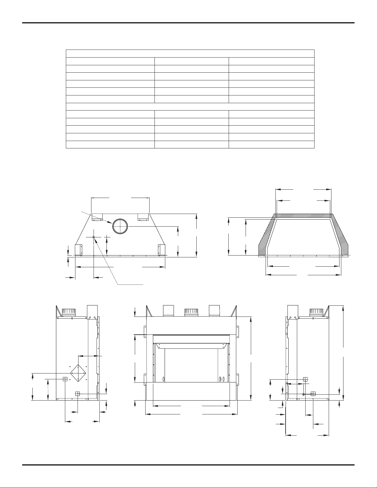
PRODUCT SPECIFICATION
6 7/8"
2 1/4"
7"
7"
Alternate Gas
Supply Inlet
13 1/4"
32 1/4"
* 27 1/2"
29"
* 13 3/4"
14 1/2"
* 20 3/8"
21 1/2"
2 1/2"
8 1/4"
11 3/4"
22 3/8"
For Use
With B-1
Vent Pipe
Only
16 3/4"
7 5/8"
10 5/8"
8 1/8"
10 1/2"
8 3/8"
2 1/2"
8 1/4"
5/8"
34 1/2"
35 3/8"
29 1/2"
18 1/4"
7"
7"
16 3/4"
36 1/2"
* WITH REFRACTORY
DIMENSIONS
HEARTH AREA
GAS RATING - NATURAL
BRT2032TEN BRT2332TEN AND BRT2532TEN
Max. Input Rating 15,000 Btu/Hr 25,000 Btu/Hr
Manifold Pressure 3.5" WC (0.87 kPa) 3.5" WC (0.87 kPa)
Minimum Supply Pressure 4.5" WC (1.12 kPa) 4.5" WC (1.12 kPa)
Maximum Supply Pressure 10.5" WC (2.66 kPa) 10.5" WC (2.66 kPa)
Orifice Size # 49 # 40
GAS RATING - PROPANE/LP
Max. Input Rating 15,000 Btu/Hr 25,000 Btu/Hr
Manifold Pressure 10" WC (2.49 kPa) 10" WC (2.49 kPa)
Minimum Supply Pressure 11" WC (2.74 kPa) 11" WC (2.74 kPa)
Maximum Supply Pressure 13" WC (3.23 kPa) 13" WC (3.23 kPa)
Orifice Size # 56 # 54
126746-01D
Figure 1 - Appliance Dimensions
Superiorfireplaces.US.com
5
Page 6
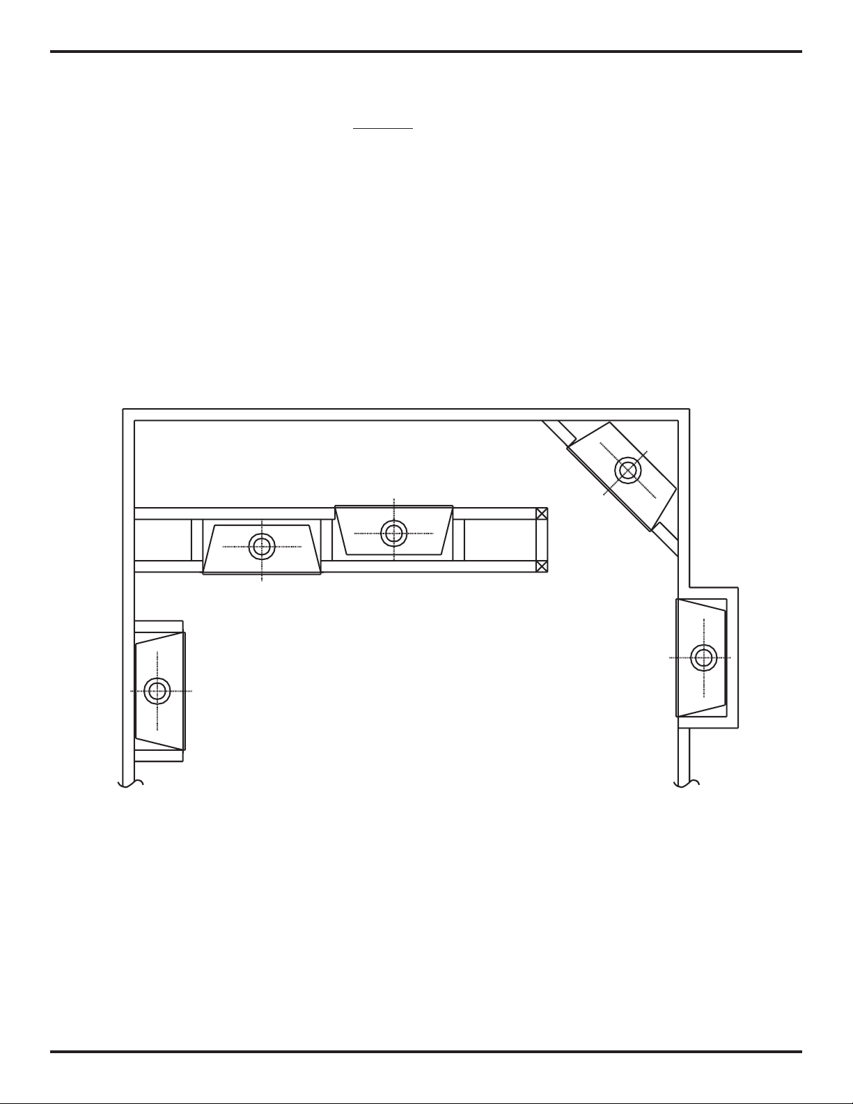
SELECTING LOCATION
INTERNAL WALL
INSTALLATION
CORNER
INSTALLATION
FULL
PROJECTION
INSTALLATION
FLUSH
INSTALLATION
To determine the safest and most efficient location for your appliance,
you must take into consideration the following guidelines:
1. The location must allow for proper clearances (see Clearances,
page 7).
2. Consider a location where heat output would not be affected by
drafts, air conditioning ducts, windows, or doors.
3. A location that avoids the cutting of joists or roof rafters will make
installation easier. Figure 2 shows a plan view of a few common
locations.
Flush installations are recommended where living space is limited or
at a premium, and since the space required to enclose the appliance
would be located beyond an outside wall, this would also reduce the
cutting of joists, roof rafters, and such. Check local codes for any
restrictions.
Projected installations can extend any distance into the room. A projection may be ideal for a new addition on an existing, finished wall.
Corner installations make use of space that may not normally be
used and provides a wider and more efficient range for radiant heat
transference.
Internal wall installations provide a discreet option for room separation and can also be ideal as an addition to an existing wall.
6
Figure 2 - Possible Locations for Installing Fireplace
Superiorfireplaces.US.com
126746-01D
Page 7
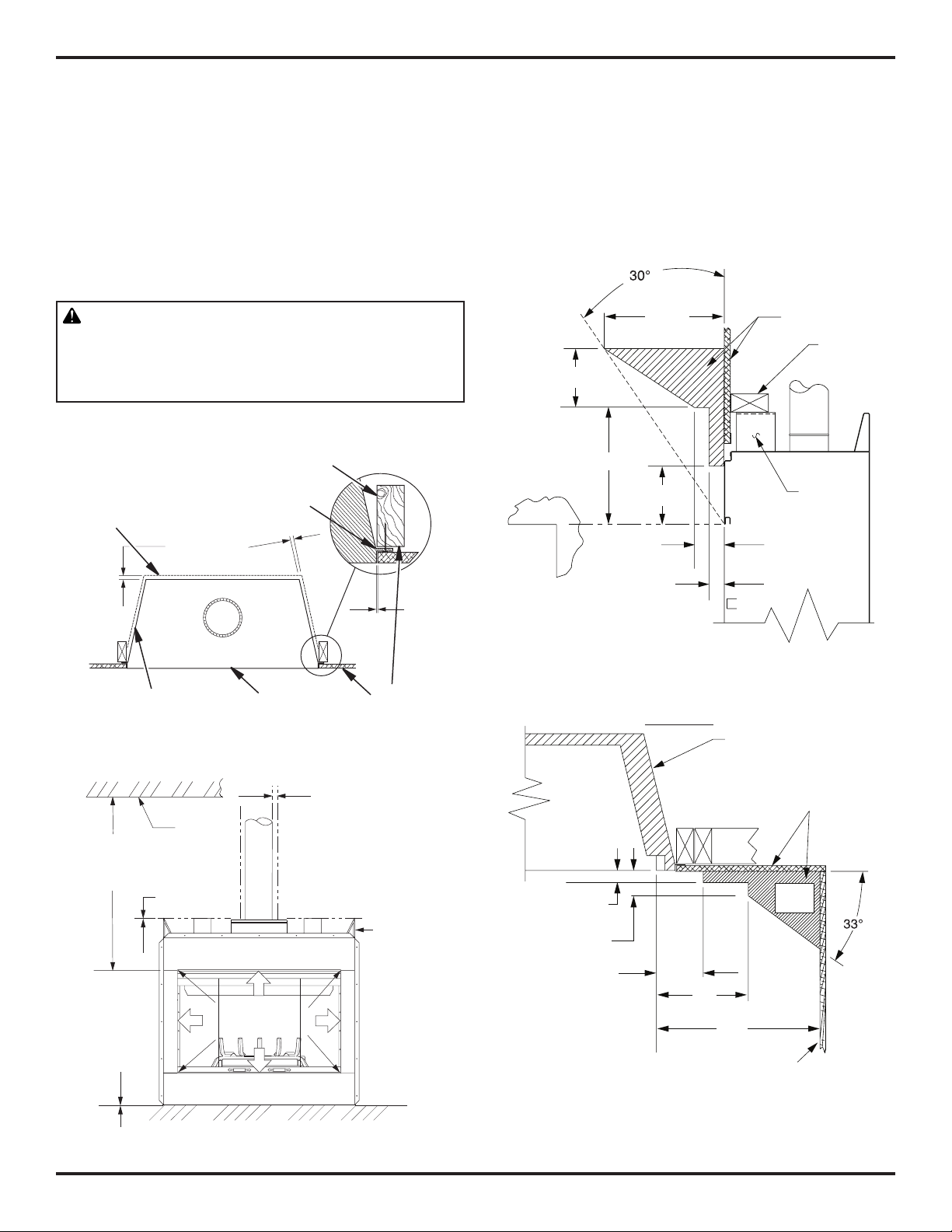
PRE-INSTALLATION PREPARATION
0 cm/
po
0 cm/po
Clearance
*
*
**
42" (10.67 cm)
Min. Clearance
from Opening to
Ceiling
0" Clearance
Ceiling
1" (2.5 cm) Min.
Clearance to
"B" Vent's Outer Pipe
Required
Air Spaces
are Indicated
with an "
*
".
Do Not
Pack with
Insulation or
Any Other
Material
DO NOT BLOCK
OR OBSTRUCT
OPENINGS
0" Clearance
to Wood or
Noncombustible
Flooring
Spacer
3" (7.6 cm)
1
1
/2"
(3.8 cm) Max.
8" (20.3 cm)
6" (15.2 cm)
13" (33 cm)
12"
(22.9 cm)
Combustible
Materials
Header
1 1/2" (3.8 cm)
Max.
3" (7.6 cm)
Max.
6" (15.2 cm)
Max.
9"
(22.86 cm)
12"
(30.48 cm)
Outer Surround
Combustible
Material May
Be Used
TOP VIEW
SAFE
ZONE
Perpendicular
Wall
CLEARANCES
Minimum clearances to combustibles are:
Ceiling 40" min.
Top of Spacers 0" min.
Back and Sides of Outer Surround 0" min.
Drywall to Sides of Front Face (Nailing Flanges) 0" min.
“B” Vent Surfaces 1" min.
Ceiling to Opening 42" min.
Floor 0" min.
Perpendicular Wall See Figure 6
CAUTION: Do not block required air spaces with
insulation or any other material. Do not obstruct effective opening of appliance with any type of facing
material.
2 x 4 Stud
Nailing
Back
Flange
MANTEL CLEARANCES AND WALL DETAILS
A combustible mantle shelf maybe installed a maximum 12" (22.9
cm) from the wall. Figures 5 and 6 show the minimum allowable
distances from various combustible mantle components in relation
to the fireplace opening.
Left Side Surround
126746-01D
Front Face
Figure 3 - Minimum Clearances (Top View)
Figure 4 - Minimum Clearances (Front View)
Figure 5 - Mantel Clearances - Side View (Cross Section)
Drywall
Superiorfireplaces.US.com
Figure 6 - Side Clearances - Top View (Cross Section)
7
Page 8
PRE-INSTALLATION PREPARATION Continued
16 1/8"
34
3
/4"
36
5
/8"
16 3/4"
12"
39
3
/8"
55
5
/8"
34
1
/2"
16"
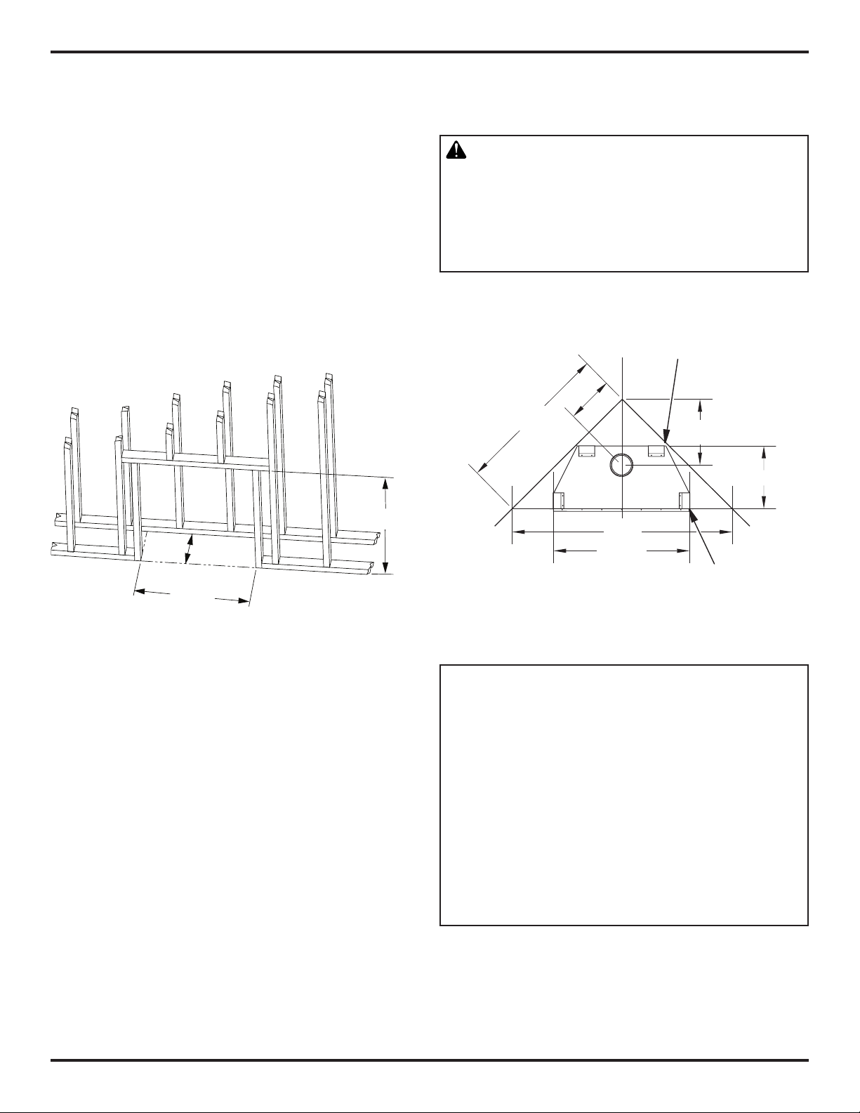
FRAMING
1. Frame appliance enclosure as illustrated in Figures 7 and 8.
Note: If a wall covering is used to line the enclosure, then all
measurements must be from the surface of the covering.
2. Place the appliance into the framing and secure it.
Note: If appliance is to be raised above floor level, a platform
must be built to support the appliance.
3. Install the supply line to the appliance using a 1/2" NPT black iron
gas line terminating 2 5/16" above the bottom of the appliance. The
gas line may be installed from either side or from the rear of the
appliance (see Figure 15, page 13).
4. Feed flexible gas line through one of three gas line conduit sleeves
and repack insulation to cover any openings. Prepare the incoming gas line with Teflon tape or pipe joint compound and hookup
incoming gas line to flexible gas line.
Note: If 1/2" NPT black iron pipe does not mate with fitting at
the end of flexible gas line, remove fitting and replace with a 37
degree flare 3/4"-12, 1/2" NPT (female) fitting.
WARNING: When finishing appliance, do not
overlap combustible material onto the black front
face. Brick, tile, or other noncombustible materials
may be applied to the face provided that any gap is
between the material used and the face is caulked
with a noncombustible caulking.
These Dimensions Allow for a 3/4"
Clearance at Sides and Back of
Fireplace. 0" Clearance is Permitted
Figure 7 - Rough Opening for Installing in Wall
3/4" Clearance Not Required
at Nailing Flanges
Figure 8 - Corner Installation Guidelines
IMPORTANT NOTICE
NFPA 54 defines minimum space requirements for
the installation of this appliance.
This fireplace must be installed in an unconfined
space with a minimum of 50 cubic feet per 1,000
BTUs of gas output. Therefore 36” models require
2,650 cubic feet, 42” models require 3,100 cubic
feet and 50” models require 3,300 cubic feet. If the
space you wish to install the fireplace does not meet
these requirements NFPA 54 details several actions
that may be taken.
8
Superiorfireplaces.US.com
126746-01D
Page 9

REQUIREMENTS FOR THE COMMONWEALTH OF MASSACHUSETTS
For all side wall horizontally vented gas fueled equipment installed
in every dwelling, building or structure used in whole or in part for
residential purposes, including those owned or operated by the
Commonwealth and where the side wall exhaust vent termination
is less than seven (7) feet above finished grade in the area of the
venting, including but not limited to decks and porches, the following
requirements shall be satisfied:
INSTALLATION OF CARBON MONOXIDE DETECTORS
At the time of installation of the side wall horizontal vented gas fueled equipment, the installing plumber or gas fitter shall observe that
a hard wired carbon monoxide detector with an alarm and battery
backup is installed on the floor level where the gas equipment is to be
installed. In addition, the installing plumber or gas fitter shall observe
that a battery operated or hard wired carbon monoxide detector with
an alarm is installed on each additional level of the dwelling, building
or structure served by the side wall horizontal vented gas fueled equipment. It shall be the responsibility of the property owner to secure
the services of qualified licensed professionals for the installation of
hard wired carbon monoxide detectors.
In the event that the side wall horizontally vented gas fueled equipment is installed in a crawl space or an attic, the hard wired carbon
monoxide detector with alarm and battery back-up may be installed
on the next adjacent floor level.
In the event that the requirements of this subdivision can not be
met at the time of completion of installation, the owner shall have
aperiodofthirty(30)daystocomplywiththeaboverequirements;
provided, however, that during said thirty (30) day period, a battery
operated carbon monoxide detector with an alarm shall be installed.
Approved Carbon Monoxide Detectors
Each carbon monoxide detector as required in accordance with
the above provisions shall comply with NFPA 720 and be ANSI/UL
2034 listed and IAS certified.
SIGNAGE
A metal or plastic identification plate shall be permanently mounted
to the exterior of the building at a minimum height of eight (8) feet
above grade directly in line with the exhaust vent terminal for the
horizontally vented gas fueled heating appliance or equipment. The
sign shall read, in print size no less than 1/2" in size, "GAS VENT
DIRECTLY BELOW. KEEP CLEAR OF ALL OBSTRUCTIONS".
INSPECTION
The state or local gas inspector of the side wall horizontally vented
gas fueled equipment shall not approve the installation unless, upon
inspection, the inspector observes carbon monoxide detectors and
signage installed in accordance with the provisions of 248 CMR
5.08(2)(a) 1 through 4.
EXEMPTIONS: The following equipment is exempt from 248 CMR
5.08(2)(a) 1 through 4:
• The equipmentlisted in Chapter 10 entitled"Equipment Not
Required To Be Vented" in the most current edition of NFPA 54
asadoptedbytheBoard;and
• ProductApprovedsidewallhorizontallyventedgasfueledequip-
ment installed in a room or structure separate from the dwelling,
building or structure used in whole or in part for residential
purposes.
MANUFACTURER REQUIREMENTS
Gas Equipment Venting System Provided
When the manufacturer of Product Approved side wall horizontally
vented gas equipment provides a venting system design or venting
system components with the equipment, the instructions provided
by the manufacturer for installation of the equipment and the venting system shall include:
• Detailedinstructionsfortheinstallationoftheventingsystem
designortheventingsystemcomponents;and
• Acompletepartslistfortheventingsystemdesignorventing
system.
Gas Equipment Venting System Not Provided
When the manufacturer of a Product Approved side wall horizontally
vented gas fueled equipment does not provide the parts for venting
the flue gases, but identifies "special venting systems", the following
requirements shall be satisfied by the manufacturer:
•
The referenced "special venting system" instructions shall be in-
cludedwiththeapplianceorequipmentinstallationinstructions;
and
• The"specialventingsystems"shallbeProductApprovedbythe
Board, and the instructions for that system shall include a parts
list and detailed installation instructions.
A copy of all installation instructions for all Product Approved side
wall horizontally vented gas fueled equipment, all venting instructions, all parts lists for venting instructions, and/or all venting
design instructions shall remain with the appliance or equipment
at the completion of the installation.
126746-01D
Superiorfireplaces.US.com
9
Page 10
VENTING INSTALLATION
Listed Vent Cap
A B-type venting system must be connected to the appliance for
venting to the outside of the building.
IHP defines installation standards of this product. Third party products must be installed to their specific standards.
Standing codes requirements concerning B-type vent installations
may vary within your state, province or local codes jurisdiction.
Therefore, it is recommended that you check with your local building codes for specific requirements or in absence of local codes,
follow Section 7.0 of the current National Fuel Gas Code NFPA No.
54/ANSI Z223.1.
This gas appliance must be vented to the outdoors only and may not
be terminated into an attic space or into a chimney flue servicing a
solid fuel burning appliance.
This appliance may be vented through a manufactured chimney
system or a masonry chimney using a B-vent adapter or a chimney
liner system if all are listed, inspected and approved by local codes
and/or building authorities.
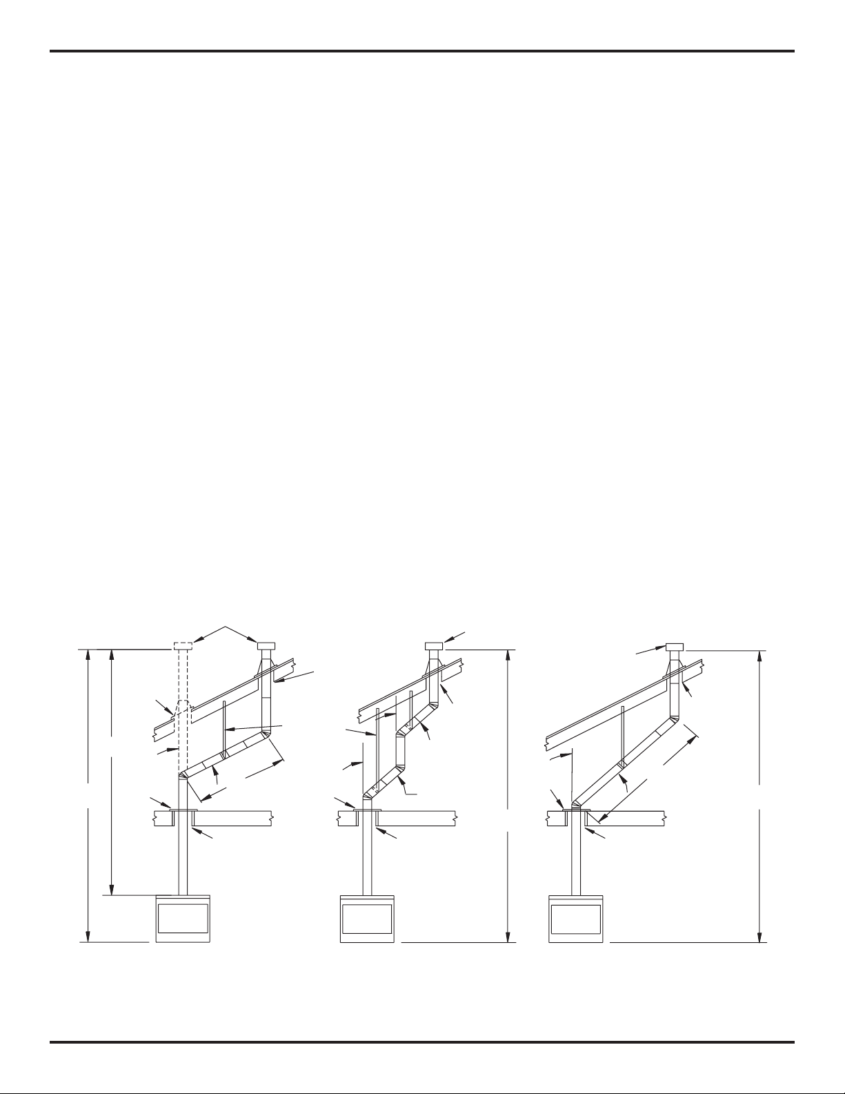
The examples shown in Figure 9, are typical of most B-vent installations and code practices.
Example 1 shows the minimum allowable system height and lateral
offset for a 60° or greater inclination. Code specifies that offsets at
60° or greater are considered horizontal and must follow the 75%
rule for lateral to total vertical system height. Codes also allows only
one offset in the total system when at 60° or greater. The total vertical
height in this example represents the minimum height of 8 feet and
therefore the allowable lateral is 6 feet when the 75% rule applies. If
the lateral length must exceed 75% then the system must be sized
in accordance with the Category I venting tables.
Example 2 shows a multiple offset each at 45° of inclination. Multiple
offsets are permitted if they do not exceed 45° of inclination. The
total lengths of the two offsets are not required to meet the 75%
allowable rule.
Example 3 shows a single offset at 45° of inclination and therefore the
lateral length at 10 feet of offset does not have to meet the 75% rule.
In each case the offsets must be supported and firestops must be
positioned wherever the vent must pass through a subfloor, ceiling
joist or an attic overhang. The vent pipe must terminate vertically
into a listed type vent cap and extend a sufficient height through an
approved roof flashing, roof jack or a roof thimble. At all points the
listed clearances must be maintained.
Vent terminations must be located in accordance with height and
proximity rules of NFPA No. 54. These rules apply to vents at 12"
diameter or less and require a minimum height in accordance with
the roof pitch and a minimum of 8 feet distance from a vertical wall
or obstruction (see Figure 10, page 11).
If venting horizontally through a side wall becomes necessary, a listed
thimble (38FST recommended) approved for use with B-type vent
must be used. Check with your local codes before venting through
a side wall.
12' Min.
Maintain
Listed
Clearance
8'
Position
Firestop
EXAMPLE 1
60°
Maintain
Listed
Clearance
Listed
Maintain
Listed
Clearance
Support
Each
Lateral
At Least
Every
45°
6 Feet
6'
Position
45°
Firestop
Maintain
Listed
Clearance
EXAMPLE 2
Figure 9 - Typical B-Vent Configuration
Vent Cap
Maintain
Listed
Clearance
12' Min.
Position
Firestop
Listed
Vent Cap
Maintain
Listed
Clearance
45°
10'
12' Min.
Maintain
Listed
Clearance
EXAMPLE 3
10
Superiorfireplaces.US.com
126746-01D
Page 11

VENTING INSTALLATION Continued
Lowest
Discharge
Opening
Listed
Vent Cap
8 Ft. Min.
Roof Pitch x/12
Listed Clearance
12
x
Listed
Gas
Vent
H (Min)
Height
From Roof
CHECKING FOR PROPER VENTING
After completing and checking the electrical, gas and vent connections, follow the lighting instructions and allow the main burner to
run for approximately 5 minutes. Hold a lit match or cigarette near
top edge of fireplace opening and play it along entire length of the
opening (see Figure 11). Proper venting should tend to draw flame
or smoke into appliance. Improper venting or escaping of spillage
of burned gas, is indicated when match flickers or goes out. Smoke
from a cigarette will also tend to disperse away from the appliance.
If appliance is found to be improperly venting, shut it off and notify
your installer or a qualified service agency to inspect venting system.
Roof Pitch H (Min.) Ft. m
Flat to 6/12 1.0 0.30
6/12 to 7/12 1.25 0.38
Over 7/12 to 8/12 1.5 0.46
Over 8/12 to 9/12 2.0 0.61
Over 9/12 to 10/12 2.5 0.76
Over 10/12 to 11/12 3.25 0.99
Over 11/12 to 12/12 4.0 1.22
Over 12/12 to 14/12 5.0 1.52
Over 14/12 to 16/12
Over 16/12 to 18/12 7.0 2.13
Over 18/12 to 20/12 7.5 2.27
Over 20/12 to 21/12 8.0 2.44
6.0 1.83
Figure 10 - B-Vent Terminations
some codes areas allow the use of existing B-type vent systems if
the system is at or above the recommended diameter of the flue.
The flue connection must be made using listed B-type connectors
and the existing system must be code inspected for damage and
proper installation.
It is not recommended that this appliance be common vented with an
existing gas burning appliance. However, if it becomes necessary to
common vent this appliance, the venting system must be sized and
configured in accordance with the common venting guides Appendix
G of the current National Fuel Gas Code NFPA No. 54/ANSI Z223.1.
Note: Before connecting this appliance to an existing vent system or
a common venting system consult with your local architect, planner,
or building official.
WARNING: This appliance must be properly connected to a system and must not be connected to a
chimney flue servicing a separate solid fuel burning
appliance.
NOTICE: This appliance is equipped with a vent safety
shutoff switch which will shut down appliance in case
of a venting problem. Do not bypass vent safety switch.
If appliance should shut down, contact a qualified
installer, service agency, or your gas supplier to have
vent inspected before operating.
Check area along entire
top edge of replace
opening. Smoke or
ame should be drawn
into appliance opening.
Figure 11 - Checking for Spillage
126746-01D
Superiorfireplaces.US.com
11
Page 12

FIREPLACE INSTALLATION
WALL SWITCH INSTALLATION
The installation of a wall switch allows you to activate the gas control
valve and turn the fireplace on and off. The wall switch is to be connected to the incoming 120 volt regular household wiring that supplies the electricity to the fireplace. Refer to Wiring Diagram, page 29.
OPTIONAL REMOTE CONTROL INSTALLATION (MODEL WRC)
Note: If using optional wireless hand-held remote control, wall switch
must be in ON position to be operational. The remote control then
becomes the switching mechanism for fireplace operation.
1. Remove front refractory access panel by lifting up and angling
out of firebox opening (see Figure 12).
2. WRC model receiver does not require a battery. Receiver can
be installed by first plugging short extension cord into fireplace
receptacle. Plug receiver unit into extension cord. Finally, plug
ignition module plug into receiver unit (see Figure 13).
3. Activate remote handset battery by removing insulating tab
on back of handset (see Figure 13A). Battery is included preinstalled.
4. Once battery is activated, unit is ready to use.
5. Replace front refractory access panel
Battery Cover
12 Volt Battery
Back of
Handset
Pull to Remove
Insulation Tab
Figure 13A - Installing Battery into Back of Handset
GAS LINE HOOK-UP
WARNING: Gas line hookup should be done by your
gas supplier or a qualified service person.
WARNING: Before you proceed, make sure your
gas supply is OFF.
Figure 12 - Removing Front Refractory Access Panel
(BRT2532TEN Model Shown)
Fireplace
Receptacle
Remote
Control
Receiver
The appliance and it’s individual shutoff valve must be disconnected
from the gas supply piping system during any pressure testing of
gas supply piping system at test pressures in excess of 1/2 psi (3.5
kPa). Appliance must be isolated from gas supply piping system
by closing its individual manual shutoff valve during any pressure
testing of gas supply piping system at test pressures equal to or less
than 1/2 psi (3.5 kPa).
A manual shutoff valve has been included in the appliance’s gas supply system. You may consider installing an extra gas shutoff valve
outside the appliance’s enclosure (check with local codes) where
it can be accessed more conveniently with a key through a wall as
shown in Figure 14, page 13.
In conformance with local codes, route a 1/2" NPT gas line towards
appliance coming in from any of the 3 directions shown in Figure 15.
CAUTION: Do not kink flexible gas line.
Extension
Cord
Ignition Module
Plug
Figure 13 - Installing the WRC Remote Receiver
12
Superiorfireplaces.US.com
126746-01D
Page 13

FIREPLACE INSTALLATION Continued
83/8"
10
5
/8"
1/2" NPT Incoming
Black Iron Gas Line
Flexible
Gas Line
(1 Provided)
Can Be
Extended Out
Either Side
7"
7"
Alternate Gas Supply
Through Sub-Floor
3" Min.
(7.6 cm)
Side Wall
Of Appliance
IHP recommends that a black iron gas line be routed from the gas
source, through a sediment trap (shown in Figure 16), and into appliance. Once connected through appliance, a flexible gas line may
be used for ease of installation to gas control valve (see Figure 17).
Typical Exterior
Shutoff Valve
Wall Gas Shutoff
Installation
Key
Extension
Figure 14 - Manual Shutoff Valve Installation
Incoming
1/2" Gas Line
Permitted by
Sediment
Local Codes
Trap (Not
Supplied)
Figure 16 - Sediment Trap
Before connecting the black iron gas line to the inside of the appliance
a sediment trap must be included outside the appliance between the
gas line and the gas shutoff valve. It must extend down 3" beyond
the center of the pipe. Prepare incoming black iron gas line with
Teflon tape or pipe joint compound (Check with local building codes).
CAUTION: Compounds used on threaded joints of
gas piping shall be resistant to the action of Liquefied
Petroleum (LP or propane), and should be applied
lightly to ensure excess sealant does not enter the
gas line. Sealant should not be used on a flare fitting
Figure 15 - Routing Incoming Gas Line
Equipment
Shutoff Valve
WARNING: All gas piping and connections must
be tested for leaks after the installation is completed.
After ensuring that the gas valve is on, apply a noncorrosive leak detection solution to all connections
and joints. If bubbles appear, leaks can be detected
and corrected.
Do not use an open flame for leak testing and do not
operate any appliance if a leak is detected.
Complete your gas installation by connecting incoming gas line
with flexible gas line. Secure tightly with wrench but DO NOT
OVERTIGHTEN.
Red Surface Indicates For
Propane/LP Use Only
Flexible Gas Line
Do NOT Kink
126746-01D
Note:
1) Wire Connections Not Shown for Clarity
2) * 1/8" NPT Plugged Tapping
1/2" NPT Incoming
Gas Line
Figure 17 - Connecting Flexible Gas Line to Electronic Valve
Inlet Pressure Tap
Superiorfireplaces.US.com
Outlet Pressure Tap
13
Page 14

GRATE PLACEMENT
0.5"
0.5"
FIREPLACE INSTALLATION Continued
Ember Material
Vermiculite (Pan Material)
The grate must be placed in the burner pan so that the back grate fingers (BRT2332TEN/BRT2532TEN) or pins (BRT2032TEN) fit into the
notches on back of burner pan and front legs fit inside burner pan as
shown in Figure 18.
Pins
Pins
Front
Leg
Notches
BRT2032TEN (Back)
Back Grate Fingers
Burner Pan
Back Grate
Fingers
Front
Leg
Notches
BRT2332TEN/
Burner Pan
BRT2532TEN (Back)
Figure 18 - Placing Grate into Burner Pan
EMBER AND PAN MATERIAL PLACEMENT
1. Open the bag(s) of vermiculite and fill the entire burner pan
until the burner tube is completely covered (see Figure 19).
2. Smooth the pan material just even with edges of the burner pan.
3. Remove the ember material from the bag and flatten small
amounts into quarter size pieces and lay on top of the surface of
the pan material (see Figure 20).
4. Place just enough to cover the entire surface and leave about a
1/2" gap under the lower grate members to allow air to flow (see
Figure 21).
Grate
Figure 20 - Ember Material on Surface of Pan Material
(Vermiculite) (BRT2332TEN/BRT2532TEN Models Shown)
Grate
Burner Pan
Figure 21 - Pan and Ember Material Clearances (BRT2332TEN/
BRT2532TEN Models Shown)
LOG PLACEMENT FOR BRT2032TEN MODEL
1. Place front log onto front of grate sliding log all the way forward
against grate fingers (see Figure 22).
2. Insert pegs on bottom of rear log into holes in rear of grate (see
Figure 22).
3. Place top right log into notches on left side of front and rear (see
Figure 23, page 15).
4. Place top left log into notches on right side of front and rear (see
Figure 23, page 15).
Pan and Ember Material
Burner Pan
NOTICE: Do not put lava rock inside the burner pan or
around the air mixer fitting. Placing lava rock inside
the burner pan or blocking the openings of the propane/
LP air-mixer could cause performance problems.
Front Log
Rear Log
Grate
Vermiculite
(Pan Material)
Figure 19 - Fill Entire Burner Pan with Vermiculite
(BRT2332TEN/BRT2332TEN Models Shown)
14
Burner Pan
Superiorfireplaces.US.com
Figure 22 - Installing Front and Rear Logs
126746-01D
Page 15

Top Left
Log
FIREPLACE INSTALLATION Continued
Top
Right
Log
Front
Left Log
Rear Log
Figure 23 - Installing Top Left and Right Logs
LOG PLACEMENT FOR BRT2332TEN
AND BRT2532TEN MODELS
1. Place rear log onto grate making sure notches rest over grate
(see Figure 24).
2. Place front right log onto front right side of grate with back of
log fitting into notch on right front of rear log (see Figure 24).
3. Rest front of front left log between first two grate fingers on left
of grate assembly and rear into notch on left front of rear log (see
Figure 25).
4. Place top of log 4 into notch on log 1. Rest log 4 on the center
of grate as shown in Figure 26.
5. Place top of log 5 into notch on top right of log 1 (see Figure 26).
Rest log 5 between two middle grate fingers as shown in Figure 27.
To enhance the look of the hearth you may optionally place the lava
rock provided around the front and sides of the burner.
NOTICE: Do not put lava rock inside the burner pan or
around the air mixer fitting. Placing lava rock inside
the burner pan or blocking the openings of the propane/
LP air-mixer could cause performance problems.
Figure 25 - Installing Log 3
Top Log
Top Y-Log
Front Left
Log
Rear Log
126746-01D
Rear
Log
Front
Right Log
Figure 24 - Installing Logs 1 and 2
Superiorfireplaces.US.com
Figure 26 - Installing Logs 4 and 5
Figure 27 - Logs Installed
15
Page 16

FIREPLACE INSTALLATION Continued
COMBUSTION AIR KIT MODEL AK4 (OPTIONAL)
The outside air kit may be installed on the left side of the fireplace
only. The vent can be installed through the outside wall or a ventilated
crawl space. The handle to operate the damper door for the outside
air inlet will be located inside the left “screen pocket” of the firebox
(see Figure 28). Pull the handle to open or push to close.
CAUTION: Air inlet ducts are not to terminate in
attic space.
Screen
Pocket
INSTALLING OPTIONAL GLASS DOOR ACCESSORY
CAUTION: Use only glass doors certified for use
with this appliance.
Note: Assistance with installation may be needed as glass doors
are heavy.
These B-vent fireplaces are approved for use with optional bi-fold glass
doors (see Accessories, page 23). The glass panels may be ordered
and installed anytime after the fireplace installation is complete.
Follow these steps to install left and right panels:
1. With handle at the bottom, completely fold panel on its hinges.
2. With handle facing center of firebox opening, insert lower pivot pin on
glass door panel into hole in pivot plate on bottom edge of fireplace
opening (see Figure 30).
3. Keeping folded door tilted, slide upper two pins into the guide
track found under upper facial edge of firebox opening.
4. Tilt door assembly fully vertical until outer pivot pin snaps into
mounting hole in upper spring clip (see Figure 30).
5. Once top and bottom pins are secured, unfold door into closed
position.
6. Repeat process for opposite door assembly.
Air Kit
Handle
Figure 28 - Air Kit Handle Location
APPLIANCE ENCLOSURE
Before finishing enclosure around appliance, inspect all joints around
outer surround. Any gaps between nailing flanges and framing should
be sealed with noncombustible insulation or caulking (see Figure 29).
If appliance is mounted on a raised platform, it must be a continuous
surface and not on blocks without a solid surface. This will prevent
the entry of cold air by means of conduction through the total bottom of the appliance.
Side
Side
Framing
Framing
Caulk Here
Figure 29 - Sealing Between Appliance and Framing
Pack Insulation
Slide Top Pin Into
Spring Clip
Door Track
Insert Pin Into
Spring Clip
Insert Bottom
Pivot Pin
Into Pivot
Plate and
Swing Door
Into Vertical
Position
Pivot
Plate
Figure 30 - Installing Optional Glass Door
7. To adjust doors, slide them partially open. Using a screwdriver,
loosen the hold-down screws in spring clip (see Figure 31, page
17) and pivot plate.
8. Close both doors until evenly joined at the middle and note gap
at outer edges of face.
9. Reopen one door at a time and retighten upper and lower holddown screws.
10. Repeat process until both doors are evenly joined, spaced and
working freely.
16
Superiorfireplaces.US.com
126746-01D
Page 17

FIREPLACE INSTALLATION Continued
CAUTION: Glass panels become very hot while
the appliance is operating. Do not attempt to adjust
or clean glass doors until appliance has fully cooled.
Spring Clip
Side
Front
Face
Partially
Opened
Door
Figure 31 - Adjusting Glass Doors
Hold-Down
Screw
Doors may be removed for replacement or cleaning as follows:
1. Partially open door and press up on the upper spring clip with a
screw driver until outer top pivot pin is free of clip.
2. Fully fold frame assembly and slide upper edge toward center of
firebox opening until guide pins are free of frame rail (see Figure
32).
CAUTION: Always operate appliance with doors
either fully opened or fully closed. Operating appliance with doors partially open can result in
improper venting of flue products.
Fold Bi-Fold Door
After Releasing
Spring Clip and
Slide Door Out of
Upper Track
Press Spring Clip
to Release Pivot
Pin
Spring
Clip
WARNING: Do not slam or strike doors. Damage
can result in a hazardous condition.
WARNING: Discontinue use of the appliance imme-
diately if doors are damaged and contact a qualified
installer for repair. Only doors certified with the appliance shall be used.
Remove
Bottom
Pin From
Pivot Plate
While
Sliding
Door Out
of the
Upper
Track
Pivot Plate
Figure 32 - Removing Glass Doors
126746-01D
Superiorfireplaces.US.com
17
Page 18

OPERATION
FOR YOUR SAFETY
READ BEFORE LIGHTING
WARNING: If you do not follow these instructions
exactly, a fire or explosion may result causing property
damage, personal injury or loss of life.
A. This appliance has a pilot that is equipped with an ignition
device which automatically lights the pilot. Do not light the
pilot by hand.
B. BEFORE LIGHTING smell all around the appliance area for gas.
Be sure to smell next to the floor because some gas is heavier
than air and will settle on the floor.
WHAT TO DO IF YOU SMELL GAS
•Donottrytolightanyappliance.
•Donottouchanyelectricswitch;donotuseanyphoneinyour
building.
•Immediatelycallyourgassupplierfromaneighbor’sphone.
Follow the gas supplier’s instructions.
•Ifyoucannotreachyourgassupplier,calltheredepartment.
C. Use only your hand to push in or turn the gas control knob. Never
use tools. If the knob will not push in or turn by hand, don’t try
to repair it, call a qualified service technician or gas supplier.
Force or attempted repair may result in a fire or explosion.
D. Do not use this appliance if any part has been under water.
Immediately call a qualified service technician to inspect the
appliance and to replace any part of the control system and any
gas control which has been under water.
LIGHTING
INSTRUCTIONS
NOTICE: During initial operation of new fireplace,
burning logs will give off a paper-burning smell.
Orange flame will also be present. Open damper or
window to vent smell. This will only last a few hours.
1. STOP! Read the safety information in column 1.
2. Turn wall switch (if installed) to the OFF position.
3. Turn off all electrical power to the appliance.
4. Place damper in full open position.
5. Fully open glass doors if installed.
6. Remove front refractory brick access panel.
7. Turn equipment shutoff valve clockwise to the OFF position (see Figure 33). Do not force.
8. Wait five (5) minutes to clear out any gas. Then smell for gas,
including near the floor. If you smell gas, STOP! Follow “B” in
the safety information, column 1. If you don’t smell gas go to
the next step.
9. Turn equipment shutoff valve counterclockwise to the
ON position. Do not force.
10. Replace front refractory brick access panel.
11. Fully close glass doors if installed
12. Turn on all electric power to fireplace.
13. Turn wall switch to the ON position.
14. Visually locate pilot. Ignitor should begin to spark and main
burner should ignite once flame appears at pilot.
• If lighting appliance for the first time each season, it may
take several attempts before supply gas can reach pilot
and main burner.
• If appliance will not stay lit after several attempts, follow
instructions in To Turn Off Gas To Appliance, and call your
service technician or gas supplier.
Adjustment
Equipment
Screw
Shutoff Valve
Figure 33 - Turning Equipment Shutoff Valve to the OFF Position
18
Superiorfireplaces.US.com
126746-01D
Page 19

OPERATION Continued
TO TURN OFF GAS
TO APPLIANCE
1. Turn off wall switch (if installed).
2. Turn off all electric power to appliance if service is to be performed.
3. Fully open glass doors if installed.
4. Remove front hearth brick and control access panel.
5. Turn equipment shutoff valve clockwise to OFF. Do not
force.
6. Replace front refractory brick access panel.
7. Fully close glass doors if installed.
Sensing
Pilot
Rod
Burner
Ignitor
OPTIONAL HAND-HELD
REMOTE OPERATION
Note: The WRC receiver and hand-held remote control kit must be
purchased separately (see Accessories, page 23). Follow installation
instructions included with the remote control.
1. Turn equipment shutoff valve to ON position. You can now turn
burner on and off with hand-held remote unit.
IMPORTANT: Be sure to press ON/OFF buttons on hand-held
remote control unit for up to 3 seconds to assure proper operation.
2. Press ON/OFF button to turn the burner on and off.
Figure 34 - Pilot
126746-01D
Superiorfireplaces.US.com
19
Page 20

INSPECTING BURNERS
PILOT ASSEMBLY
The pilot assembly is factory preset for the proper flame. Alterations
may have occurred during shipping and handling. The pilot is located
on the back right hand side of burner.
The flame must envelope 1/4" of top of the ignitor/sensor and
grounding stem.
If your pilot assembly does not meet these requirements:
• Turn adjustment screw marked PILOT clockwise to decrease or
counterclockwise to increase flame to proper size (see Figure
35). Do not remove adjustment screw.
• see Troubleshooting, page 21
Pilot
Burner
Sensing
Rod
Ignitor/
Sensor
BURNER FLAME PATTERN
Burnerameswillbesteady;notliftingoroating.Flamesshould
go up through the middle of log set. Flames should not "spill" to the
edges of the pan or sides of the log set.
Figure 36 shows a typical flame pattern. If burner flame pattern differs from that described:
• turnapplianceoff(seeTo Turn Off Gas to Appliance, page 19)
• seeTroubleshooting, page 21
(BRT2032TEN) Model
Figure 35 - Correct Pilot Flame Pattern
CLEANING AND MAINTENANCE
WARNING: Installation and repair should be done
by a qualified service person. The appliance should
be inspected before each use and at least annually
by a qualified service person. More frequent cleaning
may be required due to excessive lint from carpeting,
bedding material, pet hair, etc. It is imperative that
the control compartments, burners, and circulating
air system be kept clean.
WARNING: Logs can be hot. Handle only when
cool.
WARNING: Turn off gas and electrical power before
servicing appliance.
(BRT2332TEN/BRT2532TEN) Models
Figure 36 - Typical Flame Pattern
PILOT AND BURNER
• Remove logs and ember materialbefore cleaning burner and
replace when cleaning is complete.
• Burner andcontrols should becleaned with compressedair to
remove dust, dirt, or lint.
• Use a vacuumcleaner or small, soft bristledbrush to remove
excess dust, dirt, or lint.
LOGS
• Ifyouremovelogsforcleaning,refertologplacementinformation
on page 14 to properly replace logs.
• Useavacuumcleanertoremoveanycarbonbuilduponlogs.
• Replacelog(s)ifbroken.SeeReplacement Parts, page 23.
• Replaceember materialperiodically asneeded. See Replacement
Parts, page 23.
20
Superiorfireplaces.US.com
126746-01D
Page 21

TROUBLESHOOTING
Note: Before troubleshooting the system, make sure the gas shutoff valve is ON.
The two most common causes of a malfunctioning gas appliance are:
1. Loose wiring connections
2. Construction debris clogging the pilot and/or gas control valve filter
OBSERVED PROBLEM
Ignitor will not spark or pilot will not light
Pilot will not stay lit
POSSIBLE CAUSE
1. No gas supply, or shutoff valve is OFF
2. Air in gas line
3. Construction debris clogging pilot orifice
4. Low gas pressure
5. Kinked pilot line
6. Control valve knob is not opening
7. No power to unit or the ignition module or
power transformer is bad
8. Vent damper not fully open
1. Loose wiring on thermopile to regulator
valve.
2. If valve knob and wall switch are in the ON
position, probable defective regulator valve
3. Vent damper not fully open
REMEDY
1. Check to see if you have gas supply and that
equipment shutoff valve is opened
2. Repeat lighting procedure several times to
purge all air out of lines. If after repeated
attempts appliance does not light, call for
qualified service and repair.
3. Remove debris and dirt, inspect and clean
any other possible obstructions
4. Contact your gas supplier to check pressure
5. Have a qualified technician replace pilot line
6. Replace control valve (Refer to Replacement
Parts, page 23)
7. Check that main power is on and that all wire
connections are made correctly to ignition
model (see Wiring Diagram, page 29). Check
for 24 VAC at secondary side of transformer.
If 24 VAC is present, and module does not
operate, have module replaced, otherwise
have transformer replaced
8. Open vent damper until fully locked in the
OPEN position
1. Check wiring connections. Refer to wiring
diagram shown in page 29
2. Have a qualified technician replace valve
3. Open Vent damper until fully locked in the
OPEN position
126746-01D
Superiorfireplaces.US.com
21
Page 22

TROUBLESHOOTING Continued
WARNING: If you smell gas
•Shutoffgassupply.
•Donottrytolightanyappliance.
•Donottouchanyelectricalswitch;donotuseanyphoneinyourbuilding.
•Immediatelycallyourgassupplierfromaneighbor’sphone.Followthegassupplier’sinstructions.
•Ifyoucannotreachyourgassupplier,calltheredepartment.
IMPORTANT: Operating fireplace where impurities in air exist may create odors. Cleaning supplies, paint, paint remover, cigarette smoke,
cements and glues, new carpet or textiles, etc., create fumes. These fumes may mix with combustion air and create odors.
OBSERVED PROBLEM
No gas to burner, although wall switch and valve
are set to the ON position
Frequent pilot outage
Fireplace produces a clicking/ticking noise after
burner is lit or shut off
Fireplace produces unwanted odors
Gas odor even when control knob is in OFF
position
Gas odor during combustion
POSSIBLE CAUSE
1. Wall switch wires defective or too long
2. Thermopile not generating sufficient voltage
1. Pilot flame may be too low, causing safety
pilot to “drop out”
2. Improper venting or excessive blockage
1. Metal expanding while heating or contracting
while cooling
1. Fireplace burning vapors from paint, hair
spray, glues, etc. (See IMPORTANT statement above)
2. For propane/LP gas, low fuel supply
3. Gas leak. See Warning statement at top of
page
1. Gas leak. See Warning statement at top of
page
2. Control valve defective
1. Foreign matter between control valve and
burner
2. Gas leak. See Warning statement at top of
page
REMEDY
1. Check electrical connections
2. See Pilot will not stay lit, column 1, page 21
1. Clean and adjust pilot flame for maximum
flame impingement on thermopile
2. Have the vent system inspected, including
the termination cap. Remove any restriction
or obstruction
1. This is normal with most fireplaces. If noise
is excessive, contact qualified service person
1. Ventilate room. Stop using odor causing
products while fireplace is running
2. Contact local propane/LP supplier
3. Locate and correct all leaks (see Gas Line
Hook-Up, page 12)
1. Locate and correct all leaks (see Gas Line
Hook-Up, page 12)
2. Replace control valve
1. Take apart gas tubing and remove foreign
matter
2. Locate and correct all leaks (see Gas Line
Hook-Up, page 12)
Dark residue on logs or inside of fireplace
22
1. Improper log placement
2. Air holes at burner inlet blocked
3. Burner flame holes blocked
4. Improper venting or excessive blockage
5. Excessive amounts of embers and pan material
Superiorfireplaces.US.com
1. Properly locate logs
2. Clean out air holes at burner inlets. Periodically repeat as needed
3. Remove blockage or replace burner
4. Have the vent system inspected, including
the termination cap. Remove any restrictions
or obstruction
5. Clear excess embers until a minimum gap
of 1/2" remains under the grate
126746-01D
Page 23

REPLACEMENT PARTS
Note: Use only original replacement parts. This will protect your
warranty coverage for parts replaced under warranty.
Contact authorized dealers of this product. If they can’t supply original
replacement part(s), call IHP at 1-800-655-2008.
When calling, have ready:
• yourname
• youraddress
• modelandserialnumbersofyourreplace
• howreplacewasmalfunctioning
• purchasedate
Usually, we will ask you to return the part to the factory.
SERVICE HINTS
When Gas Pressure Is Too Low
• pilotwillnotstaylit
• burnerwillhavedelayedignition
• replacewillnotproducespeciedheat
• propane/LPgassupplymaybelowifusingpropane/LPgas
You may feel your gas pressure is too low. If so, contact your local
gas supplier.
ACCESSORIES
Purchase these accessories from your local dealer. If they can not
supply these accessories call IHP at 1-800-655-2008 for information. You can also write to the address listed on the back page of
this manual.
AIR KIT - AK4
Optional kit helps offset the negative pressure often existing in today's
tightly constructed homes. Negative pressure may occur then other
appliances in the home draw on air, possibly leading to poor operation,
soot, or spillage.
REMOTE CONTROL KIT - WRC
Standard On/Off Electronic Remote Control Kit.
GWMS2 - Wall Mount ON/OFF Switch
32" EXTRUDED ALUMINUM BI-FOLD GLASS DOORS
BD32 - Black Finish
BD32B - Brushed Brass Finish
BD32P - Platinum Finish
TECHNICAL SERVICE
You may have further questions about installation, operation, or
troubleshooting. If so, contact IHP at 1-800-655-2008. When calling
please have your model and serial numbers of your fireplace ready.
You can also visit our web site at
IHP.US.com.
32" FIXED GLASS DOOR KIT
FD32 - Black Finish
FD32B - Brushed Brass Finish
FD32P - Platinum Finish
BRICK LINER KIT
BL32 - Refractory Standard Brick Liner Kit
PERIMETER TRIM
PT32 - Black
PT32B - Brushed Brass
PT32P - Platinum
PROPANE/LP GAS CONVERSION KIT
PCBE-324 - 4" B-Vent Electronic Fireplace
PCBE-325 - 5" B-Vent Electronic Fireplace
126746-01D
Superiorfireplaces.US.com
23
Page 24

MODEL BRT2032TEN
33
43
41
15
19
24
14
30
26
29
3
14
12
13
23
35
16
31
32
32
38
39
40
40
4
34
21
20
22
5
5
37
42
1
1
36
28
25
9
2
7
17
11
6
27
10
11
24-3
18
18
24-9
NG
LP
24-8
24-8
24-4
24-9
24-12
24-10
24-11
24-6
24-2
24-5
24-1
24-7
CATALOG NO. MODEL
F0852 BRT2032TEN
PARTS
Superiorfireplaces.US.com
24
126746-01D
Page 25

PARTS
MODEL BRT2032TEN
This list contains replaceable parts used in your fireplace. When ordering parts, follow the instructions listed under Replacement Parts on
page 23 of this manual.
WARNING: Contact an IHP dealer to obtain any of these parts. Never use substitute materials not approved
by IHP. Use of non-approved parts can result in poor performance and safety hazards.
CATALOG
MODEL
NO.
F0852 BRT2032TEN
KEY NO. PART NO. DESCRIPTION QTY.
1 108769-03 Extension Deflector 2
2 109098-01 Wire Assembly Electric Harness 1
3 108864-01 Strain Relief 1/2" Bushing 1
4 108425-01 Air Rod Retainer 1
5 20280 Top Spacer 4
6 108863-01 24" Supply Connect Plug 1
7 14253 Flexible Supply Line with Shutoff Valve 1
8 108411-01 Air Separator 1
9 11186 Screw, #8-32 x 1" PPH Zinc. 2
10 11109 Screw, #8-32 x 1/2" PPH Zinc. 2
11 11201 Nut, #8-32 Hex Zinc. 4
12 108428-03 Bottom Front Refractory, Std. Brick 1
13 108426-03 Bottom Rear Refractory, Std. Brick 1
14 106683-01 Firebox Support Leg 2
15 24353 Box Assembly 1
16 108701-01 Screen Rod 2
17 14301 Ignition Module 1
18 11165 Screw, #10x5/8 Mod. Tr. Blk. Ox 2
19 106703-02 Damper Door Assembly 1
20 108416-01 4" Collar 1
21 108412-01 Smoke Deflector 1
22 108415-01 Starter Pipe Collar 1
23 109797-01 Grate Assembly 1
24 109107-02 Burner Assembly 1
24-1 107742-03 Burner Pan 1
24-2 109794-01 Burner Tube 1
24-3 107748-01 Burner Bracket 1
24-4 107985-01 Pilot Shield 1
24-5 109793-01 Divider Pan 1
24-6 11209 Nut, #10-24 1
24-7 11147 Screw, #10-24x1/2 1
24-8 901066-01 Brass Air Mixer (NG) 1
24-9 901064-12 Injector (NG) 1
24-10
24-11
24-12
25 14569 Electronic Gas Valve (NG) 1
26 107741-02 Valve Bracket 1
27 14129 Transformer 1
28 108368-01 3/8" Flex Line 1
29 11107 Screw, #10-32 x 1/4 PPH 4
30 108005-05 Wire Harness 1
31 11418 Push-On Nut 2
32 108440-01 Screen 2
33 14123 Strain Relief 1
34 14574 Limit Switch 1
35 22912 Draft Diverter 1
36 106827-01 4" Gasket 1
37 20042 Air Kit Cover 1
38 20088 Door Stop 1
39 20089 Pivot Clip 2
40 20090 Spring Clip 2
41 21171 Gas Knockout Cover 4
42 108652-01 Gas Conduit Assembly, Left 1
43 108654-01 Gas Conduit Assembly, Right 1
901066-02 Brass Air Mixer (LP) 1
901065-11 Injector (LP) 1
108866-01 Pilot (Natural Gas) 1
108867-01 Pilot Orifice (LP) 1
11102 Screw, #8-32x3/8 2
14570 Electronic Gas Valve (LP) 1
PARTS AVAILABLE NOT SHOWN
901155-01 Vermiculite Bag 1
901156-01 Pan Material 1
901157-01 Lava Rock 1
126746-01D
Superiorfireplaces.US.com
25
Page 26

MODELS BRT2332TEN AND BRT2532TEN
33
43
41
15
19
24
14
30
26
29
17
14
12
13
24-3
18
18
24-9
NG
LP
24-8
24-8
24-4
24-9
24-12
24-10
24-11
24-6
24-2
24-5
24-1
24-7
23
10
36
9
36
35
16
31
32
32
38
39
40
40
4
34
21
8
46
45
44
44
11
37
42
1
1
28
25
6
7
22
5
54
20
27
3
2
CATALOG NO. MODEL
F0854 BRT2332TEN
F0856 BRT2532TEN
PARTS
Superiorfireplaces.US.com
26
126746-01D
Page 27

PARTS
MODELS BRT2332TEN AND BRT2532TEN
This list contains replaceable parts used in your fireplace. When ordering parts, follow the instructions listed under Replacement Parts on
page 23 of this manual.
WARNING: Contact an IHP dealer to obtain any of these parts. Never use substitute materials not approved
by IHP. Use of non-approved parts can result in poor performance and safety hazards.
BRT2332TEN
KEY NO. PART NO. DESCRIPTION
1 108769-03 Extension Deflector • • 2
2 11201 Nut, #8-32 Hex Zinc. • • 2
3 11109 Screw, #8-32 x 1/2" PPH Zinc. • • 2
4 108425-01 Air Rod Retainer • • 1
5 14301 Ignition Module • • 1
6 11186 Screw, #8-32 x 1" PPH Zinc. • • 2
7 109098-01 Wire Assembly Electric Harness • • 1
8 108411-01 Air Separator • • 1
9 108434-01 Left Refractory, Std. Brick (B Models) • • 1
10 108432-01 Right Refractory, Std. Brick (B Models) • • 1
11 108430-01 Rear Refractory, Std. Brick (B Models) • • 1
12 108428-01 Bottom Front Refractory, Std. Brick • • 1
13 108426-01 Bottom Rear Refractory, Std. Brick • • 1
14 106683-01 Firebox Support Leg • • 2
15 24353 Box Assembly • • 1
16 108701-01 Screen Rod • • 2
17 108864-01 Strain Relief 1/2" Bushing • • 1
18 11165 Screw, #10 x 5/8 Mod. Tr. Blk. Ox • • 2
19 106703-02 Damper Door Assembly • • 1
20 108863-01 24" Supply Connect Plug • • 1
21 108412-01 Smoke Deflector • • 1
22 14253 Flexible Supply Line with Shutoff Valve • • 1
23 109040-01 Grate Assembly • • 1
24 108712-06 Burner Assembly • • 1
24-1 107742-03 Burner Pan • • 1
24-2 109037-01 Burner Tube • • 1
24-3 107748-01 Burner Bracket • • 1
24-4 107985-01 Pilot Shield • • 1
24-5 901681-01 Burner Clamp • • 1
24-6 11209 Nut, #10-24 • • 1
24-7 11147 Screw, #10-24 x 1/2 • • 1
24-8 901066-01 Brass Air Mixer (NG) • • 1
24-9 901064-11 Injector (NG) • • 1
24-10
24-11
24-12
25 14569 Electronic Gas Valve (NG) • • 1
26 107741-02 Valve Bracket • • 1
27 14129 Transformer • • 1
28 108368-01 3/8" Flex Line • • 1
29 11107 Screw, #10-32 x 1/4 PPH • • 4
30 108005-05 Wire Harness • • 1
31 11418 Push-On Nut • • 2
32 108440-01 Screen • • 2
33 14123 Strain Relief • • 1
34 14574 Limit Switch • • 1
35 22912 Draft Diverter • • 1
36 20027 Brick Liner Retainer • • 2
37 20042 Air Kit Cover • • 1
38 20088 Door Stop • • 1
39 20089 Pivot Clip • • 2
40 20090 Spring Clip • • 2
41 21171 Gas Knockout Cover • • 4
42 108652-01 Gas Conduit Assembly, Left • • 1
43 108654-01 Gas Conduit Assembly, Right • • 1
44 20280 Top Spacer • • 4
45 108415-01 Starter Pipe Collar • • 1
46 108417-01 5" Collar • • 1
901066-02 Brass Air Mixer (LP) • • 1
901065-09 Injector (LP) • • 1
108866-01 Pilot (NG) • • 1
108867-01 Pilot Orifice (LP) • • 1
11102 Screw, #8-32 x 3/8 • • 2
14570 Electronic Gas Valve (LP) • • 1
PARTS AVAILABLE NOT SHOWN
901155-01 Vermiculite Bag • • 1
901156-01 Pan Material • • 1
901157-01 Lava Rock • • 1
(F0854)
BRT2532TEN
(F0856) QTY.
126746-01D
Superiorfireplaces.US.com
27
Page 28

PARTS
1
4
2
3
LOG ASSEMBLY
This list contains replaceable parts used in your fireplace. When ordering parts, follow the instructions listed under Replacement Parts on
page 23 of this manual.
5
4
1
3
2
BRT2032TEN (F0852) MODEL BRT2332TEN (F0854) AND BRT2532TEN (F0856) MODELS
KEY NO. PART NO. DESCRIPTION QTY.
109109-01 Log Set
1 105958-05 Front Log 1
2 105960-05 Rear Log 1
3 901100-02 Top Right Log 1
4 901102-02 Top Left Log 1
KEY NO. PART NO. DESCRIPTION QTY.
109100-02 Log Set
1 109421-01 Rear Log 1
2 109420-01 Front Right Log 1
3 108723-01 Front Left Log 1
4 108722-01 Top Y-Log 1
5 108720-01 Top Log 1
28
Superiorfireplaces.US.com
126746-01D
Page 29

STEP DOWN
TRANSFORMER
VENT SAFETY
SHUTOFF
SWITCH
EV2
SUPPLY
INCOMING
MAIN GAS
EV1
TO
GAS LINE
BURNER
24V AC
120V AC
120V AC
INCOMING
OR BREAKER)
(FUSE BOX
OFF
ON
(SUPPLIED)
WALL SWITCH
GREEN
BLACK
WHITE
120v, 60Hz, 0.7A
ELECTRICAL RATING:
BLACK
WHITE
GREEN
OPTIONAL
REMOTE
CONTROL
PV
GND
PV/MV
TR
MV
TH
IGN
WIRING DIAGRAM
126746-01D
Superiorfireplaces.US.com
29
Page 30

NOTES
______________________________________________________
______________________________________________________
______________________________________________________
______________________________________________________
______________________________________________________
______________________________________________________
______________________________________________________
______________________________________________________
______________________________________________________
______________________________________________________
______________________________________________________
______________________________________________________
_____________________________________________________
______________________________________________________
______________________________________________________
______________________________________________________
______________________________________________________
______________________________________________________
______________________________________________________
______________________________________________________
______________________________________________________
______________________________________________________
______________________________________________________
______________________________________________________
______________________________________________________
_____________________________________________________
______________________________________________________
______________________________________________________
______________________________________________________
______________________________________________________
______________________________________________________
______________________________________________________
______________________________________________________
30
Superiorfireplaces.US.com
126746-01D
Page 31

Innovative Hearth Products
Superior™ Brand Gas Fireplaces, Stoves and Inserts
20 Year Limited Warranty
THE WARRANTY
Innovative Hearth Products ("IHP") 20 Year Limited Warranty warrants your Superior™ Brand gas fireplace, Stove or Insert ("Product") to be free from defects in materials
and workmanship at the time of manufacture. The Product body and firebox carry the 20 Year Limited Warranty. Ceramic glass carries the 20 Year Limited Warranty against
thermal breakage only. After installation, if covered components manufactured by IHP are found to be defective in materials or workmanship during the 20 Year Limited
Warranty period and while the Product remains at the site of the original installation, IHP will, at its option, repair or replace the covered components. If repair or replacement
is not commercially practical, IHP will, at its option, refund the purchase price or wholesale price of the IHP product, whichever is applicable. IHP will also pay IHP prevailing labor rates, as determined in its sole discretion, incurred in repairing or replacing such components for up to five years. THERE ARE EXCLUSIONS AND LIMITATIONS
to this 20 Year Limited Warranty as described herein.
COVERAGE COMMENCEMENT DATE
Warranty coverage begins on the date of installation. In the case of new home construction, warranty coverage begins on the date of first occupancy of the dwelling or six
months after the sale of the Product by an independent IHP dealer/distributor, whichever occurs earlier. The warranty shall commence no later than 24 months following
the date of product shipment from IHP, regardless of the installation or occupancy date.
EXCLUSIONS AND LIMITATIONS
This 20 Year Limited Warranty applies only if the Product is installed in the United States or Canada and only if operated and maintained in accordance with the printed
instructions accompanying the Product and in compliance with all applicable installation and building codes and good trade practices.
This warranty is non-transferable and extends to the original owner only. The Product must be purchased through a listed supplier of IHP and proof of purchase must be
provided. The Product body and firebox carry the 20 Year Limited Warranty from the date of installation. Vent components, trim components and paint are excluded from
this 20 Year Limited Warranty. The following do not carry the 20 Year Limited Warranty but are warranted as follows:
Burner – Repair or replacement for one year from the date of installation
Gas components – Repair or replacement for one year from the date of installation
Gaskets – Repair or replacement for one year from the date of installation
Logs – Replacement for one year from the date of installation against thermal breakage only
Optional blowers & remote controls – Repair or replacement for one year from the date of installation
Optional glass doors – Repair or replacement for 90 days from the date of installation
Tempered glass - Replacement for one year from the date of installation
Labor coverage – Prevailing IHP labor rates apply for the warranty period of the component
Parts not otherwise listed carry a 90 day warranty from the date of installation.
Whenever practicable, IHP will provide replacement parts, if available, for a period of 10 years from the last date of manufacture of the Product.
IHP will not be responsible for: (a) damages caused by normal wear and tear, accident, riot, fire, flood or acts of God; (b) damages caused by abuse, negligence, misuse, or
unauthorized alteration or repair of the Product affecting its stability or performance (The Product must be subjected to normal use. The Product is designed to burn either
natural or propane gas only. Burning conventional fuels such as wood, coal or any other solid fuel will cause damage to the Product, will produce excessive temperatures
and could result in a fire hazard.); (c) damages caused by failing to provide proper maintenance and service in accordance with the instructions provided with the Product;
(d) damages, repairs or inefficiency resulting from faulty installation or application of the Product.
IHP is not responsible for inadequate fireplace system draft caused by air conditioning and heating systems, mechanical ventilation systems, or general construction conditions which may generate negative pressure in the room in which the appliance is installed. Additionally IHP assumes no responsibility for drafting conditions caused by
venting configurations, adjoining trees or buildings, adverse wind conditions or unusual environmental factors and conditions that affect the operation of the unit.
This 20 Year Limited Warranty covers only parts and labor as provided herein. In no case shall IHP be responsible for materials, components or construction, which are not
manufactured or supplied by IHP or for the labor necessary to install, repair or remove such materials, components or construction. Additional utility bills incurred due to
any malfunction or defect in equipment are not covered by this warranty. All replacement or repair components will be shipped F.O.B. from the nearest stocking IHP factory.
LIMITATION ON LIABILITY
It is expressly agreed and understood that IHP’s sole obligation and the purchaser’s exclusive remedy under this warranty, under any other warranty, expressed or implied,
or in contract, tort or otherwise, shall be limited to replacement, repair, or refund, as specified herein.
In no event shall IHP be liable for any incidental or consequential damages caused by defects in the Product, whether such damage occurs or is discovered before or
after repair or replacement, and whether such damage is caused by IHP’s negligence. IHP has not made and does not make any representation or warranty of fitness for a
particular use or purpose, and there is no implied condition of fitness for a particular use or purpose.
IHP makes no expressed warranties except as stated in this 20 Year Limited Warranty. The duration of any implied warranty is limited to the duration of this expressed warranty.
No one is authorized to change this 20 Year Limited Warranty or to create for IHP any other obligation or liability in connection with the Product. Some states and provinces
do not allow the exclusion or limitation of incidental or consequential damages, so the above limitations or exclusions may not apply to you. The provisions of this 20 Year
Limited Warranty are in addition to and not a modification of or subtraction from any statutory warranties and other rights and remedies provided by law.
INVESTIGATION OF CLAIMS AGAINST WARRANTY
IHP reserves the right to investigate any and all claims against this 20 Year Limited Warranty and to decide, in its sole discretion, upon the method of settlement.
To receive the benefits and advantages described in this 20 Year Limited Warranty, the appliance must be installed and repaired by a licensed contractor approved by IHP.
Contact IHP at the address provided herein to obtain a listing of approved dealers/distributors. IHP shall in no event be responsible for any warranty work done by a
contractor that is not approved without first obtaining IHP's prior written consent.
HOW TO REGISTER A CLAIM AGAINST WARRANTY
In order for any claim under this warranty to be valid, you must contact the IHP dealer/distributor from which you purchased the product. If you cannot locate the dealer/
distributor, then you must notify IHP in writing. IHP must be notified of the claimed defect in writing within 90 days of the date of failure. Notices should be directed to the
IHP Warranty Department at 1508 Elm Hill Pike, Suite 108; Nashville, TN 37210 or visit our website at WWW.SUPERIORFIREPLACES.US.COM.
Printed in U.S.A. © 2013 Innovative Hearth Products LLC
126746-01D
P/N 900223-00, Rev. NC 12/2013
Superiorfireplaces.US.com
Innovative Hearth Products
31
1508 Elm Hill Pike, Suite 108 • Nashville, TN 37210
Page 32

Model (
located on product or identification tag
Serial No. (
located on product or identification tag
Date Purchased _______________________________
Keep receipt for warranty verification.
KEEP THIS WARRANTY
) ____________________________________
) _________________________________
IHP reserves the right to make changes at any time, without notice, in design, materials, specifications, prices and also to discontinue colors, styles and products. Consult your local distributor
for fireplace code information.
Printed in U.S.A. © 2013 IHP LLC
P/N 126746-01 Rev. D 10/2014.
1508 Elm Hill Pike, Suite 108
Nashville, TN 37210
1-800-655-2008
IHP.US.com
 Loading...