


MANUAL
User Manual for Sunways
Solar Inverters NT 2600, NT 4000 and
NT 6000

180 mm |
300 mm |
mm 510

List of Contents
1.0General information
1.1 |
Safety information |
83 |
General safety information |
|
|
|
84 |
Opening the unit |
|
1.2 |
Sunways Solar Inverters |
85 |
Scope of supply, inspecting the delivery |
|
|
NT 2600, NT 4000 and NT 6000 |
86 |
Integration into the PV system |
|
|
|
|
Design of the PV generator |
EN |
|
|
87 |
Standard components of a PV system |
|
|
|
88 |
Protection concept |
|
2.0Information on installation
2.1 |
Safety information |
90 |
Electrical safety |
|
|
|
Mechanical safety |
|
|
91 |
Information on cleaning |
2.2 |
Installation |
93 |
Requirements on the place of installation |
|
|
94 |
Electrical connection and cable entry |
|
|
95 |
Grid connection |
|
|
97 |
PV generator connection |
|
|
98 |
Important Information |
|
|
100 |
Communication connections |
79 |
|
102 |
Connecting the sensors |

2.3 Commissioning |
104 |
Switching the solar inverter on and off |
|
106 |
Configurations |
|
108 |
Structure and menu levels for configuration |
3.0Information on operation
3.1 |
Monitoring and diagnosis |
111 |
Display |
|
|
112 |
Data memory |
3.2 |
Sunways NT Monitor software |
113 |
General information |
|
|
114 |
Initialising the remote modem |
|
|
115 |
Connection and circuitry options |
|
|
120 |
Configuring the interface cables |
|
|
122 |
Sunways NT Monitor data acquisition |
|
|
123 |
Operation of Sunways NT Monitor |
3.3 |
Fault indications |
125 |
Screen displays |
3.4 |
Fault diagnosis |
127 |
Indications, causes and remedies |
3.5 |
Warranty terms and conditions |
130 |
Warranty period |
|
|
|
Terms and exclusion of liability for |
|
|
|
solar inverters |
80

4.0Appendix
4.1 |
Subject and abbreviation index |
133 |
Designation and description |
|
4.2 |
Function and information index |
135 |
Functional principle and explanations |
|
|
|
138 |
Block diagram |
|
|
|
140 |
Technical data |
|
|
|
144 |
TYCO SOLARLOK connectors |
|
|
|
146 |
Conformity and safety declarations |
|
|
|
150 |
General exclusion of liability, rights, |
EN |
|
|
|
registered trademarks
81

1.0 General information
82

1.1Safety information
The User Manual contains safety hints. These are identified by a triangle with an exclamation mark.
!
General safety information
All safety hints contained in this section and throughout the User Manual must
be complied with at all times to guarantee the user's safety. The described product must not be operated if any mechanical or electrical components are defective.
Before commissioning the system, we
strongly advise you to carefully read and EN heed the instructions! Non-compliance
can have serious consequences, for example damage to the unit or other property or physical injuries with possible loss of life.
The solar inverter must be installed by a trained, qualified electrician. The electrician must be approved by the competent electricity board (EB).
The relevant tasks to be carried out are identified by an additional adjacent symbol in the respective chapter headings.
83

Opening the unit
! Before opening the cabinet, the unit must always be disconnected from the grid and from the PV generator.
The unit continues to conduct a hazardous voltage internally and at the connection sockets for ca. five minutes after disconnecting from the PV generator. The energy storage capacitors are only fully discharged after this period.
After disconnecting the unit from the grid and from the PV generator, you must wait at least five minutes before opening the unit.
84

1.2 Sunways Solar Inverters NT 2600, |
Inspecting the delivery |
|
NT 4000 and NT 6000 |
|
|
|
The condition of our products is checked |
|
Scope of supply |
prior to delivery. Although our products |
|
|
are carefully packed in recyclable packing, |
|
· Sunways Solar Inverter in the NT series |
transportation damages can still occur. |
|
· Installation frame |
These are generally the transport compa- |
|
· Manual, setup, warranty card, CD-Rom |
ny's responsibility. |
|
with software |
|
|
· 2 pairs of TYCO SOLARLOK connectors |
Please inspect the delivered solar inverter |
|
|
thoroughly! |
EN |
|
If you discover any damage to the packing |
|
|
or the solar inverter, please inform the |
|
|
transport company immediately. Your |
|
|
specialist dealer will be glad to assist you |
|
|
if required. Any damages must always be |
|
|
reported to the transport company in wri- |
|
|
ting seven days after receipt of the goods |
|
|
at the latest. |
|
85

Integration of the solar inverter into the PV system
Design of the PV generator
The technical data of the selected PV generator must be within the specification of the solar inverter (see Technical Data). The Sunways NT Sundim design program for the PV generator may be helpful. Sunways NT Sundim is available on the enclosed CD or from our website, www.sunways.de.
Please take account of the following points before planning your system:
·Pay attention to the skyward alignment of the modules. You will obtain maximum yield in Central Europe with a module inclination of 30° to the horizontal and a direct southerly alignment of the generator field.
·The output of the cells decreases as the module temperature increases. Install your PV generator with adequate rear ventilation.
·Check your PV generator for soiling ca. every three years. This occurs particularly at the lower edge of the modules and forms a film, which even heavy rain cannot wash away. Decreases in yield can be prevented by cleaning with a wet cloth or a brush.
·Avoid shading of individual modules or solar cells in your system. This can result in heavy losses in yield.
86
Standard components of a PV system
Depending on the recommendations of your electrician, your PV system will consist of the following components:
Standard components of the PV system
PV |
|
SUNWAYS NT |
|
(1) |
PV generator switch |
EN |
|
|
(2) |
sensor |
|||
|
|
|
Irradiation sensor with |
|
||
|
|
|
|
|
integrated temperature |
|
PV |
(1) |
(3) |
(4) |
(3) |
Mains fuse |
|
|
||||||
(4) |
Energy meter |
|
||||
(2) |
|
|
PC |
Grid |
|
|
PV generator switch:
Designed as DC load break cut-out to cut off the PV generator from the solar inverter. Dimensioning: min. 800 V, ≥ 16 A
Grid connection:
3-phase (Feed-in: 1-phase; grid monitoring: 3-phase)
87

Protection concept |
The following parameters are monitored |
|
|
continuously and in parallel by the micro- |
|
|
controller and displayed on the screen: |
|
|
· AFI error (ground fault) |
|
|
· Overheating of the cooling element |
|
|
· |
DC overvoltage |
|
· |
AC undervoltage/overvoltage |
In the event of a fault, the conversion is immediately blocked and the grid relay disconnected.
In addition, the following protective devices are provided on both grid and PV generator side:
· Grid-side varistors
Protect the power semiconductors from high-energy, time-limited voltage spikes on the grid and provide for a reduction of energy in the throttle in the event of grid disconnection.
· Generator-side varistors
Thermally monitored varistors provide protection against atmospheric overvoltages (e.g. due to remote strikes during storms).
88

2.0Information on installation
89
2.1 Safety information |
Electrical safety |
Before opening the cabinet, the solar
! inverter must be disconnected from the grid and from the PV generator.
The solar inverter continues to conduct
a hazardous voltage internally and at the connection sockets for the PV generator for ca. five minutes after disconnecting from the PV generator. The energy storage capacitors are only fully discharged after this period.
After disconnecting the solar inverter from the grid and PV generator, you must wait at least five minutes before opening the solar inverter.
Mechanical safety
During installation, make sure that the cables or connection lines fitted to the solar inverter are securely laid and that suitable mechanical cable supports (cable ducts etc.) are used.
90

!
91
Information on cleaning |
|
Before cleaning, disconnect the system |
|
from the power grid by opening the grid |
|
breaker (main fuse) and open the DC |
|
switch on the PV generator, in order to |
|
exclude the danger of electric shocks. |
|
Use a soft, dry cloth to clean the system. |
|
Never use corrosive, solvent-containing |
|
or abrasive cleaners or polishes. |
EN |
|

2.2Installation
The solar inverter must be installed by a trained, qualified electrician. A special tool is
necessary for installation. Please read this chapter very carefully.
Warm
Air
mm 300
150 mm |
150 mm |
Cool
Air
mm 300
92

Requirements on the place of installation
· Mechanical bearing capacity
During installation please bear in mind that the solar inverter weighs 26 kg. The installation base must be firm and capable of continuously bearing the weight.
· Thermal interaction
The installation base must consist of flame-retardant material (e.g. no wood or plastic in the base; concrete and brickwork are suitable), as the heat sink emits temperatures up to max. 85°C.
A minimum distance of 300 mm must be maintained above and below the cabinet, and 150 mm on right and left from other units, cabinets, ceilings, cable ducts etc..
The solar inverter must be installed vertically, so as not to hinder adequate free convection.
Several solar inverters must not be installed on top of each other, so as to prevent reciprocal heating.
If installing the solar inverter in a switch box, ensure adequate heat dissipation.
The ambient temperature must not fall below or exceed –25°C or +40°C.
The solar inverter should not be exposed to direct solar irradiation, so as to protect it from unnecessary external heating.
· Protection from damp and foreign bodies |
EN |
|
The IP54 high protection class permits installation both inside and in roofed outdoor areas, but the solar inverter must not be exposed to direct rain.
Make sure that the solar inverter cannot be exposed to foreign bodies (deposits of dust and dirt).
93

Electrical connection and cable entry
!
For installation, please observe the instructions in the "Setup" leaflet!
– DC – DC +DC +DC
If the solar inverter is fixed to the installation frame, the electrical connection can be led through. The unit may only be opened by a qualified electrician. The cabinet cover must first be released and removed.
The following cable inlets are located on the underside:
RS 232, RS 485, |
|
Irradiation sensor with inte- |
|
grated temperature sensor |
AC wiring loom |
cable |
L1, L2, L3, N, PE |
Fig.: Inlets on the unit underside |
94 |

Grid connection
!
The grid connection of the solar inverter must have 5 wires (L1, L2, L3, PE, N). Cable cross-sections of 5 x 4 mm2 are recommended.
The solar inverter is connected to the supply grid via the circuit board terminals inside the unit.
As line safety element in the grid feed-in direction, we recommend a 3 x 25 A automatic cut-out. No consumption units must be connected to the feed line from the solar inverter to the automatic cut-out. The solar inverter only feeds in via terminal L1.
If several solar inverters are operated in parallel, the feed-in phase L1 of the unit
must be evenly distributed over grid EN phases L1, L2 and L3 (see figure below).
Three-phase grid connection distributed over three units
L1 N L2 L3 PE |
L1 N L2 L3 PE |
L1 N L2 L3 PE |
L1
L2
L3
N
PE
95
You must use adequately dimensioned cable cross-sections in order to avoid a considerable increase in the grid impedance between the domestic distribution and the solar inverter. The terminal range of the AC terminals is 0.5 to 6 mm2 for rigid cables and 0.5 to 10 mm2 for flexible cables. With a high grid impedance, i.e. with a long line or too small a crosssection, the voltage increases at the grid terminal during feed-in.
If the terminal voltage exceeds the permissible value, the solar inverter is disconnected from the grid.
Carefully perform the following steps:
·Check that there is no voltage before introducing the supply main into the unit.
·Lead the 5-core AC cable (outer diameter 9 – 17 mm) through the M25 threaded cable gland.
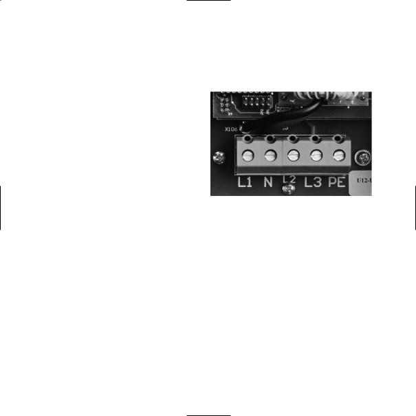
·Connect cables L1, L2, L3, PE and N to the relevant circuit board terminal with the help of a slot-head screwdriver (see figure below).
· Tighten the M25 screw connection, so that the cable cannot exert any mechanical force on the circuit board terminal.
96
PV generator connection
!
· Preparation
Execute the DC cabling according to your electrician's system dimensioning. Check each PV string for correct functioning
by performing a no-load voltage current and short-circuit current measurement.
To achieve the necessary protection against hazardous contact voltage during the installation of PV systems, the positive and negative conductors must be kept separate from the ground potential (PE).
Contactable, conductive parts of the PV generator (e.g. metal frame, supporting structure etc.) must be earthed (connected to PE).
Check that the generator is free from ground faults.
Make the electrical connection to the 97 solar inverter.
· Connection
The PV generator is connected via the externally accessible, shock-proof TYCO SOLARLOK connectors, which are enclosed with the delivery. The TYCO SOLARLOK connectors are designed for a cable crosssection of 4 mm2 and must be crimped (see data sheet and connector assembly with TYCO crimping tool on page 144).
Connect the two right DC female connectors |
EN |
with «+», the two left DC female connectors |
|
with «-» of the PV generator (see figure |
|
below). |
|

Important information
!
·The direct PV generator voltage is available internally after connecting the PV generator to the solar inverter via the DC connectors and switching on the PV generator switch!
·Please note that the input capacitors are still charged even after switching off the PV generator switch or removing the PV generator plug connection!
·After disconnecting the AC and DC side, the solar inverter still conducts voltage for up to ca. five minutes!
·Therefore, wait for at least five minutes until the internal voltage has dissipated. Then you can work on the terminals!
Please note the general safety information on pages 83 and 84!
98

·The DC voltage can be up to 750 V. The unit may only be opened by a qualified electrician!
·Always disconnect the PV generator side first by opening the PV generator switch, and then the grid connection by isolating the relevant mains fuse!
·If you do not have a PV generator switch
in your PV system, you must disconnect |
EN |
the grid connection first of all by isola- |
|
ting the relevant mains fuse. However, a |
|
«grid error» will be entered in the error |
|
memory of the solar inverter! |
|
·Disconnection of the PV generator by removing the TYCO SOLARLOK DC connectors must never be performed under load. In the event of non-compliance, the connectors could be damaged by a strong electric arc. In this case, the relevant connectors must be replaced!
99
 Loading...