


MANUAL
User Manual for
Sunways Solar Inverter NT 10000
200

SOLAR
INVERTERS
User Manual for
Sunways Solar Inverter NT 10000

Table of contents
1.0General Information
1.1 |
Safety Instructions |
91 |
General Safety Instructions |
|
|
|
92 |
Opening the Device |
|
1.2 |
Sunways Solar Inverter |
93 |
Scope of Delivery |
|
|
NT 10000 |
94 |
Integrating the Solar Inverter |
|
|
|
|
in the PV System |
GB |
|
|
96 |
Structure of NT 10000 |
|
|
|
98 |
Protection Concept |
|
2.0Installation Instructions
2.1 |
Safety Instructions |
101 |
Electrical Safety |
|
|
101 |
Mechanical Safety |
|
|
102 |
Cleaning Instructions |
2.2 |
Basic Settings |
103 |
Setting the Fixed Voltage Level |
|
|
104 |
Country Settings |
2.3 |
Installation |
107 |
Installation Site Requirements |
|
|
108 |
Mechanical Installation |
|
|
108 |
Electrical Connection and Cable Entry |
|
|
109 |
Grid Connection |
|
|
112 |
Connecting the PV Generator |
|
|
115 |
Communication Interfaces |
87

|
|
118 |
Connecting the Alarm Relay |
|
|
120 |
Connecting the Insolation and |
|
|
|
Temperature Sensor |
2.4 |
Commissioning the Solar Inverter |
122 |
Starting-Up and Shutting-Down the |
|
|
|
Solar Inverter |
2.5 |
Dismantling the Solar Inverter |
123 |
General Information |
3.0Operating Instructions
3.1 |
Operating the Display |
125 |
Menu Guide |
|
|
125 |
Navigating with the Arrow Keys |
|
|
125 |
Setting Values |
|
|
126 |
Menu Navigation Diagram |
3.2 |
Configuration of the Solar Inverter 128 |
Setting the RS485 address |
|
|
|
128 |
Setting the Date / Time |
|
|
128 |
Setting the Display Language |
|
|
128 |
Setting the LCD Contrast |
|
|
128 |
Setting the Total Yield |
3.3 |
3.3 Internal Data Memory |
129 |
General Information |
3.4 |
Sunways Monitor 2.0 Software |
130 |
General Information |
3.5 |
Sunways Portal and Sunways |
131 |
General Information |
|
Communicator |
|
|
88

3.6 |
Communication Link |
131 |
Modem Link |
|
|
|
132 |
Interface Cables |
|
|
|
132 |
Interface Transformer |
|
|
|
133 |
Linking and Interconnecting Possibilities |
|
3.7 |
Error Display |
139 |
Errors 001 to 036 |
|
3.8 |
Error Diagnosis |
144 |
Error, Causes and Remedies |
|
|
|
|
|
|
4.0 |
Appendix |
|
|
GB |
4.2 |
Tyco Solarlok Connectors |
154 |
Safety Instruction and Installation |
|
4.2 |
List of Special Terms and |
156 |
Designation and Description |
|
|
Abbreviations |
|
|
|
4.3 |
Technical Data NT 10000 |
158 |
Solar Inverter NT 10000 |
|
4.4 |
Conformity and Safety |
160 |
EU Low Voltage Directive 73/23/EEC |
|
|
Declarations |
161 |
EMC Directive 89/336/EEC, Including Changes |
|
|
|
|
91/263/EEC |
|
|
|
162 |
Safety Clearance / Certificate of Compliance |
|
|
|
|
(VDEW 4th edition 2001) |
|
4.5 |
Terms and Conditions of |
163 |
Duration of Guarantee, Conditions, |
|
|
Guarantee |
|
Exclusion of Liability |
|
4.6 |
General Exclusion of Liability |
165 |
Rights, Registered Trademarks |
|
89

1.0 General information |
Thank you for having chosen a Sunways |
|
Solar Inverter NT 10000! You have acquired |
|
a high-quality product with unique features |
|
and a top efficiency level. This Solar Inverter |
|
is designed in accordance with the proven |
|
HERIC® topology and therefore guarantees |
|
you a maximum energy yield. |
|
The Solar Inverter is equipped with three |
|
independent energy units which transform |
|
the energy of three separately connected |
|
PV generators into grid-compatible AC |
|
power and inject it in three phases. Thanks |
|
to the MPP multitracking process, PV gene- |
|
rators with various ratings can be connected |
|
to the same Solar Inverter with the |
|
NT 10000. |
|
In this user manual, you will find explana- |
|
tions on how to use the Sunways Solar |
|
Inverter NT 10000. It includes information |
|
on installation, commissioning, the functio- |
|
ning method, and system monitoring. |
90
1.1Safety Instructions
The user manual contains safety instructions. They are marked by a triangle with an exclamation mark.
!
General Safety Instructions
All safety instructions contained in this section as well as in the entire user manual must be observed to ensure the safety of the user. The described product may not be operated if any mechanical or electrical component is defect.
Prior to commissioning the PV system, we
strongly recommend reading and observing GB the manual and the instructions carefully! Non-compliance may lead to serious con-
sequences such as damage to the device, damage to other assets, personal injury, or fatal accidents.
The Solar Inverter may only be installed by a trained and qualified electrician.
It must be approved by the power supply company in charge. In the chapter headings, the due steps are additionally marked by the adjacent symbol.
91

! |
Opening the Device |
Prior to opening the housing, always |
|
|
disconnect the device from the grid and |
|
the PV generator. |
|
After having been disconnected from the |
|
PV generator, there is still lethal voltage |
|
inside the device and at the PV generator |
|
hubs for approximately five minutes. It |
|
takes that long for the energy-storing |
|
capacitors to fully discharge. |
|
After having disconnected the device |
|
from the grid and the PV generator, wait |
|
at least five minutes before opening the |
|
device. |
92

1.2 Sunways Solar Inverter NT 10000
Scope of Delivery
·Sunways Solar Inverter NT 10000
·assembly frame
·user manual, setup, guarantee card, CD ROM with software
·3 pairs of Tyco Solarlok connectors
Checking the Consignment
Prior to shipment, our products are checked to make sure they are in a perfect condition. They are carefully packaged in recyclable materials. Nevertheless, damage may occur during transportation which is normally the fault of the forwarding company.
Please check the delivered Solar Inverter |
|
carefully! |
GB |
|
Should you notice any damage to the packaging or to the Solar Inverter, please notify the forwarding company immediately. If required, your specialist dealer will be glad to support you. If a damage report is needed, it must be filed with the forwarding company no later than seven days after receipt of the consignment.
93

Integrating the Solar Inverter
in the PV System
Rating of the PV Generator
The technical data of the selected PV generator must be compatible with the specification of the Solar Inverter (see Technical Data). An incompatible rating may reduce the yield or destroy the device. The rating program Sunways NT Sundim can help you select the correct PV generator rating. You will find Sunways NT Sundim on the enclosed CD ROM or on our homepage www.sunways.de.
Prior to planning your system, please take the following considerations into account:
·Mind the orientation of the modules. In Central Europe, you will gain a maximum yield if the module has a horizontal angle of 30° and the PV generator field points directly towards the south.
·The warmer the module gets, the smaller the output of the cells will be. Therefore, make sure your PV generator has sufficient back ventilation when you install it.
·Check your PV generator for contamination approximately every three years. Contamination mostly occurs on the lower edge of the module; it forms a veil that is not even washed off by heavy rain. A loss of yield can be prevented by cleaning the modules with a wet cloth or a brush.
·Make sure none of the modules or solar cells of your system are in the shade. That may lead to a significant loss of yield.
·The NT 10000 has three internal energy units that are supplied by three independent PV generators. The NT 10000 is based on the «MPP multitracking» principle; i. e. each inlet has its own MPP controller.
94
Standard Components of a PV System
Depending on the recommendations of
your PV planner, your PV system is made
up of the following components:
Standard components of the PV system
PV |
(1) |
PV |
(1) |
PV |
(1) |
INVERTER
|
|
(1) |
PV generator switch |
|
|
(2) |
Insolation sensor with |
|
|
|
integrated temperature |
|
|
|
probe |
|
|
(3) |
Grid fuse |
(3) |
(4) |
(4) |
Power meter |
(2) |
PC |
GRID |
|
|
|
|
The PV generator switch is designed as a DC switch-disconnector and is made for disconnecting the PV generator from the Solar Inverter.
Rating: at least 900 V, ≥16 A
Since the NT 10000 is supplied by three independent PV generators, the DC main switches must also be independently of each other. It can be designed as a packettype switch, for example.
Grid connection:
The NT 10000 is connected to the grid in three phases. Each phase is internally controlled and monitored independently of the others.
95

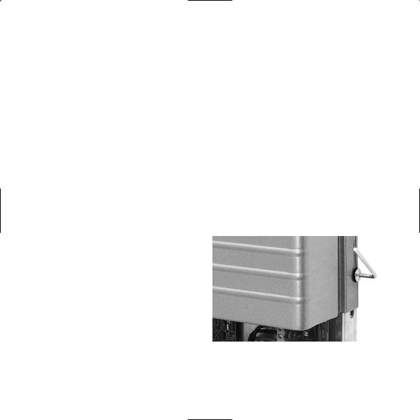
Structure of NT 10000 |
|
The Solar Inverter NT 10000 is made up of |
|
|
|
three energy units that are controlled |
|
|
|
independently of each other. Each energy |
|
|
|
unit has its own DC inlet. |
|
|
|
|
|
Energy Unit |
DC Inlet |
Control Circuit Board |
AC Grid Connection |
Energy unit 1 |
DC inlet 1 |
Control circuit board 1 |
Phase L1 |
Energy unit 2 |
DC inlet 2 |
Control circuit board 2 |
Phase L2 |
Energy unit 3 |
DC inlet 3 |
Control circuit board 3 |
Phase L3 |
|
|
|
|
|
|
The following illustration shows the con- |
|
|
|
nection of the DC inlet and the layout of |
|
|
|
the energy unit: |
|
96
Energy unit 3
Energy unit 2
Energy unit 1
Underside of the device
Solar Inverter NT 10000
Control circuit board 3
Control circuit board 2
Control circuit board 1
L1 

L2 

Interface circuit board L3 

N
PE
++ +
(1) |
(2) |
(3) |
DC inlet |
AC grid |
|
connection |
|||||
– |
– |
– |
|
||
|
|
97

Protection Concept
The micro controller continuously and simultaneously monitors and displays the following parameters. Numbers 1 to 3 refer to the energy units 1 to 3:
The numbering 1 to 3 refers respectively to the performance unit 1 to 3:
Error No. |
Description |
Error |
Description |
001 |
DC overvoltage 1 |
No.021 |
Insulation fault 2 |
002 |
DC overvoltage 2 |
022 |
Insulation fault 3 |
003 |
DC overvoltage 3 |
023 |
DC injection 1 |
004 |
Frequency fault 1 |
024 |
DC injection 2 |
005 |
Frequency fault 2 |
025 |
DC injection 3 |
006 |
Frequency fault 3 |
026 |
Isolated operation |
007 |
Overheating of heat sink 1 |
027 |
Grid overvoltage 3-phase |
008 |
Overheating of heat sink 2 |
028 |
Surge fault 1 |
009 |
Overheating of heat sink 3 |
029 |
Surge fault 2 |
010 |
Grid undervoltage 1-phase 1 |
030 |
Surge fault 3 |
011 |
Grid undervoltage 1-phase 2 |
031 |
Grid voltage 10 minutes mean value |
012 |
Grid undervoltage 1-phase 3 |
|
> 10 percent Unominal 1 |
013 |
Grid overvoltage 1-phase 1 |
032 |
Grid voltage 10 minutes mean value |
014 |
Grid overvoltage 1-phase 2 |
|
> 10 percent Unominal 2 |
015 |
Grid overvoltage 1-phase 3 |
033 |
Grid voltage 10 minutes mean value |
016 |
Grid undervoltage 3-phase |
|
> 10 percent Unominal 3 |
017 |
AFI fault 1 |
034 |
Control circuit board 1 fault |
018 |
AFI fault 2 |
035 |
Control circuit board 2 fault |
019 |
AFI fault 3 |
036 |
Control circuit board 3 fault |
020 |
Insulation fault 1 |
038 |
Back-up battery empty |
|
|
|
|
98

In case of an error, the current injection
is immediately stopped, and the grid relay is triggered which disconnects the Solar Inverter from the grid.
In addition, there are the following protection devices on the grid side and on the PV generator side:
· Varistors on the grid side
They protect the power semiconductors GB in case of high-power, temporary voltage
peaks in the grid, and they discharge the throttle in case of disconnection from the grid.
·Varistors on the PV generator side Varistors offer protection from atmospheric overvoltage (e. g. caused by remote lightning strikes).
99

2.0Installation Instructions
100

2.1Safety Instructions
!
Electrical Safety
Prior to opening the housing, disconnect the Solar Inverter from the electricity of the grid and the PV generator.
After disconnection from the PV generator and the grid, there is still lethal voltage inside the Solar Inverter and at the
PV generator hubs for approximately five
minutes. It takes that long for the energy- GB storing capacitors to fully discharge.
After having disconnected the Solar Inverter from the grid and the PV generator, wait at least five minutes before opening the Solar Inverter.
Mechanical Safety
During assembly, make sure the cables or connecting lines attached to the Solar Inverter are installed safely and suitable mechanical cable retaining devices (e. g. cable channels) are used.
101

! |
Cleaning Instructions |
Prior to cleaning your PV modules, always |
|
|
disconnect the PV system from the power |
|
grid by opening the grid disconnecting |
|
device (main fuse), and open the DC circuit |
|
breaker on the PV generator to prevent |
|
the risk of an electric shock. |
|
Use a dry, soft cloth to clean your PV |
|
modules. Never use caustic, solvent-based, |
|
or scouring cleaning agents or polish. |
|
Please observe the instructions of the |
|
PV module manufacturer. |
102
2.2Basic Settings
Setting the Fixed Voltage Level
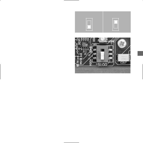
Your Sunways Solar Inverter is equipped with a precise MPP control. If less than 200 watt are injected, the control of the energy unit concerned operates at a fixed voltage level. That prevents unnecessary MPP searching. To minimise adjustment losses during fixed voltage operation, the fixed voltage level of each energy unit of the Solar Inverter can be set separately. The optimum fixed voltage level depends on your PV generator model.
Fixed voltage |
No-load voltage |
level |
PV generator at 25 °C |
|
|
420 V |
≤ 630 V |
540 V |
> 630 V |
|
|
The fixed voltage can be set with the slide switch «S100» on the control circuit board. Ex works, the switch is set to «420V».
To set a fixed voltage of 540 V, slide the switch to the «540V» position.
«420 V» position |
«540 V» position |
GB
Illustr.: Slide switch «S100» for setting the fixed voltage level
103

Country Settings
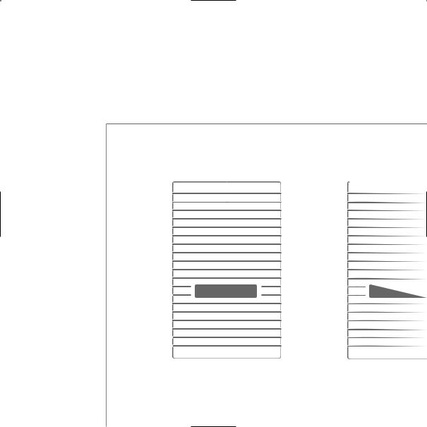
Please note that it takes different configurations to operate Sunways Solar Inverters in different countries. The setting can be adjusted accordingly with the DIP switch «S300» below the display circuit board.
Illustr.: DIP switch «S300» for changing the country setting
Country
Germany
Spain
Switch position
10/15% |
phase-3 |
AFI |
Voltage |
10/15% |
phased 3 |
AFI |
Voltage |
Change
·Opening time after power failure: 3
·Grid monitoring 1-phase
104
To change the country setting, the housing cover must be removed. The DIP switch must be re-positioned to the respective country setting on all three control circuit boards.
When delivered, the Solar Inverters are pre-set to the intended destination country. The pre-set country is indicated by
the first two digits of the serial number:
GB
Germany |
00..... |
Spain |
02..... |
105
2.3Installation
!
Warm |
|
|
|
air |
|
Wall |
min. 300 mm |
Cool air
The Solar Inverter may only be installed by a trained and qualified electrician.
Special tools are needed for installation.
Please read this chapter very carefully.
Ceiling
min. 300 mm
mm 300 |
|

Installation Site Requirements
· Mechanical Load-Bearing Capacity
During assembly, please keep in mind that the Solar Inverter weighs 30 kg. The assembly foundation must be solid and capable of bearing the weight in the long run.
· Thermal Interaction
The assembly foundation must be made of flame-retardant material (unsuitable: wooden or plastic foundation; suitable: concrete and masonry), because the frame of the Solar Inverter can reach up to 70° C.
Maintain a minimum distance of 300 mm to other devices, cabinets, ceilings, cable channels, etc. above, below, and next to the housing.
The Solar Inverter must be installed in an upright position to ensure unobstructed convection.
Do not install several Solar Inverters on top of each other, as they might heat each other up.
If the Solar Inverter is installed in a switch cabinet, make sure the heat is removed to a sufficient degree.
The ambient temperature may not drop below -25° C or rise above +40° C.
To protect the Solar Inverter from unnecessary external heat sources, do not expose
the Solar Inverter to direct sunlight.
GB
·Protection from Moisture and Foreign Objects
Thanks to the high protection level IP 54, the Solar Inverter can be installed indoors as well as in a sheltered outdoor area, but it may not be directly exposed to rain.
Make sure the dust filter on the lower left side is not clogged by contamination.
That would impair the intake of cooling air. Depending on the surroundings, the filter should be cleaned at regular intervals.
107
Mechanical Installation |
Electrical Connection and Cable Entry |
! !
For assembly, please observe the instruc-
tions in the «Setup» leaflet!
As soon as the Solar Inverter is fixed to the assembly frame, it can be electrically connected. The device may only be opened by a qualified electrician. For this purpose, loosen the four lateral hexagon socket screws by one rotation. The cover can now be moved up to the upper rabbet. Fix the cover in position by simply inserting the hexagon key on the lower right side. The wiring space is now accessible.
108

Grid Connection
The Solar Inverter must be connected to the grid with five-cores (L1, L2, L3, N, PE). We recommend a cable cross-section of
5 x 4 mm2.
The Solar Inverter is connected to the supply grid via its internal printed-circuit board terminals.
As an input-to-grid line protection element, we recommend using a 3 x 25 A automatic circuit breaker for the NT 10000. No consumers may be connected to the supply line from the Solar Inverter to the automatic circuit breaker. The Solar Inverter injects in three phases via terminals L1, L2, and L3. Please mind the pin assignment. A wrong assignment may
destroy the device.
GB
|
Alarm relais, RS485 (in and out), |
|
DC1 DC2 DC3 |
irradiation sensor with integrated |
|
|
temperature measurement |
|
DC+ |
USB |
RS 232 |
DC–
AC wiring loom L1, L2, L3, N, PE
Illustr.: Entry openings on the underside of the device
109
 Loading...