


 Loading...
USER S MANUAL
PARTS BOOK
1) For at most use with easiness, please certainly read this manual before starting use.
2) Keep this manual in safe place for reference when the machine breaks down.
From the library of: Superior Sewing Machine & Supply LLC
Quality |
|
Best |
Price |
Best |
Service |
Best |
|
1.Thank you for purchasing our product. Based on the rich expertise and experience accumulated in industrial sewing machine production, SUNSTAR will manufacture industrial sewing machines, which deliver more diverse functions, high performance, powerful operation, enhanced durability, and more sophisticated design to meet a number of user’s needs.
2.Please read this user’s manual thoroughly before using the machine. Make sure to properly use the machine to enjoy its full performance.
3.The specifications of the machine are subject to change, aimed to enhance product performance, without prior notice.
4.This product is designed, manufactured, and sold as an industrial sewing machine. It should not be used for other than industrial purpose.
R
From the library of: Superior Sewing Machine & Supply LLC

From the library of: Superior Sewing Machine & Supply LLC
USER S
MANUAL
From the library of: Superior Sewing Machine & Supply LLC

|
|
|
|
|
|
|
|
|
|
|
|
|
|
|
|
|
|
1. Safety instruction |
6 |
||||
2. Precautions before use |
8 |
||||
3. Locating and using parts of the controller box |
10 |
||||
4. Installation |
11 |
||||
5. Wiring and grounding |
20 |
||||
6. Connection the earth wire of the sewing machine and motor |
23 |
||||
7. Things to be checked after installation |
23 |
||||
8. Program unit part names and method of use |
24 |
||||
9. Simple operation unit part names and method of use |
40 |
||||
10. Fortuna series 5 full function software method of use |
45 |
||||
11. Breakdown and troubleshooting |
70 |
||||
12. How to place for controller |
71 |
||||
13. Block diagram |
72 |
||||
|
|
|
|
|
73 |
From the library of: Superior Sewing Machine & Supply LLC

Be sure to read and keep in mind the following instructions before you install and use thr FORTUNA SERVO MOTOR.
1) Use and Purpose
This product is designed, manufactured, and sold as an industrial sewing machine. It should not be used for other than industrial purpose.
2) Working Environment
 Power Source
 It is desirable that voltage of the power source be kept within the range of
  10% of the rated voltage.
 It is desirable that frequency of the power source be kept within the rage of
  10% of the rated frequency. (50/60
 )
)
 The SERVO MOTOR can be expected to work normaly only in case the foregoing things are kept.
 Electromagnetic Noise
 It is desirable that those equipments causing strong electromagnetic field or high frequency not use the same electrical outlet as this on and stay away from it.
 Temperature and Humidity
 Keep the ambient temperature above 5 degrees and below 40 degrees Centigrade.
 Never use it outdoors and avoid direct ray of light.
 Keep it away from an hot object like a stove.


 30%
30% 


 95%.
95%.
 Never use it near gases and explosives.
 Do not use it at a spot located 1,000m or higer above sea-level.
 Keep the storage temperature higher than 25 degrees below zero and lower than 55 degrees Centigrade when not in use.
3) Installation
Follow the instruction carefully when installing it.
 Be sure to start installing it after pulling the power plug off the outlet.
 Fix the cable so that it may not move, and do not allow the moving parts like belts to be interfered with.(keep distance of at least 25mm from them.)
 Be sure to have the Controller, the Motor and the sewing Machine grounded.
 Be sure that the voltage of power source fits the specification of the Controller before the power is on
  Be sure to use Safety Extra Low Voltage when an extra item or an accessory is fitted into the Controller.
4) Disassembly
 Indisassembling it, be sure to wait at least 360 seconds before taking any action after pulling the plug off the power source after turning it off.
 When pulling off the plug from the power source, be sure to hole the plug itself instead of the wire connected to the plug.
6
From the library of: Superior Sewing Machine & Supply LLC

5) Service and Maintenance
 Make sure that service and maintenance are carried out by a skilled technician.
 Never try to operate with the Motor and the Controller open.
 When inserting a thread into or touching the machine, be sure to turn the power off and step down from the platform.
 Be sure to use standard products specified for replacement of parts.
6) Other Safety Instructions
 Tack care not to let your fingers touch any moving parts including belts.
 In case of remodelling or fitting of additional device, be sure to follow safety standards and do not ever try to go ahead based on your own judgments.
 Do not try to operate with the safety device removed.
 Take care not to let water or coffee or something like those admitted into the Controller or the Motor.
  Never drop the Controller or the Motor to the ground.
 The instructions presented above are for the safer and more proper operation of the Fortuna Servo Motor. Ignoring such instructions could cause damage to the machine or physical injury of the user. Pleasefollowalltheinstructionswhenoperatingthemachine.
7
From the library of: Superior Sewing Machine & Supply LLC
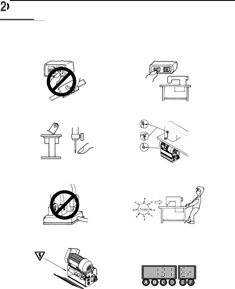
1. Do not turn on the power while stepping on the pedal.
3.Turn off the power when servicing the servomotor or changing the needle.
5.Do not connect multiple servomotor power plugs to the same power strip.
7.Avoid electrical shock when servicing the controller box. (Wait for 6 minutes before opening the cover after turning off the power.)
2. Turn off the power when leaving the servomotor overnight.
4. Be sure to keep the servomotor securely grouned.
6.Install the servomotor away from noise sources, such as highfrequency equipments and welding machines.
8. When an error message Er sppears on the digital display, take a note of the Er code, and then turn on and off before resuming operation(Contact the local dealer if Er message persists on the display)
8
From the library of: Superior Sewing Machine & Supply LLC

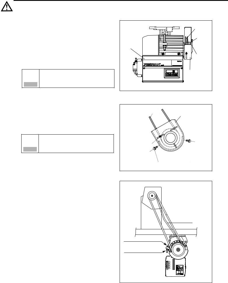
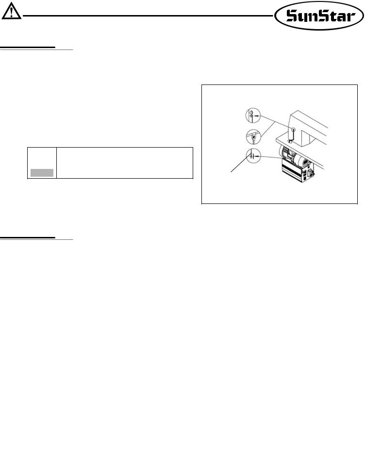
9. Adjust the belt tension to the optimum level.
Belt-tension adjustment should be performed after the motor is mounted on the table : First, loosen both the upper and lower anchoring bolts( , ). The belt tension will then be adjusted by the weight of servo motor itself. Fasten both anchoring bolts.
11.When replacing the fuse, use a standard item, opening the cover as shown in the diagram.
10.Clean it every two or three weeks so that no dirt or a dirty substance may be piled up.
12.Make the length of the cable connected with an outside parts like stand-up pedal as short as possible.
F1 |
250V/6.3A |
|
|
F2 |
250V/6.3A |
|
|
F3 |
250V/6.3A |
|
|
F4 |
250V/1A |
|
|
9
From the library of: Superior Sewing Machine & Supply LLC

1) Left and right side of control box
Control box left side |
Control box right side |
Motor Power Cable |
|
|
Encoder Connector |
|
(Green) |
AC Power switch |
|
Standard Solenoid |
OPTION |
|
|
Connector |
|
Switch and Lamp |
Connector for Position |
|
Sensor(Black) |
Foot-lift Solenoid(Green) |
|
Right lift Solenoid(Blue) |
Program Unit |
|
Connector(White) |
Tension-release and |
|
Auxiliary solenoid(White) |
|
2) Rear panel
Caution |
Motor |
AC INPUT |
10
From the library of: Superior Sewing Machine & Supply LLC
1) Mounting your Servo Motor on the table
 Make sure that the holes are bored on the table as shown in the figure.
Table
Belt Hole
41 Cable-Hole
 Insert three motor-fixing bolts through the three holes on the table. Attach the motor base padded with vibration-proof rubber, and slide flat and spring washers over the bolt stems, and then fasten the bolts with nuts.
Motor-Fixing Bolts
Table |
Motor-Fixing Bolts(3ea) |
Vibration-Proof rubber
Flat Waser
Spring Waser
Nut
Base
R
Controller Box
Motor-Fixing Bolts(3ea)
 Make sure that the center of motor pulley is matched to that of the sewing machine before tightening the motor-fixing bolts and nuts.
11
From the library of: Superior Sewing Machine & Supply LLC
2)Assembling the belt cover and adjusting the belt tension
(1) Belt cover assembling procedure
 Upon the completion of the motor mounting, bring the two pulleys of motor and sewing machine closer to each other, by pulling back the sewing machine. You can then mount the belt easily as shown in the figure.
Make sure that the power is off before
assembly.
Warning
 Place the belt cover B , making sure that the belt cover does not contact the belt, and then fasten the cover with the fixing screw.
Do not remove the belt cover.
If a finger slips into the belt, it might be broken or
Warning cut off.
Pulley
Belt Guide
Fixing
Screw
Controller Box
Belt Guide
Belt Cover A
A
Belt
Belt Cover B
Belt Guide Fixing Screw
Belt Cover Fixing Screw
(2) Adjusting the belt tension
 Optimum Tension Level
 The optimum tention level is achieved when the belt is pushed by 5-10mm when the top surface portion of the belt at about 30-50mm above the tabletip is pressed by a finger with a force of~1
 m/sec2 or 1 Newton.
 Adjusting the Tension Level
 If the tension level is out of the optimum range, adjust the tension as follows. First, loosen both the upper and lower nuts for the anchor bolt, letting the belt be stretched by the motor weight itself. Second, tighten the upper nut only to the extent that the motor does not move. Third, fasten the bottom nut tightly so that the motor is securely fixed.
 5~10mm
30~50mm
Upper Nut for the Anchor Bolt
Lower Nut for the Anchor Bolt
12
From the library of: Superior Sewing Machine & Supply LLC

3) Mounting and adjusting the foot-lift solenoid
(1) SunStar KM-235 Model
 Attach the main power switch first since the power switch is located normally in between the solenoid brackets.
 By referring to the figure on the right and the mounting instructions enclosed in the packaging box, locate the insertion surface of the oil pan, and then attach the foot-lift solenoid.
No. |
Solenoid No. |
Applicable Models |
|
|
|
1 |
SPF-2 |
KM-235A, B |
|
|
|
(2) SunStar KM-250 Model
 First, assemble a panel for the attachment of presser foot solenoid on the back of KM-250.
 Attach the presser foot solenoid to a bracket A .
 Attach the bracket
 A with the presser foot solenoid to the panel above.
 Attch a crank to a solenoid shaft and then connect it to a sewing machine.
 Place a cover on the solenoid.
(3) SunStar Special-specification models
The same mounting procedure for KM-235 model is applicable
for other models listed below.
No. |
Solenoid No. |
Applicable Models |
1 |
|
KM-750-7, KM-750BL-7 |
2 |
SPF-3 |
KM-790-7, KM-790BL-7 |
3 |
|
KM-857-7, KM-867-7 |
4 |
SPF-4 |
KM-560-7 |
5 |
SPF-6 |
KM-957-7, KM-967-7 |
6 |
SPF-8 |
KM-757-7 |
7 |
SPF-9 |
KM-640BL-7 |
(4)Adjusting the stroke(Gap) of the automatic foot-lift solenoid
 Check point
Check to make sure that the stroke-adjusting screw is located at the center of the solenoid axis, i.e., the solenoid should be assembled in parallel with the bottom surface of the table. If the solenoid is not in paralle, make an adjustment so that the screw is in parallel with the center of the solenoid axis using the connection link-fixing screw.
 Adjusting Procedure
The verical travel distance of the presser foot can be adjusted by the stroke-adjusting screw. First, Loosen the two fixing screws, and adjsut the vertical stroke using the stroke-adjusting screw. loosening and tightening the stroke-adjusting screw will decrease and increase the verical stroke of the presser foot respectively. After the adjustment, fasten the fixing screw tightly.
|
|
|
|
|
|
|
|
|
|
|
|
|
|
|
Mounting Position |
||
|
|
|
for Legs(4) |
||
|
|
|
|
|
|
|
Oil Pan Insertion Surface |
|
|
|
|
|
|
|
|
|
|
|
|
|
|
|
|
|
Mounting Position(4) |
|
|
|
|
|
for Automatic |
|
|
|
|
|
Foot-Lift Solenoid |
|
|
|
|
|
|
|
|
|
|
|
Belt Holes |
|
|
|
|
|
|
|
Specification viewed from the table bottom |
||
|
|
|
|
|
|
|
|
|
|
|
|
|
Solenoid Bracket A |
Cover for Foot-Lift Solenoid |
|||
|
|
|
|||
KM-250 Rear Panel
Oil Pan Insertion Surface
Mounting Position(4)
for Automatic
Foot-Lift Solenoid
Belt Holes
Specification viewed from the table bottom
Connection Link-
Fixing Screw
Oil Pan |
Stroke-Adjusting Screw |
Solenoid Axis
Fixing Nuts
13
From the library of: Superior Sewing Machine & Supply LLC

4)Mounting the position sensor (Synchronizer) and setting the film
(1)Mounting the position sensor(Synchronizer)
 SunStar thread-cutting sewing machine.
All SunStar thread-cutting sewing machines are equipped with a position sensor. Users, therefore, are required to the adjust the film position, if necessary, as shown in the figure.
L Wrency
Pulley
Synchro shaft-fixing screw(2)
Synchro shaft
Photo film
(Adjusted left and right)
Photo INTERRUPT
Upper Shaft
COVER
P.C.B Holder
 All other sewing machines(including other manufacturers’ brands)
First, attach the position sensor-mounting adapter to the upper shaft of the sewing machine. Second, attach the position sensor-fixing plate to the body of the sewing machine as shown below in the figure. Third, secure the position sensor to the adapter with the fixing screws.
Adapter
Position Sensor-Fixing Bolts |
Pulley |
|
Position Sensor-
Fixing Plate(Type A)
Position Sensor
Cable
Position Sensor-Fixing Plate(Type B)
Nylon Cable Tie
Fiixing Bolt for Position
Sensor-Fixing Plate
14
From the library of: Superior Sewing Machine & Supply LLC
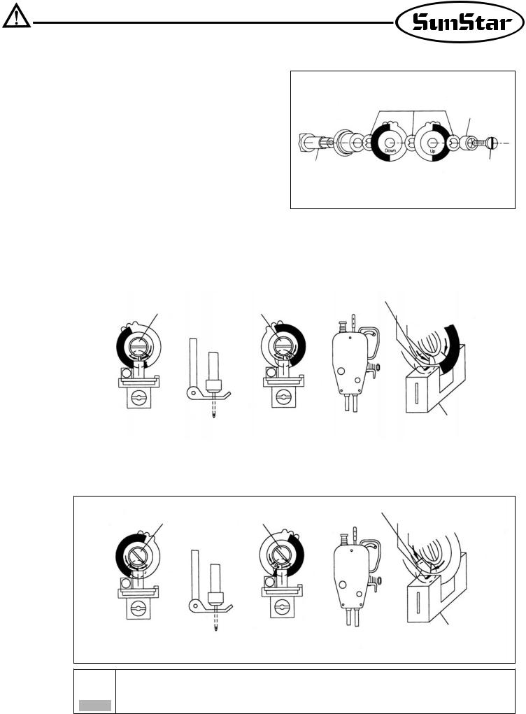
(2) Adjusting the film of the position sensor
 Assemble the films and position sensor in the order as shown in the figure.
Fixing Washer
Fixing Bushing
Position Sensor Shaft |
Film-Fixing Screw |
 Upon the completion of the assembling, position the needle shaft tight at the rising point from the lowest needle position by manually rotating the pulley. Loosen the film-fixing screw, and adjust the DOWN film so that the film-adjsting line and the sensor housing calibration line are matched. Tighten the film-fixing screw just to the extent that the film can not be rotated. Likewise, position the thread take-up at the highest position. Loosen the film-fixing screw, and adjust the UP film as shown in the figure, while using caution not to move the DOWN film which is already adjusted earlier. Tighten the adjusted film with the fixing screw.
|
|
|
Setting Position |
Fixing Nut |
|
Fixing Nut |
Sensor Calibration Line |
|
|
|
Film-Adjusting Line |
|
2mm turning around |
|
Sensor Housing |
Down Film Adjustment |
from the lowest |
Up Film Adjustment |
The highest position |
|
position of needle bar |
of take-up lever |
|
|
|
||
|
|
|
|
(3) Adjustion the films of reverse rotation sewing machines
 For reverse-rotation sewing machines, the film-adjusting lines located at right edge of the UP and DOWN film should be matched to the center line of the sensor.
|
|
Setting Position |
Fixing Nut |
Fixing Nut |
Sensor Calibration Line |
|
|
Film-Adjusting Line(Reverse Rotation) |
Down Film Adjustment 2m turning around from the lowest
position of needle bar
Sensor Housing
Up Film Adjustment The highest position of take-up lever
After adjustment the film of the position detector, be sure to rotate the motor for 3~5 seconds by pedalling so
that the Controller may remember location of the film.
Caution
15
From the library of: Superior Sewing Machine & Supply LLC
5)How to equip and adjust a built-in location detector(synchronizer)
(1)How to equip the built-in location detector (synchronizer)
 In case of a SunStar thread trimmer
When a built-in location detector(synchronizer) for the sewing machine with the SunStar thread trimmer is equipped, all that the users need to do is to simply adjust the location of magnetic for detection according to their needs.
Locate detector
(synchronizer)
Position magnetic up
Upper
Shaft
Position magnetic down
Position magnetic up
Locate detector Sewing machine (synchronizer) pulley
Sewing machine
Position magnetic down
16
From the library of: Superior Sewing Machine & Supply LLC

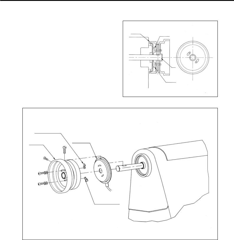
(2) How to adjust the magnet of the location detector
Locate detector(synchronizer)
Assemble the detector in order following the pictures.
 Once assembling is completed, power the controller on and step on the pedal. At this time, make sure that the needle moves up and down. Stop the needle at a desired location by moving the magnet back and forth along the location where the needle stops.
The highest position of take-up lever
Normal rotation |
Normal rotation |
direction |
direction |
Locate detector |
2mm turning around |
(synchronizer) |
from the lowest |
|
position of needle bar |
(3)How to adjust a location detector in case of a reverse rotation sewing machine
 It is the same as that used for the normal rotation direction
The highest position of take-up lever
Reverse rotation |
Reverse rotation |
direction |
direction |
Locate detector |
2mm turning around |
(synchronizer) |
from the lowest |
|
position of needle bar |
After adjusting a location detector, rotate the motor by stepping on the pedal for 3~5 seconds so that a
controller can remember the location.
Caution
17
From the library of: Superior Sewing Machine & Supply LLC
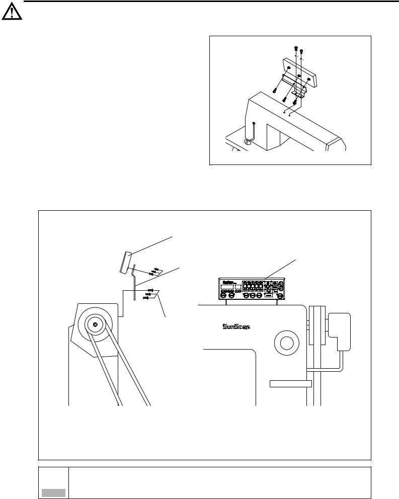
6) Mounting the Program Unit(P/U)
(1) SunStar KM-235 Sewing Machine
First, attach the P/U bracket to the P/U using three fixing screws and a supporting bolt with nut attached on it as shown in the figure. Second, securely attach the P/U to the head of the sewing machine using two fixing screws and washers, keeping a 3~4mm distance between the bottom surface of the nut and the base of the supporting bolt.
(2) Other SunStar thread-machine
First, attach the P/U bracket to the P/U using the four fixing screws. Second, attach the P/U to the main body of the sewing machine using the three bracket-fixing screws as shown in the figure.
Program Unit
Program Unit
P/U Bracket
P/U Bracket-Fixing
Screw(3)
Fix the cable using the cable tie so that cable is not in the way of the belt.
Caution
18
From the library of: Superior Sewing Machine & Supply LLC

7) An example of installing the SunStar sewing machine
19
From the library of: Superior Sewing Machine & Supply LLC
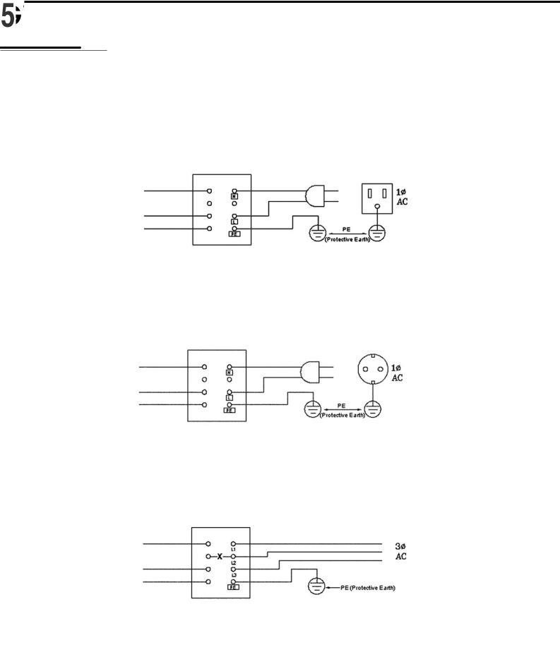
1)Specification of the power plug
(1)Single phase 100V~120V
|
Switch Box |
Control Box |
110V |
|
EARTHV |
|
|
(2) Single phase 200V~240V |
|
|
|
|
Switch Box |
Control Box |
220V |
|
EARTHV |
|
|
(3) Three phase 200V~240V |
|
|
|
|
Switch Box |
Control Box |
220V |
|
EARTHV |
|
|
Be sure to connect Protective Earth |
|
2) Specification of electric current in wiring of power plug
Be sure to use wiring materials which can stand electric current of higher than 15A.
20
From the library of: Superior Sewing Machine & Supply LLC
3) Name and description on the outside connector of control box
 Standard solenoid connector
[ Shape of pin ] |
[ No. of pin ] |
1, 5 |
Back Tack Solenoid |
4, 8 |
GND, VDC |
|
2, 6 |
Thread-Cutting Solenoid |
|
(DC 46V or DC 32V) |
|
3, 7 |
Wiper Solenoid |
9, 10 |
Button |
to insert/delete the |
|
|
|
back-tack operation |
|
|
|
11, 12 Button |
for manual back- |
|
|
|
|
tack operation |
|
 Tension-release and auxiliary solenoid
Connector Color White
Auxiliary Solenoid
Tension-Release Solenoid
 Foot-lift solenoid
Connector Color Green
Foot-Lift Solenoid Switch
Foot-Lift Solenoid
 Right/Left solenoid(Used in twin-needle sewing machine)
Connector Color Blue
Right-Needle Control Solenoid
Left-Needle Control Solenoid
 Switch and lamp(Used in twin-needle sewing machine)
[ Shape of pin ] |
[ No. of pin ] |
5V |
GND |
5V |
4/4 (N.C) |
L LED |
3/4 (N.C) |
R LED |
2/4 (N.C) |
L S/W |
1/4 (N.C) |
R S/W |
(N.C) |
4) How to change the electric voltage supplied for solenoid (The factory installed setting is J2)
J2)
 This is to make the movement of solenoid smooth in times of fluctuation in the incoming electric voltage.
  Set Value for electric voltage supplied (for 220V series) for Solenoid against the incoming voltage.
For 30V-regular Solenoid
Incoming Voltage |
Set Value |
|
|
Below 210V |
J5 |
|
|
210V~230V |
J6 |
|
|
Above 230V |
J7 |
|
|
For 24V-regular Solenoid
Incoming Voltage |
Set Value |
|
|
Below 180V |
J5 |
|
|
180V~190V |
J6 |
|
|
Above 190V |
J7 |
|
|
21
From the library of: Superior Sewing Machine & Supply LLC

 Set Value for electric voltage suplied (for 110V series) for Solenoid against the incoming voltage.
For 30V-regular Solenoid
Incoming Voltage |
Set Value |
|
|
Below 100V |
J5 |
|
|
100V~120V |
J6 |
|
|
Above 120V |
J7 |
|
|
For 24V-regular Solenoid
Incoming Voltage |
Set Value |
|
|
Below 90V |
J5 |
|
|
90V~100V |
J6 |
|
|
Above 100V |
J7 |
|
|
 Setting of pin
22
From the library of: Superior Sewing Machine & Supply LLC
 Method
Connect the motor and sewing machine using the ground wire (green, green/yellow) as shown in the figure. Make sure that the factory-connected ground wire between the controller box and motor is securely in place.
Failure to ground the motor can cause abnormal operations, such as overspeed rotation or unwanted
Caution stitching.
1) Before the power is on...
 Make sure that the incoming voltage is in accordance with that shown in the name plate of the Control box.
 Check whether the following connectors are connected.
 Connector for incoming AC power source
 Connector for motor power
 Connector for motor encoder
 Connector for pedal
 Connector for position detector
 Connector for others (option, knee-lift, program unit etc.)
 Check to see whether the belts are in touch with the wiring.
 Check the tensile strength of the belts.
 Check to see the fixing nuts for pulley are tightly fastened.
 Check whether the sewing machines are right kinds (Chain Stitch S/M, Lock Stitch S/M)
 Check the rated voltage for Solenoid (Refer to How to change the electric voltage supplied for Solenoid ))
2) After the power is on...
 Check whether the lamp for the position detector is on. (Except in the case of built-in position detector)
 Check whether the program unit is working.
 Check the direction of rotation of the Sewing Machine.
 In case the direction of rotation is not right, action shall be taken to change set it right, referring to
 the methods of changing the program and the list of changing functions (N. 65 in Group A )
 Check to see whether there are abnormal heat, smell or noise nearby.
  In case there are, turn the power off and call our regional office.
23
From the library of: Superior Sewing Machine & Supply LLC

1) Program unit part names
|
Start B/T Selection Button |
|
2--Digit Displayer |
End B/T Selection Button |
|
Button to Select Needle Plate Location When Machine Stops |
||
Sunstar Logo |
||
Button to Select Presser Foot-lift Location When Machine Stops |
||
4-Digit Displayer |
||
Thread-trimmer and Wiper Selection |
||
|
||
|
Button to Change the Sewing Speed Installation |
|
|
Pattern Work Connecting Button |
|
|
Constant Sewing Speed Selection Button |
|
1/2 Stitch Button |
Pattern Work Selection Button |
|
|
||
Button for Program Change |
|
|
Button for Counter Use after Counter Programming |
|
|
Button to use Edge Sensor Selection after Edge Sensor Programming |
|
|
Button to Save Program Changes |
|
2)Program Unit Method of Use
(1)4-Digit Displayer and 2-Digit Displayer Functions and Method of Use
A. 4-Digit Displayer and 2-Digit Displayer Functions
<Initializing screen>
 When you turn the power on, you will see a screen as shown in the figure. The 4-digit displayer shows the start and end B/T sewing and the 2-digit displayer shows the current abbreviation for the letters or numbers shown in the 4-digit displayer (bt: the abbreviation for back tack),
<Example of error detection>
 The 4-digit displayer shows the error number for each type of error discovered and also shows the programmed value after it has been
programmed. The 2-digit displayer shows the number of the parameter <Example of selection of number 2 item in Group A> specific item's content or name which is shown in the 4-digit displayer.
The 4-digit displayer and 2-digit displayer show the current condition. Therefore the user should always check it
before using the machine.
Caution
24
From the library of: Superior Sewing Machine & Supply LLC

B.Method of Use: 4-Digit Displayer and 2-Digit Displayer
a. Method to change the start and end B/T stitch numbers
In order to change the start B/T stitch numbers which is programmed when you first purchase this machine, you must use the  ,
,  buttons. If you want to
change the end B/T stitch numbers, you must use the  ,
,  buttons. The program range is from 0 to 9.
(Ex: How the screen looks when changing both start and end B/T stitch numbers to 4).
b. Method to check or change the specifics of the parameter
 Press the
  button and as you press it, also press the
  button. Then you can either check or change the programming items for the parameter of group A. (A group
  , B group
  , C group
  D group
  )
)  Users should turn the machine off to select B, C, or D group. While pressing the
  button, turn the power switch on. The screen will be changed to the initial screen after showing the "PrEn" message. Then, the users can select B, C, or D group by pressing B, C, or D button while
holding program  button.
 You can move to the parameter item you want with the
  and
and  buttons. The parameter item number will appear in the 2-digit displayer and the wanted value will appear in the 4-digit displayer.
(Ex) Screen showing the maximum speed limit preset in the item 2 of A group)
 After using the
  (increase) button and
  (decrease) button to choose the value you want, press the
  (Enter) button and save the value you chose. (Ex: Reducing the maximum sewing speed limit from 4000RPM to
3000RPM).
 After saving, press the
  button and go back to the initial screen.
Be aware that if you don't press  after changing the programmed value for the parameter item, the value will not be saved. When the B, C, or D group selection is completed, users should turn off the machine first and restart to secure the selected group.
Caution If the user changes the programmed value from the parameter specifics carelessly, the user may cause break down or physical damage to the machine. The user must therefore be well-trained before changing the parameter group.
(2) Method of Use |
Stitch Button Function |
 When necessary, make
  stitches by pressing the
  stitch (
 ) button.
 When the needle plate makes a down stop, shortly press the
  stitch (
 And when the needle plate makes an up stop, shortly press the
  stitch (
) button once and the needle plate will make an up stop. ) button once and the needle plate will make a down stop.
Be aware that if you are continuously pressing the  (
( ) button, the machine will keep on moving at the
  stitch
( ) speed.
Caution
25
From the library of: Superior Sewing Machine & Supply LLC

(3) Method of Use: Start B/T Button
This button is used when the user wants to prevent threads from loosening at the end of the sewing work. If the user presses this button in sequence, the location on the lights will change. This button offers the following three functions.
When sewing starts, B/T sewing is operated with
When sewing starts, B/T the sewing does not operate.
button
When sewing starts, B/T sewing is operated with the
button
Using the A, B buttons in the 4-digit displayer, the user can program the B/T number of stitches he/she wants.
Be aware that if the start B/T stitch is set to '0' in the 4-digit displayer, the start B/T sewing is impossible.
Caution
(4) Method of use: End B/T Button
This button is used when the user wants to prevent threads from loosening at the end of the sewing work. If the user presses this button in sequence, the location on the lights will change. This button offers the following three functions.
|
When sewing ends, B/T |
|
sewing can be operated |
When sewing ends, B/T |
with the |
sewing does not operate. |
|
|
button. |
|
|
When sewing ends, B/T sewing can be operated with the
button.
Using the C, D buttons in the 4-digit displayer, the user can program the B/T number of stitches he wants.
Be aware that if the end B/T stitch is set to '0' in the 4-digit displayer, the start B/T sewing is impossible.
Caution
(5) Method of Use: The Needle Plate Position Selection Button When the Sewing Machine Stops
When the user turns the power on, one of the up stop or down stop lights in the program unit panel needle plate is always left on. The user can change the stop location by pressing the button.
When machine stops while sewing, the needle plate makes an up stop.
When machine stops while sewing, the needle plate makes a down stop.
26
From the library of: Superior Sewing Machine & Supply LLC
Loading...