

Sunrise Medical Guardian IC-5307, Guardian IC-5107, Guardian IC-5207, Guardian IC-5110, Guardian IC-5410 User Instructions And Warranty
...Page 1

Guardian
®
Homecare Bed
User Instructions & Warranty
Manual Bed Models IC-5307 IC-5207 & IC-5107
Semi Electric Bed Models IC-5310 IC-5210 & IC-5110
Full Electric Bed Model IC-5410
Lit de soins à domicile Guardian
®
Mode d’emploi et garantie
Lit manuel modèles IC-5307 IC-5207 & IC-5107
Lit semi-électrique modèles IC-5310 IC-5210 & IC-5110
Lit électrique 3 positions modèle IC-5410
Cama para Cuidados en el Hogar Guardian
®
Manual de Instrucciones y Garantía
Modelos de Cama Manual IC-5307 IC-5207 & IC-5107
Modelos de Cama Semieléctrica IC-5310 IC-5210 & IC-5110
Modelo de Cama Totalmente Eléctrica IC-5410
Page 2

2
English
Sunrise Listens
SUNRISE LISTENS
Thank you for choosing a Sunrise Medical bed. We want to hear your questions or comments about this manual, the safety and reliability of your bed and the service you receive
from your Sunrise Medical supplier. Please feel free to write or call us at the address and
telephone number below:
Sunrise Medical
Customer Service Department
7477 East Dry Creek Parkway
Longmont, CO 80503
(303) 218-4600 or (800) 333-4000
FOR ANSWERS TO YOUR QUESTIONS
Your authorized supplier knows your bed best and can answer most of your questions about
bed safety, use and maintenance. For future reference, fill in the following.
Supplier:_________________________________________________
Address: _________________________________________________
Telephone: _______________________________________________
Serial #: _________________________________________________
Date/Purchased:___________________________________________
This manual contains important safety and maintenance instructions. Please read
it carefully before using your homecare bed and refer to it as often as needed for
safe and efficient use.
If you have questions regarding the safe use and/or assembly, maintenance or
specifications of your bed, contact Customer Service at 800-333-4000, 303-2184600 or from Canada at 800-263-3390. Please have the Model and Serial Number
of the product available.
For service and repair, remember your authorized Sunrise Medical dealer is able to
provide the assistance you need.
Keep this manual in a safe place for future reference.
Page 3

Table of Contents
3
English
TABLE OF CONTENTS
INTRODUCTION .................................................................................... 2
TABLE OF CONTENTS ............................................................................. 3
IMPORTANT WARNINGS......................................................................... 4
BED WEIGHT CAPACITY ......................................................................... 5
SET-UP................................................................................................ 5
ASSEMBLY ........................................................................................... 6
Manual Bed Assembly ......................................................................... 6
Semi-Electric Bed Assembly ................................................................. 8
Full-Electric Bed Assembly................................................................... 10
OPERATION.......................................................................................... 12
Manual Bed Operation......................................................................... 12
Semi-Electric Bed Operation ................................................................ 13
Full-Electric Bed Operation .................................................................. 13
Locking/Unlocking Casters................................................................... 13
MAINTENANCE ..................................................................................... 14
CLEANING / SPECIFICATIONS................................................................. 15
TROUBLESHOOTING .............................................................................. 16
IMPORTANT WARNINGS FOR ACCESSORIES............................................... 17
WARRANTY .......................................................................................... 19
FRANÇAIS............................................................................................... 20
ESPAÑOL ................................................................................................ 38
Page 4

IMPORTANT WARNINGS
(See pages 17 & 18 for Important Warnings for Accessories)
WARNING
RISK OF SERIOUS INJURY OR DEATH. Bed power cord has a hospital-grade 3-prong
grounding plug. Do not defeat grounding safety feature by using 3-prong to 2prong adapter. If necessary, have outlet ground reliability checked by a qualified
electrician. Failure to do so could result in shock or electrocution.
WARNING
RISK OF SERIOUS INJURY. When operating the bed, make sure that the occupant
is positioned within the boundaries of the bed and that no extremities extend
over the side or between the bed rails.
WARNING
RISK OF SERIOUS INJURY. Closely monitor children and high-risk individuals in or
around bed.
WARNING
RISK OF SERIOUS INJURY. Electromagnetic Interference (EMI) may influence electronic equipment. Exercise caution when using hand-held transceivers around the
electric bed. If unintended movement occurs due to EMI, unplug the electric bed
immediately. Leave unplugged during transmission, otherwise injury may occur.
WARNING
POSSIBLE DAMAGE OR INJURY. The homecare bed is not intended to be used as a
means of transport. Use an approved transport device when transporting a
patient.
WARNING
POSSIBLE DAMAGE OR INJURY. The homecare bed was designed to be used in a
home care setting only and is not intended for use in nursing homes or hospitals.
WARNING
POSSIBLE DAMAGE OR INJURY. Do not allow more than one person on the bed at a
time.
WARNING
POSSIBLE DAMAGE OR INJURY. Distribute body weight evenly over surface of bed.
Do not put entire body weight only on raised foot or head sections of bed, otherwise damage to bed may occur.
WARNING
Risk of serious injury. Keep cord away from heated surfaces.
WARNING
Possible damage or injury. Do not use outdoors.
SAVE THESE INSTRUCTIONS.
4
English
Important Warnings
Page 5

BED WEIGHT CAPACITY
The homecare bed has a capacity of 450 pounds (204 kg) evenly distributed on the sleeping surface. This is the total weight of the occupant, mattress, bedding, accessories and
other medical equipment in use. Exceeding the weight limit will void the warranty.
SET-UP
Check all bed components for obvious damage to the carton or its contents. Inspect each
item carefully for dents, scratches or any other visible damage. If damage is evident, contact your local Sunrise Medical dealer.
WARNING
Before assembling bed, inspect all parts for shipping damage. If damage is evident, do not use bed. Contact qualified personnel immediately.
CAUTION– Do not plug in or operate bed controls before bed is completely assembled.
Damage to bed components or injury may occur.
The bed is packaged in three separate cartons:
1. Bed Ends
(Figure 1)
•Headboard
•Footboard
•Hi/Lo Connecting Rod (not included with fixed height or two crank models)
•Four casters (two locking and two non-locking)
2. Foot Spring
(Figure 2)
•Foot spring (electric beds include pendant, control box and power cord)
•Emergency crank handle (electric beds only)
3. Head Spring
(Figure 3)
For electric beds, check for damage to power cord and plug. Inspect control box for damage
to the connectors and make sure the motor plugs fit properly into the control box. See
(Figure 48) in Maintenance section for correct installation of connecters into control box.
WARNING
POSSIBLE INJURY. Do not use bed if power cord or plug is damaged. Refer servicing to qualified technician.
Set-up
5
English
Head Foot Bed
Model No. Bed Type Section Section End Set
IC-5410 Full-Electric IC-5000 IC-5490 IC-5401
IC-5310 Semi-Electric Single Crank Hi/Lo IC-5000 IC-5890 IC-5301
IC-5210 Semi-Electric Two Crank Hi/Lo IC-5000 IC-5890 IC-5200
IC-5110 Semi-Electric Set Height IC-5000 IC-5890 IC-5100
IC-5307 Manual Single Crank Hi/Lo IC-5000 IC-5770 IC-5301
IC-5207 Manual Two Crank Hi/Lo IC-5000 IC-5770 IC-5200
IC-5107 Manual Set Height IC-5000 IC-5770 IC-5100
Major Bed Components Part Numbers
1
2
3
Page 6

ASSEMBLY
MANUAL BED ASSEMBLY
WARNING
After any adjustments, repair or service and before use, make sure all attaching
hardware is tightened securely.
CAUTION– Do not operate bed controls before bed is completely assembled. Damage to
bed components or injury may occur.
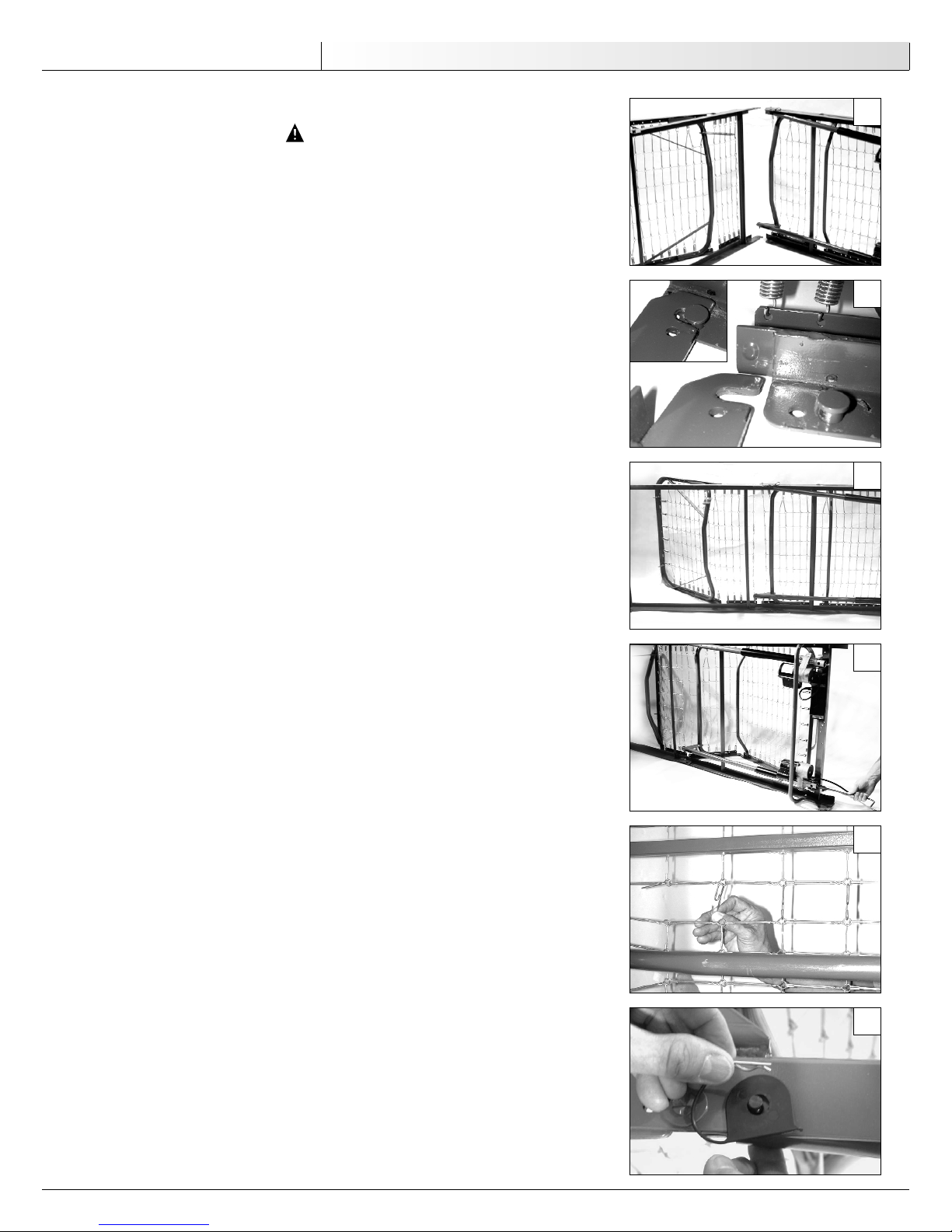
Connecting Head and Foot Sections
1. Place the head end at a right angle (90 degrees) to the foot end. The head end
should be on its side to your left with the center mounting hooks to your right
(Figure 4). The foot end (with crank handles) should be to your right with the head
spring pull tube at the top and the center mounting rivets pins facing to the left.
2. Engage the head end hooks into the foot end pins
(Figure 5).
NOTE– It may be necessary to lift slightly on the head end or foot end to secure the
mounting hooks and pins.
3. Rotate the back section 90 degrees, making the frame assembly a straight line
(Figure 6).
Connecting Fabric of Head and Foot Sections
1. Turn foot crank clockwise to raise the foot end (see Manual Bed Operation) (Figure 7).
2. Hook together all the links on the mattress surface
(Figure 8).
Connecting Head Spring Drive Tube
1. Disconnect the head drive tube assembly from the side frame of the foot spring by
removing the hitch pin, grommet and washer from the clevis pin
(Figure 9).
2. Extend the inner drive tube shaft until the detent button clicks into the adjustment
hole of the outer drive tube. Make sure the detent button protrudes through the
adjustment hole of the extended drive tube arm
(Figure 10). The drive tube arm will
line up with the lift arm slot.
3. Attach the drive tube end assembly to the lift arm of the head spring by inserting
the clevis pin into the lift arm slot. Reconnect the grommet and washer and fasten
with hitch pin
(Figure 11).
4. After assembling frame, lay bed flat.
6
English
Assembly
4
6
8
9
7
5
Page 7

Assembling the Bed Ends
NOTE– The headboard is taller than the footboard.
1. Stand the headboard next to the head section of the bed.
2. Lift the head end and engage the pins in the frame into the hooks on the headboard
(Figure 12). Leaning the headboard back slightly will help the pins fit into the
hooks more easily.
3. Lift the foot section of the bed and engage the pins on the frame into the hooks on
the footboard in the same manner.
WARNING
Make sure head and foot ends are securely locked to the head and foot boards
before using bed.
Installing the Casters
NOTE– For maximum locking stability, assemble the two locking casters diagonally at
opposite ends of the bed.
Install all four casters simply by raising the bed ends from the floor and pushing the stem
up into the caster socket in each bed leg
(Figure 13).
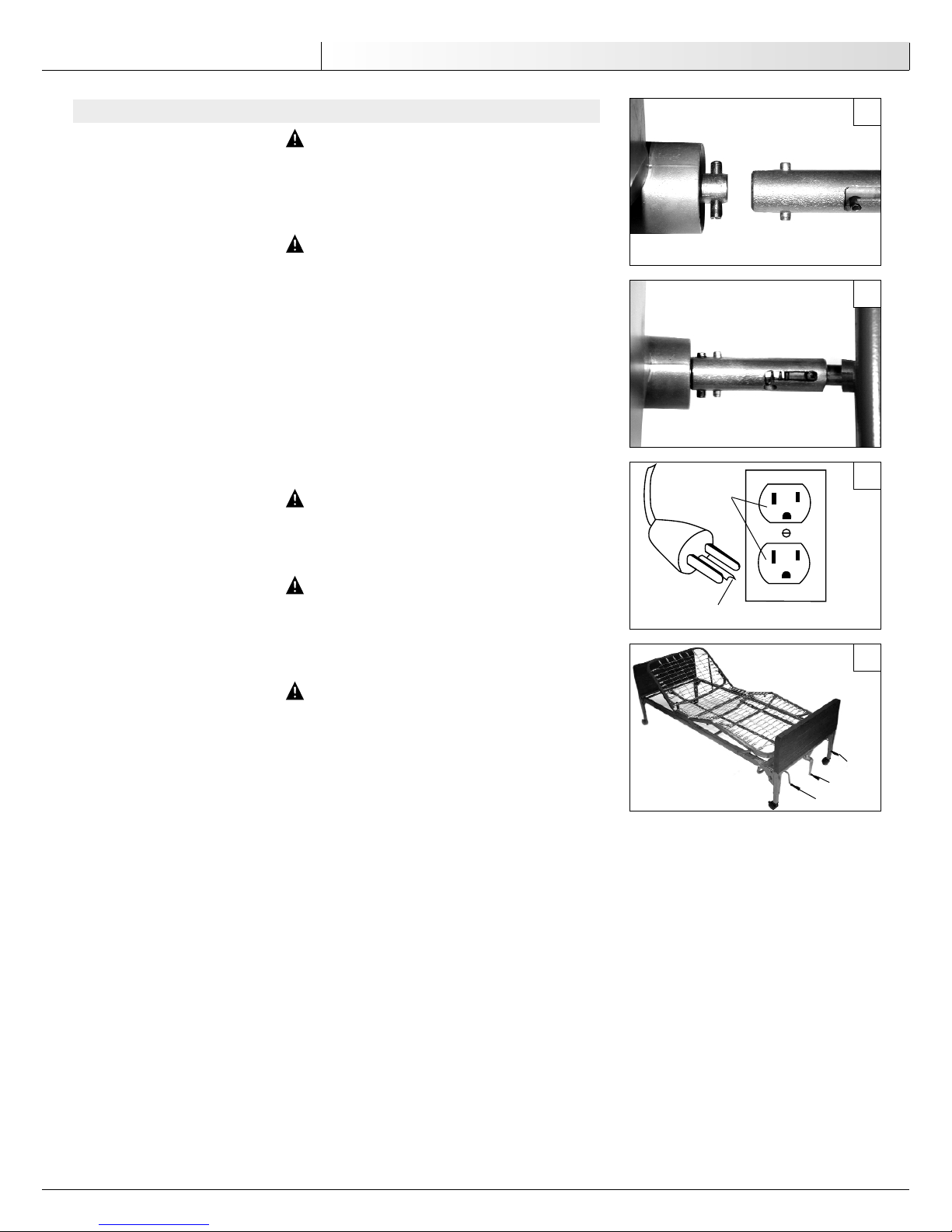
Assembling Hi/Lo Connecting Rod
NOTE– This section does not apply to fixed height or two crank models.
NOTE– The connecting rod has two sections: The inner rod has a detent button, and the
outer rod has two positioning holes and one storage position hole.
1. Remove plastic caps from both ends of connecting rod.
2. Depress detent button on inner rod and insert into outer rod. Slide the inner rod in
place and engage the detent button into the first positioning hole.
3. The connecting rod mounts directly into the head and foot end gearbox output shafts
(Figures 14 & 15).
Assembly
7
English
10
11
12
13
14
15
Page 8

SEMI-ELECTRIC BED ASSEMBLY
WARNING
After any adjustments, repair or service and before use, make sure all attaching
hardware is tightened securely.
CAUTION– Do not operate bed controls before bed is completely assembled. Damage to
bed components or injury may occur.
Connecting Head and Foot Sections
1. Place the head end at a right angle (90 degrees) to the foot end. The head end
should be on its side to your left with the center mounting hooks to your right
(Figure 16). The foot end (with motors) should be to your right with the head
spring pull tube at the top and the center mounting rivets pins facing to the left. For
electric foot ends, the motors should be to your right, and for manual foot ends the
crank handles will be to your right.
2. Engage the head end hooks into the foot end pins
(Figure 17).
NOTE– It may be necessary to lift slightly on the head end or foot end to secure the
mounting hooks and pins.
3. Rotate the back section 90 degrees, making the frame assembly a straight line
(Figure 18).
Connecting Fabric of Head and Foot Sections
1. Press the “FOOT UP” button on the hand pendant (see Semi-Electric Bed Operation) or
use emergency crank to turn motor shaft clockwise to raise the foot end
(Figure 19).
2. Hook together all the links on the mattress surface
(Figure 20).
Connecting Head Spring Drive Tube
1. Disconnect the head drive tube assembly from the side frame of the foot spring by
removing the hitch pin, grommet and washer from the clevis pin
(Figure 21).
2. Extend the inner drive tube shaft until the detent button clicks into the adjustment
hole of the outer drive tube. Make sure the detent button protrudes through the
adjustment hole of the extended drive tube arm
(Figure 22). The drive tube arm will
line up with the lift arm slot.
3. Attach the drive tube end assembly to the lift arm of the head spring by inserting
the clevis pin into the lift arm slot. Reconnect the grommet and washer and fasten
with hitch pin
(Figure 23).
4. After assembling frame, lay bed flat.
8
English
Assembly
16
18
20
21
19
17
Page 9

Assembling the Bed Ends
NOTE– The headboard is taller than the footboard.
1. Stand the headboard next to the head section of the bed.
2. Lift the head end and engage the pins in the frame into the hooks on the headboard
(Figure 24). Leaning the headboard back slightly will help the pins fit into the
hooks more easily.
3. Lift the foot section of the bed and engage the pins on the frame into the hooks on
the footboard in the same manner.
WARNING
Make sure head and foot ends are securely locked to the head and foot boards
before using bed.
Installing the Casters
NOTE– For maximum locking stability, assemble the two locking casters diagonally at
opposite ends of the bed.
Install all four casters simply by raising the bed ends from the floor and pushing the stem
up into the caster socket in each bed leg
(Figure 25).
Assembling Hi/Lo Connecting Rod
NOTE– This section does not apply to fixed height or two crank models.
NOTE– The connecting rod has two sections: The inner rod has a detent button, and the
outer rod has two positioning holes and one storage position hole.
1. Remove plastic caps from both ends of connecting rod.
2. Depress detent button on inner rod and insert into outer rod. Slide the inner rod in
place and engage the detent button into the first positioning hole.
3. The connecting rod mounts directly into the head and foot end gearbox output shafts
(Figures 26 & 27).
WARNING
POSSIBLE INJURY OR DAMAGE. After the bed has been assembled, check to make
sure that all components are secured properly in place and all fasteners are tight
before use.
WARNING
POSSIBLE INJURY. Do not leave electric bed plugged in while not in use.
Installing the Pendant
Install the hand pendant by plugging its connector into the matching socket in the
control box.
NOTE– Semi-electric beds use a four-function pendant for head and foot functions.
Leveling the Bed
For semi-electric beds with a single crank, turn the center hi/low crank counterclockwise
(see Semi-Electric Bed Operation). The lowest end of the bed will soon stop moving downward, but the higher end of the bed will continue moving down. When both bed ends are at
their lowest, your bed will be level.
NOTE– If you are having difficulty leveling the bed because only one bed end moves up or
down, check to be sure all center drive tube pins and slots are properly engaged.
Assembly
9
English
22
23
24
25
26
27
Page 10
FULL-ELECTRIC BED ASSEMBLY
WARNING
After any adjustments, repair or service and before use, make sure all attaching
hardware is tightened securely.
CAUTION– Do not operate bed controls before bed is completely assembled. Damage to
bed components or injury may occur.
Connecting Head and Foot Sections
1. Place the head end at a right angle (90 degrees) to the foot end. The head end
should be on its side to your left with the center mounting hooks to your right
(Figure 28). The foot end (with motors) should be to your right with the head
spring pull tube at the top and the center mounting rivets pins facing to the left.
2. Engage the head end hooks into the foot end pins
(Figure 29).
NOTE– It may be necessary to lift slightly on the head end or foot end to secure the
mounting hooks and pins.
3. Rotate the back section 90 degrees, making the frame assembly a straight line
(Figure 30).
Connecting Fabric of Head and Foot Sections
1. Press the “FOOT UP” button on the hand pendant (see Full-Electric Bed Operation) or
use emergency crank to turn motor shaft clockwise to raise the foot end
(Figure 31).
2. Hook together all the links on the mattress surface
(Figures 32).
Connecting Head Spring Drive Tube
1. Disconnect the head drive tube assembly from the side frame of the foot spring by
removing the hitch pin, grommet and washer from the clevis pin
(Figure 33).
2. Extend the inner drive tube shaft until the detent button clicks into the adjustment
hole of the outer drive tube. Make sure the detent button protrudes through the
adjustment hole of the extended drive tube arm
(Figure 34). The drive tube arm will
line up with the lift arm slot.
3. Attach the drive tube end assembly to the lift arm of the head spring by inserting
the clevis pin into the lift arm slot. Reconnect the grommet and washer and fasten
with hitch pin
(Figure 35).
4. After assembling frame, lay bed flat.
10
English
Assembly
28
30
32
33
31
29
Page 11

Assembling the Bed Ends
NOTE– The headboard is taller than the footboard.
1. Stand the headboard next to the head section of the bed.
2. Lift the head end and engage the pins in the frame into the hooks on the headboard
(Figure 36). Leaning the headboard back slightly will help the pins fit into the
hooks more easily.
3. Lift the foot section of the bed and engage the pins on the frame into the hooks on
the footboard in the same manner.
WARNING
Make sure head and foot ends are securely locked to the head and foot boards
before using bed.
Installing the Casters
NOTE– For maximum locking stability, assemble the two locking casters diagonally at
opposite ends of the bed.
Install all four casters simply by raising the bed ends from the floor and pushing the stem
up into the caster socket in each bed leg
(Figure 37).
Assembling Hi/Lo Connecting Rod
NOTE– The connecting rod has two sections: The inner rod has a detent button, and the
outer rod has two positioning holes and one storage position hole.
1. Remove plastic caps from both ends of connecting rod.
2. Depress detent button on inner rod and insert into outer rod. Slide the inner rod in
place and engage the detent button into the middle positioning hole.
3. Connect one end of the hi/lo connecting rod to head end gearbox
(Figure 38).
Connect the other end to the hi/lo motor output shaft
(Figure 39). Connect the foot
end gearbox output shaft to the hi/lo motor output shaft spring-loaded connector
(Figures 40 & 41).
4. Release the hi/lo connecting rod spring-loaded connector by pushing it in and turning it clockwise.
WARNING
POSSIBLE INJURY OR DAMAGE. After the bed has been assembled, check to make
sure that all components are secured properly in place and all fasteners are tight
before use.
WARNING
POSSIBLE INJURY. Do not leave electric bed plugged in while not in use.
Installing the Pendant
For electric models only: Install the hand pendant by plugging its connector into the
matching socket in the control box.
NOTE– All full-electric beds use a six-function pendant for all bed operation.
Leveling the Bed
Plug bed power cord into electric outlet. Press and hold pendant's "BED UP" button until
hi/lo motor stops automatically (see Full-Electric Bed Operation). Then, press and hold pendant's "BED DOWN" button until hi/lo motor stops. Bed will be level and adjusted to its
lowest and safest position.
NOTE– If you are having difficulty leveling the bed because only one bed end moves up or
down, check to be sure all center drive tube pins and slots are properly engaged.
WARNING
POSSIBLE INJURY. Do not leave electric bed plugged in while not in use.
Assembly
11
English
34
35
36
37
38
39
Page 12
OPERATION
WARNING
POSSIBLE INJURY or damage. Electric beds are for use on a nominal 120 volt circuit and have a grounding plug that looks like the plug illustrated in Figure 42.
Make sure the unit is connected to an outlet having the same configuration as
the plug. No adapter should be used with the this plug.
WARNING
POSSIBLE INJURY. Before adjusting bed, check that nothing is under or near the
bed. Keep children and pets away from the bed to prevent injury.
The back section can be adjusted to any angle from flat for sleeping to full sitting for eating, reading or watching TV.
The knee section can be adjusted to any angle from flat to its highest possible position.
Changing this angle from time to time changes blood circulation and pressure points in
lower body parts and improves user comfort.
The entire bed can be adjusted from lowest position, for safe entry and exit, to its highest
position, where it is easier to care for the patient. Bedding changes, clothing changes,
patient bathing and feeding are all much easier with the bed higher.
WARNING
POSSIBLE INJURY. Keep bed in lowest position except for providing care (bathing,
clothing changes, etc.). Entering or exiting a raised bed could result in falls or
injury.
WARNING
RISK OF SERIOUS INJURY OR DEATH. Do not use liquids in or around electric bed.
In case of a spill, unplug bed immediately. Clean up the spill and allow the area
to dry completely before resuming use of the electric bed. Failure to do so could
result in shock or electrocution.
WARNING
POSSIBLE DAMAGE OR INJURY. When operating the bed, keep all moving parts
free of obstacles such as blankets, sheets, heating blankets/pads, wiring, tubing
and other items with electric cords which may get tangled around the bed, side
rails or legs.
MANUAL BED OPERATION
1. Manually turn cranks for each bed function from the beginning of the adjustment to the
end and back again, as instructed below. The crank and the function should operate
freely and smoothly.
2. If any problems arise, check all mechanical hookups.
3. The Set Height bed (IC-5107) has head and foot functions, but the height of the bed
is not adjustable.
4. To raise entire height of Single Crank Hi/Lo bed (IC-5307), turn crank 2 clockwise. To
lower height, turn crank 2 counterclockwise
(Figure 43).
5. To raise height of Two Crank Hi/Lo bed ends individually (IC-5207), insert crank 4
(not shown) into head and foot ends and turn clockwise. To lower, turn crank 4 counterclockwise.
6. To raise head section of all manual beds, turn crank 1 clockwise. To lower, turn crank
1 counterclockwise.
7. To raise foot section of all manual beds, turn crank 3 clockwise. To lower, turn crank
3 counterclockwise.
12
English
Operation
40
41
42
43
Crank 2
Crank 3
Crank 1
Grounded
Outlet
Grounding Pin
Page 13
SEMI-ELECTRIC BED OPERATION
NOTE– Semi-electric beds use a four-function pendant for head and foot functions. The Single
Crank and Two Crank beds use a hand crank for hi/lo operation; Set Height beds do not
have hi/lo operation.
1. Make sure the pendant is properly plugged into the control box and the power cord is
plugged into the wall outlet. Press desired function button in pendant and operate
each function from beginning to end and back again, as instructed below. They
should operate smoothly, without sticking or hesitating.
2. If problems arise, check all electrical connections and mechanical hook ups.
3. The Set Height bed (IC-5110) has head and foot functions, but the height of the bed
is not adjustable.
4. To raise entire height of Single Crank Hi/Lo bed (IC-5310), turn crank 2 clockwise.
To lower, turn crank 2 counterclockwise
(Figure 44).
5. To raise entire height of Two Crank Hi/Lo bed ends individually (IC-5210), insert crank
4 (not shown) into head and foot end and turn clockwise. To lower, turn crank counterclockwise.
6. To raise the head end of all semi-electric beds, press the "HEAD UP" button on the
hand pendant. To lower head end, press the "HEAD DOWN" button
(Figure 45).
7. To raise the foot end of all semi-electric beds, press the "FOOT UP" button on the
hand pendant. To lower foot end, press the "FOOT DOWN" button.
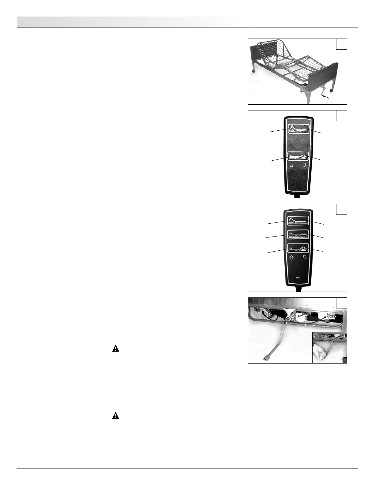
FULL-ELECTRIC BED OPERATION
NOTE– Full-electric beds use a six-function pendant for all operation.
1. Make sure the pendant is properly plugged into the control box and the power cord is
plugged into the wall outlet. Press desired function button in pendant and operate
each function from beginning to end and back again, as instructed below. They
should operate smoothly, without sticking or hesitating.
2. If problems arise, check all electrical connections and mechanical hook ups.
3. To raise the entire height of full-electric beds, press the "BED UP" button on the
hand pendant. To lower the height, press the "BED DOWN" button
(Figure 46).
4. To raise the head section of full-electric beds, press the "HEAD UP" button on the hand
pendant. To lower the head section, press the "HEAD DOWN" button.
5. To raise the foot section of full-electric beds, press the "FOOT UP" button on the hand
pendant. To lower the foot section, press the "FOOT DOWN" button.
LOCKING/UNLOCKING CASTERS
1. If two locking casters are not included with your bed, contact your local Sunrise
Medical dealer.
2. To engage the two wheel locks, push wheel locking tab down until it locks into place.
3. To disengage the wheel locks, push wheel locking tab up until it is released from the
locked position.
WARNING
RISK OF INJURY. Always keep wheels locked during transfers. Check wheel locks
for correct locking operation before each use.
EMERGENCY CRANK FOR SEMI AND FULL ELECTRIC BEDS
Semi-electric and full-electric beds are equipped with an emergency crank. In the event of
power failure or motor failure, you can still operate any of the bed functions by turning the
motor shaft or the center shaft with the emergency crank
(Figure 47).
WARNING
POSSIBLE INJURY. Unplug power cord from wall outlet before using emergency
crank. Injury could result if power resumes while cranking.
Operation
13
English
HEAD UP
FOOT UP
HEAD DOWN
FOOT DOWN
HEAD UP
FOOT UP
HEAD DOWN
BED UP
BED DOWN
FOOT DOWN
44
45
46
47
Crank 2
Page 14
MAINTENANCE
WARNING
POSSIBLE INJURY or damage. While the bed is in use, route the cord away from
any moving parts, sharp edges or sources of heat. Ensure the cord does not present a trip hazard for users or caregivers. When the bed is not in use, disconnect
the cord and store separately.
WARNING
POSSIBLE SHOCK HAZARD. Unplug power cord from wall outlet before performing
any maintenance or service.
We recommend professional servicing by a Sunrise Medical dealer at least once every three
years, depending on the amount of daily use, or with each new user. The dealer should perform the following maintenance:
1. Check for wear on center shaft and drive pins.
2. Inspect head/foot pull tube mounting hardware for bends, wear or damage.
3. Inspect for damage to power cord and pendant cord.
4. Check spring fabric and replace any missing or bent links.
5. Inspect bed end panels and trim for holes and sharp edges.
6. Check casters and wheel locks to ensure they operate properly.
7. Inspect head and foot spring welds for stress cracks and fasteners for wear.
8. Check to make sure mounting hardware is tight.
9. Inspect center mounting hooks and rivets to make sure they are not sheared off or bent.
10. Inspect cables for wear.
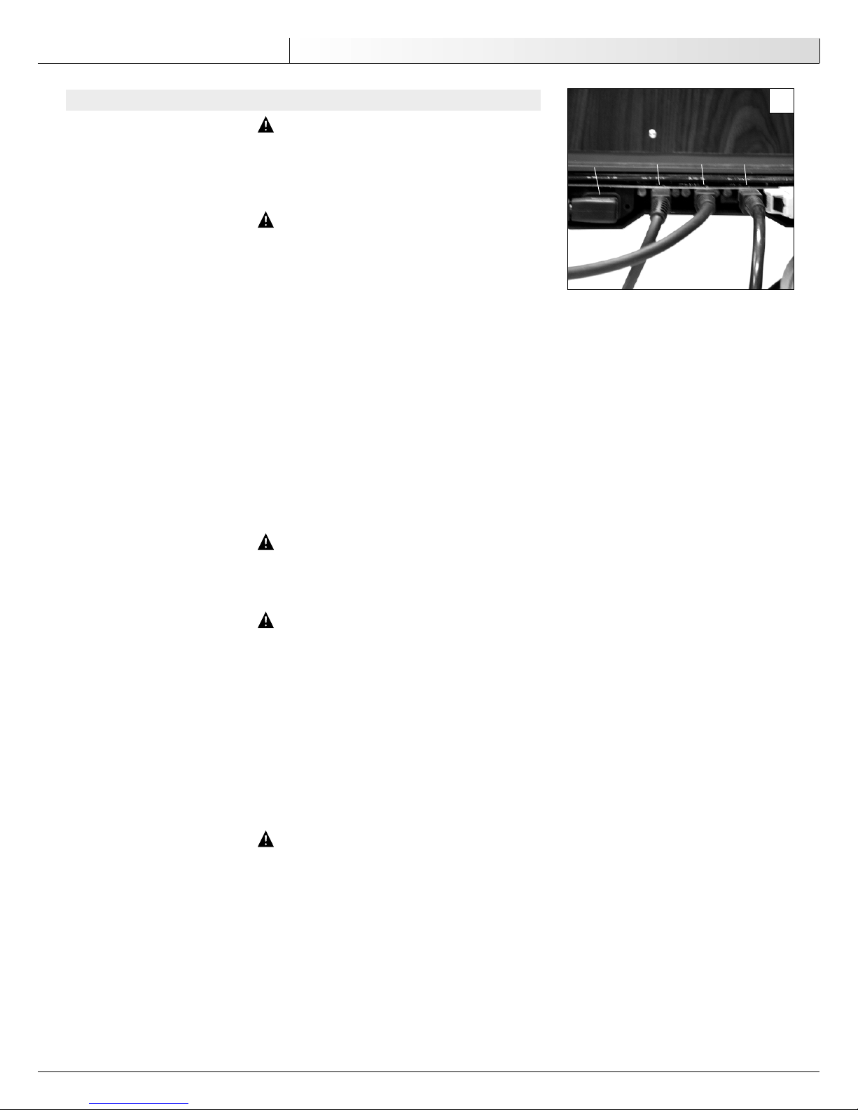
INSTALLING CONNECTORS INTO CONTROL BOX
WARNING
POSSIBLE INJURY OR DAMAGE. When installing connectors into the control box,
make sure the unit is plugged in and the locking tab is facing downward. Do not
force the connector into the control box.
WARNING
POSSIBLE SHOCK HAZARD. The motor control box does not contain serviceable parts.
Unplug the bed if there is a malfunction. Refer servicing to qualified personnel.
NOTE– Depending on the bed model, the control box will have two sockets (head motor and
foot motor) or three sockets (head motor, foot motor and hi/lo motor) (
Figure 48).
1. With the locking tab facing downward, push the connector into the appropriate socket marked on the control box until a click is heard.
2. To remove the connector, push down on the locking tab and pull the connector away
from the control box.
2. Recheck all connections on control box, making sure all motors are plugged into the
correct sockets.
4. Plug the control box power cord into a properly grounded 110-volt, 60 cycle wall outlet.
WARNING
POSSIBLE SHOCK HAZARD. Injury may result from improper routing of the power
cord. Please ensure that the power cord is routed according to the instructions.
14
English
Maintenance
POWER
FOOT HI/LO HEAD
48
Page 15
CLEANING
WARNING
POSSIBLE SHOCK HAZARD. Electric beds only: Always disconnect electrical power
cord from wall outlet before cleaning with liquids or sprays.
Use a mild solution of warm water and an antiseptic cleaner such as LYSOL to wipe away
dust, films, food and fluids. Read and follow label instructions on all cleaning solutions.
CAUTION– POSSIBLE DAMAGE TO ELECTRICAL PARTS. Use only a damp, well wrung-out
cloth to wipe off the motors, motor control box or any electrical component. Excess water in or on electrical parts could cause damage to these
components.
You can keep the woodgrain bed ends attractive by cleaning occasionally with furniture polish or a little lemon oil.
Cleaning / Specifications
15
English
Model Hi/Lo Overall Bed Split Springs Split Springs
No. Range Length Width to Head End to Foot End
IC-5410 15 3/4"–23 1/4" 88" 36" 43" 45"
IC-5310 15 3/4–24 1/2" 88" 36" 43" 45"
IC-5210 15 1/2"–24 1/2" 88" 36" 43" 45"
IC-5110 15" 1/2 88" 36" 43" 45"
IC-5307 16–24"1/4" 88" 36" 43" 45"
IC-5207 15 1/2"–24 1/4" 88" 36" 43" 45"
IC-5107 15 1/4" 88" 36" 43" 45"
Note– Dimensions may vary by 1/2"
SPECIFICATIONS
Page 16

16
English
Troubleshooting
PROBLEM
Nothing happens when button is
pressed on pendant (electric beds).
The back or knee section will not raise
or lower even though you turn the
crank or operate the motor for that
function. (Motor DOES operate.)
Only the headboard or footboard raises
when Hi/Lo adjustment is made (either
manual or electric).
The head or foot of the bed is always
higher than the other end of the bed.
POSSIBLE CAUSE
1. Bed is not plugged in.
2. Blown fuse or tripped circuit breaker in
your home’s circuit box.
3. Pendant is not plugged in at motor
control box.
4. Damaged or defective pendant or power
cord.
1. Internal problems with the drive screw
mechanism. It may only need cleaning
and lubrication, or it could be damaged
or worn.
1. Center drive tube ends are not properly
engaged with pins at each end.
2. The pin in the middle of the center
drive tube has fallen out, allowing tube
to collapse and disengage.
3. One or more of the pins in the center
drive have broken.
4. Damaged mechanism inside the bed
end.
1. The bed ends were not leveled when
bed was assembled.
WHAT TO DO
1. Plug power cord into outlet.
2. Check fuse or circuit breaker.
3. Check to be sure pendant is properly
and securely plugged in.
4. Call your Sunrise Medical supplier for
service and repair.
1. Call your Sunrise Medical supplier for
service and repair.
1. Check both ends of drive tube for proper engagement with pins.
2. Replace pin and reassemble center drive
tube onto shaft ends.
3. Call your Sunrise Medical supplier for
service and repair.
4. Call your Sunrise Medical supplier for
service and repair.
1. See instructions to level the bed.
TROUBLESHOOTING
Page 17

Important: Warnings for Accessories
17
English
IMPORTANT WARNING FOR ACCESSORIES
WARNING
POSSIBLE INJURY. Injury may result from improper use of bed accessories
(patient restraints, side rails, trapeze devices, etc.). Consult the accessory manufacturer for proper use instructions.
OXYGEN EQUIPMENT
WARNING
POSSIBLE FIRE HAZARD. This bed is suitable for use with oxygen administering
equipment of the nasal type and mask type. The use of any other type of oxygen
administering equipment can result in a fire.
WARNING
POSSIBLE INJURY. When using nasal or masked type oxygen administering equipment, the oxygen tubing must be routed and secured properly so that it does not
become entangled and/or severed during operation of the bed.
MATTRESSES
WARNING
RISK OF SERIOUS INJURY OR DEATH. Follow guidelines in User's Manual. Improper
mattresses can expose patient to risk of suffocation if head becomes trapped
between mattress and side rail or frame.
WARNING
RISK OF SERIOUS INJURY OR DEATH. Use a mattress long enough so that the gap
between the mattress and the headboard or footboard is small enough to prevent
a patient from getting his or her head between the mattress and the headboard
or footboard and possibly suffocating.
WARNING
RISK OF SERIOUS INJURY. Use a mattress that is properly sized to fit the mattress
deck and will remain centered on the mattress deck.
SIDE RAILS
WARNING
RISK OF SERIOUS INJURY. When using side rails, only use side rails that can be
positioned so that the gap between the side rails is large enough that the trunk
and hips can easily pass through it. Make sure raising the bed, head section or
foot section does not create any of the previously described gaps.
WARNING
RISK OF SERIOUS INJURY OR DEATH. If side rail is used, follow guidelines in rail
User's Manual. Use of side rail can expose patient to risk of suffocation if head
becomes trapped between mattress and side rail.
WARNING
POSSIBLE INJURY. Make sure side rails are secured properly before using bed.
WARNING
RISK OF SERIOUS INJURY. Individuals with physical limitations who cannot prevent themselves from rolling or climbing out of the bed may require other means
of safe positioning.
WARNING
POSSIBLE DAMAGE OR INJURY. Do not use the side rails as handles when moving
the bed.
Page 18

18
English
Important: Warnings for Accessories
WARNING
POSSIBLE DAMAGE OR INJURY. Side rails do not fall within any weight limitations
and may be damaged if excessive pressure is placed on them. Side rails are for
the purpose of aiding in turning and repositioning within the bed and are not
intended to be used for restraint purposes.
WARNING
RISK OF SERIOUS INJURY OR DEATH. When using side rails, use a mattress thick
enough and wide enough so that the gap between the top of the mattress and the
bottom of the side rails and the gap between the side of the mattress and the
side rails is small enough to prevent a patient from getting his or her head or
neck between the mattress and the side rail. Assure that articulating the bed,
head section or foot section does not create any hazardous gaps. Failure to do so
could result in injury or possible suffocation.
WARNING
RISK OF SERIOUS INJURY OR DEATH. When using side rails, only use side rails that
can be positioned so that the gap between the headboard or foot board and the
side rails is small enough to prevent a patient from getting his or her head or
neck between the mattress and the side rail or large enough that the trunk and
hips can easily pass through it. Assure that articulating the bed, head section or
foot section does not create any hazardous gaps. Failure to do so could result in
injury or possible suffocation.
WARNING
RISK OF SERIOUS INJURY OR DEATH. When using side rails, only use side rails in
which any gaps between the rail body members are small enough to prevent a
patient from getting his or her head or neck inside the rail body. Failure to do so
could result in injury or possible suffocation.
WARNING
RISK OF SERIOUS INJURY. When using multiple side rails on one or both sides of
the bed, only use side rails that can be positioned so that the gap between the
side rails is large enough that the trunk and hips can easily pass through it.
Assure that articulating the bed head section or foot section does not create any
hazardous gaps.
OVERBED TABLES
WARNING
POSSIBLE DAMAGE OR INJURY. Be alert of hi/lo adjustment of overbed table when
raising bed.
TRAPEZE
WARNING
POSSIBLE DAMAGE OR INJURY. Position trapeze unit as close to the center of the
bed as possible. Only use trapeze units to assist patients in repositioning or
transferring in or out of the bed.
WARNING
RISK OF SERIOUS INJURY. Trapeze units used with the bed are not designed to
hold patient’s total weight. Applying excessive weight may cause unit to fail and
injury to occur.
Page 19

Warranty
19
English
WARRANTY
SUNRISE MEDICAL PRODUCT ASSURANCE WARRANTY PROGRAM
Sunrise Medical products are guaranteed for a period of 24 months from the date of delivery
against defects in materials and workmanship under normal use and service.
Technical Support Hotline: (800) 333-4000
Welds on beds are covered under warranty for the lifetime of the original purchaser.
This warranty does not apply to damage or defects caused by misuse, incorrect handling, or
set-up by a non-authorized dealer. Damage caused by use in unsuitable environmental conditions or failure to maintain the product in accordance with user and service instructions
is not covered. Any alteration, modification, or repair unless performed by, or authorized in
writing by Sunrise Medical will void this warranty.
PARTS
Sunrise Medical's obligation under this warranty is limited to supplying replacement parts,
servicing, or replacing, at its option, any product which is found by Sunrise Medical to be
defective.
Warranty replacement parts are covered by the terms of this warranty until the product's
original warranty period expires.
When requested by Sunrise Medical, parts must be returned for inspection at the customer's
expense. Credit will be issued only after inspection.
This warranty does not include any charges associated with labor or shipping of replacement
parts or installation or repair of any such product. The sole responsibility of Sunrise Medical
and your only remedy under this warranty is limited to such repair and/or replacement.
Page 20

20
Franç ais
Introduction
INTRODUCTION
SUNRISE À L’ÉCOUTE
Nous vous remercions d’avoir choisi un lit Sunrise Medical Nous sommes à l’écoute de vos
questions et commentaires sur ce manuel, la sécurité et la fiabilité de votre lit et le service
offert par votre fournisseur Sunrise. N’hésitez pas à nous écrire ou à nous appeler à
l’adresse et au numéro de téléphone ci-dessous :
SUNRISE MEDICAL
Service à la clientèle
7477 East Dry Creek Parkway
Longmont, CO 80503, États-Unis
(303) 218-4600 or (800) 333-4000
RÉPONSES À VOS QUESTIONS
Votre fournisseur agréé est la personne qui connaît le mieux les caractéristiques de votre lit
et peut répondre à la plupart de vos questions sur la sécurité, l’usage et l’entretien. Pour
référence, veuillez remplir la liste de renseignements, ci-après :
Fournisseur : ________________________________________________________________
Adresse : __________________________________________________________________
Téléphone : ________________________________________________________________
Nº de série : ________________________________________________________________
Date d’achat : ______________________________________________________________
Ce manuel fournit des instructions importantes sur la sécurité et l’entretien. Veuillez le lire
attentivement avant d’utiliser le lit de soins à domicile et le consulter chaque fois qu’il est
nécessaire pour une utilisation sûre et efficace.
Pour toutes questions sur les conditions d’utilisation en toute sécurité et/ou le montage,
l’entretien ou les caractéristiques du lit, contactez le Service à la clientèle au 800-3334000, 303-218-4600 ou du Canada au 800-263-339. Veuillez avoir les numéros de modèle
et de série du produit à portée de la main.
Pour tous les travaux d’entretien et de réparation, n’oubliez pas que votre revendeur agréé
Surnrise Medical peut vous fournir l’assistance dont vous avez besoin.
Conservez ce manuel comme référence dans un endroit sûr.
Page 21

Table des Matiè res
21
Franç ais
TABLE DES MATIÈRES
INTRODUCTION........................................................................................ 20
TABLE DES MATIÈRES ............................................................................... 21
AVERTISSEMENTS IMPORTANTS .................................................................. 22
CAPACITÉ DU LIT..................................................................................... 23
PRÉPARATON........................................................................................... 23
ASSEMBLAGE........................................................................................... 24
Assemblage du lit manuel ...................................................................... 24
Assemblage du lit semi-électrique ........................................................... 26
Assemblage du lit électrique 3 positions .................................................. 28
FONCTIONNEMENT ................................................................................... 30
Fonctionnement du lit manuel ................................................................ 30
Fonctionnement du lit semi-électrique ..................................................... 30
Fonctionnement du lit électrique 3 positions ............................................ 31
Roulettes avec mécanisme de blocage/déblocage ...................................... 31
ENTRETIEN.............................................................................................. 32
NETTOYAGE / SPÉCIFICATIONS................................................................... 33
GUIDE DES PANNES.................................................................................. 34
AVERTISSEMENTS IMPORTANTS CONCERNANT LES ACCESSOIRES .................... 35
GARANTIE............................................................................................... 37
Page 22

22
Franç ais
Avertissements Importants
AVERTISSEMENTS IMPORTANTS
(Voir pages 35 & 36 Avertissements importants concernant les accessoires)
AVERTISSEMENT
RISQUE DE BLESSURE GRAVE OU MORTELLE Le cordon d’alimentation du lit est
doté d’une fiche à 3 broches de mise à la terre. N’essayez pas de modifier ce dispositif de sécurité en utilisant les 3 broches sur un adaptateur à 2 broches. Si
nécessaire, demandez à un électricien de contrôler la fiabilité de la prise de
terre. Tout manquement à cette consigne de sécurité expose au risque de choc
électrique ou d’électrocution.
AVERTISSEMENT
RISQUE DE BLESSURE GRAVE. Lorsque vous faites fonctionner le lit, veillez à ce
que l’occupant soit à l’intérieur du périmètre du lit et qu’aucun membre ne
dépasse sur les côtés ou entre les barres.
AVERTISSEMENT
RISQUE DE BLESSURE GRAVE. Surveillez constamment les enfants ou les personnes
à haut risque qui occupent le lit ou se trouvent près du lit.
AVERTISSEMENT
RISQUE DE BLESSURE GRAVE. Une interférence électromagnétique (EMI) peut agir
sur l’appareillage électronique. Faites preuve de prudence en utilisant des émetteurs-récepteurs portables près du lit électrique. En cas de mouvement imprévu
du lit occasionné par une interférence électromagnétique, débranchez immédiatement le lit électrique. Laissez débranché pendant la transmission pour éviter tout
risque de blessure.
AVERTISSEMENT
ENDOMMAGEMENT OU BLESSURE POSSIBLE. Le lit de soins à domicile n’est pas
conçu pour servir de moyen de transport. Utilisez un dispositif de transport agréé
pour transporter un patient.
AVERTISSEMENT
ENDOMMAGEMENT OU BLESSURE POSSIBLE. Le lit de soins à domicile est conçu
pour être utilisé uniquement dans le cadre de soins à domicile et non dans des
maisons de retraite ou des hôpitaux.
AVERTISSEMENT
ENDOMMAGEMENT OU BLESSURE POSSIBLE. N’autorisez en aucun cas l’occupation
du lit par plus d’une personne.
AVERTISSEMENT
ENDOMMAGEMENT OU BLESSURE POSSIBLE. Répartissez le poids du corps de la
personne uniformément sur la surface du lit. Veillez à ce que le poids du corps ne
repose pas uniquement sur la section pied ou la section tête, pour ne pas endommager le lit.
AVERTISSEMENT
RISQUE DE BLESSURE GRAVE. Éloignez le cordon d’alimentation des surfaces chaudes.
AVERTISSEMENT
ENDOMMAGEMENT OU BLESSURE POSSIBLE. N’utilisez pas le lit à l’extérieur.
CONSERVEZ CES INSTRUCTIONS.
Page 23

Pré paration
23
Franç ais
CAPACITÉ DU LIT
Le lit de soins à domicile a une capacité de 204 kg (450 livres) répartis uniformément sur
la surface. Cette capacité comprend le poids de l’occupant, le sommier, la literie, les accessoires et l’appareillage médical utilisés. Tout dépassement de la limite de poids annule la
garantie.
PRÉPARATON
Assurez-vous qu’aucune composante du lit n’a été endommagée lors de l’expédition. Vérifiez
soigneusement toutes les pièces et assurez-vous qu’elles ne présentent ni rayure ni autre
dommage apparent. Si l’endommagement est évident, contactez votre revendeur local
Sunrise Medical.
AVERTISSEMENT
Avant d’assembler le lit, vérifiez qu’aucune pièce n’a été endommagée pendant
l’expédition. Si l’endommagement est évident, n’utilisez pas le lit. Contactez
immédiatement une personne qualifiée.
ATTENTION– Ne branchez pas le lit et n’utilisez pas les commandes du lit avant l’assem-
blage complet. L’endommagement des composantes du lit ou des blessures
pourraient en résulter.
Le lit est emballé dans trois boîtes en carton :
1. Panneaux du lit
(Figure 1)
•Panneau de tête.
•Panneau de pied
•Barre de connexion de réglage de la hauteur (non fournie avec les modèles à hauteur fixe ou à deux manivelles).
•Quatre roulettes (deux avec mécanisme de blocage et deux sans mécanisme de blocage)
2. Pied à ressort
(Figure 2)
•Pied à ressort (les lits électriques comportent un pendant, un boîtier de commande
et un cordon d’alimentation)
•Manivelle d’urgence (uniquement pour les lits électriques)
3. Tête à ressort
(Figure 3)
Pour les lits électriques, vérifiez que le cordon d’alimentation et la fiche ne sont pas
endommagés. Vérifiez que les connecteurs du boîtier de commande ne sont pas endommagés et que les fiches du moteur sont insérées correctement dans le boîtier de commande.
Voir
(Figure 48) dans la section Entretien pour l’installation correcte des connecteurs dans
le boîtier de commande.
AVERTISSEMENT
RISQUE DE BLESSURE N’utilisez pas le lit si le cordon d’alimentation ou la fiche sont
endommagés. Faites appel à un technicien agréé pour effectuer les réparations.
N° de Section Section Panneaux
modèle Type de lit Tête Pied du lit
IC-5410 Intégralement électrique IC-5000 IC-5490 IC-5401
IC-5310 Semi-électrique avec une seule manivelle de réglage de la hauteur IC-5000 IC-5890 IC-5301
IC-5210 Semi-électrique avec deux manivelles de réglage de la hauteur IC-5000 IC-5890 IC-5200
IC-5110 Semi-électrique avec hauteur fixe IC-5000 IC-5890 IC-5100
IC-5307 Manuel avec une seule manivelle de réglage de la hauteur IC-5000 IC-5770 IC-5301
IC-5207 Manuel avec deux manivelles de réglage de la hauteur IC-5000 IC-5770 IC-5200
IC-5107 Manuel avec hauteur fixe IC-5000 IC-5770 IC-5100
Numéro des pièces des composantes principales du lit
1
2
3
Page 24

24
Franç ais
Assemblage
ASSEMBLAGE
ASSEMBLAGE DU LIT MANUEL
AVERTISSEMENT
Après tout réglage, réparation ou entretien et avant d’utiliser le lit, vérifiez que
tous les dispositifs de fixation sont bien serrés.
ATTENTION– N’utilisez pas les commandes du lit avant l’assemblage complet. Un endom-
magement des composantes du lit ou des blessures pourraient en résulter.
Connexion des sections tête et pied
1. Disposez la tête et le pied de lit de manière qu’ils forment un angle droit (90°). La
tête de lit doit reposer sur le côté à votre gauche avec le dispositif d’accrochage central à votre droite
(Figure 4). Le pied de lit (avec les manivelles) doit être à votre
droite avec le tube de la tête à ressort vers le haut et les rivets d’accrochage central
positionnés à gauche.
2. Insérez le dispositif d’accrochage de la tête de lit dans le rivet du pied de lit
(Figure 5).
REMARQUE– Il peut être nécessaire de soulever légèrement la tête ou le pied de lit pour
bien mettre en place le dispositif d’accrochage et le rivet.
3. Faites pivoter la section arrière de 90 degrés pour que le châssis soit en position horizontale
(Figure 6).
Connexion des éléments structuraux des sections tête et pied
1. Tournez la manivelle du pied dans le sens horaire afin de relever le pied de lit (voir
Fonctionnement du lit manuel)
(Figure 7).
2. Accrochez ensemble tous les maillons à la surface du sommier
(Figure 8).
Connexion du tube d’entraînement de la tête à ressort
1. Déconnectez l’ensemble du tube d’entraînement de la tête situé sur le châssis latéral
du pied à ressort en enlevant la cheville d’attache, l’œillet et la rondelle de l’axe à
épaulement
(Figure 9).
2. Tirez le tube intérieur d’entraînement jusqu’à ce que le bouton de cran s’enclenche
dans le trou d’ajustement du tube intérieur d’entraînement. Vérifiez que le bouton de
cran fait saillie par rapport au trou d’ajustement du tube d’entraînement qui a été
tiré.
(Figure 10) Le bras du tube d’entraînement est aligné sur l’encoche du bras élé-
vateur.
3. Attachez l’extrémité du tube d’entraînement au bras élévateur de la tête à ressort en
insérant l’axe à épaulement dans l’encoche du bras élévateur. Reconnectez l’œillet et
la rondelle et serrez avec la cheville d’attache
(Figure 11).
4. Après avoir assemblé le châssis, mettez le lit en position horizontale.
4
6
8
9
7
5
Page 25

Assemblage
25
Franç ais
Assemblage des panneaux du lit
REMARQUE– Le panneau de tête est plus haut que le panneau de pied.
1. Placez le panneau de tête à côté de la section tête du lit.
2. Soulevez la tête de lit et insérez les rivets du châssis dans le dispositif d’accrochage
du panneau de tête
(Figure 12). Pour faciliter l’insertion des rivets dans le dispositif
d’accrochage inclinez le panneau de tête légèrement.
3. De la même manière, soulevez la section pied du lit et insérez les rivets du châssis
dans le dispositif d’accrochage du panneau de pied.
AVERTISSEMENT
Avant d’utiliser le lit, vérifiez que les sections de tête et de pied sont bien fixées
aux panneaux de tête et de pied.
Installation des roulettes
REMARQUE– Pour assurer une stabilité de blocage maximal, assemblez les deux roulettes
munies d’un dispositif de blocage en les disposant diagonalement l’une par
rapport à l’autre aux extrémités opposées du lit.
Installez les quatre roulettes en soulevant les panneaux du lit et en introduisant la tige
dans le logement de la roulette de chaque pied du lit.
(Figure 13)
Assemblage de la barre de connexion de réglage de la hauteur
REMARQUE– Cette section ne s’applique pas aux modèles à hauteur fixe ou à deux
manivelles.
REMARQUE– La barre de connexion comporte deux sections : la section intérieure de la
barre est dotée d’un bouton de cran, et la section extérieure de la barre comporte deux trous de positionnement et un trou pour la position entreposage.
1. Enlevez les embouts en plastique de chaque extrémité de la barre de connexion.
2. Appuyez sur le bouton de cran de la section intérieure de la barre et insérez cette
dernière dans la section extérieure de la barre. Faites glisser la section intérieure de
la barre et bloquez-la en enclenchant le bouton de cran dans le premier trou de positionnement.
3. La barre de connexion est montée directement dans l’arbre moteur d’entraînement de
la boîte d’engrenage côté tête et côté pied
(Figures 14 et 15).
10
11
12
13
14
15
Page 26

26
Franç ais
Assemblage
ASSEMBLAGE DU LIT SEMI-ÉLECTRIQUE
AVERTISSEMENT
Après tout réglage, réparation ou entretien et avant d’utiliser le lit, vérifiez que
tous les dispositifs de fixation sont bien serrés.
ATTENTION– N’utilisez pas les commandes du lit avant l’assemblage complet. Un endom-
magement des composantes du lit ou des blessures pourraient en résulter.
Connexion des sections tête et pied
1. Disposez la tête et le pied de lit de manière qu’ils forment un angle droit (90°). La
tête de lit doit reposer sur le côté à votre gauche avec le dispositif d’accrochage central à votre droite
(Figure 16). Le pied de lit (avec moteur) doit être à votre droite
avec le tube de la tête à ressort vers le haut et les rivets d’accrochage central positionnés à gauche. Pour les pieds de lit à commande électrique, le moteur doit être à
votre droite, et pour les pieds de lit à commande manuelle, la manivelle est à votre
droite.
2. Insérez le dispositif d’accrochage de la tête de lit dans le rivet du pied de lit
(Figure 17).
REMARQUE– Il peut être nécessaire de soulever légèrement la tête ou le pied de lit pour
bien mettre en place le dispositif d’accrochage et le rivet.
3. Faites pivoter la section arrière de 90 degrés pour que le châssis soit en position horizontale.
(Figure 18).
Connexion des éléments structuraux des sections de pied et de tête
1. Appuyez sur le bouton « Relever le pied » du pendant (voir Fonctionnement du lit
semi-électrique) ou utilisez la manivelle d’urgence pour tourner l’arbre moteur dans le
sens horaire afin de relever le pied de lit
(Figure 19).
2. Accrochez ensemble tous les maillons à la surface du sommier
(Figure 20).
Connexion du tube d’entraînement de la tête à ressort
1. Déconnectez l’ensemble tube d’entraînement de la tête de châssis latéral du pied à
ressort en enlevant la cheville d’attache, l’œillet et la rondelle de l’axe à épaulement
(Figure 21).
2. Tirez l’arbre d’entraînement du tube intérieur jusqu’à ce que le bouton de cran s’enclenche dans le trou d’ajustement du tube d’entraînement extérieur. Vérifiez que le
bouton de cran fait saillie par rapport au trou d’ajustement du tube d’entraînement
tiré.
(Figure 22) Le tube d’entraînement est aligné sur l’encoche du bras élévateur.
3. Attachez l’extrémité du tube d’entraînement au bras élévateur de la tête à ressort en
insérant l’axe à épaulement dans l’encoche du bras élévateur. Reconnectez l’œillet et
la rondelle et serrez avec la cheville d’attache
(Figure 23).
4. Après avoir assemblé le châssis, mettez le lit à plat.
Assemblage des panneaux du lit
REMARQUE– Le panneau de tête est plus haut que le panneau de pied.
1. Placez le panneau de tête à côté de la section tête du lit.
2. Soulevez la tête de lit et insérez les rivets du châssis dans le dispositif d’accrochage
du panneau de tête
(Figure 24). Pour faciliter l’insertion des rivets dans le dispositif
d’accrochage inclinez le panneau de tête légèrement.
3. De la même manière, soulevez la section pied du lit et insérez les rivets du châssis
dans le dispositif d’accrochage du panneau de pied.
AVERTISSEMENT
Avant d’utiliser le lit, vérifiez que les sections de tête et de pied sont bien fixées
aux panneaux de tête et de pied.
16
18
20
21
19
17
Page 27

Assemblage
27
Franç ais
Installation des roulettes
REMARQUE– Pour assurer une stabilité de blocage maximal, assemblez les deux roulettes
munies d’un dispositif de blocage en les disposant diagonalement l’une par
rapport à l’autre aux extrémités opposées du lit.
Installez les quatre roulettes en soulevant les panneaux du lit et en introduisant la tige
dans le logement de la roulette de chaque pied du lit.
(Figure 25)
Assemblage de la barre de connexion de réglage de la hauteur
REMARQUE– Cette section ne s’applique pas aux modèles à hauteur fixe ou à deux
manivelles.
REMARQUE– La barre de connexion comporte deux sections : la section intérieure de la
barre est dotée d’un bouton de cran, et la section extérieure de la barre comporte deux trous de positionnement et un trou pour la position entreposage.
1. Enlevez les embouts en plastique de chaque extrémité de la barre de connexion.
2. Appuyez sur le bouton de cran de la section intérieure de la barre et insérez cette
dernière dans la section extérieure de la barre. Faites glisser la section intérieure de
la barre et bloquez-la en enclenchant le bouton de cran dans le premier trou de positionnement.
3. La barre de connexion est montée directement dans l’arbre moteur d’entraînement de
la boîte d’engrenage côté tête et côté pied
(Figures 26 et 27).
AVERTISSEMENT
ENDOMMAGEMENT OU BLESSURE POSSIBLE. Lorsque l’assemblage du lit est terminé, vérifiez que toutes les composantes sont bien fixées et que toutes les
attaches sont serrées avant de l’utiliser.
AVERTISSEMENT
RISQUE DE BLESSURE Ne laissez pas un lit branché lorsque vous ne l’utilisez pas.
Installation du pendant
Installez le pendant en branchant son connecteur dans la prise correspondante du boîtier
de commande.
REMARQUE– Les lits semi-électriques sont dotés d’un pendant à quatre fonctions pour les
commandes de la tête et du pied.
Nivellement du lit
Pour les lits semi-électriques avec une seule manivelle, tournez la manivelle de réglage de
la hauteur dans le sens antihoraire (voir Fonctionnement du lit semi-électrique). La partie
la plus basse du lit s’immobilisera, mais la partie la plus haute continuera à s’abaisser.
Lorsque les deux panneaux du lit sont à la position la plus basse, le lit est nivelé.
REMARQUE– Si vous éprouvez des difficultés à niveler le lit en constatant qu’une seule
extrémité se lève ou s’abaisse, vérifiez que tous les rivets et les dispositifs
d’accrochage du tube d’entraînement central sont bien enclenchés.
22
23
24
25
26
27
Page 28

ASSEMBLAGE DU LIT ÉLECTRIQUE 3 POSITIONS
AVERTISSEMENT
Après tout réglage, réparation ou entretien et avant d’utiliser le lit, vérifiez que
tous les dispositifs de fixation sont bien serrés.
ATTENTION– N’utilisez pas les commandes du lit avant l’assemblage complet. Un endom-
magement des composantes du lit ou des blessures pourraient en résulter.
Connexion des sections tête et pied
1. Disposez la tête et le pied de lit de manière qu’ils forment un angle droit (90°). La
tête de lit doit reposer sur le côté à votre gauche avec le dispositif d’accrochage central à votre droite
(Figure 28). Le pied de lit (avec moteur) doit être à votre droite
avec le tube de la tête à ressort vers le haut et les rivets d’accrochage central positionnés à gauche.
2. Insérez le dispositif d’accrochage de la tête de lit dans le rivet du pied de lit
(Figure 29).
REMARQUE– Il peut être nécessaire de soulever légèrement la tête ou le pied de lit pour
bien mettre en place le dispositif d’accrochage et le rivet.
3. Faites pivoter la section arrière de 90 degrés pour que le châssis soit en position horizontale.
(Figure 30).
Connexion des éléments structuraux des sections tête et pied
1. Appuyez sur le bouton « Relever le pied » du pendant (voir Fonctionnement du lit
semi-électrique) ou utilisez la manivelle d’urgence pour tourner l’arbre moteur dans le
sens horaire afin de relever le pied de lit
(Figure 31).
2. Accrochez ensemble tous les maillons à la surface du sommier
(Figure 32).
Connexion du tube d’entraînement de la tête à ressort
1. Déconnectez l’ensemble tube d’entraînement de la tête située sur le châssis latéral du
pied à ressort en enlevant la cheville d’attache, l’œillet et la rondelle de l’axe à
épaulement
(Figure 33).
2. Tirez l’arbre d’entraînement du tube intérieur jusqu’à ce que le bouton de cran s’enclenche dans le trou d’ajustement du tube d’entraînement extérieur. Vérifiez que le
bouton de cran fait saillie par rapport au trou d’ajustement du bras d’entraînement
qui a été tiré.
(Figure 34) Le bras du tube d’entraînement est aligné sur l’encoche du
bras élévateur.
3. Attachez l’extrémité du tube d’entraînement au bras élévateur de la tête à ressort en
insérant l’axe à épaulement dans l’encoche du bras élévateur. Reconnectez l’œillet et
la rondelle et serrez avec la cheville d’attache
(Figure 35).
4. Après avoir assemblé le châssis, mettez le lit en position horizontale.
Assemblage des panneaux du lit
REMARQUE– Le panneau de tête est plus haut que le panneau de pied.
1. Placez le panneau de tête à côté de la section tête de lit.
2. Soulevez la tête de lit et insérez les rivets du châssis dans le dispositif d’accrochage
du panneau de tête
(Figure 36). Pour faciliter l’insertion des rivets dans le dispositif
d’accrochage inclinez le panneau de tête légèrement.
3. De la même manière, soulevez la section pied du lit et insérez les rivets du châssis
dans le dispositif d’accrochage du panneau de pied.
AVERTISSEMENT
Avant d’utiliser le lit, vérifiez que la tête et le pied de lit sont bien fixés aux
panneaux de tête et de pied.
28
Franç ais
Assemblage
28
30
32
33
31
29
Page 29

Installation des roulettes
REMARQUE– Pour assurer une stabilité de blocage maximal, assemblez les deux roulettes
munies d’un dispositif de blocage en les disposant diagonalement l’une par
rapport à l’autre aux extrémités opposées du lit.
Installez les quatre roulettes en soulevant les panneaux du lit et en poussant la tige dans
le logement de la roulette de chaque pied de lit.
(Figure 37)
Assemblage de la barre de connexion de réglage de la hauteur
REMARQUE– La barre de connexion comporte deux sections : la section intérieure de la
barre est dotée d’un bouton de cran, et la partie extérieure de la barre a
deux trous de positionnement et un trou pour la position entreposage.
1. Enlevez les embouts en plastique à chaque extrémité de la barre de connexion.
2. Appuyez sur le bouton de cran de la section intérieure de la barre et insérez cette
dernière dans la section extérieure de la barre. Faites glisser la section intérieure de
la barre et bloquez-la en enclenchant le bouton de cran dans le trou de positionnement du milieu.
3. Connectez une extrémité de la barre de connexion de réglage de la hauteur à la boîte
d’engrenage côté tête
(Figure 38). Connectez l’autre extrémité à l’arbre moteur de
réglage de la hauteur
(Figure 39). Connectez l’arbre d’entraînement de la boîte d’en-
grenage côté pied au connecteur à ressort de l’arbre moteur de réglage de la hauteur
(Figures 40 & 41).
4. Dégagez la barre de connexion de réglage de la hauteur du connecteur à ressort en
appuyant dessus et en la tournant dans le sens horaire.
AVERTISSEMENT
ENDOMMAGEMENT OU BLESSURE POSSIBLE. Lorsque l’assemblage du lit est terminé, vérifiez que toutes les composantes sont bien fixées et que toutes les
attaches sont serrées avant de l’utiliser.
AVERTISSEMENT
RISQUE DE BLESSURE Ne laissez pas un lit branché lorsque vous ne l’utilisez pas.
Installation du pendant
Uniquement pour les modèles de lit électrique : Installez le pendant en branchant le fil
connecteur dans la prise correspondante du boîtier de commande.
REMARQUE– Tous les lits intégralement électriques sont dotés d’un pendant à six fonc-
tions permettant de contrôler toutes les opérations.
Nivellement du lit
Branchez le cordon d’alimentation du lit dans une prise. Maintenez appuyé le bouton «
RELEVER LE LIT » du pendant jusqu’à ce que le moteur de réglage de la hauteur s’arrête
automatiquement (voir Fonctionnement d’un lit électrique 3 positions). Puis maintenez
appuyé le bouton « ABAISSER LE LIT » du pendant jusqu'à ce que le moteur de réglage de
la hauteur s’arrête. Le lit est nivelé et réglé à la position la plus basse et offrant le maximum de sécurité.
REMARQUE– Si vous éprouvez des difficultés à niveler le lit en constatant qu’une seule
extrémité se lève ou s’abaisse, vérifiez que tous les rivets et les dispositifs
d’accrochage du tube d’entraînement central sont bien enclenchés.
AVERTISSEMENT
RISQUE DE BLESSURE. Ne laissez pas un lit branché lorsque vous ne l’utilisez pas.
Assemblage
29
Franç ais
34
35
36
37
38
39
Page 30

FONCTIONNEMENT
AVERTISSEMENT
Endommagement ou BLESSURE POSSIBLE. Les lits électriques sont conçus pour un
circuit d’une puissance nominale de 120 volts et dotés d’une prise comme celle illustrée Figure 42. Vérifiez que l’unité est connectée à une prise de courant ayant la
même configuration que la prise du lit. N’utilisez aucun adaptateur avec cette prise.
RISQUE DE BLESSURE Avant de régler le lit, vérifiez qu’aucun objet ne se trouve
sous le lit ou à proximité du lit. Éloignez les enfants et les animaux du lit pour
éviter les blessures.
La section tête peut être ajustée selon n’importe quel angle, mise à l’horizontale pour permettre de dormir ou relevée pour s’asseoir, manger, lire ou regarder la télévision.
La section genoux peut être réglée selon n’importe quel angle, de la position horizontale à
la position la plus haute. La modification de l’angle influe sur la circulation sanguine et les
points de compression des membres inférieurs améliorant ainsi le confort de l’utilisateur.
Le lit complet peut être ajusté de la position la plus basse pour y accéder et en sortir en
toute sécurité, à la position la plus haute, pour faciliter l’administration de soins au
patient. Il est beaucoup plus facile de changer les draps, les vêtements, de laver et d’alimenter le patient lorsque le lit est plus élevé.
AVERTISSEMENT
RISQUE DE BLESSURE. Mettez le lit à la position la plus basse, sauf au moment de
l’administration des soins (toilette, changement de vêtements, etc.). Accéder ou
sortir d’un lit élevé expose au risque de chute ou de blessure.
RISQUE DE BLESSURE GRAVE OU MORTELLE. N’utilisez aucun liquide dans le lit
électrique ou à proximité. En cas de déversement, débranchez immédiatement le
lit. Essuyez le liquide et laissez sécher complètement avant de réutiliser le lit
électrique. Tout manquement à cette consigne de sécurité expose au risque de
choc électrique ou d’électrocution.
ENDOMMAGEMENT OU BLESSURE POSSIBLE. Lorsque vous faites fonctionner le lit,
veillez à ce que rien ne fasse obstacle aux parties mobiles (couverture, draps,
couverture ou coussin chauffants, tubulure ou appareils munis d’un cordon électrique pouvant s’enchevêtrer autour du lit, des côtés ou des pieds du lit).
FONCTIONNEMENT DU LIT MANUEL
1. Tournez les manivelles correspondant à chaque fonction du lit, du début à la fin du
réglage et vice versa comme indiqué ci-dessous. L’utilisation de la manivelle et des
fonctions doit s’effectuer librement et en douceur.
2. En cas de problème, contrôlez les mécanismes d’accrochage.
3. Le lit à hauteur fixe (IC-5107) dispose de fonctions tête et pied, mais la hauteur du
lit ne peut pas être réglée.
4. Afin de relever au maximum un lit avec une seule manivelle de réglage de la hauteur
(IC-5307) tourner la manivelle 2 dans le sens horaire. Pour abaisser le lit, tournez la
manivelle 2 dans le sens antihoraire
(Figure 43).
5. Pour élever séparément la hauteur de la tête et du pied d’un lit à deux manivelles de
réglage de la hauteur (IC-5207), insérez la manivelle 4 (non illustré) dans le pied ou
la tête de lit et tournez dans le sens horaire. Pour abaisser le lit tournez la manivelle
4 (non illustré) dans le sens antihoraire.
6. Pour élever la section tête de tous les lits manuels, tournez la manivelle 1 dans le
sens horaire. Pour abaisser le lit, tournez la manivelle 1 dans le sens antihoraire.
7. Pour élever la section pied de tous les lits manuels, tournez la manivelle 3 dans le sens
horaire. Pour abaisser cette section tournez la manivelle 3 dans le sens antihoraire.
FONCTIONNEMENT DU LIT SEMI-ÉLECTRIQUE
REMARQUE– Les lits semi-électriques sont dotés d’un pendant à quatre fonctions pour les
commandes de la tête et du pied. Les lits à une manivelle et à deux manivelles fonctionnent avec une manivelle de réglage de la hauteur; les lits à
hauteur fixe ne disposent pas de la fonction réglage de la hauteur.
30
Franç ais
Fonctionnement
40
41
42
43
Manivelle 2
Manivelle 3
Manivelle 1
Prise de mise
à la terre
Broche de mise
à la terre
Page 31

1. Vérifiez que le pendant est correctement branché au boîtier de commande et que le cordon d’alimentation est branché à la prise murale. Appuyez sur le bouton du pendant correspondant à la fonction souhaitée et activez chaque fonction du début à la fin et viceversa comme indiqué ci-dessous. L’activation des fonctions doit s’effectuer en douceur.
2. En cas de problème, contrôlez toutes les connexions électriques et les mécanismes
d’accrochage.
3. Le lit à hauteur fixe (IC-5110) dispose de fonctions tête et pied, mais la hauteur du
lit ne peut pas être réglée.
4. Pour élever la hauteur d’un lit à une seule manivelle de réglage de la hauteur (IC-
5310) tournez la manivelle 2 dans le sens horaire. Pour abaisser le lit, tournez la
manivelle 2 dans le sens antihoraire
(Figure 44).
5. Afin de relever au maximum séparément la tête et le pied d’un lit à deux manivelles
de réglage de la hauteur (IC-5307), insérez la manivelle 4 (non illustré) dans le pied
ou la tête de lit et tournez dans le sens horaire «Pour abaisser le lit, tournez la
manivelle dans le sens antihoraire.
6. Afin de relever la tête de tous les lits semi-électriques, appuyez sur le bouton «
Relever la tête » du pendant. Pour abaisser la tête de lit, appuyez sur le bouton «
Abaisser la tête »
(Figure 45).
7. Afin de relever le pied de tous les lits semi-électriques, appuyez sur le bouton «
RELEVER LE PIED » du pendant. Pour abaisser le pied de lit, appuyez sur le bouton «
ABAISSER LE PIED »
FONCTIONNEMENT DU LIT ÉLECTRIQUE 3 POSITIONS
REMARQUE– Toutes les commandes pour les lits électriques s’effectuent au moyen d’un
pendant à six fonctions.
1. Vérifiez que le pendant est correctement branché au boîtier de commande et que le cordon d’alimentation est branché à la prise murale. Appuyez sur le bouton du pendant correspondant à la fonction souhaitée et activez chaque fonction du début à la fin et viceversa comme indiqué ci-dessous. L’activation des fonctions doit s’effectuer en douceur.
2. En cas de problème, contrôlez toutes les connexions électriques et les mécanismes
d’accrochage.
3. Afin de relever au maximum les lits intégralement électriques, appuyez sur le bouton
« RELEVER LE LIT » du pendant. Pour abaisser le lit, appuyez sur le bouton « ABAISSER LE LIT »
(Figure 46).
4. Afin de relever la section tête des lits intégralement électriques, appuyez sur le bouton « RELEVER LA TÊTE » du pendant. Pour abaisser la section tête, appuyez sur le
bouton « ABAISSER LA TÊTE »
5. Pour relever la section pied des lits intégralement électriques, appuyez sur le bouton
« RELEVER LE PIED » du pendant. Pour abaisser la section pied, appuyez sur le bouton « ABAISSER LE PIED ».
ROULETTES AVEC MÉCANISME DE BLOCAGE/DÉBLOCAGE
1. Si deux roulettes avec mécanisme de blocage ne sont pas fournies avec le lit, contactez votre fournisseur Sunrise Medical.
2. Pour bloquer les deux roues, appuyez sur le dispositif de verrouillage des roues
jusqu’à ce qu’il soit enclenché.
3. Pour débloquer les deux roues, tirez sur le dispositif de verrouillage des roues jusqu’à
ce qu’il se dégage.
AVERTISSEMENT
RISQUE DE BLESSURE. Bloquez toujours les roues pendant les transferts. Vérifiez
le mécanisme de blocage avant chaque utilisation.
MANIVELLE DE SECOURS POUR LES LITS SEMI-ÉLECTRIQUES ET ÉLECTRIQUES.
Les lits semi-électriques et électriques sont munis d’une manivelle d’urgence. En cas de panne
de courant ou du moteur, il est toujours possible d’activer toutes les fonctions du lit en tournant l’arbre moteur ou l’arbre central au moyen de la manivelle de secours
(Figure 47).
AVERTISSEMENT
RISQUE DE BLESSURE Débranchez le cordon d’alimentation avant d’utiliser la
manivelle d’urgence. Le rétablissement du courant pendant l’utilisation de la
manivelle peut occasionner des blessures.
Fonctionnement
31
Franç ais
RELEVER LA
TÊTE
RELEVER LE
PIED
ABAISSER
LA TÊTE
ABAISSER
LE PIED
RELEVER LE
LIT
ABAISSER
LE LIT
44
45
46
47
Manivelle 2
RELEVER LA
TÊTE
RELEVER LE
PIED
ABAISSER
LA TÊTE
ABAISSER
LE PIED
Page 32

ENTRETIEN
AVERTISSEMENT
Endommagement ou BLESSURE POSSIBLE. Lorsque le lit est utilisé, éloignez le
cordon de toutes les parties mobiles, des rebords tranchants ou des sources de
chaleur. Assurez-vous que le cordon d’alimentation ne présente pas de danger
pour les utilisateurs ou les prestataires de soins lors de leurs déplacements.
Lorsque le lit n’est pas utilisé, déconnectez le cordon et rangez-le à l’écart.
AVERTISSEMENT
DANGER DE CHOC ÉLECTRIQUE. Débranchez le cordon d’alimentation avant de
procéder à un entretien ou une réparation.
Nous vous recommandons de faire appel aux services d’un revendeur pour une révision du
lit au moins une fois tous les trois ans, en fonction du degré d’utilisation quotidienne, ou à
chaque changement d’utilisateur. Le revendeur doit procéder à l’entretien suivant :
1. Vérifier l’usure de l’arbre central et des rivets d’entraînement.
2. S’assurer que le matériel de montage du tube de la tête/du pied de lit n’est pas
tordu, usé ou endommagé.
3. S’assurer que le cordon d’alimentation et celui du pendant ne sont pas endommagés.
4. Vérifier l’état les éléments structuraux à ressorts et remplacez les maillons manquants
ou tordus.
5. S’assurer que les panneaux du lit et les garnitures n’ont pas de trous ou de rebords
tranchants.
6. S’assurer que les roues et le mécanisme de blocage fonctionnent correctement.
7. S’assurer que les soudures des ressorts du pied et de la tête de lit ne présentent
aucune fissure et que les attaches ne sont pas usées.
8. S’assurer que le dispositif de montage est bien serré.
9. Vérifier l’état du dispositif d’accrochage et des rivets pour s’assurer qu’ils ne sont pas
cisaillés ou tordus.
10. Inspecter l’état d’usure des câbles.
INSTALLATION DES CONNECTEURS SUR LE BOÎTIER DE COMMANDE
AVERTISSEMENT
ENDOMMAGEMENT OU BLESSURE POSSIBLE. Lorsque vous installez les connecteurs
dans le boîtier de commande, vérifiez que l’appareil est branché et que la
languette de blocage est orientée vers le bas. Ne forcez pas lorsque vous installez
les connecteurs dans le boîtier de contrôle.
AVERTISSEMENT
DANGER DE CHOC ÉLECTRIQUE. Le boîtier de commande du moteur ne contient pas
de pièces réparables. Débranchez le lit en cas de mauvais fonctionnement. Faites
appel à un technicien agréé pour effectuer les réparations.
REMARQUE– Selon le modèle du lit, le boîtier de commande est muni de deux prises
(moteur de tête et moteur de pied) ou de trois prises (moteur de tête,
moteur de pied et moteur de réglage de la hauteur) (figure 48).
1. La languette de blocage étant orientée vers le bas, enfoncez le connecteur dans la
prise appropriée marquée sur le boîtier de commande, jusqu’à ce qu’il s’enclenche.
2. Pour enlever le connecteur, poussez la languette de blocage vers le bas et sortez le
connecteur du boîtier de contrôle.
3. Vérifiez à nouveau toutes les connexions sur le boîtier de commande pour vous assurer que tous les moteurs sont correctement branchés aux prises appropriées.
4. Branchez le cordon d’alimentation du boîtier de commande à une prise murale de 110
volts, 60 cycles, correctement mise à la terre.
AVERTISSEMENT
DANGER DE CHOC ÉLECTRIQUE. Un mauvais acheminement du cordon d’alimentation peut occasionner des blessures. Assurez-vous que le cordon d’alimentation
est acheminé en vertu des instructions.
32
Franç ais
Entretien
LE CORDON
D’ALIMENTATION
LE PIED
RÉGLAGE DE
LA HAUTEUR
LA TÊTE
Page 33

NETTOYAGE
AVERTISSEMENT
DANGER DE CHOC ÉLECTRIQUE. Lits électriques uniquement : Débranchez toujours
le cordon d’alimentation avant de nettoyer avec un produit liquide ou d’utiliser un
vaporisateur.
Utilisez une solution d’eau chaude et de nettoyant antiseptique doux tel LYSOL pour essuyer
la poussière, les dépôts, les traces d’aliments et de fluides. Lisez et suivez les instructions
figurant sur l’étiquette des solutions nettoyantes.
ATTENTION– RISQUE D’ENDOMMAGEMENT DES PIÈCES ÉLECTRIQUES. Utilisez uniquement un
chiffon humide bien essoré pour essuyer les moteurs, le boîtier de commande
des moteurs ou les composantes électriques. Trop d’eau sur les pièces électriques peut en endommager les composants.
Pour l’entretien des panneaux en similibois, utilisez régulièrement une encaustique à
meubles ou un peu d’essence de citron.
Nettoyage / Spé cifications
33
Franç ais
N° de Réglage de la hauteur Longueur Largeur Ressorts de séparation Ressorts de séparation
Modèle Amplitude totale du lit tête de lit pied de lit
IC-5410 15 3/4"–23 1/4" 88" 36" 43" 45"
IC-5310 15 3/4–24 1/2" 88" 36" 43" 45"
IC-5210 15 1/2"–24 1/2" 88" 36" 43" 45"
IC-5110 15" 1/2 88" 36" 43" 45"
IC-5307 16–24"1/4" 88" 36" 43" 45"
IC-5207 15 1/2"–24 1/4" 88" 36" 43" 45"
IC-5107 15 1/4" 88" 36" 43" 45"
Remarque– Les dimensions peuvent varier de 1.27cm (1/2 po).
SPÉCIFICATIONS
Page 34

34
Franç ais
Guide des Pannes
PROBLÈME
Aucune activation lorsqu’un bouton du
pendant est appuyé (lits électriques).
La section tête ou genoux ne s’élève
pas et ne s’abaisse pas même lorsque la
manivelle est utilisée ou que le moteur
pour cette fonction est actif. (Le
moteur est en MARCHE.)
Seul le panneau de pied ou de tête
s’élève lors d’un réglage de la hauteur
(lit manuel ou électrique).
La tête ou le pied de lit est toujours
plus haut que l’extrémité opposée.
CAUSES POSSIBLES
1. Le lit n’est pas branché.
2. Fusible grillé ou déclenchement du disjoncteur de votre domicile.
3. Le pendant n’est pas branché sur le
boîtier de commande du moteur.
4. Pendant ou cordon d’alimentation
endommagé ou défectueux.
1. Problème interne avec la vis de guidage.
La vis a besoin d’être nettoyée ou lubrifiée, ou est endommagée ou usée.
1. Les extrémités du tube d’entraînement
central ne sont pas correctement
enclenchés avec les rivets à chaque
extrémité.
2. Le rivet au milieu du tube d’entraînement central s’est détaché, avec pour
résultat un tube qui est affaissé et non
enclenché.
3. Un ou plusieurs rivets de l’entraînement
central sont cassés.
4. Mécanisme endommagé à l’intérieur du
pied et de la tête de lit.
1. Les panneaux du lit n’ont pas été
nivelés au moment de l’assemblage.
SOLUTION
1. Brancher le cordon d’alimentation dans
une prise.
2. Vérifiez le fusible ou le disjoncteur.
3. Vérifiez que le pendant est correctement et solidement branché.
4. Contactez votre revendeur Sunrise
Medical pour procéder aux travaux d’entretien et de réparation.
1. Contactez votre revendeur Sunrise
Medical pour procéder aux travaux d’entretien et de réparation.
1. Vérifiez que chaque extrémité du tube
d’entraînement est correctement
enclenchée avec les rivets.
2. Remplacez le rivet et assemblez de
nouveau le tube d’entraînement central
à l extrémité de l’arbre.
3. Contactez votre revendeur Sunrise
Medical pour procéder aux travaux d’entretien et de réparation.
4. Contactez votre revendeur Sunrise
Medical pour procéder aux travaux d’entretien et de réparation.
1. Lire les instructions concernant le nivellement du lit.
GUIDE DES PANNES
Page 35

AVERTISSEMENTS IMPORTANTS CONCERNANT LES ACCESSOIRES
AVERTISSEMENT
RISQUE DE BLESSURE. Une utilisation incorrecte d’accessoires du lit (dispositifs
de contention du patient, côtés de lit, potence, etc.) expose au risque de
blessures. Consultez le fabricant d’accessoires sur les instructions d’utilisation
correcte.
APPAREILLAGE À OXYGÈNE
AVERTISSEMENT
RISQUE D’INCENDIE. Ce lit est adapté à l’utilisation d’un équipement fournissant
de l’oxygène du type masque à oxygène ou appareil nasal. L’utilisation de tout
autre appareil pour l’administration d’oxygène peut causer un incendie.
AVERTISSEMENT
RISQUE DE BLESSURE. Lorsqu’un masque nasal ou un un masque à d’oxygène est
utilisé, la tubulure doit être acheminée et fixée correctement pour éviter qu’elle
s’enchevêtre et/ou soit coupée pendant le fonctionnement du lit.
SOMMIERS
AVERTISSEMENT
RISQUE DE BLESSURE GRAVE OU MORTELLE. Suivre les directives du Mode d’emploi.
Un matelas non approprié peut exposer au risque de suffocation si la tête du
patient se coince entre le matelas et le côté de lit ou le châssis.
AVERTISSEMENT
RISQUE DE BLESSURE GRAVE OU MORTELLE. Utilisez un matelas d’une longueur
suffisante afin que l’espace entre le matelas et les panneaux de tête et de pied
soit suffisamment petit pour empêcher le patient de glisser la tête entre le matelas et les panneaux de tête ou de pied, et éventuellement de suffoquer.
AVERTISSEMENT
RISQUE DE BLESSURE GRAVE. Utilisez un matelas dont les dimensions correspondent à celles du cadre du sommier pour qu’il reste centré.
CÔTÉS DE LIT
AVERTISSEMENT
RISQUE DE BLESSURE GRAVE. Lorsque vous utilisez plusieurs côtés de lit, n’utilisez
que ceux qui peuvent être positionnés de manière que l’espace qui les sépare soit
suffisamment grand pour permettre le passage du tronc et des hanches. Assurezvous en élevant le lit, la section tête ou pied, qu’aucun espace présentant un
danger n’est créé.
AVERTISSEMENT
RISQUE DE BLESSURE GRAVE OU MORTELLE. En cas d’utilisation d’un côté de lit,
suivre les directives concernant les côtés de lit dans le Mode d’emploi.
L’utilisation d’un côté de lit peut exposer le patient au risque de suffocation si la
tête du patient est coincée entre le matelas et le côté de lit ou le châssis.
AVERTISSEMENT
RISQUE DE BLESSURE. Vérifiez que les côtés de lit sont fixés correctement.
AVERTISSEMENT
RISQUE DE BLESSURE GRAVE. Les personnes aux capacités physiques limitées qui
ne peuvent pas s’empêcher de rouler ou de sortir du lit peuvent nécessiter l’emploi d’autres moyens de positionnement pour garantir leur sécurité.
Avertissements Importants Concernant les Accessoires
35
Franç ais
Page 36

AVERTISSEMENT
ENDOMMAGEMENT OU BLESSURE POSSIBLE. N’utilisez pas les côtés de lit comme
poignées pour déplacer le lit.
AVERTISSEMENT
ENDOMMAGEMENT OU BLESSURE POSSIBLE. La résistance des côtés de lit au poids
est limitée et ils peuvent être endommagés sous l’effet d’une pression excessive.
Les côtés de lit ne sont pas conçus pour la contention. Leur fonction est d’aider
le patient à se tourner ou à se repositionner dans le lit.
AVERTISSEMENT
RISQUE DE BLESSURE GRAVE OU MORTELLE Lorsque vous utilisez des côtés de lit,
utilisez un matelas dont l’épaisseur et la largeur sont suffisantes pour que l’espace entre le dessus du matelas et le bas des côtés de lit et l’espace entre le
côté du matelas et les côtés de lit soient suffisamment petits pour empêcher le
patient de glisser la tête ou le cou entre le matelas et les côtés de lit. Assurezvous en articulant le lit, la section tête ou pied, qu’aucun espace présentant un
danger n’est créé. Tout manquement à cette consigne de sécurité pourrait être la
cause de blessures ou de suffocation.
AVERTISSEMENT
RISQUE DE BLESSURE GRAVE OU MORTELLE. Lorsque vous utilisez des côtés de lit,
n’utilisez que ceux qui peuvent être positionnés de manière que l’espace entre le
panneau de tête ou de pied et les côtés de lit soit suffisamment petit pour
empêcher un patient de glisser la tête ou le cou entre le matelas et le côté de lit
ou suffisamment grand pour permettre le passage du tronc ou des hanches.
Assurez-vous en articulant le lit, la section tête ou pied, qu’aucun espace présentant un danger n’est créé. Tout manquement à cette consigne de sécurité pourrait
être la cause de blessures ou de suffocation.
AVERTISSEMENT
RISQUE DE BLESSURE GRAVE OU MORTELLE. Lorsque vous utilisez des côtés de lit,
n’utilisez que des côtés de lit dont l’espace entre les barres est suffisamment
petit pour empêcher un patient d’y glisser la tête. Tout manquement à cette consigne de sécurité pourrait être la cause de blessures ou de suffocation.
AVERTISSEMENT
RISQUE DE BLESSURE GRAVE. Lorsque vous utilisez plusieurs côtés de lit, n’utilisez que ceux qui peuvent être positionnés de manière que l’espace qui sépare
les côtés de lit soit suffisamment grand pour permettre le passage du tronc et
des hanches. Assurez-vous en articulant le lit, la section tête ou pied, qu’aucun
espace présentant un danger n’est créé.
TABLE DE MALADE
AVERTISSEMENT
ENDOMMAGEMENT OU BLESSURE POSSIBLE. Lorsque vous élevez le lit veillez à
tenir compte des réglages de la hauteur de la table de malade.
POTENCE
AVERTISSEMENT
ENDOMMAGEMENT OU BLESSURE POSSIBLE. Positionnez la potence le plus au centre du lit. N’utilisez une potence que pour aider les patients à se repositionner
ou pour les transferts.
AVERTISSEMENT
RISQUE DE BLESSURE GRAVE. Les potences utilisées avec le lit ne sont pas conçues
pour soutenir le poids total du patient. L’application excessive de poids peut
entraîner un mauvais fonctionnement de la potence et provoquer des blessures.
36
Franç ais
Avertissements Importants Concernant les Accessoires
Page 37

GARANTIE
PROGRAMME D’ASSURANCE DE GARANTIE DES PRODUITS SUNRISE MEDICAL
Les produits Sunrise Medical sont garantis 24 mois à partir de la date de livraison contre les
défauts de matériel et de fabrication dans des conditions normales d’utilisation et d’entretien.
Centre d’assistance téléphonique : (800) 333-4000
Les soudures du lit sont couvertes par la garantie pendant la durée de vie de l’acheteur d’origine.
Cette garantie ne s’applique pas aux dommages ou aux défauts dûs à une mauvaise utilisation, à une manipulation incorrecte ou à une installation effectuée par un revendeur non
agréé. La garantie exclut les dommages dus à une utilisation dans des conditions environnementales inappropriées ou à un non-respect des instructions d’entretien et d’utilisation
du produit préconisées. Toute altération, modification ou réparation n’ayant pas été effectuée ou autorisée par écrit par Sunrise Medical annule la garantie.
PIÈCES
L’obligation de Sunrise Medical sous cette garantie se limite à la fourniture des pièces de
rechange, à la remise en état ou au remplacement, à sa seule discrétion, de tout produit
reconnu défectueux par Sunrise Medical.
Les pièces de remplacement garanties sont couvertes par les conditions de cette garantie
jusqu’à l’expiration de la période de garantie du produit.
Les frais concernant les pièces qui doivent être retournées pour inspection sur demande de
Sunrise Medical sont à la charge du client. Les pièces seront remboursées uniquement après
inspection.
Cette garantie ne couvre pas les coûts de main-d’œuvre ou d’expédition des pièces de
rechange ou d’installation ou de réparation de tels produits. La seule responsabilité de
Sunrise Medical et votre seul recours en vertu de cette garantie se limitent à la réparation
et/ou remplacement de ces produits.
Garantie
37
Franç ais
Page 38

38
Españ ol
Introducció n
INTRODUCCIÓN
SUNRISE ESCUCHA
Le agradecemos su preferencia por la cama de Sunrise Medical. Deseamos escuchar sus preguntas o comentarios acerca de este manual, la seguridad y confiabilidad de su cama y el
servicio que ha recibido de su distribuidor Sunrise Medical. Por favor, tómese la libertad de
escribirnos o llamarnos al domicilio y teléfono que aparecen abajo:
SUNRISE MEDICAL
Departamento de Servicios al Cliente
7477 East Dry Creek Parkway
Longmont, CO 80503
(303) 218-4600 ó (800) 333-4000
PARA CONTESTAR A SUS PREGUNTAS
Su distribuidor autorizado conoce bien su cama y puede contestar a la mayoría de sus preguntas acerca de la seguridad, uso y mantenimiento de la cama. Para referencia futura,
llene lo siguiente.
Distribuidor: ________________________________________________________________
Dirección: __________________________________________________________________
Teléfono: __________________________________________________________________
No. Serie: __________________________________________________________________
Fecha de Compra: ____________________________________________________________
Este manual contiene instrucciones importantes acerca de la seguridad y mantenimiento.
Por favor, léalo cuidadosamente antes de usar su cama para cuidados en el hogar y consúltelo tanto como sea necesario para usar la cama de manera segura y eficiente.
Si tiene alguna pregunta con respecto al uso seguro y / o ensamblado, mantenimiento o
especificaciones de su cama, comuníquese a Servicios al Cliente al 800-333-4000, 303-2184600 o en Canadá al 800-263-3390. Por favor tenga a la mano el Modelo y el Número de
Serie del producto.
Para servicio y reparaciones, recuerde que su distribuidor autorizado de Sunrise Medical le
puede ofrecer la ayuda que necesite
Conserve este manual en un lugar seguro para una consulta futura.
Page 39

ÍNDICE
INTRODUCCIÓN ....................................................................................... 38
ÍNDICE ................................................................................................... 39
ADVERTENCIAS IMPORTANTES ................................................................... 40
CAPACIDAD DE PESO DE LA CAMA ............................................................. 41
PREPARACIÓN ......................................................................................... 41
ENSAMBLADO.......................................................................................... 42
Ensamblado de la Cama Manual ............................................................... 42
Ensamblado de la Cama Semieléctrica....................................................... 44
Ensamblado de la Cama Totalmente Eléctrica............................................. 46
FUNCIONAMIENTO ................................................................................... 48
Funcionamiento de la Cama Manual.......................................................... 48
Funcionamiento de la Cama Semieléctrica................................................. 48
Funcionamiento de la Cama Totalmente Eléctrica ....................................... 49
Asegurado / Liberación de las Ruedas ...................................................... 49
MANTENIMIENTO ..................................................................................... 50
LIMPIEZA / ESPECIFICACIONES ................................................................. 51
GUÍA DE DETECCIÓN Y SOLUCIÓN DE PROBLEMAS ....................................... 52
ADVERTENCIAS IMPORTANTES DE LOS ACCESORIOS...................................... 53
GARANTÍA .............................................................................................. 55
Í ndice
39
Españ ol
Page 40

ADVERTENCIAS IMPORTANTES
(Vea las Advertencias Importantes de los Accesorios en las páginas 53 y 54)
ADVERTENCIA
RIESGO DE LESIONES GRAVES O DE MUERTE. El cordón eléctrico de la cama tiene
un enchufe tipo hospitalario de tres clavijas con puesta a tierra. No elimine este
dispositivo de seguridad al usar un adaptador de 3 a 2 clavijas. Si es necesario,
haga que un electricista cualificado verifique la confiabilidad de la puesta a tierra de la toma. No hacerlo puede provocar un choque eléctrico o electrocución.
ADVERTENCIA
RIESGO DE LESIONES GRAVES. Cuando opere la cama, asegúrese que el ocupante se
encuentre dentro de los límites de la cama y que las extremidades no sobresalgan
de los lados o se encuentren entre los rieles de la cama.
ADVERTENCIA
RIESGO DE LESIONES GRAVES. Vigile cuidadosamente a los niños y a las personas
de alto riesgo que se encuentren en o alrededor de la cama.
ADVERTENCIA
RIESGO DE LESIONES GRAVES. La Interferencia Electromagnética (EMI por sus siglas
en Inglés) puede interferir con el equipo electrónico. Tenga precaución cuando use
transmisores – receptores portátiles alrededor de la cama eléctrica. Si ocurre un
movimiento no previsto debido a la EMI, desenchufe de inmediato la cama eléctrica. Déjela desenchufada durante la transmisión o pudieran provocarse lesiones.
ADVERTENCIA
POSIBLE DAÑO O LESIONES. La cama para cuidados en el hogar no está diseñada
para ser usada como medio de transporte. Use un dispositivo de transporte
aprobado cuando transporte al paciente.
ADVERTENCIA
POSIBLE DAÑO O LESIONES. La cama para cuidados en el hogar fue diseñada para
ser usada en un ambiente de cuidado doméstico solamente y no está hecha para
ser usada en asilos u hospitales.
ADVERTENCIA
POSIBLE DAÑO O LESIONES. No permita que más de una persona ocupe la cama.
ADVERTENCIA
POSIBLE DAÑO O LESIONES. Distribuya uniformemente el peso sobre la superficie
de la cama. No ponga todo el peso solamente en la sección elevada de los pies o
de la cabeza, lo cual puede ocasionar daño a la cama.
ADVERTENCIA
Riesgo de lesiones graves. Mantenga el cordón eléctrico lejos de superficies
calientes.
ADVERTENCIA
Posible daño o lesiones. No lo use en exteriores.
CONSERVE ESTAS INSTRUCCIONES.
40
Españ ol
Advertencias Importantes
Page 41

CAPACIDAD DE PESO DE LA CAMA
La cama de cuidados en el hogar tiene una capacidad de 204 Kg. (450 libras) distribuidos
uniformemente en la superficie de la misma. Este es el peso total del ocupante, el colchón,
sábanas, accesorios y otro equipo médico que se utilice. El sobrepasar el límite de peso
anulará la garantía.
PREPARACIÓN
Revise todas las partes de la cama buscando daño en las cajas o sus contenidos.
Inspecciónelas cuidadosamente buscando melladuras, raspaduras o cualquier otro daño visible. Si hay daño evidente, comuníquese con su distribuidor local de Sunrise Medical.
ADVERTENCIA
Antes de ensamblar la cama, inspeccione todas las partes buscando daño ocurrido
durante el embarque. Si el daño es evidente, no use la cama. Comuníquese de
inmediato con el personal cualificado.
PRECAUCIÓN– No enchufe ni opere los controles antes que la cama esté completamente
ensamblada. Puede ocurrir daño a los componentes de la cama o lesiones.
La cama está empacada en tres cajas distintas:
1. Extremos de la Cama (Figura 1)
•Cabecera
•Pie de la Cama
•Varilla de Conexión Alto / Bajo (no incluida con los modelos de altura fija o de dos
manivelas)
•Cuatro ruedas (dos asegurables y dos no asegurables)
2. Malla de los Pies (Figura 2)
•Malla de los pies (las camas eléctricas incluyen pendiente, caja de control y cordón
eléctrico)
•Manivela de emergencia (camas eléctricas solamente)
3. Malla de la Cabeza (Figura 3)
En las camas eléctricas, busque daño en el cordón y enchufe eléctricos. Inspeccione la caja
de control buscando daño a los conectores y asegúrese que las clavijas del motor encajen
apropiadamente en la caja de control. Vea la instalación correcta de los conectores en la
caja de control (Figura 48) en la sección de Mantenimiento.
ADVERTENCIA
POSIBLES LESIONES. No use la cama si el cordón eléctrico o el enchufe están
dañados. Solicite su reparación a un técnico cualificado.
Preparació n
41
Españ ol
No. de Sección Sección Conjunto de
Modelo Tipo de Cama de la Cabeza de los Pies los Extremos
IC-5410 Totalmente Eléctrica IC-5000 IC-5490 IC-5401
IC-5310 Semieléctrica Manivela Sencilla Alto / Bajo IC-5000 IC-5890 IC-5301
IC-5210 Semieléctrica Dos Manivelas Alto / Bajo IC-5000 IC-5890 IC-5200
IC-5110 Semieléctrica Altura Fija IC-5000 IC-5890 IC-5100
IC-5307 Manual Manivela Sencilla Alto / Bajo IC-5000 IC-5770 IC-5301
IC-5207 Manual Dos Manivelas Alto / Bajo IC-5000 IC-5770 IC-5200
IC-5107 Manual Altura Fija IC-5000 IC-5770 IC-5100
Números de Parte de los Componentes Principales de la Cama
1
2
3
Page 42

ENSAMBLADO
ENSAMBLADO DE LA CAMA MANUAL
ADVERTENCIA
Después de cualquier ajuste, reparación o servicio y antes de usar, asegúrese que
todos los accesorios fijos estén bien asegurados.
PRECAUCIÓN– No opere los controles antes que la cama esté completamente ensamblada.
Puede ocurrir daño a los componentes de la cama o lesiones.
Conexión de las Secciones de la Cabeza y los Pies
1. Coloque el extremo de la cabeza en ángulo recto (90 grados) en relación al extremo
de los pies. El extremo de la cabeza deberá estar de lado, a la izquierda suya, con los
ganchos de montaje centrales a la derecha suya
(Figura 4). El extremo de los pies
(con las manivelas) deberá estar a la derecha suya con el tubo de la malla de la
cabeza en la parte superior y las clavijas de remache de montaje central hacia a la
izquierda.
2. Asegure los ganchos del extremo de la cabeza en las clavijas del extremo de los pies
(Figura 5).
NOTA– Podría ser necesario levantar ligeramente el extremo de la cabeza o el de los pies
para asegurar los ganchos y clavijas de montaje.
3. Gire 90 grados la sección de la espalda, poniendo en línea recta el ensamble del
marco
(Figura 6).
Conexión de la Malla a las Secciones de la Cabeza y los Pies
1. Gire la manivela de los pies en sentido horario para elevar el extremo de los pies.
(vea Funcionamiento de la Cama Manual)
(Figura 7).
2. Enganche todos los tirantes de la superficie del colchón
(Figura 8).
Conexión del Tubo Motor de la Malla de la Cabeza
1. Desconecte el conjunto del tubo motor de la cabeza del marco lateral de la malla de
los pies al quitar el pasador de seguridad, anillo y arandela del pasador de horquilla
(Figura 9).
2. Extienda el eje interior del tubo motor hasta que el botón de tope se meta en el orificio de ajuste del tubo motor externo. Asegúrese que el botón de tope sobresalga a
través del orificio de ajuste del brazo del tubo motor extendido
(Figura 10). El brazo
del tubo motor se alineará con la ranura del brazo de levantamiento.
3. Conecte el conjunto del extremo del tubo motor al brazo de levantamiento de la
malla de la cabeza al insertar el pasador de horquilla en la ranura del brazo de levantamiento. Reconecte el anillo y la arandela y apriete con el pasador de seguridad
(Figura 11).
4. Una vez ensamblado el marco, extienda la cama hasta que esté plana.
42
Españ ol
Ensamblado
4
6
8
9
7
5
Page 43

Ensamblado de los Extremos de la Cama
NOTA– La cabecera es más alta que el pie de la cama.
1. Pare la cabecera junto a la sección de la cabeza de la cama.
2. Levante el extremo de la cabeza y conecte las clavijas del marco en los ganchos de la
cabecera
(Figura 12). Inclinando la cabecera ligeramente hacia atrás ayudará a que
las clavijas entren más fácilmente en los ganchos.
3. Levante la sección de los pies de la cama y conecte las clavijas del marco en los ganchos del pie de la cama de la misma manera.
ADVERTENCIA
Asegúrese que los extremos de la cabeza y de los pies estén asegurados en la
cabecera y pie de la cama antes de usarla.
Instalación de las Ruedas
NOTA– Para una máxima estabilidad de asegurado, ensamble las dos ruedas asegurables en
diagonal en extremos opuestos de la cama.
Instale las cuatro ruedas simplemente al levantar del piso los extremos de la cama y
metiendo el vástago de la rueda en el receptáculo de cada pata de la cama
(Figura 13).
Ensamblado de la Varilla de Conexión Alto / Bajo
NOTA– Esta sección no se aplica a los modelos de altura fija ni a los de dos manivelas.
NOTA– La varilla de conexión tiene dos secciones: La varilla interna tiene un botón de
tope y la varilla externa tiene dos orificios de posición y un orificio de posición de
almacenaje.
1. Quite las tapas de plástico de ambos extremos de la varilla de conexión.
2. Oprima el botón de tope de la varilla interna e inserte en la varilla externa. Deslice la
varilla interna en su sitio y coloque el botón de tope en el primer orificio de posición.
3. La varilla de conexión se monta directamente en los ejes de salida de los engranajes
de la cabeza y de los pies
(Figuras 14 y 15).
Ensamblado
43
Españ ol
10
11
12
13
14
15
Page 44

ENSAMBLADO DE LA CAMA SEMIELÉCTRICA
ADVERTENCIA
Después de cualquier ajuste, reparación o servicio y antes de usar, asegúrese que
todos los accesorios fijos estén bien asegurados.
PRECAUCIÓN– No opere los controles antes que la cama esté completamente ensamblada.
Puede ocurrir daño a los componentes de la cama o lesiones.
Conexión de las Secciones de la Cabeza y los Pies
1. Coloque el extremo de la cabeza en ángulo recto (90 grados) en relación al extremo
de los pies. El extremo de la cabeza deberá estar de lado a la izquierda suya, con los
ganchos de montaje centrales a la derecha suya
(Figura 16). El extremo de los pies
(con los motores) deberá estar a la derecha suya, con el tubo de la malla de la
cabeza en la parte superior y las clavijas de remache de montaje central mirando
hacia la izquierda. Para los extremos de los pies eléctricos, los motores deben estar a
la derecha suya, y para los extremos de los pies manuales, las manivelas deben estar
a la derecha suya.
2. Asegure los ganchos del extremo de la cabeza en las clavijas del extremo de los pies
(Figura 17).
NOTA– Podría ser necesario levantar ligeramente el extremo de la cabeza o el de los pies
para asegurar los ganchos y clavijas de montaje.
3. Gire 90 grados la sección de la espalda, poniendo en línea recta el ensamble del
marco
(Figura 18).
Conexión de la Malla a las Secciones de la Cabeza y los Pies
1. Oprima el botón “Pies Arriba” (Foot Up) en el pendiente manual (vea Funcionamiento
de la Cama Semieléctrica) o use la manivela de emergencia para girar el eje motor en
sentido horario para elevar el extremo de los pies (
Figura 19).
2. Enganche todos los tirantes de la superficie del colchón
(Figura 20).
Conexión del Tubo Motor de la Malla de la Cabeza
1. Desconecte el conjunto del tubo motor de la cabeza del marco lateral de la malla de
los pies al quitar el pasador de seguridad, anillo y arandela del pasador de horquilla
(Figura 21).
2. Extienda el eje interior del tubo motor hasta que el botón de tope se meta en el orificio de ajuste del tubo motor externo. Asegúrese que el botón de tope sobresalga a
través del orificio de ajuste del brazo del tubo motor extendido
(Figura 22). El brazo
del tubo motor se alineará con la ranura del brazo de levantamiento.
3. Conecte el conjunto del extremo del tubo motor al brazo de levantamiento de la
malla de la cabeza al insertar el pasador de horquilla en la ranura del brazo de levantamiento. Reconecte el anillo y la arandela y apriete con el pasador de seguridad
(Figura 23).
4. Una vez ensamblado el marco, extienda la cama hasta que esté plana.
Ensamblado de los Extremos de la Cama
NOTA– La cabecera es más alta que el pie de la cama.
1. Pare la cabecera junto a la sección de la cabeza de la cama.
2. Levante el extremo de la cabeza y conecte las clavijas del marco en los ganchos de la
cabecera
(Figura 24). Inclinando la cabecera ligeramente hacia atrás ayudará a que
las clavijas entren más fácilmente en los ganchos.
3. Levante la sección de los pies de la cama y conecte las clavijas del marco en los ganchos del pie de la cama de la misma manera.
ADVERTENCIA
Asegúrese que los extremos de la cabeza y de los pies estén asegurados en la
cabecera y pie de la cama antes de usarla.
44
Españ ol
Ensamblado
16
18
20
21
19
17
Page 45

Instalación de las Ruedas
NOTA– Para una máxima estabilidad de asegurado, ensamble las dos ruedas asegurables en
diagonal en extremos opuestos de la cama.
Instale las cuatro ruedas simplemente al levantar del piso los extremos de la cama y
metiendo el vástago de la rueda en el receptáculo de cada pata de la cama
(Figura 25).
Ensamblado de la Varilla de Conexión Alto / Bajo
NOTA– Esta sección no se aplica a los modelos de altura fija ni a los de dos manivelas.
NOTA– La varilla de conexión tiene dos secciones: La varilla interna tiene un botón de
tope y la varilla externa tiene dos orificios de posición y un orificio de posición de
almacenaje.
1. Quite las tapas de plástico de ambos extremos de la varilla de conexión.
2. Oprima el botón de tope de la varilla interna e inserte la varilla externa. Deslice la
varilla interna en su sitio y coloque el botón de tope en el primer orificio de posición.
3. La varilla de conexión se monta directamente en los ejes de salida de los engranajes
de la cabeza y de los pies
(Figuras 26 y 27).
ADVERTENCIA
POSIBLE DAÑO O LESIONES. Una vez que se ha ensamblado la cama, antes de usarla asegúrese revisando que todos los componentes están asegurados apropiadamente en su sitio y que todos los sujetadores están apretados.
ADVERTENCIA
POSIBLES LESIONES. No deje enchufada la cama eléctrica cuando no se use.
Instalación del Pendiente
Instale el pendiente manual al conectar su conector en su receptáculo idóneo de la caja de
control.
NOTA– Las camas semieléctricas usan un pendiente de cuatro funciones para las funciones
de la cabeza y de los pies.
Nivelación de la Cama
Para las camas semieléctricas con una sola manivela, gire la manivela Alto / Bajo central en
sentido antihorario (vea Funcionamiento de la Cama Semieléctrica). El extremo más bajo de
la cama dejará de moverse hacia abajo primero, pero el extremo más alto de la cama continuará moviéndose hacia abajo. Cuando ambos extremos se encuentran en su punto más
bajo, su cama estará nivelada.
NOTA– Si tiene dificultad para nivelar la cama debido a que un extremo solamente se
mueve hacia arriba o hacia abajo, revise para asegurarse que estén conectados
apropiadamente todos los pasadores y ranuras del tubo motor central.
Ensamblado
45
Españ ol
22
23
24
25
26
27
Page 46

ENSAMBLADO DE LA CAMA TOTALMENTE ELÉCTRICA
ADVERTENCIA
Después de cualquier ajuste, reparación o servicio y antes de usar, asegúrese que
todos los accesorios fijos estén bien asegurados.
PRECAUCIÓN– No opere los controles antes que la cama esté completamente ensamblada.
Puede ocurrir daño a los componentes de la cama o lesiones.
Conexión de las Secciones de la Cabeza y los Pies
1. Coloque el extremo de la cabeza en ángulo recto (90 grados) en relación al extremo
de los pies. El extremo de la cabeza deberá estar de lado a la izquierda suya, con los
ganchos de montaje centrales a la derecha suya
(Figura 28). El extremo de los pies
(con los motores) deberá estar a la derecha suya, con el tubo de la malla de la
cabeza en la parte superior y las clavijas de remache de montaje central hacia a la
izquierda.
2. Asegure los ganchos del extremo de la cabeza en las clavijas del extremo de los pies
(Figura 29).
NOTA– Podría ser necesario levantar ligeramente el extremo de la cabeza o el de los pies
para asegurar los ganchos y clavijas de montaje.
3. Gire 90 grados la sección de la espalda, poniendo en línea recta el ensamble del
marco
(Figura 30).
Conexión de la Malla a las Secciones de la Cabeza y los Pies
1. Oprima el botón “Pies Arriba” (Foot Up) en el pendiente manual (vea Funcionamiento
de la Cama Totalmente Eléctrica) o use la manivela de emergencia para girar el eje
motor en sentido horario para elevar el extremo de los pies
(Figura 31).
2. Enganche todos los tirantes de la superficie del colchón
(Figura 32).
Conexión del Tubo Motor de la Malla de la Cabeza
1. Desconecte el conjunto del tubo motor de la cabeza del marco lateral de la malla de
los pies al quitar el pasador de seguridad, anillo y arandela del pasador de horquilla
(Figura 33).
2. Extienda el eje interior del tubo motor hasta que el botón de tope se meta en el orificio de ajuste del tubo motor externo. Asegúrese que el botón de tope sobresalga a
través del orificio de ajuste del brazo del tubo motor extendido
(Figura 34). El brazo
del tubo motor se alineará con la ranura del brazo de levantamiento.
3. Conecte el conjunto del extremo del tubo motor al brazo de levantamiento de la
malla de la cabeza al insertar el pasador de horquilla en la ranura del brazo de levantamiento. Reconecte el anillo y la arandela y apriete con el pasador de seguridad
(Figura 35).
4. Una vez ensamblado el marco, extienda la cama hasta que esté plana.
Ensamblado de los Extremos de la Cama
NOTA– La cabecera es más alta que el pie de la cama.
1. Pare la cabecera junto a la sección de la cabeza de la cama.
2. Levante el extremo de la cabeza y conecte las clavijas del marco en los ganchos de la
cabecera
(Figura 36). Inclinando la cabecera ligeramente hacia atrás ayudará a que
las clavijas entren más fácilmente en los ganchos.
3. Levante la sección de los pies de la cama y conecte las clavijas del marco en los ganchos del pie de la cama de la misma manera.
ADVERTENCIA
Asegúrese que los extremos de la cabeza y de los pies estén asegurados en la
cabecera y pie de la cama antes de usarla.
46
Españ ol
Ensamblado
28
30
32
33
31
29
Page 47

Instalación de las Ruedas
NOTA– Para una máxima estabilidad de asegurado, ensamble las dos ruedas asegurables en
diagonal en extremos opuestos de la cama.
Instale las cuatro ruedas simplemente al levantar del piso los extremos de la cama y
metiendo el vástago de la rueda en el receptáculo de cada pata de la cama
(Figura 37).
Ensamblado de la Varilla de Conexión Alto / Bajo
NOTA– La varilla de conexión tiene dos secciones: La varilla interna tiene un botón de
tope y la varilla externa tiene dos orificios de posición y un orificio de posición de
almacenaje.
1. Quite las tapas de plástico de ambos extremos de la varilla de conexión.
2. Oprima el botón de tope de la varilla interna e inserte la varilla externa. Deslice la
varilla interna en su sitio y coloque el botón de tope en el orificio de posición medio.
3. Conecte un extremo de la varilla de conexión alto / bajo al engranaje del extremo de
la cabeza
(Figura 38). Conecte el otro extremo al eje motor de salida alto / bajo
(Figura 39). Conecte el eje de salida del engranaje del extremo de los pies al conec-
tor con muelle del eje motor de salida alto / bajo
(Figuras 40 y 41).
4. Libere el conector con muelle de la varilla de conexión alto / bajo al empujarla hacia
adentro y girándola en sentido horario.
ADVERTENCIA
POSIBLE DAÑO O LESIONES. Una vez que se ha ensamblado la cama, antes de usarla asegúrese revisando que todos los componentes están asegurados apropiadamente en su sitio y que todos los sujetadores están apretados.
ADVERTENCIA
POSIBLES LESIONES. No deje enchufada la cama eléctrica cuando no se use.
Instalación del Pendiente
Para los modelos eléctricos solamente: Instale el pendiente manual al conectar su conector
en su receptáculo idóneo de la caja de control.
NOTA– Las camas totalmente eléctricas usan un pendiente de seis funciones para todo el
funcionamiento de la cama.
Nivelación de la Cama
Enchufe el cable de la cama a un tomacorriente. Oprima y sostenga el botón del pendiente
“CAMA ARRIBA” (BED UP) hasta que el motor alto / bajo pare automáticamente (vea
Funcionamiento de la Cama Totalmente Eléctrica). Luego, oprima y sostenga el botón del
pendiente “CAMA ABAJO” (BED DOWN) hasta que pare el motor alto / bajo. La cama estará
nivelada y ajustada en su posición más baja y más segura.
NOTA– Si tiene dificultad para nivelar la cama debido a que un extremo solamente se
mueve hacia arriba o hacia abajo, revise para asegurarse que estén conectados
apropiadamente todos los pasadores y ranuras del tubo motor central.
ADVERTENCIA
POSIBLES LESIONES. No deje enchufada la cama eléctrica cuando no se use.
Ensamblado
47
Españ ol
34
35
36
37
38
39
Page 48

FUNCIONAMIENTO
ADVERTENCIA
POSIBLES LESIONES o daño. Las camas eléctricas están diseñadas para circuitos
nominales de 120 voltios y tienen un enchufe a tierra que luce como el enchufe
ilustrado en la Figura 42. Asegúrese que la unidad esté conectada a un tomacorriente que tenga la misma configuración que el enchufe. No debe usarse ningún
adaptador con este enchufe.
ADVERTENCIA
POSIBLES LESIONES. Antes de ajustar la cama, revise que no haya nada debajo o
cerca de la misma. Mantenga alejados de la cama a los niños y las mascotas para
evitar lesiones.
La sección de la espalda puede ser ajustada en cualquier ángulo, desde plana para dormir
hasta sentado total para comer, leer o mirar la televisión.
La sección de las rodillas se puede ajustar en cualquier ángulo, desde plana hasta su posición
más alta posible. El cambio de este ángulo ocasionalmente cambia la circulación sanguínea y
los puntos de presión en la parte baja del cuerpo y mejora la comodidad del usuario.
Toda la cama puede ser ajustada desde su posición más baja, para subirse o bajarse con
seguridad, hasta su posición más alta, donde es más fácil cuidar del paciente. Los cambios
de ropa de cama, de ropa del usuario, el baño del paciente y la alimentación, son más
fáciles con la cama en alto.
ADVERTENCIA
POSIBLES LESIONES. Mantenga la cama en su posición más baja, excepto cuando
realice actividades (baño, cambios de ropa, etc.). Subir o bajarse de una cama
alta puede provocar caídas o lesiones.
ADVERTENCIA
RIESGO DE LESIONES GRAVES O DE MUERTE. No use líquidos en o alrededor de la
cama eléctrica. En caso de un derrame, desenchufe la cama de inmediato. Limpie
el derrame y permita que el área seque por completo antes de reanudar el uso de
la cama eléctrica. No hacerlo puede provocar un choque eléctrico o electrocución.
ADVERTENCIA
POSIBLE DAÑO O LESIONES. Cuando opere la cama, mantenga todas las partes
móviles libres de obstáculos como cobertores, sábanas, cobertores / almohadillas
térmicas, alambres, tubos y otros artículos con cordones eléctricos que pudieran
enredarse en la cama, en los lados o en las patas.
FUNCIONAMIENTO DE LA CAMA MANUAL
1. Gire manualmente las manivelas de cada función de la cama desde el principio del
ajuste hasta el final y de regreso, como se instruye a continuación. La manivela y la
función deben operar libremente y suavemente.
2. Si surge algún problema, revise todas las conexiones mecánicas.
3. La cama de Altura Fija (IC-5107) tiene funciones de la cabeza y de los pies, pero la
altura de la cama no es ajustable.
4. Para elevar toda la altura de una cama de Manivela Sencilla Alto / Bajo (IC-5307),
gire la manivela 2 en sentido horario. Para bajar la altura, gire la manivela 2 en sentido antihorario
(Figura 43).
5. Para elevar la altura de los extremos de la cama de Dos Manivelas Alto / Bajo individualmente (IC-5207), inserte la manivela 4 (no se muestra) en los extremos de la cabeza y de
los pies y gire en sentido horario. Para bajar, gire la manivela 4 en sentido antihorario.
6. Para elevar la sección de la cabeza en todas las camas manuales, gire la manivela 1
en sentido horario. Para bajar, gire la manivela 1 en sentido antihorario.
7. Para elevar la sección de los pies en todas las camas manuales, gire la manivela 3 en
sentido horario. Para bajar, gire la manivela 3 en sentido antihorario.
FUNCIONAMIENTO DE LA CAMA SEMIELÉCTRICA
NOTA– Las camas semieléctricas usan un pendiente de cuatro funciones para las funciones
de la cabeza y de los pies. Las camas de Manivela Sencilla y de Dos Manivelas usan
una manivela para la función alto / bajo; las camas de Altura Fija no tienen función alto / bajo.
48
Españ ol
Funcionamiento
40
41
42
43
Manivela 2
Manivela 3
Manivela 1
Receptáculo de la
Toma Eléctrica
Conectada a Tierra
Clavija de
Conexión a Tierra
Page 49

1. Asegúrese que el pendiente esté enchufado apropiadamente en la caja de control y
que el cordón eléctrico esté enchufado en el tomacorriente de la pared. Oprima en el
pendiente el botón de la función deseada y opere cada función desde el principio
hasta el final y de regreso, como se instruye a continuación. Deben operar suavemente, sin pegarse ni vacilación.
2. Si surge algún problema, revise todas las conexiones eléctricas y mecánicas.
3. La cama de Altura Fija (IC-5110) tiene funciones de la cabeza y de los pies, pero la
altura de la cama no es ajustable.
4. Para elevar toda la altura de una cama de Manivela Sencilla Alto / Bajo (IC-5310),
gire la manivela 2 en sentido horario. Para bajarla, gire la manivela 2 en sentido antihorario
(Figura 44).
5. Para elevar la altura total de los extremos de la cama de Dos Manivelas Alto / Bajo individualmente (IC-5210), inserte la manivela 4 (no se muestra) en el extremo de la cabeza y
de los pies y gire en sentido horario. Para bajar, gire la manivela en sentido antihorario.
6. Para elevar el extremo de la cabeza en todas las camas semieléctricas, oprima el
botón del pendiente manual “CABEZA ARRIBA” (HEAD UP). Para bajar el extremo de la
cabeza, oprima el botón “CABEZA ABAJO” (HEAD DOWN)
(Figura 45).
7. Para elevar el extremo de los pies en todas las camas semieléctricas, oprima el botón
del pendiente manual “PIES ARRIBA” (FOOT UP). Para bajar el extremo de los pies,
oprima el botón “CABEZA ABAJO” (FOOT DOWN).
FUNCIONAMIENTO DE LA CAMA TOTALMENTE ELÉCTRICA
NOTA– Todas las camas totalmente eléctricas usan un pendiente de seis funciones para
todo el funcionamiento de la cama.
1. Asegúrese que el pendiente esté enchufado apropiadamente en la caja de control y
que el cordón eléctrico esté enchufado en el tomacorriente de la pared. Oprima en el
pendiente el botón de la función deseada y opere cada función desde el principio
hasta el final y de regreso, como se instruye a continuación. Deben operar suavemente, sin pegarse ni vacilación.
2. Si surge algún problema, revise todas las conexiones eléctricas y mecánicas.
3. Para elevar la altura total en todas las camas totalmente eléctricas, oprima el botón
del pendiente manual “CAMA ARRIBA” (BED UP). Para bajar la altura, oprima el botón
“CAMA ABAJO” (BED DOWN)
(Figura 46).
4. Para elevar la sección de la cabeza de las camas totalmente eléctricas, oprima el
botón del pendiente manual “CABEZA ARRIBA” (HEAD UP). Para bajar la sección de la
cabeza, oprima el botón “CABEZA ABAJO” (HEAD DOWN).
5. Para elevar la sección de los pies de las camas totalmente eléctricas, oprima el botón
del pendiente manual “PIES ARRIBA” (FOOT UP). Para bajar la sección de los pies,
oprima el botón “PIES ABAJO” (FOOT DOWN).
ASEGURADO / LIBERACIÓN DE LAS RUEDAS
1. Si no se encuentran incluidas dos ruedas asegurables con su cama, comuníquese con
su distribuidor local de Sunrise Medical.
2. Para activar los seguros de las dos ruedas, oprima la lengüeta del seguro de la rueda
hasta que caiga en su sitio.
3. Para desactivar los seguros de las ruedas, tire hacia arriba de la lengüeta del seguro
de la rueda hasta que quede en posición no asegurada.
ADVERTENCIA
RIESGO DE LESIONES. Mantenga siempre aseguradas las ruedas durante las transferencias. Antes de cada uso revise el funcionamiento correcto de los seguros de
las ruedas.
MANIVELA DE EMERGENCIA PARA LAS CAMAS SEMIELÉCTRICAS Y TOTALMENTE
ELÉCTRICAS
Las camas semieléctricas y totalmente eléctricas están equipadas con una manivela de
emergencia. En caso de apagón o fallo del motor, usted aún puede operar cualquiera de las
funciones de la cama al hacer girar el eje del motor o el eje central con la manivela de
emergencia
(Figura 47).
ADVERTENCIA
POSIBLES LESIONES. Desenchufe el cordón eléctrico del tomacorriente de la pared
antes de usar la manivela de emergencia. Si la corriente regresa cuando opera la
manivela, podría provocar lesiones.
Funcionamiento
49
Españ ol
CABEZA ARRIBA
PIES ARRIBA
CABEZA ABAJO
PIES ABAJO
CAMA ARRIBA
CAMA ABAJO
44
45
46
47
Manivela 2
CABEZA ARRIBA
CABEZA ABAJO
PIES ARRIBA
PIES ABAJO
Page 50

MANTENIMIENTO
ADVERTENCIA
POSIBLES LESIONES o daño. Cuando la cama está en uso, coloque el cordón lejos
de las partes móviles, bordes filosos o fuentes de calor. Asegúrese que el cordón
no presente un riesgo de tropiezos para los usuarios o los cuidadores. Cuando la
cama no esté en uso, desenchufe el cordón y guárdelo por separado.
ADVERTENCIA
POSIBLE RIESGO DE CHOQUE. Desenchufe el cordón eléctrico del tomacorriente de
la pared antes de efectuar cualquier mantenimiento o servicio.
Recomendamos el servicio profesional por parte de un distribuidor Sunrise Medical al menos
una vez cada tres años, dependiendo de la cantidad de uso diario o con cada usuario
nuevo. El distribuidor debe efectuar el siguiente mantenimiento:
1. Buscar desgaste en el eje central y en los pasadores motores.
2. Inspeccionar los accesorios de montaje del tubo de la cabeza / pies, buscando desgaste o daño.
3. Buscar daño del cordón eléctrico y del cordón del pendiente.
4. Revisar la base de malla de alambre y reemplazar eslabones faltantes o doblados.
5. Buscar agujeros y bordes filosos en los tableros y guarniciones de los extremos de la
cama.
6. Revisar y asegurarse del funcionamiento apropiado de las ruedas y sus seguros.
7. Buscar grietas de fatiga en las soldaduras de las mallas de la cabeza y los pies y
revisar el desgaste de los sujetadores.
8. Revisar la tensión de los accesorios de montaje.
9. Revisar y asegurarse que los ganchos de montaje y los remaches no estén cortados o
doblados.
10. Inspeccionar el desgaste de los cables.
INSTALACIÓN DE LOS CONECTORES EN LA CAJA DE CONTROL
ADVERTENCIA
POSIBLE DAÑO O LESIONES. Cuando instale los conectores en la caja de control,
asegúrese que la unidad esté enchufada y que la saliente de enclavamiento mire
hacia abajo. No meta el conector en la caja de control a la fuerza.
ADVERTENCIA
POSIBLE RIESGO DE CHOQUE. La caja de control del motor no contiene partes que
tengan que recibir servicio. Desenchufe la cama si funciona mal. Solicite su
reparación al personal cualificado.
NOTA– Dependiendo del modelo de cama, la caja de control tendrá dos receptáculos
(motor de la cabeza y motor de los pies) o tres receptáculos (motor de la cabeza,
motor de los pies y motor alto / bajo)
(Figura 48).
1. Con la saliente de enclavamiento hacia abajo, empuje el conector en el receptáculo
apropiado marcado en la caja de control hasta que escuche un clic.
2. Para quitar el conector, empuje hacia abajo la saliente de enclavamiento y saque el
conector de la caja de control.
3. Revise nuevamente todas las conexiones de la caja de control, asegurándose que
todos los motores estén enchufados en los receptáculos correctos.
4. Enchufe el cordón eléctrico de la caja de control en un tomacorrientes de pared
puesto a tierra apropiadamente de 110 voltios, 60 ciclos.
ADVERTENCIA
POSIBLE RIESGO DE CHOQUE. La colocación inadecuada del cordón eléctrico puede
resultar en lesiones. Por favor asegúrese que el cordón eléctrico esté colocado de
acuerdo a las instrucciones.
50
Españ ol
Mantenimiento
EL CORDÓN
ELÉCTRICO
LOS PIES
ALTO/BAJO
LA CABEZA
Page 51

LIMPIEZA
ADVERTENCIA
POSIBLE RIESGO DE CHOQUE. Camas eléctricas solamente: Siempre desenchufe el
cordón eléctrico del tomacorriente de la pared antes de limpiar con líquidos o
aerosoles.
Use una solución suave de agua caliente y un limpiador antiséptico como LYSOL para limpiar
el polvo, películas, alimentos y líquidos. Lea y siga las instrucciones de la etiqueta de todas
las soluciones de limpieza.
PRECAUCIÓN– POSIBLE DAÑO A LAS PARTES ELÉCTRICAS. Use solamente un trapo
mojado bien exprimido para limpiar los motores, la caja de control del
motor o cualquier componente eléctrico. El exceso de agua en o sobre
las partes eléctricas puede provocar daño a dichos componentes.
Puede mantener atractivos los extremos de madera de la cama al limpiarlos ocasionalmente
con pulimento para muebles o un poco de aceite de limón.
Limpieza / Especificaciones
51
Españ ol
No. de Longitud Anchura de Muelles Divididos al Muelles Divididos al
Modelo Rango Alto / Bajo Total la Cama Extremo de la Cabeza Extremo de los Pies
IC-5410 15 3/4"–23 1/4" 88" 36" 43" 45"
IC-5310 15 3/4–24 1/2" 88" 36" 43" 45"
IC-5210 15 1/2"–24 1/2" 88" 36" 43" 45"
IC-5110 15" 1/2 88" 36" 43" 45"
IC-5307 16–24"1/4" 88" 36" 43" 45"
IC-5207 15 1/2"–24 1/4" 88" 36" 43" 45"
IC-5107 15 1/4" 88" 36" 43" 45"
Nota– Las dimensiones pueden variar en 1.27 cm (1/2 pulg).
ESPECIFICACIONES
Page 52

52
Españ ol
Guí a de Detecció n y Solució n de Problemas
PROBLEMA
No ocurre nada cuando se oprime un
botón en el pendiente (camas eléctricas).
La sección de la espalda o de las rodillas no se eleva ni baja aún cuando
usted gira la manivela u opera el motor
de dicha función. (El motor FUNCIONA.)
Solamente la cabecera o el pie de la
cama se eleva cuando se hace el ajuste
Alto / Bajo (ya sea manual o eléctrico).
La cabecera o el pie de la cama está
siempre más alto que el otro extremo
de la cama.
CAUSA PROBABLE
1. La cama no está enchufada.
2. Fusible quemado o interruptor disparado en el registro eléctrico de su casa.
3. El pendiente no está enchufado a la
caja de control del motor.
4. Pendiente o cordón eléctrico dañado o
defectuoso.
1. Problemas internos con el mecanismo
del sinfín motor. Podría necesitar solamente limpieza y lubricación o podría
estar dañado o desgastado.
1. Los extremos del tubo motor central no
están conectados apropiadamente con
pasadores en cada extremo.
2. El pasador en la mitad del tubo motor
central se ha caído, permitiendo que el
tubo se colapse y se desconecte.
3. Uno o más de los pasadores en el eje
central se han roto.
4. Mecanismo dañado dentro del extremo
de la cama.
1. Los extremos de la cama no estaban
nivelados cuando se ensambló la cama.
QUÉ HACER
1. Enchufe el cordón eléctrico a un tomacorriente.
2. Revise el fusible o el interruptor.
3. Revise para asegurarse que el pendiente
esté enchufado apropiadamente y seguramente.
4. Llame pidiendo servicio y reparación a
su proveedor de Sunrise Medical.
1. Llame pidiendo servicio y reparación a
su proveedor de Sunrise Medical.
1. Revise la conexión correcta con
pasadores de ambos extremos del tubo
motor.
2. Reemplace el pasador y ensamble nuevamente el tubo motor central en los
extremos de los ejes.
3. Llame pidiendo servicio y reparación a
su proveedor de Sunrise Medical.
4. Llame pidiendo servicio y reparación a
su proveedor de Sunrise Medical.
1. Vea las instrucciones de nivelación de
la cama.
GUÍA DE DETECCIÓN Y SOLUCIÓN DE PROBLEMAS
Page 53

ADVERTENCIAS IMPORTANTES DE LOS ACCESORIOS
ADVERTENCIA
POSIBLES LESIONES. El uso inapropiado de los accesorios de la cama pueden
provocar lesiones (restrictores de movimiento del paciente, rieles laterales, dispositivos de trapecio, etc.). Consulte las instrucciones de uso apropiado con el
fabricante del accesorio.
EQUIPO DE OXÍGENO
ADVERTENCIA
POSIBLE RIESGO DE INCENDIO. Esta cama es adecuada para usarse con equipo de
administración de oxígeno de tipo nasal o de tipo de mascarilla. El uso de
cualquier otro tipo de equipo de administración de oxígeno puede provocar un
incendio.
ADVERTENCIA
POSIBLES LESIONES. Cuando use equipo de administración de oxígeno tipo nasal o
de mascarilla, la tubería de oxígeno debe ser colocada y asegurada apropiadamente para que no se enrede y / o dañe durante el funcionamiento de la cama.
COLCHONES
ADVERTENCIA
RIESGO DE LESIONES GRAVES O DE MUERTE. Siga las pautas del Manual del
Usuario. Los colchones inadecuados pueden exponer al paciente a un riesgo de
asfixia si la cabeza queda atrapada entre el colchón y el riel o el marco lateral.
ADVERTENCIA
RIESGO DE LESIONES GRAVES O DE MUERTE. Use un colchón lo suficientemente
largo para que el espacio entre el colchón y la cabecera o el pie de la cama sea lo
suficientemente pequeño para evitar que el paciente meta su cabeza entre el
colchón y la cabecera o pie de la cama y posiblemente se asfixie.
ADVERTENCIA
RIESGO DE LESIONES GRAVES. Use un colchón de tamaño apropiado que quepa en
su espacio y que quede centrado en el mismo.
RIELES LATERALES
ADVERTENCIA
RIESGO DE LESIONES GRAVES. Cuando use los rieles laterales, use solamente rieles
laterales que puedan ser colocados de manera que el espacio entre los rieles sea
suficientemente grande para que pueda pasar el tronco y la cadera a través de
ellos con facilidad. Asegúrese que al subir la cama, la sección de la cabeza o de
los pies, no se crea ninguno de los espacios antes descritos.
ADVERTENCIA
RIESGO DE LESIONES GRAVES O DE MUERTE. Si usa rieles laterales, siga las pautas
en el Manual del Usuario de los rieles. El uso de los rieles laterales puede exponer al paciente a un riesgo de asfixia si la cabeza queda atrapada entre el colchón
y los rieles laterales.
ADVERTENCIA
POSIBLES LESIONES. Asegúrese que los rieles laterales estén asegurados apropiadamente antes de usar la cama.
ADVERTENCIA
RIESGO DE LESIONES GRAVES. Las personas con limitaciones físicas que no pueden
evitar que ellas mismas se rueden o salgan de la cama, podrían necesitar otros
medios de posicionamiento seguro.
Advertencias Importantes de los Accesorios
53
Españ ol
Page 54

ADVERTENCIA
POSIBLE DAÑO O LESIONES. No use los rieles laterales como asideros cuando
mueva la cama.
ADVERTENCIA
POSIBLE DAÑO O LESIONES. Los rieles laterales no caen en ninguna categoría de
limitación de peso y podrían dañarse si se ejerce una presión excesiva sobre
ellos. Los rieles laterales tienen el propósito de ayudar a cambiar y reposicionar
dentro de la cama y no están diseñados para usarse con propósitos de restricción
de movimiento.
ADVERTENCIA
RIESGO DE LESIONES GRAVES O DE MUERTE. Cuando use rieles laterales, use un
colchón que sea lo suficientemente grueso y ancho para que el espacio entre el
tope del colchón y el fondo de los rieles laterales y el espacio entre el lado del
colchón y los rieles laterales sea suficientemente pequeño para evitar que el
paciente meta su cabeza o cuello entre el colchón y los rieles laterales. Asegúrese
que al articular la cama, la sección de la cabeza o de los pies, no se crea ningún
espacio peligroso. No hacerlo puede provocar lesiones o posiblemente asfixia.
ADVERTENCIA
RIESGO DE LESIONES GRAVES O DE MUERTE. Cuando use los rieles laterales, use
solamente rieles laterales que puedan ser colocados de manera que el espacio
entre la cabecera o pie de la cama y los rieles laterales sea suficientemente
pequeño para evitar que el paciente meta su cabeza o cuello entre el colchón y
los rieles laterales o suficientemente grande para que pueda pasar el tronco y la
cadera a través de ellos con facilidad. Asegúrese que al articular la cama, la sección de la cabeza o de los pies, no se crea ningún espacio peligroso. No hacerlo
puede provocar lesiones o posiblemente asfixia.
ADVERTENCIA
RIESGO DE LESIONES GRAVES O DE MUERTE. Cuando use los rieles laterales, use solamente rieles laterales en los cuales los espacios entre el cuerpo de los rieles sea
suficientemente pequeño para evitar que el paciente meta su cabeza o cuello dentro
del cuerpo de los rieles. No hacerlo puede provocar lesiones o posiblemente asfixia.
ADVERTENCIA
RIESGO DE LESIONES GRAVES. Cuando use los rieles laterales múltiples en uno o
ambos lados de la cama, use solamente rieles laterales que puedan ser colocados de
manera que el espacio entre los rieles sea suficientemente grande para que pueda
pasar el tronco y la cadera a través de ellos con facilidad. Asegúrese que al articular
la cama, la sección de la cabeza o de los pies, no se crea ningún espacio peligroso.
MESAS SOBRE LA CAMA
ADVERTENCIA
POSIBLE DAÑO O LESIONES. Tenga cuidado del ajuste de altura de la mesa sobre la
cama cuando eleve la cama.
TRAPECIO
ADVERTENCIA
POSIBLE DAÑO O LESIONES. Coloque la unidad del trapecio tan cerca del centro de
la cama como sea posible. Use solamente unidades de trapecio para ayudar al
paciente a reposicionarse o a pasarse fuera o dentro de la cama.
ADVERTENCIA
RIESGO DE LESIONES GRAVES. Las unidades de trapecio usadas con la cama no
están diseñadas para sostener el peso completo del paciente. Aplicar un peso
excesivo puede provocar falla y lesiones.
54
Españ ol
Advertencias Importantes de los Accesorios
Page 55

GARANTÍA
PROGRAMA DE GARANTÍA DE ASEGURAMIENTO DEL PRODUCTO DE SUNRISE
MEDICAL
Los productos de Sunrise Medical están garantizados por un período de 24 meses a partir de
la fecha de entrega, contra defectos de los materiales y mano de obra bajo uso y servicio
normales.
Línea Especial de Soporte Técnico: (800) 333-4000
Las soldaduras de las camas están cubiertas por la garantía de por vida del comprador original.
Esta garantía no se aplica a daño o defectos causados por el mal uso, manejo incorrecto o
ajuste por parte de un distribuidor no autorizado. No se cubre el daño causado por uso en
condiciones ambientales no adecuadas o por no mantener el producto de acuerdo con las
instrucciones del usuario y de servicio. Cualquier alteración, modificación o reparación, a
menos que sea efectuada por, o autorizada por escrito por Sunrise Medical, invalidará esta
garantía.
PARTES
La obligación de Sunrise Medical bajo esta garantía está limitada a suministrar partes, servicio o a reemplazar, a su opción, cualquier producto que Sunrise Medical compruebe que
está defectuoso.
Las partes de reemplazo en garantía están cubiertas bajo los términos de esta garantía
hasta que expire el período original de garantía.
Cuando Sunrise Medical así lo pida, se deben regresar las partes para su inspección, con
gastos pagados por el cliente. Se otorgará crédito solamente posterior a la inspección.
Esta garantía no incluye ningún cobro asociado con la mano de obra o de envío de las
partes de reemplazo o instalación o reparación de cualquier producto dicho. La única
responsabilidad de Sunrise Medical y su remedio único bajo esta garantía está limitada a tal
reparación y / o reemplazo.
Garantí a
55
Españ ol
Page 56

© 2002 Sunrise Medical Inc. 9.02
IM-429000 Rev. B
Manufactured for:
Sunrise Medical
7477 East Dry Creek Parkway
Longmont, Colorado 80503
(800) 333-4000
In Canada (800) 263-3390
Printed in Taiwan
 Loading...