

Page 1
DeVilbiss®5-Liter Series Oxygen
Concentrator Service Manual
DeVilbiss®Concentrador de Oxígeno
Serie de 5 Litros Manual de Servicio
DANGER – NO
SMOKING
PELIGRO – NO
FUMAR
For Product Numbers:
Para productos Número:
515ADS
515ADZ
515AKS
515AKZ
CAUTION-Federal (U.S.A.) law restricts this device to sale by or on the order of a physician.
PRECAUCIÓN – Las leyes Federales (EE.UU.) restringen la venta de este equipo por o por orden
de un médico
Page 2

TABLE OF CONTENTS
ESPAÑOL . . . . . . . . . . . . . . . . . . . . . . . . . . . . . . . . . . . . . . . . . . . . . . . . . . . . . . . . . . . . . . . . . . . . . . . . . . . . . . . . . . . . . . . . . . . . . . . . . .50
GENERAL INFORMATION
ntroduction . . . . . . . . . . . . . . . . . . . . . . . . . . . . . . . . . . . . . . . . . . . . . . . . . . . . . . . . . . . . . . . . . . . . . . . . . . . . . . . . . . . . . . . . . . . . . . . .3
I
Important Safeguards . . . . . . . . . . . . . . . . . . . . . . . . . . . . . . . . . . . . . . . . . . . . . . . . . . . . . . . . . . . . . . . . . . . . . . . . . . . . . . . . . . . . . . . . .4
Safety Precautions and General Warnings . . . . . . . . . . . . . . . . . . . . . . . . . . . . . . . . . . . . . . . . . . . . . . . . . . . . . . . . . . . . . . . . . . . . . . . .4
UNPACKING AND SETUP
Initial Inspection . . . . . . . . . . . . . . . . . . . . . . . . . . . . . . . . . . . . . . . . . . . . . . . . . . . . . . . . . . . . . . . . . . . . . . . . . . . . . . . . . . . . . . . . . . . . .5
atient Setup . . . . . . . . . . . . . . . . . . . . . . . . . . . . . . . . . . . . . . . . . . . . . . . . . . . . . . . . . . . . . . . . . . . . . . . . . . . . . . . . . . . . . . . . . . . . . . .5
P
Operating Instructions . . . . . . . . . . . . . . . . . . . . . . . . . . . . . . . . . . . . . . . . . . . . . . . . . . . . . . . . . . . . . . . . . . . . . . . . . . . . . . . . . . . . . . .6
MAINTENANCE
Patient Alert System . . . . . . . . . . . . . . . . . . . . . . . . . . . . . . . . . . . . . . . . . . . . . . . . . . . . . . . . . . . . . . . . . . . . . . . . . . . . . . . . . . . . . . . . .7
Routine Patient Maintenance . . . . . . . . . . . . . . . . . . . . . . . . . . . . . . . . . . . . . . . . . . . . . . . . . . . . . . . . . . . . . . . . . . . . . . . . . . . . . . . . . .7
Periodic Homecare Provider Preventative Maintenance . . . . . . . . . . . . . . . . . . . . . . . . . . . . . . . . . . . . . . . . . . . . . . . . . . . . . . . . . . . . .8
Between Patient Maintenance . . . . . . . . . . . . . . . . . . . . . . . . . . . . . . . . . . . . . . . . . . . . . . . . . . . . . . . . . . . . . . . . . . . . . . . . . . . . . . . . . .8
Preventative Maintenance Summary . . . . . . . . . . . . . . . . . . . . . . . . . . . . . . . . . . . . . . . . . . . . . . . . . . . . . . . . . . . . . . . . . . . . . . . . . . . . .8
TROUBLESHOOTING
System Operation . . . . . . . . . . . . . . . . . . . . . . . . . . . . . . . . . . . . . . . . . . . . . . . . . . . . . . . . . . . . . . . . . . . . . . . . . . . . . . . . . . . . . . . . . . .9
Normal Operating Sequence . . . . . . . . . . . . . . . . . . . . . . . . . . . . . . . . . . . . . . . . . . . . . . . . . . . . . . . . . . . . . . . . . . . . . . . . . . . . . . . . . .9
Simplified Troubleshooting . . . . . . . . . . . . . . . . . . . . . . . . . . . . . . . . . . . . . . . . . . . . . . . . . . . . . . . . . . . . . . . . . . . . . . . . . . . . . . . . . . . .10
Troubleshooting Chart A . . . . . . . . . . . . . . . . . . . . . . . . . . . . . . . . . . . . . . . . . . . . . . . . . . . . . . . . . . . . . . . . . . . . . . . . . . . . . . . . . . . . .11
Troubleshooting Chart B . . . . . . . . . . . . . . . . . . . . . . . . . . . . . . . . . . . . . . . . . . . . . . . . . . . . . . . . . . . . . . . . . . . . . . . . . . . . . . . . . . . . .12
Troubleshooting Chart C . . . . . . . . . . . . . . . . . . . . . . . . . . . . . . . . . . . . . . . . . . . . . . . . . . . . . . . . . . . . . . . . . . . . . . . . . . . . . . . . . . . .12
Troubleshooting Chart D . . . . . . . . . . . . . . . . . . . . . . . . . . . . . . . . . . . . . . . . . . . . . . . . . . . . . . . . . . . . . . . . . . . . . . . . . . . . . . . . . . . .12
Troubleshooting Chart E . . . . . . . . . . . . . . . . . . . . . . . . . . . . . . . . . . . . . . . . . . . . . . . . . . . . . . . . . . . . . . . . . . . . . . . . . . . . . . . . . . . . .12
Troubleshooting Chart F . . . . . . . . . . . . . . . . . . . . . . . . . . . . . . . . . . . . . . . . . . . . . . . . . . . . . . . . . . . . . . . . . . . . . . . . . . . . . . . . . . . . .13
COMPONENT TESTING, REPAIR, AND REPLACEMENT
Proper Repair Procedures . . . . . . . . . . . . . . . . . . . . . . . . . . . . . . . . . . . . . . . . . . . . . . . . . . . . . . . . . . . . . . . . . . . . . . . . . . . . . . . . . . . .14
Cabinet Removal . . . . . . . . . . . . . . . . . . . . . . . . . . . . . . . . . . . . . . . . . . . . . . . . . . . . . . . . . . . . . . . . . . . . . . . . . . . . . . . . . . . . . . . . . . .14
Accumulator PressureTest . . . . . . . . . . . . . . . . . . . . . . . . . . . . . . . . . . . . . . . . . . . . . . . . . . . . . . . . . . . . . . . . . . . . . . . . . . . . . . . . . . .15
Capacitor . . . . . . . . . . . . . . . . . . . . . . . . . . . . . . . . . . . . . . . . . . . . . . . . . . . . . . . . . . . . . . . . . . . . . . . . . . . . . . . . . . . . . . . . . . . . . . . . .15
Compressor . . . . . . . . . . . . . . . . . . . . . . . . . . . . . . . . . . . . . . . . . . . . . . . . . . . . . . . . . . . . . . . . . . . . . . . . . . . . . . . . . . . . . . . . . . . . . . .15
Cooling Fan . . . . . . . . . . . . . . . . . . . . . . . . . . . . . . . . . . . . . . . . . . . . . . . . . . . . . . . . . . . . . . . . . . . . . . . . . . . . . . . . . . . . . . . . . . . . . . .17
Final Check Valve . . . . . . . . . . . . . . . . . . . . . . . . . . . . . . . . . . . . . . . . . . . . . . . . . . . . . . . . . . . . . . . . . . . . . . . . . . . . . . . . . . . . . . . . . . .17
Flow Meter . . . . . . . . . . . . . . . . . . . . . . . . . . . . . . . . . . . . . . . . . . . . . . . . . . . . . . . . . . . . . . . . . . . . . . . . . . . . . . . . . . . . . . . . . . . . . . .17
Hour Meter
Molecular Siev
. . . . . . . . . . . . . . . . . . . . . . . . . . . . . . . . . . . . . . . . . . . . . . . . . . . . . . . . . . . . . . . . . . . . . . . . . . . . . . . . . . . . . . . . . . . . . . .18
e Beds . . . . . . . . . . . . . . . . . . . . . . . . . . . . . . . . . . . . . . . . . . . . . . . . . . . . . . . . . . . . . . . . . . . . . . . . . . . . . . . . . . . . . . . .
18
Power Cord . . . . . . . . . . . . . . . . . . . . . . . . . . . . . . . . . . . . . . . . . . . . . . . . . . . . . . . . . . . . . . . . . . . . . . . . . . . . . . . . . . . . . . . . . . . . . . .18
er Switch . . . . . . . . . . . . . . . . . . . . . . . . . . . . . . . . . . . . . . . . . . . . . . . . . . . . . . . . . . . . . . . . . . . . . . . . . . . . . . . . . . . . . . . . . . . . . .18
w
o
P
e Regulator . . . . . . . . . . . . . . . . . . . . . . . . . . . . . . . . . . . . . . . . . . . . . . . . . . . . . . . . . . . . . . . . . . . . . . . . . . . . . . . . . . . . . . . . .
Pressur
18
Printed Circuit Board (PC board) . . . . . . . . . . . . . . . . . . . . . . . . . . . . . . . . . . . . . . . . . . . . . . . . . . . . . . . . . . . . . . . . . . . . . . . . . . . . . .19
alve . . . . . . . . . . . . . . . . . . . . . . . . . . . . . . . . . . . . . . . . . . . . . . . . . . . . . . . . . . . . . . . . . . . . . . . . . . . . . . . . . . . . . . . . . . . . . . .19
V
y
Rotar
e Bed Check V
Siev
. . . . . . . . . . . . . . . . . . . . . . . . . . . . . . . . . . . . . . . . . . . . . . . . . . . . . . . . . . . . . . . . . . . . . . . . . . . . . . . . . . . . . .
es
alv
20
FIGURES, DIAGRAMS, AND VIEWS
Figure Index . . . . . . . . . . . . . . . . . . . . . . . . . . . . . . . . . . . . . . . . . . . . . . . . . . . . . . . . . . . . . . . . . . . . . . . . . . . . . . . . . . . . . . . . . . . . . . .21
Exterior Vie
ws . . . . . . . . . . . . . . . . . . . . . . . . . . . . . . . . . . . . . . . . . . . . . . . . . . . . . . . . . . . . . . . . . . . . . . . . . . . . . . . . . . . . . . . . . .22-24
Interior Views . . . . . . . . . . . . . . . . . . . . . . . . . . . . . . . . . . . . . . . . . . . . . . . . . . . . . . . . . . . . . . . . . . . . . . . . . . . . . . . . . . . . . . . . . . .25-37
Other Figures . . . . . . . . . . . . . . . . . . . . . . . . . . . . . . . . . . . . . . . . . . . . . . . . . . . . . . . . . . . . . . . . . . . . . . . . . . . . . . . . . . . . . . . . . . .38-42
Pneumatic and
Wiring Diagrams . . . . . . . . . . . . . . . . . . . . . . . . . . . . . . . . . . . . . . . . . . . . . . . . . . . . . . . . . . . . . . . . . . . . . . . . . . . .43-44
WARRANTY INFORMATION . . . . . . . . . . . . . . . . . . . . . . . . . . . . . . . . . . . . . . . . . . . . . . . . . . . . . . . . . . . . . . . . . . . . . . . . . . . . . . .45
ORDERING INFORMATION AND PARTS LIST
dering Inf
Or
ormation
. . . . . . . . . . . . . . . . . . . . . . . . . . . . . . . . . . . . . . . . . . . . . . . . . . . . . . . . . . . . . . . . . . . . . . . . . . . . . . . . . . . . . . .
46
Parts Return and Ordering Policy . . . . . . . . . . . . . . . . . . . . . . . . . . . . . . . . . . . . . . . . . . . . . . . . . . . . . . . . . . . . . . . . . . . . . . . . . . . . . .46
Parts List . . . . . . . . . . . . . . . . . . . . . . . . . . . . . . . . . . . . . . . . . . . . . . . . . . . . . . . . . . . . . . . . . . . . . . . . . . . . . . . . . . . . . . . . . . . . . . .47-48
SPECIFICATIONS . . . . . . . . . . . . . . . . . . . . . . . . . . . . . . . . . . . . . . . . . . . . . . . . . . . . . . . . . . . . . . . . . . . . . . . . . . . . . . . . . . . . . . . . . .49
LT-1928
2
Page 3

GENERAL INFORMATION
INTRODUCTION
This service manual was designed to provide Sunrise Medical
Respiratory Products Division qualified service technicians
and homecare providers with the proper maintenance, service, safety, and repair procedures for the DeVilbiss Oxygen
Concentrator.
Read and understand all the information contained in this service manual before attempting to operate or perform any
aintenance on the concentrator.
m
An oxygen concentrator is a device that delivers highly con-
entrated oxygen for therapeutic applications.
c
Room air is a mixture of 78% nitrogen, 21% oxygen, 1% argon
and other gases.The concentrator draws in room air, separates
the nitrogen from the oxygen, and delivers concentrated oxygen to the patient through an oxygen port.
For more in-depth classroom type training, Sunrise Medical
holds oxygen concentrator service schools. For service
school information, contact the Respiratory Technical Service
Department at
NOTE:
1-800-333-4000 (814-443-4881).
Sunrise Medical reserves the right to alter or change the
design of the DeVilbiss Oxygen Concentrator series. Hence, slight
differences in construction or components may exist between the
unit in hand and what is described in this manual.
3
LT-1928
Page 4
GENERAL INFORMATION
IMPORTANT SAFEGUARDS
Read all instructions before operating the oxygen concentrator. Important information is highlighted by these terms:
WARNING: Safety information for hazards that might
cause serious injury or death.
AUTION: Information for preventing damage to
C
the product.
OTE:
N
nformation to which you should pay special attention.
I
SAFETY PRECAUTIONS AND GENERAL WARNINGS
A. Federal (U.S.A.) law restricts this device to sale by or on the
order of a physician.
B.
WARNING: Oxygen promotes rapid burning. Do
not smoke when using this unit or when near a
person receiving oxygen therapy. Do not operate the
oxygen concentrator within a minimum of five feet
(1.6m) from hot, sparking, or burning objects or naked
flames. Do not use in rooms heated by paraffin or
portable gas heaters.
C. Do not place a humidifier with an oxygen patient unless pre-
scribed by a physician and then only a bubble-type humidifier
should be used.
D. Do not connect the oxygen concentrator to an electrical out-
let controlled by a wall switch; the outlet should be independent of other appliances.
E. Do not use an electrical adapter or extension cord with the
oxygen concentrator.
F. Only operate the oxygen concentrator with all filters in place;
do not operate if the air filter is wet.
WARNING: Electric shock hazard. Do not remove cabi-
G.
et.The cabinet should only be removed by a qualified
n
Sunrise Medical homecare provider.
H. WARNING: Disconnect the power cord from the wall
outlet before attempting repairs on the unit. Extra
care should be taken if it is necessary to operate the
unit with the cabinet removed.
I. WARNING: Do not use oils, greases, or any petrole-
um-based solvents/cleaners on or near the unit. Use
only materials that are compatible with oxygen.
J. WARNING: Electric Shock Hazard.When replacing
the capacitor, do not touch the terminals or allow
metal objects to come in contact with the terminals
on the capacitor. The capacitor may hold a charge for
several days after the unit is turned off.The capacitor
is located in the base of the unit next to the cooling
fan.
K. Use only Sunrise Medical concentrator replacement parts and
accessories.
L. Do not use regenerated sieve material.
LT-1928
4
Page 5

UNPACKING AND SETUP
INITIAL INSPECTION
It is suggested that an initial inspection be performed upon
receiving the oxygen concentrator.
1. After removing the DeVilbiss Oxygen Concentrator from the
carton, examine it for any external damage. If shipping damage
has occurred, contact the Sunrise Medical Customer Service
Department at 1-800-333-4000 (814-443-4881) for specific
instructions. Save the carton for possible later return; note
the position of the unit and placement of the packing material.
2. Open the filter door (Figure 3) and record the number of
hours on the hour meter. Check to make sure the air filter is
n place.
i
3. Check to be sure the intake bacteria filter (Figure 4) is in place.
4. Plug the unit into an electrical outlet, turn the unit “On,” and
check the audible and visible alarms.
5. Set the flow meter to maximum recommended liter flow and
let the unit run for at least 20 minutes.
6. Use an oxygen analyzer to check the concentration.
NOTE: If the unit fails to operate properly (oxygen concen-
tration not within specification) or if internal damage is found,
contact the Sunrise Medical Customer Service Department at
1-800-333-4000 (814-443-4881).
PATIENT SETUP
1. Position the unit near an electrical outlet in the room where
the patient spends most of his or her time.
NOTE: Do not connect to an electrical outlet controlled by a
wall switch.The outlet should be independent of other appliances.
2. Position the unit at least 6 inches (16 cm) from walls,
draperies, or any other objects that might prevent the proper
flow of air in and out of the oxygen concentrator.
3. Locate the unit a minimum of 5 feet (1.6 meters) from fireplaces, radiators, heaters, and hot-air registers.
Oxygen Tubing Only Connection (Figure 1)
1. Thread the cannula fitting (part #CN100) onto the oxygen
utlet port.
o
2. Attach the 5/32” (4 mm) I.D. oxygen tubing (part #OST07,
OST15, OST25, or OST50).
Oxygen Tubing with Humidification Connection
If the physician has prescribed an oxygen humidifier as part of
the patient’s therapy, follow these steps:
1. Fill the humidifier bottle (part #HUM16) with distilled water.
Do not overfill. (If using a prefill, go to Step 3.)
2. Thread the wing nut located on the top of the humidifier bot-
tle to the oxygen outlet port so that it is suspended. Make
sure it is securely tightened.
3. Attach the 5/32" (4 mm) I.D. oxygen tubing (part # OST07,
OST15, OST25, or OST50), not to exceed 50 feet (15
meters), directly to the humidifier bottle outlet fitting.
NOTE: For optimum performance, the DeVilbiss Oxygen
Concentrator has a preset nominal output pressure of 8.5 psi
(58.6 kPa). Use only “bubble-type” humidifiers. Do not use
“jet-type” humidifiers.
NOTE: Condensation from the humidifier may occur in
longer lengths of tubing or if the tubing is laying on a cold
floor. This can be reduced by using a removable humidifier
stand (part #MC44DM-509).
To use the stand:
1. Attach a straight humidifier adapter fitting (part #444-506) to
the bottle by turning the wing nut on the humidifier until it is
tight on the fitting.
2. Secure the bottle in the strap.
3. Attach one end of the oxygen tubing to the oxygen outlet on
the unit and the other end to the plastic adapter fitting on the
humidifier. Locate the humidifier near the patient.
WARNING: Oxygen promotes rapid burning. Do
not smoke when using this unit or when near a
person receiving oxygen therapy. Do not operate the
oxygen concentrator within a minimum of 5 feet (1.6
meters) from hot, sparking, or burning objects or
naked flames. Do not use in rooms heated by paraffin
or portable gas heaters.
W
ARNING: Electric Shock Hazard. Only qualified
Sunrise Medical homecare providers may remove
the cabinet.
4. Attach the appr
opriate o
xygen accessories (o
xygen tubing or
humidifier) to the oxygen outlet port.
NOTE: A maximum of 50 feet (15 meters) of tubing plus 7
feet (2.1 meters) of cannula plus a bubble humidifier is allowed
between the concentrator and the patient.
When ready for operation
1. Attach the nasal cannula (part #CAN00), catheter, or face
mask to the oxygen tubing (per the man
2. Follow the
5
Operating Instructions on the next page.
ufacturer’s directions).
LT-1928
Page 6
UNPACKING AND SETUP
OPERATING INSTRUCTIONS
1. Remove the power cord completely from the strap. Make sure
the power switch is in the “Off” position.
2. 115 Volt Units– Insert the plug into an electrical outlet.The
DeVilbiss Oxygen Concentrator uses a two-prong polarized
plug and is double-insulated to protect against electric shock.
WARNING:The plug on the DeVilbiss 515ADZ and
515ADS concentrators has one blade wider than the
ther.To reduce the risk of electric shock, this plug is
o
intended to fit in a wall outlet only one way. Do not
attempt to defeat this safety feature.
WARNING: Improper use of the power cord and plugs
can cause a burn, fire, or other electric shock hazards.
Do not use the unit if the power cord is damaged.
WARNING: Oxygen promotes rapid burning. Do
not smoke when using this unit or when near a person receiving oxygen therapy. Do not operate the oxygen
concentrator within a minimum of five feet (1.6m) from
hot, sparking, or burning objects or naked flames. Do not
use in rooms heated by paraffin or portable gas heaters.
3. Press the power switch to the “On” position.When the unit is
turned on, the “Service Required” light will illuminate and an
audible signal will sound (the patient alert system) momentarily. The “Power” light also illuminates.
Only DeVilbiss Oxygen Concentrators with OSD
®
The OSD is an optional device within DeVilbiss concentrators
that monitors the o
xygen produced b
y the unit.The OSD
operates as follows:
• Normal Oxygen (green light) - oxygen purity normal
• Low Oxygen (yellow light) - oxygen purity low–requires servicing
NOTE: If the oxygen purity continues to fall, an audible signal
will sound intermittently. If the oxygen purity continues to fall
to a low enough level, the yellow “Low Oxygen” light will turn
off and the red “Service Required” light will turn on.
OTE:Refer to Specificationsfor specific alarm settings.
N
When the unit with the OSD is turned “On,” all four indicator
ights (Power, Service Required, Low Oxygen, and Normal
l
Oxygen) on the front panel will briefly illuminate. After a few
seconds, only the “Power” and “Normal Oxygen” lights will
remain on.
NOTE: After Power On, the OSD conducts a continuous
diagnostic evaluation to check for a fault in the piezo electronics. If this condition is detected by the OSD electronics at any
time during concentrator operation, the green “Normal
Oxygen” OSD light will turn off and the beeping audible and
blinking red “Service Required” light alarms activate.
Otherwise for the first fifteen minutes of operation, the
green “Normal Oxygen” light will remain illuminated
during the oxygen stabilization process.After that
time, the OSD will begin monitoring the oxygen purity
every second.
4. Slowly turn the flow meter knob until the flow meter ball is
centered on the line next to the appropriate flow rate.
NOTE:When the flow meter knob is turned clockwise, the
flow decreases (and eventually will shut off the oxygen flow).
When the knob is turned counter-clockwise, the flow increases.
NOTE: Use low output flow meter (part #515LF-607) for
flow rates under 1 lpm.
NOTE:The unit may require up to 20 minutes for the oxygen
concentration and flow rate to stabilize.The flow rate should
be monitored and readjusted if necessary.
5. The flow meter has a locking device. If it is necessary to preset
and lock in the prescribed flow rate, tighten the set screw
located on the hex nut just below the control knob using a
1/16" Allen bit. No adjustment can be made without loosening
the set scr
ew.
6. The DeVilbiss oxygen concentrator is now ready for use.
LT-1928
6
Page 7

MAINTENANCE
PATIENT ALERT SYSTEM
The DeVilbiss Oxygen Concentrator patient alert system will
detect unit component failure.This system is comprised of both
isible and audible alarms which signal the patient if a malfunction
v
should occur.
The visible alarm located on the front panel (Figure 1) reads
“Service Required.” The audible alarm system is internally
powered; no batteries are required.When the indicator lights
illuminate or the audible alarm sounds, other than during unit
start-up, a problem has occurred.
Non-OSD models:
Power Failure (Blinking red “Service Required” light
•
and pulsing audible alarm)
• Low Flow (Continuous red “Service Required” light and
audible alarm)
OSD models:
• Power Failure (Blinking red “Service Required” light
and pulsing audible alarm)
• Low Flow (Below 0.5 lpm) (Continuous red “Service
Required” light and audible alarm)
• Below Normal Oxygen (84% to 75%, yellow “Low Oxygen”
light. 75% to 60%, yellow “Low Oxygen” light and beeping
audible alarm. Less than 60%, red “Service Required” light
and beeping audible alarm.) Refer to
Specifications for spe-
cific alarm settings.
The visible and audible alarms will activate for approximately
15 minutes in a no power situation. If the unit is turned “On”
without power or power is removed later, no alarm will sound
for the first 10 seconds.After that time, the alarm will produce
an audible pulse every few seconds while the visible alarm
blinks. Power for this alarm is provided by a capacitor on the
PC board.
NOTE: If the concentrator has been unused for an extended
period, the unit must run several minutes before the power fail
alarm will activate.
The PC (printed cir
cuit) boar
d (Figure 5) is r
esponsible for
controlling the system and alarms.
TE:
NO
A high pr
(a “popping” sound) r
e located on the compressor head.
valv
essure condition is indicated b
elease of pr
essur
e fr
y the audible
om a pressur
e r
elief
ROUTINE PATIENT MAINTENANCE
The oxygen patient should perform the following maintenance:
Oxygen Humidifier (reusable bottles only)
The patient should clean the humidifier bottle daily. The patient
should follow the instructions supplied by the manufacturer. If
no cleaning instructions were supplied, these steps should be
followed:
• Wash the humidifier bottle in a solution of hot water and
dishwashing detergent.
• Soak the humidifier in a solution of one part white vinegar
to three parts hot water for 30-45 minutes.This solution
acts as a germicidal agent.
• Rinse thoroughly with hot tap water and refill with distilled
water for use. Do not overfill.
Cannula/Mask and Tubing
The patient should clean and replace the cannula or mask and
tubing as instructed by the manufacturer.
Air Filter and Oxygen Outlet Connector
The air filter (Figure 3) and oxygen outlet connector should
be cleaned at least once a week by the patient.To clean, these
steps should be followed:
1. Remove the air filter located in the door on the back of the unit.
Remove the oxygen outlet connector (if used) from oxygen outlet port (Figure 1).
2. Wash in a solution of warm water and dishwashing detergent.
3. Rinse thoroughly with warm tap water and towel dry.The filter should be completely dry before reinstalling.
WARNING: Do not attempt to operate the unit without the air filter or while the filter is still damp.
NOTE:
The air filter should be monitored more closely in
environments with abnormal amounts of dust and lint.
CAUTION: Operation of the DeVilbiss Oxygen
Concentrator in extr
air filter will pr
eme environments or without the
y occlude the intak
ematur
el
e bacteria
filter and cause a decrease in the unit performance.
Exterior Cabinet
The patient should clean the concentrator exterior cabinet by
using a damp cloth or sponge with a mild household cleaner
and wiping it dr
y.
WARNING: Do not apply liquids directly to the
y petroleum-based solvents or
cabinet or utiliz
e an
cleaning agents.
7
LT-1928
Page 8

MAINTENANCE
PERIODIC HOMECARE PROVIDER
PREVENTATIVE MAINTENANCE
Every DeVilbiss Oxygen Concentrator is tested at the factory.
o assure continued trouble-free performance, the following
T
preventative maintenance should be performed by the homecare provider during periodic oxygen patient visits.Failure to
roperly maintain the unit will void the warranty.
p
1. Check the oxygen concentration with an oxygen analyzer
(part #O2ANA)—every 3 months on non-OSD units or every
two years on OSD units.
a. Calibrate the oxygen analyzer prior to checking the oxy-
en concentration.The analyzer should be properly cali-
g
brated using the manufacturer’s recommended procedure.
NOTE: Changes in temperature, altitude, or humidity may
affect the analyzer’s oxygen concentration reading.The analyzer should be calibrated in similar conditions to the location of
the concentrator.
b. The concentrator must operate for a minimum of 20 min-
utes before checking the oxygen concentration.
c. Connect the analyzer to the unit’s oxygen outlet port
(Figure 1) and wait until the display stabilizes.
d. Record the reading.
2. Check the audible alarm and indicator lights every two years.
When the power switch is turned “On,” listen for the audible
alarm and check to see if the front panel indicator lights are
operating.
3. Change intake filter as follows:
a. Extended life intake bacteria filter (part # 515DZ-605) -
Inspect once a year. Change as necessary, not to exceed
8760 hours.
b. Open the filter door and replace filter as required.
4. Change the final bacteria filter (part #PV5LD-651) every
two years or 17,520 hours.
a. Unplug the unit, remove the cabinet, and loosen the bib.
. Remove the hose from each end of the filter (Figure 8) and
b
discar
d the filter
.
c. Install the new final bacteria filter with the “IN” fitting
toward the flow meter.
d. Tighten the bib and replace the cabinet.
5. Check the system performance every two years of operation
by measuring the accumulator pressure swing. Use the
Accum
ulator Pr
described in the cha
pter
Component
essure Test
Testing, Repair and Replacement.
NOTE: This PM Schedule reflects:
• 5000 hour usage equal to one year
• a normal, clean operating environment.
The homecare provider is responsible for:
• determining the condition of the concentrator operating
environment.
• determining a preventative maintenance interval frequency
(not to exceed the schedule stated above which takes into
consideration the specific operating environment).
BETWEEN PATIENT MAINTENANCE
1. Discard oxygen tubing, cannula & humidifier bottle.
. Wash or replace the cabinet air filter.
2
3. Wash the concentrator cabinet.
4. Check oxygen concentration. If the unit falls within specifica-
tion, the extended life intake bacteria filter does not need to
be replaced between patients.
PREVENTATIVE MAINTENANCE SUMMARY
Patient
Daily Clean the humidifier bottle (if used).
Weekly Clean air filter on back of unit.
Clean exterior of cabinet.
Other Clean and replace cannula/mask and tubing as
instructed by manufacturer.
Homecare Provider
Change intake bacteria filter as necessary following
requirements in step 3.
3 months Check oxygen concentration on non-OSD units.
Check the concentrator environment, and set a
maintenance interval of less than 3 months if
required.
2 years Check audible alarm and indicator lights.
Change final bacteria filter (change within 17,520
hours).
Check system performance.
Check oxygen concentration on OSD units.
LT-1928
8
Page 9

TROUBLESHOOTING
SYSTEM OPERATION
The DeVilbiss Oxygen Concentrator uses a pressure swing
adsorption system.The air is drawn into the unit through air
ilters and into a double-head compressor.
f
A pneumatic diagram of the system is shown in Figure 14.
The compressed air passes through a rotary valve (Figure 5),
which is cycled at a pre-determined rate, and is directed into
ne of two sieve beds.The sieve beds contain molecular sieve
o
material which is a synthetically-produced inorganic silicate. It is
very porous and has the unique ability to selectively adsorb
itrogen from the air as it passes through the sieve bed.
n
s one bed is being pressurized, the other bed is quickly
A
depressurized.This allows the nitrogen that was adsorbed
during its pressurization cycle to be exhausted from the
sieve material.
The nitrogen is released through exhaust ports located on the
rotary valve assembly.The ports are connected to a single piece
of hose running from the valve to the exhaust muffler.
Also during each bed pressurization, a small amount of oxygen
flows through an orifice (Figure 9) from the pressurized bed
into the depressurizing bed.The orifice is clamped inside a long
piece of blue tubing connecting the outlets of the two sieve
beds.This helps purge the nitrogen from the depressurizing bed.
The beds will continue to be alternately pressurized and
depressurized as the unit operates.
Oxygen leaving the sieve beds is directed through a check
valve to the accumulator tank.A pressure regulator (Figure 9)
on the tank controls the oxygen pressure as it leaves the accumulator and enters the flow meter.The flow meter allows the
oxygen flow to be controlled and adjusted to the level prescribed by the patient’s physician. From the flow meter the
oxygen passes through the final bacteria filter (Figure 8),a
check valve, and finally the oxygen outlet port to the patient.
The DeVilbiss Oxygen Concentrator operates on a timed
cycle.The cycling is controlled by the PC board.The PC board
will send voltage to the valve causing it to shift and alternately
essurize the sieve beds.
pr
The PC board also activates the electr
onic alarm system.
high pressure condition will be indicated with a “popping” type
sound produced by release of pressure from a pressure relief
e on the compressor head.
valv
w flow and po
Lo
wer failure are
indicated by audible and visible alarms.
The 515 OSD Models operating system incorporates “turn-
wn” technolog
do
y.The PC board constantly monitors the flow
rate and will decrease the cycle time whenever the flow rate
is less than 2.5 LPM.Therefore it “turns-down” the cycle based
er oxygen demand.As a result, the unit runs cooler
w
on lo
with less power consumption.
NORMAL OPERATING SEQUENCE
When the concentrator is turned “On,” the following cycling
sequence can be observed by attaching pressure gauges to the
ieve bed test points.
s
1. The rotary valve is quickly cycled several times to relieve residual bed pressure preventing a static condition in the compressor.This rapid cycling onl
y happens on start-up and is clearly
heard as pressure is being quickly exhausted several times
through the exhaust muffler that is connected to the valve.
2. The PC board applies a short DC voltage signal to the valve.
he valve will stop for approximately 7 seconds causing the
T
right bed to pressurize first while the left bed depressurizes to
approximately 2 PSI (14 kPa).
3. Voltage is again applied to the valve for a short time. The valve
will stop for approximately 0.7 seconds.During this time the
sieve bed pressures are equalized.
4. A short DC voltage signal is again applied to the valve.The
valve will stop for approximately 7 seconds causing the left
bed to pressurize while the right bed depressurizes to approximately 2 PSI (14 kPa).
5. A short DC voltage signal is again applied to the valve.The
valve will stop for approximately 0.7 seconds. During this time,
the sieve bed pressures are equalized.
6. The cycle then repeats with step 2.
NOTE:In the “turn-down” mode (OSD models only),the fixed
cycle time is decreased to approximately 3 seconds and the
bed pressure equalization time to approximately 0.3 seconds.
NOTE:High-end sieve bed pressure should not exceed 1/2 PSI
(4 kPa) above high-end accumulator pressures. Refer to
Specifications for normal pressures obtained during the cycle.
A
9
LT-1928
Page 10

TROUBLESHOOTING
SIMPLIFIED TROUBLESHOOTING
The key to simple troubleshooting is to recognize which type
of problem exists and select the most effective approach to
olving the problem.The different types of problems and the
s
approaches for solutions are as follows:
WARNING: Mechanical Hazard. Keep fingers, loose
clothing, etc. away when working on compressor.
Type I—The unit runs but a low pressure and flow or high
pressure condition exists.
NOTE:
Low pressure or flow are indicated by both a visible
and audible alarm. High pressure is indicated by a “popping”
sound caused by the pressure relief valve.
1. Connect test gauges to sieve bed tests points (Figure 7).
2. Refer to the
Normal Operating Sequence to make sure the unit
is cycling properly.
3. If bed pressure is rising slowly, check for occluded filters and
severe leaks. If filters are clean and there are no leaks, then the
compressor is defective.
4. If the pressure relief valve is releasing pressure, observe
whether the unit is cycling or not.
5. If the unit is not cycling or has uneven bed pressures, this indicates that the rotary valve is not operating correctly. Refer to
Rotary Valve Testing described in the chapter Component
the
Testing, Repair and Replacement.
6. If the unit is cycling in conjunction with very high bed pressures, this indicates defective sieve beds.
Type II—The compressor will not start when the unit is
turned on.
1. Verify that the cooling fan is running; if it is not, determine
where you are losing power.
2. Check for compressor voltage at the compressor connector.
3. If voltage is present, then the capacitor or compressor is
defective.
4. If voltage is not present, the wire harness is defective.
Type III—The concentrator runs and continues to cycle
but has low oxygen concentrations.
1. Connect test gauges and check for higher or lower than normal bed pressures.
a. High pressures indicate defective sieve beds.
. Low pressures indicate occluded filters, leaks, or defective
b
compressor.
c. Uneven bed pressures indicate valve is not operating cor-
rectly.
2. Check for oxygen leaks at:
• sieve beds • flow meter
• accumulator tank • final bacteria filter
• pressure regulator • final check valve
• outlet port
NOTE: Check for leaks using a certified leak detection solution such as Snoop
®
or equivalent (must not contain ethylene
glycol).Apply leak test solution to all fittings and hose connections with unit running. If an air leak is present, the solution
will bubble.All leaks should be repaired before putting the unit
back in service.
CAUTION: Do not apply leak test solution to any part
of the rotary valve or the main PC Board assembly.
3. Test accumulator tank pressure. If pressure is lower than normal, then sieve bed check valves are defective.
NOTE: For normal system pressures refer to Specifications.
LT-1928
10
Page 11

TROUBLESHOOTING
TROUBLESHOOTING CHART A
Visible Alarm Audible Alarm Compressor Power Light
OFF OFF ON ON
Other Symptoms Possible Cause Possible Remedy
Pulsating air noise Intake filter not in place or defective Check filter and replace if necessary
Compressor intake hose disconnected Reconnect hose
Excessive noise Loose or defective motor mounts Replace motor mounts
Defective compressor Replace compressor
efective cooling fan Replace cooling fan
D
luctuating oxygen flow Occluded humidifier Clean or replace humidifier
F
Use of improper humidifier Use only a bubble-type humidifier
Occluded filters Clean or replace filters
Occluded or defective cannula and tubing Detach cannula from oxygen delivery tubing. If
proper flow is not attained, check tubing for
kinks or other obstructions. Clean or straighten
as required or replace tubing if necessary.
Use of excess oxygen tubing The unit is designed to deliver 5 lpm with a
cannula on 50 feet (15 meters) of approximately
5/32” (4 mm) inside diameter tubing. Smaller
diameter tubing or the addition of any other
flow restriction may prevent obtaining the
desired flow rate.
Defective flow meter Replace flow meter
Leak in system Check for leaks in all hoses and fittings
Defective compressor Replace compressor
Defective compressor reed valve Replace compressor reed valve
Defective check valve Replace check valve
Pressure regulator not adjusted Adjust or replace pressure regulator
properly or defective
Little or no oxygen flow Flow meter not adjusted properly Adjust flow meter
Hose disconnected to flow meter Reconnect hose
Oxygen delivery tubing is kinked or blocked Straighten tubing or remove obstruction
Occluded humidifier Clean or replace humidifier
Low oxygen concentration Leak in system Check for leaks in all hoses and fittings
Defective sieve bed check valve Replace check valve
Defective compressor reed valve Replace compressor reed valve
Defective compressor Replace compressor
Rotary valv
Occluded filters Clean or replace filters
Contaminated sieve beds Replace sieve beds
Audible alarm does not
Unit has not been used for an extended Allow unit to run for 20 minutes and retry
sound during power failure period of time.
has been unused for an extended period,
the unit must run several minutes before
the power fail alarm will activate.
Def
Defective power switch Replace power switch
Defective wire harness Replace wire harness
Audible alarm does not sound when
Defective PC board Replace PC board
unit is turned “On”
Pressure relief valve activated - Defective PC board Replace PC board
“popping” sound
Defective rotary valve Replace valve
Service Required light does not Defective PC board Replace PC board
illuminate when unit is turned
“On”
Def
PC board connectors not properly latched Be sure tabs are pushed completely into place
e not operating correctly Replace valve
NOTE: If the concentrator
ective PC boar
e light
ectiv
d Replace PC board
Replace light
11
LT-1928
Page 12

TROUBLESHOOTING
TROUBLESHOOTING CHART B
Visible Alarm Audible Alarm Compressor Power Light
Blinking Pulsing OFF OFF
Other Symptoms Possible Cause Possible Remedy
Fan off Line cord not properly installed or defective Insert plug in receptacle or replace line cord
No power at receptacle Check building circuit breaker or fuse, or have
ouse wiring checked by qualified electrician
h
Circuit may be fully loaded with other
appliances and another receptacle
may be required
xygen concentrator circuit breaker activated Press the circuit breaker reset button
O
If unit circuit breaker opens again,check
internal wiring
Line cord quick-connect terminal inside Reconnect quick-connect terminal
unit is disconnected
Defective power switch Replace power switch
Defective circuit breaker Replace circuit breaker
TROUBLESHOOTING CHART C
Visible Alarm Audible Alarm Compressor Power Light
Blinking Pulsing ON ON/OFF
Other Symptoms Possible Cause Possible Remedy
Fan and compressor operating. Blown fuse on PC board Replace fuse
Pressure relief valve activated – Defective PC board Replace PC board
“popping” sound
TROUBLESHOOTING CHART D
Visible Alarm Audible Alarm Compressor Power Light
ON ON OFF ON
Other Symptoms Possible Cause Possible Remedy
Fan operating Main wiring harness disconnected/defective Reconnect/replace wiring harness
Loose compressor wire Tighten or attach wire
Defective capacitor Replace capacitor
Defective compressor Replace compressor
Unit warm to the touch and cannot Compressor overheated due to:
veral minutes Occluded filters Clean or replace filters
estarted f
be r
TROUBLESHOOTING CHART E
Visible Alarm Audible Alarm Compressor Power Light
ON ON
Other Symptoms
Fluctuating or no flow System pressure below 9 psi (62.1 kPa) due to:
or se
Restricted input or output air passage Remove obstruction
Low or high line voltage Check line voltage; use alternate circuit
independent of other a
Defective cooling fan Replace cooling fan
Defective compressor Replace compressor
ON
le Remedy
ossib
le Cause
ossib
P
Leak in system Check for leaks in all hoses and fittings
ective compressor Replace compressor
Def
P
ppliances
ON
LT-1928
12
Page 13

TROUBLESHOOTING
TROUBLESHOOTING CHART F (OSD UNITS ONLY)
Compressor Power Light
ON ON
Other Symptoms Possible Cause Possible Remedy
No OSD lights are illuminated. Defective OSD. Check concentration with an oxygen analyzer.
If the concentration is within specification, replace
the PC board.
No OSD lights are illuminated, Oxygen level is low* Check concentration with an oxygen analyzer.
ut red “Service Required” light is If the concentration is within specification, replace
b
lluminated accompanied by a the PC board. If the concentration is low,
i
beeping audible alarm. refer to low oxygen concentration
symptom in
Both OSD lights are illuminated. Defective OSD Replace PC board.
Yellow Low Oxygen light Oxygen level is low* Check concentration with an oxygen analyzer.
is illuminated. If the concentration is within specification, replace
the PC board. If the concentration is low,refer to
low oxygen concentration symptom in
Troubleshooting Chart A.
Yellow Low Oxygen light Oxygen level is low* Check concentration with an oxygen analyzer.
is illuminated and an intermittent If the concentration is within specification, replace
audible alarm sounds every the PC board. If the concentration is low,refer to
five seconds. low oxygen concentration symptom in
Troubleshooting Chart A.
*Refer to Specifications page for oxygen purity levels.
Troubleshooting Chart A.
13
LT-1928
Page 14

COMPONENT TESTING, REPAIR, AND REPLACEMENT
PROPER REPAIR PROCEDURES
The DeVilbiss Oxygen Concentrator is designed for ease of
service.To aid service personnel, a Service Kit (part #444-501)
s available which contains the necessary gauges, tools, and
i
testing instruments to properly service the oxygen concentrator. On parts that are sold separately, the part number is indi-
ated in parenthesis.
c
The following parts are included in the Service Kit:
Slotted bit
1
1 #1 Phillips bit
1 #2 Phillips kit
7/16” Socket l/4” Drive
1
1 Crescent wrench
1 8” Duckbill pliers
1 T-10 Bit
1 5/32” Allen bit
1 5/64” Allen bit
1 9/64” Allen bit
1 7/64” Allen bit
2 Presure/Vacuum gauge (part #PVO2D-601)
1 Tool box
2 Test Fittings (part #303DZ-637)
1 Torx screwdriver w/bits
1 AC/DC test light
1 1/4” Ratchet wrench
1 3mm Hexbit
1 T-15 Torx “L” wrench
1 10mm Socket l/4” Drive
1 1/4” Drive extension
1 Plastic storage case
1 Plastic error indicator tool
In addition to the Service Kit, an oxygen analyzer (part #O2ANA)
is needed to periodically check oxygen concentration levels. A voltmeter will be needed for more accurate voltage testing.
NOTE: Be sure to read all of the steps involved before beginning any of the procedures in this manual.
NOTE:After repairing or replacing a component run the unit for
20 minutes,
check the oxygen concentration and test for leaks.
Test for leaks using a certified leak detection solution such as
SWAGELOK #MS-Snoop
®
or equivalent (must not contain
ethylene glycol).Apply leak test solution to all fittings and hose
connections with the unit running.
If an air leak is pr
esent, the
solution will bubble.All leaks should be repaired before putting
the concentrator back in service.
y leak test solution to an
CAUTION:
Do not a
ppl
of the rotary valve or the main PC Board assembly.
WARNING:When servicing the DeVilbiss Oxygen
Concentrator
tools ar
, be absolutely certain that the correct
e fr
e used and that the par
ts ar
ee of oil and
grease or any material not compatible with oxygen.
®
Teflon
the male thr
tape is recommended and must be applied to
eads omitting the first thr
ead to eliminate
y part
the possibility of tape particles entering the oxygen system. LOX-8™ sealant may be used in place of Teflon
tape.
WARNING: Electric shock hazard. Do not remove cabinet.The cabinet should only be removed by a qualified
unrise Medical homecare provider.
S
WARNING: Disconnect the power cord from the wall
outlet before attempting repairs on the unit. Extra
care should be taken if it is necessary to operate the
unit with the cabinet removed.
CABINET REMOVAL
To remove front and back cabinets (Figures 2 & 3):
1. Ensure the unit is unplugged from the wall outlet.
2. Using a screwdriver, remove the six screws that hold the back
cabinet to the internal structure and the bib.
NOTE: All six screws are the same size.
3. Remove the back cabinet by sliding it toward the rear until clear.
4. Remove the front cabinet by pushing the top shoulders toward
the back of the unit, then outward away from behind the bib.
Tilt the top of the front cabinet forward until it can be pulled
out of the base of the unit.
The majority of all the servicing and repairs can be done without removing the front bib. However, to gain access to the
components behind the bib, it may be loosened or removed.
To loosen the bib (Figure 4):
1. Remove the two screws (located directly above the hour
meter) that hold the bib to the unit’s internal structure.This
will allow access to the components behind the bib.
To remove the bib completely (Figure 8):
Remove the two screws as above.
1.
2. Disconnect the ribbon connector from the PC board.
3. Disconnect the lines from the power switch and circuit break-
.
Mark these wires accor
.
er
dingly
4. Tilt the top of the bib forward to release it from the slot in
the body of the concentrator.
5. Remove the hose connected to the bottom of the flow meter.
To reassemble bib:
Reconnect the wir
1.
2. Insert the bib tab into the slot above the rotary valve, and
push until it snaps into place.
3. Secure bib with two screws.
eflon® is a r
T
X-8™ is a trademark of Fluoramics,
LO
Snoop® is a r
es and hose.
ed trademark of DuP
egister
ed trademark of SW
egister
ont.
Inc
A
.
GELOK
LT-1928
14
Page 15

COMPONENT TESTING, REPAIR, AND REPLACEMENT
ACCUMULATOR PRESSURE TEST
To check accumulator pressures:
. Make sure the unit is “Off.”
1
2. Remove front and back cabinets.
. Use the pressure-vacuum gauge (part #PVO2D-601) and pressure
3
test assembly (part #303DZ-637) included in the Service Kit.
. Remove the tubing cap from the accumulator tank fitting and
4
attach the 1/16" (1.6 mm) diameter tubing from the gauge to
the accumulator tank fitting just vacated above.
5. Turn the unit “On” with the flow rate set to maximum recom-
mended flow.
During each timed cycle, the average pressure in the oxygen
accumulator will rise and fall.
NOTE: Normal pressures observed depend on altitude and
flow rate. Increases in altitude and flow rate will slightly
decrease accumulator pressures.Decreases in the two variables
will slightly increase accumulator pressures. Acceptable accumulator pressure swing ranges at various altitudes at the maximum recommended flow are identified in the
NOTE: A defective check valve may cause a rapid drop in
accumulator pressure below the minimum value.
NOTE: A defective compressor will be indicated by slowly
rising pressure. Pressure may only reach a certain level and
then stop.
Low oxygen concentration levels and accumulator pressures
higher than normal may indicate defective sieve beds. Severely
contaminated beds may also cause the pressure relief valve on
the compressor to open.
NOTE: A malfunctioning rotary valve will also cause high
accumulator tank pressure and activation of the pressure relief
valve. In this case it should be determined whether the problem is with the sieve beds, valve, or both.
CITOR
APA
C
The capacitor enables the compressor to start and run by sup-
oltage to the windings of the compressor motor. A
plying v
def
ectiv
e capacitor will r
esult in the compressor running slo
or not starting.
CAUTION: The 515ADS and 515ADZ concentrators
use either a Thomas compressor with a 15 mfd capacitor or a GSE compressor with a 22 mfd capacitor. If
replacement is necessary,be sure the correct capacitor is installed
.
CAUTION: The 515AKS and 515AKZ concentrators
use a GSE compressor with a 10 mfd capacitor. If
r
eplacement is necessar
tor is installed
.
y, be sure the correct capaci-
Specifications.
er
w
WARNING: Electric Shock Hazard.When replacing
the capacitor, do not touch the terminals or allow
metal objects to come in contact with the terminals
on the capacitor.The capacitor may hold a charge for
several days after the unit is turned off.
If a defective capacitor is suspected, a new one must be
installed.The capacitor is strapped into a well molded into the
ottom of the unit (Figure 10) next to the cooling fan.
b
To replace the capacitor:
1. Make sure the unit is unplugged from the wall outlet.
2. Remove the front and back cabinets.
3. Remove the compressor.
4. Disconnect the two wires from the terminals on the capacitor.
5. Cut the nylon cable tie holding the capacitor in place and
remove the capacitor.
6. Reconnect the wires to the new capacitor.
7. Install the new capacitor and secure with a new cable tie.
8. Replace the compressor.
9. Replace the front and back cabinets and secure with the
six screws.
COMPRESSOR
The DeVilbiss Oxygen Concentrator uses a double-head, oilfree compressor.The compressor is secured to the compressor plate with four rubber motor mounts.
A compressor that is worn or defective may:
• cause pressure to rise slowly.
• cause excessive noise and/or vibration.
• cause lower oxygen concentrations.
A worn or defective compressor can be caused by a defective
internal component such as:
• reed valve
• o-ring
• gasket
• cup seal
These components are included in the Compressor Service
Kit (part #515DZ-643,Thomas or #515ADZ-643, GSE).
CAUTION:
a Thomas compressor or a GSE compressor. Be sure
der the correct part number when rebuilding the
to or
compressor
NOTE:
off if it becomes overheated.This protects the compressor from
damage caused by heat build-up. (Some models have an auxiliary
thermostat mounted within the compr
NOTE: A pressure relief (PR) valve is located on the pressure
head to prevent high pressure build up in the system should a
component malfunction occur.
The 515A series concentrators use either
.
A built-in thermal cutoff switch will shut the compressor
essor compar
tment.)
15
LT-1928
Page 16

COMPONENT TESTING, REPAIR, AND REPLACEMENT
To test the compressor operating voltage (Figure 4):
The compressor requires line voltage to operate. If the com-
ressor does not start when the unit is turned on, the voltage
p
input must be tested:
1. This voltage can be checked at the compressor connector
using a voltmeter or test light connected to the brown and
blue wires.The voltmeter is the best way to test.
2. If no voltage is detected, disconnect power and check for
loose or broken wires between the compressor connector
nd switch or wire harness.
a
3. If there is voltage at the compressor connector, then either
the capacitor or the compressor itself is defective.
To test the compressor for proper output:
NOTE: If the compressor is not providing a high enough
output the patient alert system may be activated.
1. Remove the front and back cabinets.
2. Connect pressure-vacuum gauges to the sieve bed test points.
See the
and Replacement
defective compressor will be indicated by slowly rising pressure. Pressure may only reach a certain level and then stop.
Sieve Bed Pressure Test in the Component Testing, Repair,
section for details on attaching the gauge.A
If these conditions are observed then:
• The unit filter(s) may be occluded—check the air filter and
intake filter for occlusions.
• There may be a severe leak in the system—check for air
leaks using a leak detection solution such as Snoop
equivalent (must not contain ethylene glycol).
CAUTION: Do not apply leak test solution to any part
of the rotary valve or the main PC Board assembly.
• The compressor reed valves, cup seal, or the compressor
itself may be defective (Figures 11A & 12A).
If the filters are not occluded and no leaks are found, the compressor m
ust then be removed and repaired or replaced.
®
or
To remove the compressor:
1. Make sure the unit is unplugged from the wall outlet.
y disconnecting the com-
Disconnect the compressor wir
2.
pressor electrical connector (Figure 4).
3. Remove the ladder clamp and hose from the outlet fitting on
the compressor (Figure 4).
4. Remove the two screws from the back of the compressor
mounting plate(s) (Figure 4).
ve the two 10 mm hex nuts that secure the mounting
Remo
5.
plate to the front of the compressor housing (Figure 6).These
nuts are located on each side of the rotary valve.
6. Lift compressor and mounting plate up and out of the com-
pressor housing area.
7. Remove the tubing from the compressor intake port fitting.
CAUTION: If the unit has been running recently, the
compressor may be hot.
es b
To inspect and/or replace internal components (
11A & 12A)
. Remove the eight screws that hold the compressor heads in
1
place.When removing the heads, be sure to keep each head
and its components with the correct compressor side.
2. Check for proper placement of or damage to the gaskets on
the bottom of the compressor heads. Replace if damaged.
3. Remove reed valve plates.A reed valve is located on each side
of the valve plate.
4. The compressor reed valves should be flush with the valve
plate. If the valve is broken or not flush with the valve plate, or
foreign matter is detected inside the head, clean or replace the
compressor reed valves.
:
Figures
To replace the compressor reed valves (Figures 11A
& 12A)
5. Check for proper placement of or damage to the rubber oring on the bottom of the valve plate. Replace if damaged.
6. Remove piston sleeves by pulling upward and inspect cup seal
on pistons. Replace if badly worn or damaged.
:
a. Remove the screw holding the compressor reed valves in
position on the valv
. Position the new reed valves so that they are centered and
b
completely cover the holes in the valve plate.
c. Place the metal retainer on the reed valves and secure
with the reed valve screw.
e plate and discard the used reed valves.
To replace cup seal (Figures 11A & 12A):
a. Remove rod screw from top of piston.
b. Remove the cup retainer plate.
c. Discard defective cup seal.
d. Place new cup seal into position.
e. Replace cup retainer plate.
f. Secure with screws.
7. Reposition sleeve on piston.
NOTE: In some cases, it may be easier to position sleeve on
piston bef
8. Place valve plates on the compressor so that heads of reed
valve screws are aligned with the indentation in top of pistons.
Install the compressor heads so that the holes in the heads are
9.
aligned with the holes in the compressor housing.
10. Secure compressor heads with the screws.
o replace the compressor:
T
NOTE: For mounting plate and motor mount removal, refer
to sections below.Also refer to steps used in removing the
compressor.
CA
use either a Thomas compressor with a 15 mfd capacitor or a GSE compr
515AKS and 515AKZ concentrators use a GSE com
pressor with a 10 mfd capacitor. If replacement is necessar
ore installing a new cup seal and retainer plate.
UTION:
The 515ADS and 515ADZ concentrators
essor with a 22 mfd ca
y, be sure the correct capacitor is installed
pacitor.The
-
.
LT-1928
16
Page 17

COMPONENT TESTING, REPAIR, AND REPLACEMENT
1. Inspect the motor mounts. Replace if damaged. Secure the
mounting plate(s) to the bottom of the new compressor using
the four compressor mounting hex nuts.
2. Inspect the capacitor to determine if replacement is necessary
capacitor is included w/compressor purchase). If capacitor is
(
wrong value for compressor or replacement is desired, refer
to
Capacitor section.
3. Reconnect tubing to the compressor intake fitting.
4. Position compressor on the base of the unit so that the studs
n the mounting plates are aligned with notches on the front
o
of the unit base.
5. Secure mounting plate with two screws on the back and install
nuts on the front side of the plate.
6. Reconnect hose to the fitting at compressor outlet.
7. Reconnect the compressor electrical connector.
To remove compressor from the mounting plate:
1. Turn compressor upside down so that it is resting on the heads.
2. Remove the four compressor mounting hex nuts and mounting plate.
To remove motor mounts:
1. Unscrew studded motor mounts from compressor feet by
hand.
COOLING FAN
The cooling fan provides a constant air flow to cool the
compressor.The cooling fan is located in the bottom of the
unit below the compressor (Figure 10).
A defective cooling fan may cause the compressor’s internal
thermo-protective device to activate and shut the compressor
off. Should this condition occur, the compressor will require
several minutes for the thermo-protective device to reset.
If the cooling fan is defective, it must be replaced:
Make sure the unit is unplugged from the wall outlet.
1.
2. Remove the front and back cabinets.
3. Remove the compressor.
Disconnect the cooling fan terminals.
4.
5. Note the position of the fan and fan guard before removing
the four retaining screws that secure the fan to the base of
the unit.
6. Remove the defective fan and secure the replacement fan in
position with the four retaining screws.
NOTE:When installing the fan, be sure the air flow directional
ow on the side of the fan is directed away from the compressor
arr
and fan guard is reinstalled properly.
Reconnect the electrical connector
7.
.
Reinstall the compr
8.
essor
FINAL CHECK VALVE
This check valv
xygen outlet fitting.
the o
e is located betw
This check valv
.
een the final bacteria filter and
xygen to
ws o
e allo
flow only out of the unit.When the unit is turned off and oxygen flow stops, the check valve closes to prevent water from
being drawn into the unit.
A defective final check valve may allow water to be drawn in
rom the humidifier bottle when the unit is turned off.This
f
may occlude the final bacteria filter and/or the flow meter
causing a restriction of flow and making it difficult to adjust
he flow rate.
t
To replace the final check valve (Figure 8):
1. Make sure the unit is unplugged from the wall outlet.
2. Remove the front and back cabinets and loosen or remove the bib.
3. Remove the hose from the outlet side of the final bacteria filter.
4. Remove the two screws from the back of the oxygen outlet
fitting assembly and remove the assembly.
5. Remove the hose from each end of the final check valve.
6. Attach the hoses to a new check valve. Make sure that the
flat side of the check valve is directed toward the oxygen
outlet fitting.
7. Replace the outlet fitting assembly and connect the hose to
the filter.
8. Replace the bib and front and back cabinets.
FLOW METER
The pressure-compensated flow meter has an accuracy level of
±5% at full scale (exception: +0%,-5% at 5 lpm).The flow
meter on the DeVilbiss Oxygen Concentrator is designed for
use at 8.5 psi (58.6 kPa) at flow rates up to 5 lpm.
To check for leaks in the flow meter tubing:
1. Check for leaks using a certified leak detection solution such
as Snoop
2. Apply leak test solution to all fittings and hose connections
with the unit running.
CAUTION: Do not apply leak test solution to any part
of the rotary valve or the main PC Board assembly.
3. If an air leak is present, the solution will bubble.All leaks should be
epair
r
W
leak testing near electrical connections.
®
or equivalent (must not contain ethylene glycol).
e putting the concentrator back in service.
ed befor
ARNING: Electric Shock Hazard. Use caution when
To replace the flow meter (Figure 8):
1. Make sure the unit is unplugged from the wall outlet.
e the front and back cabinets.
v
Remo
2.
3. From behind the bib remove the 2 hoses from the flow meter.
4. While squeezing tabs on flow meter brackets, push the flow
meter through the bib.
5. Install new flow meter in bib and reconnect hoses.
17
LT-1928
Page 18

COMPONENT TESTING, REPAIR, AND REPLACEMENT
HOUR METER
To replace the hour meter (Figure 9):
. Make sure the unit is unplugged from the wall outlet.
1
2. Remove the front and back cabinets and loosen the bib.
. Disconnect the hour meter connector from the PC board.
3
4. Remove the meter by carefully inserting a small flat screwdriv-
r under the outer edge of meter and prying upward.
e
5. Install a new hour meter by applying downward pressure until
it snaps into position.
6. Connect the hour meter to the PC board.
CAUTION: Do not apply any force or flex the PC
Board when connecting or disconnecting electronic or
pneumatic components. Damage to the electronic
assembly is possible.
MOLECULAR SIEVE BEDS
The two molecular sieve beds alternately remove the nitrogen
from the air passing through them and provide the patient
with a constant supply of oxygen.
The efficiency of the molecular sieve material will be impaired
if it becomes contaminated by moisture. Contamination causes
the molecular sieve material to lose its nitrogen adsorbing
properties resulting in a decrease in oxygen concentration.The
unit should run for a minimum of 20 minutes before turning
"Off" to prevent problems associated with moisture contamination in the system.
To test the sieve beds:
1. Remove the 1/16" plugged piece of tubing from the top of
each sieve bed.
2. Connect the pressure-vacuum gauges to the sieve bed test
points (Figure 9) in order to observe unit cycling and bed
pressures. Refer to the section on
Normal Operating Sequence.
3. If it is determined that the valve did not shift, refer to the sec-
tion on
Rotary Valve testing. However, if the unit is cycling prop-
erly allow unit to run while observing the sieve bed pressures.
After 20 minutes of operation, check the oxygen concentra-
4.
tion levels. Low oxygen concentration and high pressures indicate contaminated sieve beds.
NOTE:If the molecular sieve material is found to be no longer
effective, first locate the source of the malfunction or cause
(such as leaks) for contamination and take corrective action.
To replace the molecular sieve beds (Figures 5, 6, &7):
1.
Make sure any contamination problem has been corrected
before replacing.
Make sure the unit is unplugged from the wall outlet.
2.
3. Cut the plastic cable ties that secure the sieve beds to the
internal structure of the unit.
e the tubing from the fittings at the top of each sieve bed.
v
Remo
4.
ve the hose clamps and hose from the bottom of the
Remo
5.
sieve beds.
6. Install new sieve beds in reverse order using new plastic cable
ties. Position the new beds so that the bed serial number label
is at the top of the unit.
NOTE: Make sure that the sealing caps remain on the new
ieve beds until just prior to connecting hoses and tubing.
s
7. Leak test all connections with a certified leak detection solution
®
uch as Snoop
s
r equivalent (must not contain ethylene gly-
o
col).Apply leak test solution to all fittings and hose connections with unit running. If an air leak is present, the solution
will bubble.All leaks should be repaired before putting the unit
back in service.
CAUTION: Do not apply leak test solution to any part
of the rotary valve or the main PC Board assembly.
POWER CORD
To replace the power cord - 115 volt units only
(Figure 4):
1. Make sure the unit is unplugged from the wall outlet.
2. Remove the back cabinet.
3. Disconnect the power cord connector.
NOTE: Loosening or removing the compressor mounting
plate may make it easier to service the power cord.
4. Note wire colors and socket locations before removing wires.
5. Using a pair of duckbill pliers, squeeze the power cord strain
relief and pull it out of the base of the unit.
6. Insert a new power cord through the hole in the base of the
unit and secure with strain relief.
7. Insert sockets into connector housing and then reconnect the
power cord connector.
8. Replace back cabinet and secure with the six screws.
POWER SWITCH
To replace the power switch (Figure 8):
e sure the unit is unplugged fr
1. Mak
2. Remove the front and back cabinets and loosen the bib.
3. Note the position of the wires and switch before removing
the wires from the switch terminals.
4. While squeezing the locking tabs on the sides of the switch,
push the switch out of the front of the bib.
5. Install the new switch in the correct orientation making sure
that it locks into position.
6. Reconnect the wires to the switch terminals.
PRESSURE REGULATOR
The pr
essure regulator stabilizes the flow of oxygen to the
patient and establishes back pressure on the system. It is preset at 8.5 psi (58.6 kPa) and should not have to be adjusted in
the field.
om the wall outlet.
To test the pressure regulator:
urn the unit
T
1.
Set the flo
2.
“On.”
w meter at 2 lpm.
LT-1928
18
Page 19
COMPONENT TESTING, REPAIR, AND REPLACEMENT
3. Use a pressure-vacuum gauge (part #PVO2D-601) and a fitting
suitable to fit on the oxygen outlet or on a short piece of tubing connected to the outlet.
4. If the pressure-vacuum gauge reads anything other than 8.5 ±
5 psi (58.6 ± 5.9 kPa) with gauge outlet blocked, adjustment
.
to the pressure regulator may be required. If so, call Sunrise
Service Department at
NOTE:
Make sure no leaks exist before adjusting the
1-800-333-4000 (814-443-4881).
pressure regulator. by using a certified leak detection solution
such as Snoop
®
or equivalent (must not contain ethylene gly-
col).
CAUTION: Do not apply leak test solution to any part
of the rotary valve or the main PC Board assembly.
A malfunction in the pressure regulator will cause either a loss
or fluctuation in the oxygen flow which will be seen on the
flow meter or a decrease in oxygen concentration.
To replace the pressure regulator (Figure 9):
1. Make sure the unit is unplugged from the wall outlet.
2. Remove the front and back cabinets.
3. Remove the tubing clamp and tubing from the pressure regulator.
4. Unscrew the regulator from the accumulator tank.
5. Install a new regulator on the accumulator tank and attach the
tubing and tubing clamp.
6. Replace the front and back cabinets.
PRINTED CIRCUIT BOARD
The printed circuit (PC) board is responsible for monitoring
and controlling the DeVilbiss Oxygen Concentrator.
The PC board has preset alarms for low flow and power failure. Should any of the alarm values be exceeded, the patient
alert system will activate.
NOTE: If the concentrator has been unused for an extended
period, the unit must run 20 minutes before the power fail
alarm will be enabled.
This alarm is powered by a capacitor on
the PC board.
UTION: Do not apply any force or flex to the PC
CA
Board when connecting or disconnecting electronic or
pneumatic components. Damage to the electronic
assemb
ly is possible.
To remove and replace the PC board (Figure 7):
1. Make sure the unit is unplugged from the wall outlet.
2. Remove the front and back cabinets and the bib.
terminals and connectors.
3. Disconnect all wir
4. Remove the 1/8" (3.2mm) tubing attached to the sensor.
e the screw that secures the board to the unit and
v
Remo
5.
e the PC boar
v
emo
r
6. Install the new PC board and secure it using the screw.
Reconnect all electrical wir
7.
tubing to the sensor
8. Replace the bib and front and back cabinets.
es ,
d.
terminals,
es,
connectors and the
.
ROTARY VALVE (Figure 13)
The timed rotary valve alternately distributes pressure supplied by the compressor to the sieve beds.While one bed is
eing pressurized the other bed is being exhausted through
b
the valve. Exhaust gases go through the valve exhaust port and
exit through the exhaust muffler.
The valve contains two revolving discs powered by a stepper
motor to cycle the pressure between the beds.DC voltage is
supplied by the PC board to the motor windings causing the
internal discs to turn and direct pressure to the proper sieve bed.
If the rotary valve does not shift properly the same bed may
ontinue to pressurize causing the pressure relief valve to
c
release the excess pressure.
There are several reasons why the rotary valve could malfunction; therefore the cause of failure must be determined before
corrective action can be taken.
To test the rotary valve (Figures 6 & 7):
1. Remove the front cabinet.
2. Connect pressure gauges to the test points at the top of the
sieve beds in order to observe unit cycling and bed pressures.
Refer to the section on
3. If it is determined that the valve did not shift properly or the
bed pressures are uneven, continue testing with step 4.
4. The stepper motor on the rotary valve has multiple windings
so there are several voltage readings that need to be checked
in order to determine if the problem is being caused by the
PC board or the valve itself.Testing for proper voltage is done
at the wire harness connectors on the valve or on the PC
Board using a voltmeter. Below are the valve voltage test positions and voltages that should be present at each one:
Negative Lead Positive Lead Voltage Reading
Orange Yellow or White 12 VDC
Orange Gra
Orange Brown 5 VDC
Black or Green or
Red or Blue
TE:
NO
The 2-3
cycles. 515A Series have a fixed cycle time of approximately 7
seconds. However, when the ADS model (with OSD) goes into
“turn-do
its
wn” mode, the cycle time is shortened to approxi-
mately 3 seconds.
If any of these r
5.
en wir
brok
eadings ar
es in the harness.
main PC board.
6. If proper voltages are obtained, replace valve.
eplace the r
o r
T
1. Make sure the unit is unplugged from the wall outlet.
ont cabinet and loosen the bib
e the fr
v
Remo
2.
Unplug valv
3.
e wir
Normal Operating Sequence.
y
5
VDC
(intermittent)
Yellow or White 2-3 VDC
olt reading will go on and off as the valve
V
e not obtained, check for loose or
replace the
,
otar
y valv
e harness is okay
If wir
e:
.
e harness fr
om the valve.
19
LT-1928
Page 20

COMPONENT TESTING, REPAIR, AND REPLACEMENT
4. Cut plastic cable ties on sieve bed hoses.
. Loosen speedy clamps and remove bed hoses from each side
5
of valve.
. Loosen ladder clamps and remove pressure intake and exhaust
6
hoses from backside of valve.
7. Replace foam dampers, if necessary, with ones included in new
alve package.
v
8. Install the new rotary valve by reversing the above procedure.
NOTE: Use minimal force when tightening the cable ties
around the rotary valve. Overtightening the cable ties can
transmit sound to the cabinet, increasing noise level.
SIEVE BED CHECK VALVES
A check valve (Figure 9) located between the outlet of each
sieve bed and the accumulator tank allows oxygen to pass
through the sieve beds to the accumulator tank when the bed
pressure is greater than the accumulator tank pressure. These
valves also prevent reverse flow of oxygen from the accumulator to the sieve beds.
Run the accumulator pressure test described in the
Testing, Repair, and Replacement
section. It covers details of
Component
attaching the gauge.Acceptable pressure swing ranges at various altitudes are included in the
Specifications.
A defective check valve will result in a decrease in oxygen concentration and lower accumulator pressures.
To replace a defective check valve, remove the tubing on
either side of it and install a new valve making sure the outlet
end is toward the accumulator tank.
LT-1928
20
Page 21

FIGURES, DIAGRAMS, AND VIEWS
FIGURES, DIAGRAMS, AND VIEWS INDEX
Exterior Views
he following figures show the exterior of the DeVilbiss 5-Liter Series Concentrators.
T
Figure 1 Front . . . . . . . . . . . . . . . . . . . . . . . . . . . . . . . . . . . . . . . . . . . . . . . . . . . . . . . . . . . . . . . . . . . . . . . . . . . . . . . . . . . . . . 22
igure 2 Side . . . . . . . . . . . . . . . . . . . . . . . . . . . . . . . . . . . . . . . . . . . . . . . . . . . . . . . . . . . . . . . . . . . . . . . . . . . . . . . . . . . . . . . 23
F
Figure 3 Rear . . . . . . . . . . . . . . . . . . . . . . . . . . . . . . . . . . . . . . . . . . . . . . . . . . . . . . . . . . . . . . . . . . . . . . . . . . . . . . . . . . . . . . . 24
Interior Views
he following figures show the interior of the DeVilbiss 5-Liter Series Concentrators.
T
Figure 4 Rear (ADS & ADZ) . . . . . . . . . . . . . . . . . . . . . . . . . . . . . . . . . . . . . . . . . . . . . . . . . . . . . . . . . . . . . . . . . . . . . . . . . . . 25
igure 4A Rear (AKS & AKZ) . . . . . . . . . . . . . . . . . . . . . . . . . . . . . . . . . . . . . . . . . . . . . . . . . . . . . . . . . . . . . . . . . . . . . . . . . . . 26
F
Figure 5 Front (ADS & ADZ) . . . . . . . . . . . . . . . . . . . . . . . . . . . . . . . . . . . . . . . . . . . . . . . . . . . . . . . . . . . . . . . . . . . . . . . . . . 27
Figure 5A Front (AKS & AKZ) . . . . . . . . . . . . . . . . . . . . . . . . . . . . . . . . . . . . . . . . . . . . . . . . . . . . . . . . . . . . . . . . . . . . . . . . . . 28
Figure 5B Front close up (AKS & AKZ) . . . . . . . . . . . . . . . . . . . . . . . . . . . . . . . . . . . . . . . . . . . . . . . . . . . . . . . . . . . . . . . . . . . 29
Figure 6 Lower front close up (ADS & ADZ) . . . . . . . . . . . . . . . . . . . . . . . . . . . . . . . . . . . . . . . . . . . . . . . . . . . . . . . . . . . . . 30
Figure 6A Lower front close up (AKS & AKZ) . . . . . . . . . . . . . . . . . . . . . . . . . . . . . . . . . . . . . . . . . . . . . . . . . . . . . . . . . . . . . . 31
Figure 7 Upper front close up (ADS & ADZ) . . . . . . . . . . . . . . . . . . . . . . . . . . . . . . . . . . . . . . . . . . . . . . . . . . . . . . . . . . . . . 32
Figure 7A Upper front close up (AKS & AKZ) . . . . . . . . . . . . . . . . . . . . . . . . . . . . . . . . . . . . . . . . . . . . . . . . . . . . . . . . . . . . . . 33
Figure 8 Behind bib . . . . . . . . . . . . . . . . . . . . . . . . . . . . . . . . . . . . . . . . . . . . . . . . . . . . . . . . . . . . . . . . . . . . . . . . . . . . . . . . . . 34
Figure 9 Top (ADS & ADZ) . . . . . . . . . . . . . . . . . . . . . . . . . . . . . . . . . . . . . . . . . . . . . . . . . . . . . . . . . . . . . . . . . . . . . . . . . . . . 35
Figure 9A Top (AKS & AKZ) . . . . . . . . . . . . . . . . . . . . . . . . . . . . . . . . . . . . . . . . . . . . . . . . . . . . . . . . . . . . . . . . . . . . . . . . . . . . 36
Figure 10 Lower rear close up . . . . . . . . . . . . . . . . . . . . . . . . . . . . . . . . . . . . . . . . . . . . . . . . . . . . . . . . . . . . . . . . . . . . . . . . . . 37
Other Figures
Figure 11 Compressor - Thomas Nexus (removed from base) . . . . . . . . . . . . . . . . . . . . . . . . . . . . . . . . . . . . . . . . . . . . . . . . 38
Figure 11A Compressor - Thomas Nexus (with head removed) . . . . . . . . . . . . . . . . . . . . . . . . . . . . . . . . . . . . . . . . . . . . . . . . . 39
Figure 12 Compressor - GSE (removed from base) . . . . . . . . . . . . . . . . . . . . . . . . . . . . . . . . . . . . . . . . . . . . . . . . . . . . . . . . . 40
Figure 12A Compressor - GSE (with head removed) . . . . . . . . . . . . . . . . . . . . . . . . . . . . . . . . . . . . . . . . . . . . . . . . . . . . . . . . . 41
Figure 13 Rotary valve . . . . . . . . . . . . . . . . . . . . . . . . . . . . . . . . . . . . . . . . . . . . . . . . . . . . . . . . . . . . . . . . . . . . . . . . . . . . . . . . 42
Diagrams
Figure 14 Pneumatic Diagram . . . . . . . . . . . . . . . . . . . . . . . . . . . . . . . . . . . . . . . . . . . . . . . . . . . . . . . . . . . . . . . . . . . . . . . . . . . 43
Figure 15 Wiring Diagram . . . . . . . . . . . . . . . . . . . . . . . . . . . . . . . . . . . . . . . . . . . . . . . . . . . . . . . . . . . . . . . . . . . . . . . . . . . . . . 44
21
LT-1928
Page 22
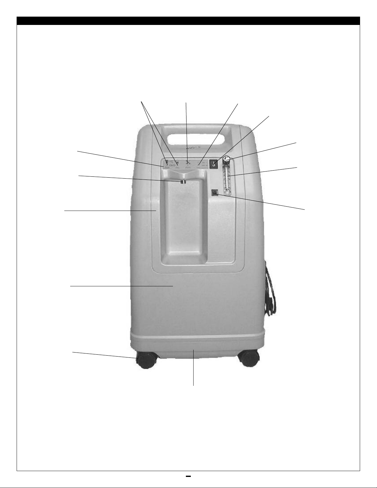
Figure 1 - Exterior Front View
FIGURES, DIAGRAMS, AND VIEWS
Light Panel
Oxygen
Outlet Port
Bib
OSD Indicator Lights
(OSD units only)
Service Required
Light (Red)
Power Light
(green)
Power Switch
Flow Meter Knob
Flow Meter
Circuit
Breaker
Front
Cover
Caster
Base
LT-1928
22
Page 23
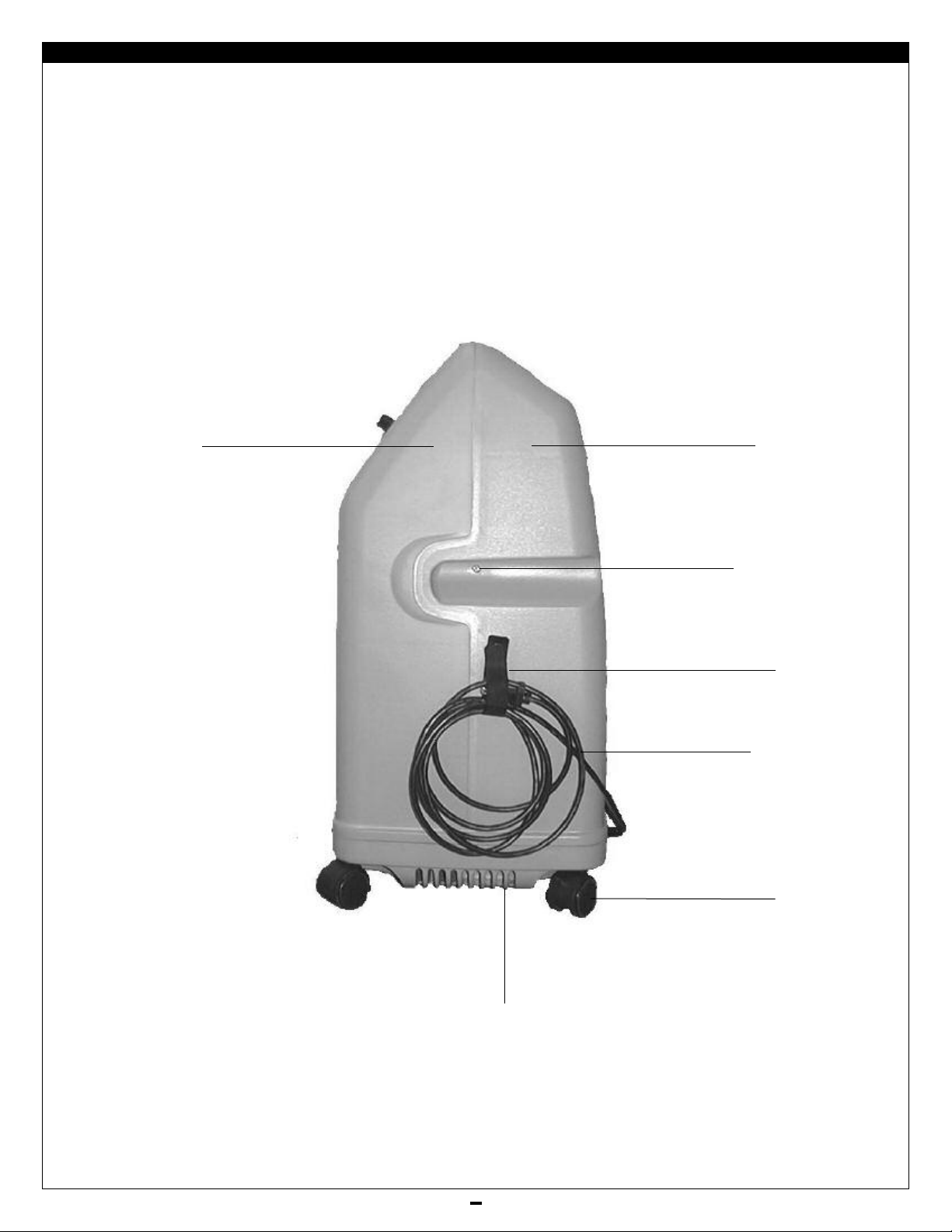
Figure 2 - Exterior Side View
FIGURES, DIAGRAMS, AND VIEWS
Front cover
Rear cover
Cabinet screw
Power
Cord Strap
Power Cord
Exhaust Grill
23
Caster
LT-1928
Page 24
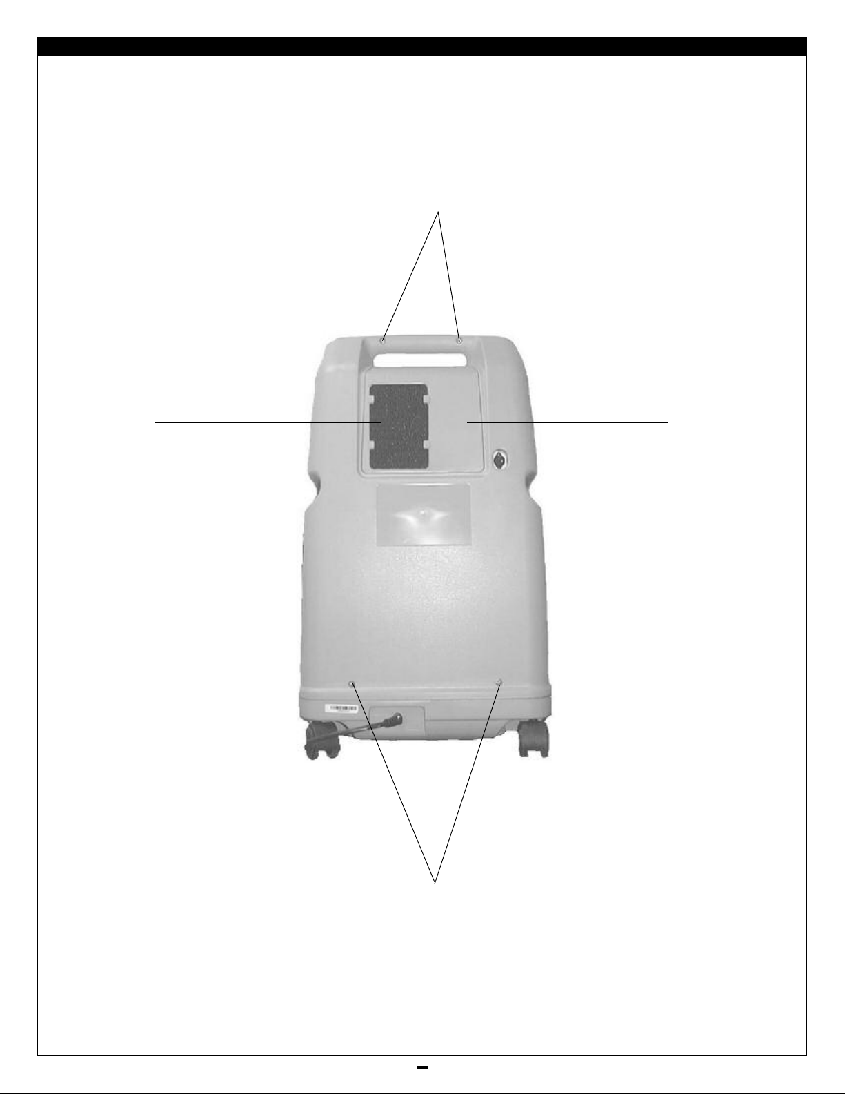
igure 3 - Exterior Rear View
F
FIGURES, DIAGRAMS, AND VIEWS
Cabinet Screws
Air
Filter
Filter Door
Communication Port
(with cover removed)
LT-1928
Cabinet Screws
24
Page 25
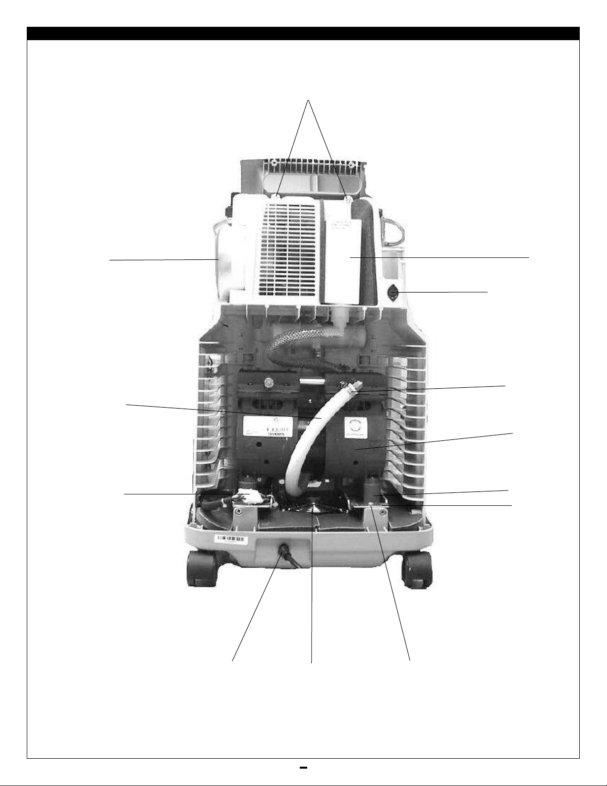
FIGURES, DIAGRAMS, AND VIEWS
Figure 4 - Interior Rear View (515ADS and 515ADZ)
Bib Screws
Accumulator Tank
Pressure Exhaust Hose
1/2" ID
(Silicone)
essor Connector
Compr
Intake
ia Filter
Bacter
Communication Port
Ladder Clamp
Compressor
Motor Mount
Compressor
Mounting Plate
Power Cord &
Strain Relief on
115 volt units
Cooling F
25
an
Mounting Plate Screw
LT-1928
Page 26
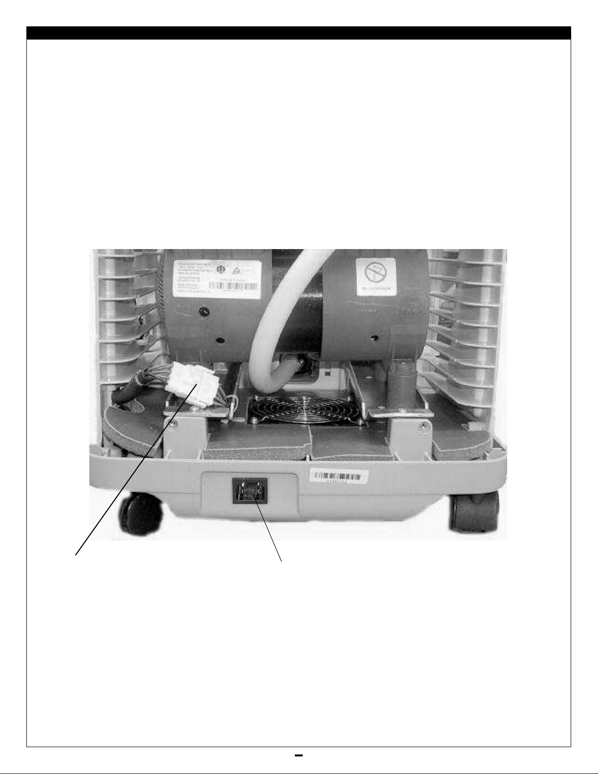
FIGURES, DIAGRAMS, AND VIEWS
Figure 4A - Interior, Rear Lower View (515AKS and 515AKZ)
LT-1928
Compressor
Connector
IEC Connector for
models 515AKS
and 515AKZ
26
Page 27
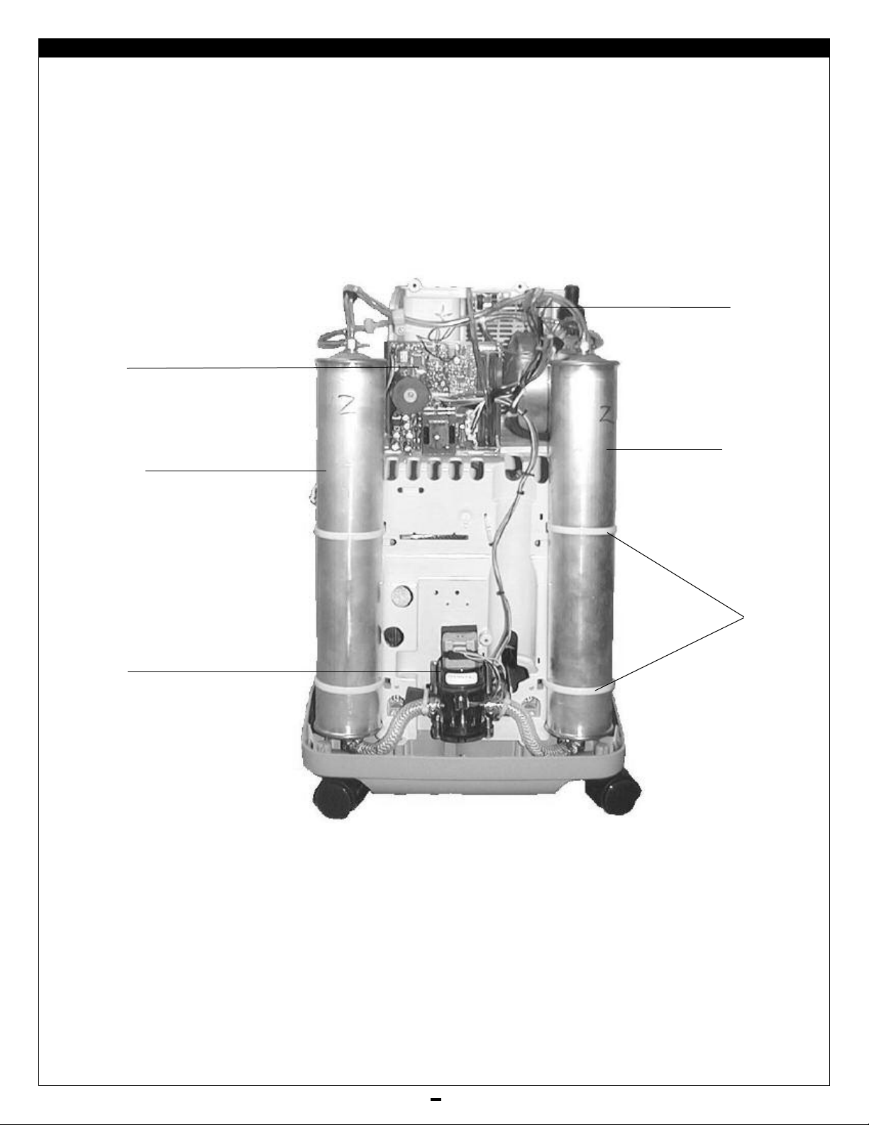
FIGURES, DIAGRAMS, AND VIEWS
igure 5 - Interior, Front View (515ADS and 515ADZ)
F
PC Board
Left Sieve Bed
Wire Harness
Right Sieve Bed
Rotary
Directional
Air Valve
Sieve Bed
Cable Ties
27
LT-1928
Page 28
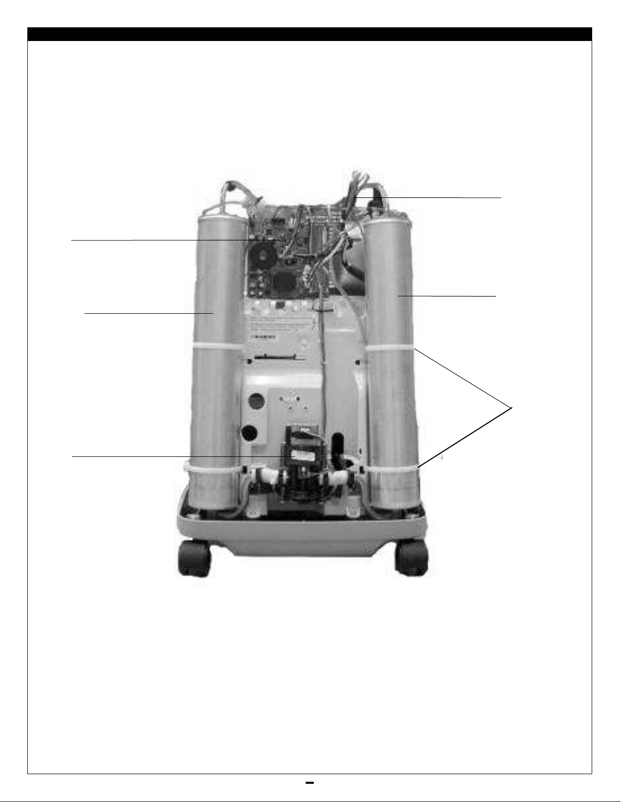
FIGURES, DIAGRAMS, AND VIEWS
Figure 5A - Interior, Front View (515AKS and 515AKZ)
NOTE: Sieve beds shown are used only on models 515AKS and 515AKZ.
PC Board
Left Sieve Bed
Wire Harness
Right Sieve Bed
Rotary
Directional
Air Valve
Sieve Bed
Cable Ties
LT-1928
28
Page 29
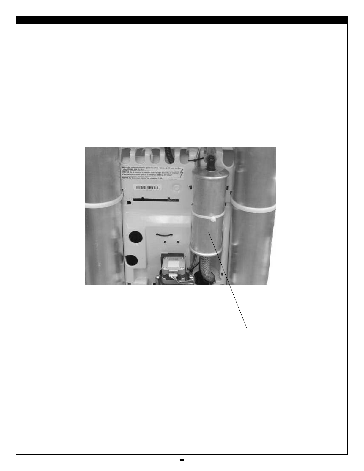
FIGURES, DIAGRAMS, AND VIEWS
Figure 5B - Interior, Front View, Close Up (515AKS and 515AKZ)
Intake Silencer for models
515AKS and 515AKZ
29
LT-1928
Page 30
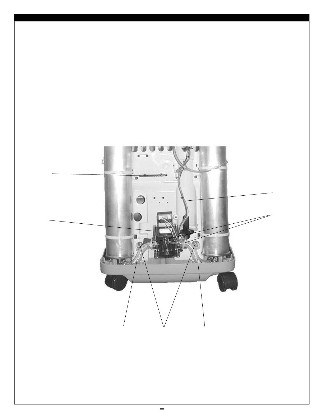
FIGURES, DIAGRAMS, AND VIEWS
Figure 6 - Interior, Front Lower View (515ADS and 515ADZ)
Bib Mounting
Slot
Rotary
Directional
Air Valve
Rotary Valve
Wire Harness
Rotary Valve
Mounting Cable
Ties
LT-1928
Left Sieve
Bed Hose
essor Mounting
Compr
Plate Hex Nut
30
Right Sie
Bed Hose
ve
Page 31

FIGURES, DIAGRAMS, AND VIEWS
Figure 6A - Interior, Front Lower View (515AKS and 515AKZ)
NOTE: Sieve beds shown are used only on models 515AKS and 515AKZ.
Bib Mounting
Slot
Rotary Valve
Wire Harness
Rotary
Directional
Air Valve
Left Sieve
Bed Hose
Compressor Mounting
Plate Hex Nut
Rotary Valve
Mounting
Hose Clamps
Right Sieve
Bed Hose
31
LT-1928
Page 32

FIGURES, DIAGRAMS, AND VIEWS
Figure 7 - Interior, Front Upper View (515ADS and 515ADZ)
Oxygen Outlet
Tubing 1/8" ID
PC Board
Valve Wire
Harness
Connector
Sieve Bed
Test Point
Hour Meter
Wires
Sieve Bed
Test Point
Oxygen Outlet
Tubing
1/8" ID
OSD
Capacitor for
Power Fail
Alarm
CAUTION: Do NOT
insert mounting
screw in this hole.
PC Boar
d Scr
ubing
T
w Meter
Flo
(shown disconnected
w
e
Fuse
for removal of Bib)
Oxygen
Accumulator
ank
T
LT-1928
32
Page 33

FIGURES, DIAGRAMS, AND VIEWS
Figure 7A - Interior, Front Upper View (515AKS and 515AKZ)
NOTE: Sieve beds shown are used only on models 515AKS and 515AKZ.
PC Board
Oxygen Outlet
Tubing 1/8" ID
Sieve Bed
Test Point
Hour Meter
Wires
Sieve Bed
Test Point
Oxygen Outlet
Tubing
1/8" ID
OSD
Valve Wire
Harness
Connector
PC Board Screw
Capacitor for
Power Fail
Alarm
Fuse
ubing to
T
Flow Meter
Oxygen
Accumulator
Tank
33
LT-1928
Page 34

FIGURES, DIAGRAMS, AND VIEWS
Figure 8 - Interior, Behind Bib View
Power Switch
Final Check Valve
Flow Meter
Final Bacteria Filter
Oxygen Outlet
Port Screws
Handle
Light Panel
Ribbon Connector
Circuit Breaker
*Red
*Red
Wire
Wir
e
Bib Tab
Switch Detail
Brown Wire (or Double Black Wires)
Double Black Wires (or Brown Wire)
LT-1928
*Either red wire can be connected to
either left hand terminal of the s
34
witc
h
Page 35

FIGURES, DIAGRAMS, AND VIEWS
Figure 9 - Interior,Top View (515ADS and 515ADZ)
Fixed Orifice
Sieve Bed
Check
Valve
Hour Meter
1/4" x 1/8"
Tubing Reducer
Check Valve
Pressure RegulatorSieve Bed
Accumulator Tank
Test Point Fitting
Sie
est P
T
ve Bed
oint
Communication Port
Wire Harness
ubing to Flo
T
35
w Meter
Sie
ve Bed
T
LT-1928
oint
est P
Page 36

FIGURES, DIAGRAMS, AND VIEWS
Figure 9A - Interior,Top View (515AKS and 515AKZ)
NOTE: Sieve beds shown are used only on models 515AKS and 515AKZ.
Sieve Bed Check
Valve
Communication Port
Wire Harness
Hour Meter
Sieve Bed
Check Valve
1/4" x 1/8"
Tubing Reducer
Pressure
Regulator
Accumulator Tank
Test Point Fitting
Accumulator Tank
T Fitting
Fixed Orifice
LT-1928
Sieve Bed
Test Point
Tubing to Flow Meter Sieve Bed Test Point
36
Page 37

FIGURES, DIAGRAMS, AND VIEWS
Figure 10 - Interior, Rear Lower View
Exhaust Muffler
Intake Filter
Elbow
Valve Exhaust Hose
1/2" ID Braided
Compressor
Connector
Capacitor
wer Cord
o
P
Connector
Cooling Fan Guard
(note correct orientation of fan guard)
Cooling Fan
Ladder Clamp
Pressure Exhaust
Hose (Silicone)
1/2" ID
37
LT-1928
Page 38

FIGURES, DIAGRAMS, AND VIEWS
Figure 11 - Compressor - Thomas Nexus
Pressure
Relief Valve
Intake Fitting
Exhaust Fitting
LT-1928
Electrical Connector
Motor Mount
Compressor
Mounting Plate
38
Page 39

FIGURES, DIAGRAMS, AND VIEWS
Figure 11A - Thomas Nexus Compressor With Head Removed
Retainer
Reed Valve
or Flapper
Head
Gasket
Valve Plate
(top view)
RodScrew Sleeve
Cup
Retainer Plate
Compr
essor Head
Pr
essur
e Relief Valve
Compressor
Exhaust Fitting
Valve Plate
(bottom view)
39
O-Ring
Reed Valve
or Flapper
Valve
Scr
Rod Screw
Cup Seal
w
e
LT-1928
Page 40

Figure 12 - Compressor - GSE
FIGURES, DIAGRAMS, AND VIEWS
Intak
e Fitting
Pressure
Relief Valve
Exhaust Fitting
Motor Mount
Compressor
Mounting Plate
LT-1928
Electrical Connector
40
Page 41

FIGURES, DIAGRAMS, AND VIEWS
Figure 12A - GSE Compressor With Head Removed
Compressor
Electrical Connector
Rod
Compressor
Head
Head Gasket
Valve Plate
(top view)
Retainer
Reed Valve
or Flapper
Screw
Sleeve
Cup
Seal
Cup
Seal
Cup
Retainer
Rod Scr
Cup
Retainer
essure
Pr
Relief
Valve
Connecting
Tubes
w
e
41
Valve Plate
(bottom vie
Valve
O-Ring
w)
Reed
or Flapper
Rod Screw
Screw
LT-1928
Page 42

Figure 13 - Rotary Valve
FIGURES, DIAGRAMS, AND VIEWS
Stepper Motor
Valve Wire
Harness
Left Sieve
Bed Fitting
Right Sieve
Bed Fitting
Front View
Pressure
Exhaust
Fitting
LT-1928
Rear View
42
Pressure
e
Intak
Fitting
Page 43

Figure 14 - Pneumatic Diagram
FIGURES, DIAGRAMS, AND VIEWS
43
LT-1928
Page 44

Figure 15 - Wiring Diagram
FIGURES, DIAGRAMS, AND VIEWS
(115 VOLT UNITS)
OLT UNITS)
V
(230
LT-1928
44
Page 45

WARRANTY INFORMATION
WARRANTY INFORMATION
DeVilbiss 515ADS/515ADZ Oxygen
Concentrators Limited Warranty
Sunrise Medical (“Sunrise”) warrants the DeVilbiss
515ADS/515ADZ Oxygen Concentrators, under the condi-
ions and limitations stated below.Sunrise warrants this equip-
t
ment to be free from defects in workmanship and materials
for five (5) years from date of factory shipment to the original
urchaser, (typically the healthcare provider).This warranty is
p
limited to the Buyer of new equipment purchased directly
from Sunrise, or one of its Providers, Distributors, or Agents.
unrise’s obligation under this warranty is limited to (1) prod-
S
uct repair (parts and labor) at its factory or at an Authorized
Service Center or (2) supplying a replacement for component
part(s).This warranty does not cover any labor charges
incurred in removing or replacing the warranted component
part(s) by any other service personnel. Routine maintenance
items, such as filters, are not covered under this warranty.
Warranty Claims Submissions
The original purchaser must submit any warranty claim to
Sunrise or to an Authorized Service Center. Upon verification
of the warranty status, instructions will be issued. For component part(s) return(s), the original purchaser shall be responsible to remove the defective component part(s). For all
returns, the original purchaser must (1) properly package the
unit or parts in a Sunrise approved shipping container, (2)
properly identify the claim with the Return Authorization
Number, and (3) send the shipment freight prepaid. Service
under this warranty must be performed by a qualified Sunrise
provider and/or an Authorized Service Center. Labor costs
incurred by a qualified Sunrise provider are excluded and will
not be reimbursed. Only labor costs incurred by an
Authorized Service Center are reimbursed.
NOTE:This warranty does not obligate Sunrise to provide a
loaner unit during the time that an oxygen concentrator is
undergoing repair.
NOTE: Replacement components are warranted for the
unexpired portion of the original Limited Warranty.
This warranty shall be voided, and Sunrise shall be relieved of
any obligation or liability if:
The equipment is operated or maintained outside the
•
parameters indicated in the Sunrise operating and service
instructions.
• Unqualified service personnel conduct routine maintenance,
servicing, or warranty repairs.
• Unauthorized parts or components (i.e., regenerated sieve
material) are used to repair or alter the equipment.
• Unapproved filters are used with the unit.
THERE IS NO OTHER EXPRESS WARRANTY. IMPLIED WARRANTIES, INCLUDING THOSE OF MERCHANTABILITY
AND FITNESS FOR A PARTICULAR PURPOSE, ARE LIMITED
TO THE DURATION OF THE EXPRESS LIMITED WARRANTY AND TO THE EXTENT PERMITTED BY LAW ANY AND
ALL IMPLIED WARRANTIES ARE EXCLUDED.THIS IS THE
EXCLUSIVE REMEDY AND LIABILITY FOR CONSEQUENTIAL AND INCIDENTAL DAMAGES UNDER ANY AND ALL
WARRANTIES ARE EXCLUDED TO THE EXTENT EXCLUSION IS PERMITTED BY LAW. SOME STATES DO NOT
ALLOW LIMITATIONS ON HOW LONG AN IMPLIED
WARRANTY LASTS, OR THE LIMITATION OR EXCLUSION
OF CONSEQUENTIAL OR INCIDENTAL DAMAGE, SO THE
ABOVE LIMITATION OR EXCLUSION MAY NOT APPLY TO
YOU.
This warranty gives you specific legal rights, and you may also
have other rights that vary from state to state.
NOTE: International model warranties may vary.
45
LT-1928
Page 46

ORDERING INFORMATION AND PARTS LIST
ORDERING INFORMATION
When ordering components, instruction guides, or service
manuals the following must be provided:
Unit Catalog Number
•
• Unit Serial Number
• Part Number
Quantity Required
•
DeVilbiss Concentrator Instruction Guide—part # A-515A
English/Spanish/French)
(
DeVilbiss Concentrator Instruction Guide—part # SE-515A
(English/Spanish/French/German/Italian/Dutch)
eVilbiss Concentrator Instruction Guide—part # P-515A
D
(English/Portuguese)
DeVilbiss 5 Liter Series Service Manual—part # LT-1917
(English)
DeVilbiss 5 Liter Series Service Manual—part # LT-1927
(English/Portuguese)
DeVilbiss 5 Liter Series Service Manual—part # LT-1928
(English/Spanish)
Orders may be placed by calling:
• Customer Service 800-333-4000
• Warranty parts - U.S.A. 800-333-4000
• Canada 905-660-2459
• International Department 814-443-4881
PARTS RETURN AND ORDERING POLICY
ALL DEFECTIVE COMPONENTS THAT ARE STILL UNDER
WARRANTY MUST BE RETURNED TO THE FACTORY IN
SOMERSET, PA WITHIN 30 DAYS AFTER SHIPMENT OF THE
NEW COMPONENTS. IF THE COMPONENTS ARE NOT
RECEIVED WITHIN THIS PERIOD, AN INVOICE WILL BE
ISSUED TO YOUR ACCOUNT.
REBUILT EXCHANGE PARTS PRICING IS AVAILABLE ONLY
ITH THE RETURN OF DEFECTIVE PARTS WITHIN 30
W
DAYS. COMPONENTS WILL THEN BE BILLED AT THE
REBUILT COST;THERE WILL BE A CHARGE FOR SHIPPING.
F THE DEFECTIVE COMPONENT IS NOT RECEIVED
I
WITHIN 30 DAYS,THEN A NEW COMPONENT INVOICE
WILL BE ISSUED TO YOUR ACCOUNT. COMPONENTS
HAT ARE OUT OF WARRANTY AND NOT ON A
T
REBUILT/EXCHANGE PROGRAM DO NOT HAVE TO BE
RETURNED TO THE FACTORY.
Before returning parts or units to the factory, call the Sunrise
Medical Customer Service Department (800-333-4000)
(814-443-4881) to obtain a return authorization number.
Include in the package a note indicating the return authorization number along with your company name, address, phone
number, and account number.The return authorization number
should also be written on the outside of the package.
To expedite your order for warranty or non-warranty parts, the
following information should be given to the representative:
• Catalog number
• Serial number
• Hour meter reading for each concentrator
• Account number
• Company name and address
• Description of problem
LT-1928
46
Page 47

ORDERING INFORMATION AND PARTS LIST
Accessories
Bubble Humidifier HUM16
Cannula CAN00
Cannula w/2.1m (7 ft) tubing CAN70
itting, Straight Hum. Adapter
F
44-506
4
Low Output Flow Meter 515LF-607
Oxygen Analyzer O2ANA
Oxygen Outlet Connector - Plastic CN100
Oxygen Tubing OST07, OST15,OST25, OST50
Components 515AKS 515ADS 515ADZ 515AKZ
Accumulator Tank 515ST-610 515ST-610 515ST-610 515ST-610
Cabinet Parts
Base 515KZ-604 515DZ-603 515DZ-603 515KZ-604
Bib 515ADS-603 515ADS-603 515ADZ-603 515ADZ-603
Communication Port Door 515ADZ-640 515ADZ-640 515ADZ-640 515ADZ-640
Compressor Box or Housing 515ADZ-604 515ADZ-604 515ADZ-604 515ADZ-604
Filter Door 515DZ-639 515DZ-639 515DZ-639 515DZ-639
Front Cover 515ADZ-601 515ADZ-601 515ADZ-601 515ADZ-601
Rear Cover 515ADZ-602 515ADZ-602 515ADZ-602 515ADZ-602
Cable Tie, (Sieve Bed) 505DZ-617 505DZ-617 505DZ-617 505DZ-617
Capacitor, Motor Start/Run
*2
MC44I-626
*2
515DZ-617
*2
515ADZ-616
*2
MC44I-626
Carton w/ Shipping Inserts 505DZ-606 505DZ-606 505DZ-606 505DZ-606
Caster, Non-locking 501DZ-603 501DZ-603 501DZ-603 501DZ-603
Check Valves
Bed Check Valve PVO2D-607 PVO2D-607 PVO2D-607 PVO2D-607
Final Check Valve PVO2D-607 PVO2D-607 PVO2D-607 PVO2D-607
Circuit Breaker 515KZ-615 515DZ-615 515DZ-615 515KZ-615
Cooling Fan 515UK-634 515DZ-634 515DZ-634 515UK-634
Cooling Fan Guard 515ADZ-633 515ADZ-633 515ADZ-633 515ADZ-633
Compressor
essor Rebuild Kit
Compr
*1
1
*
515AKZ-625
515ADZ-643
*1
*
1
515ADS-626
515DZ-643
*1
1
*
515ADZ-625
515ADZ-643
*1
*
1
515AKZ-625
515ADZ-643
Compressor Mounting Plate 501DZ-631 501DZ-631 501DZ-631 501DZ-631
Exhaust Muffler 515A-705 515A-705 515A-705 515A-705
Filters
Cabinet Air Filter 505DZ-604 505DZ-604 505DZ-604 505DZ-604
Extended Life Intake Filter 515DZ-605 515DZ-605 515DZ-605 515DZ-605
Final Bacteria Filter PV5LD-651 PV5LD-651 PV5LD-651 PV5LD-651
*2
*1
1
*
*1
CAUTION: The 515A series concentrators use either a
. Be sure to
Thomas compr
essor or a GSE compr
essor
order the correct part number when replacing/rebuilding the compressor. Capacitor is included with purchase
.
of compr
essor
*2
CAUTION: The 515ADS and 515ADZ series concentrators use either a
Thomas compr
essor with a 15 mfd
capacitor or a GSE compressor with a 22 mfd capacitor.
The 515AKS and 515AKZ series concentrators use a
.If replacement
GSE compr
essor with a 10 mfd ca
pacitor
is necessary, be sure the correct capacitor is installed
47
.
LT-1928
Page 48

ORDERING INFORMATION AND PARTS LIST
Components (continued) 515AKS 515ADS 515ADZ 515AKZ
Fittings
Accumulator Tank "Tee" 444-582 444-582 444-582 444-582
Flow Meters
tandard Flow Meter
S
05DZ-607
5
05DZ-607
5
05DZ-607
5
05DZ-607
5
Low Output Meter 515LF-607 515LF-607 515LF-607 515LF-607
Flow Meter Knob PVO2D-618 PVO2D-618 PVO2D-618 PVO2D-618
Foam Kit 515ADZ-600 515ADZ-600 515ADZ-600 515ADZ-600
Fuse (For PC Board) 515AKZ-610 515ADZ-627 515ADZ-627 515AKZ-610
Hoses
1/8" ID (Blue) (4' Lg) 444-554 444-554 444-554 444-554
1/4" ID (Blue) (4' Lg) 444-525 444-525 444-525 444-525
1/2" ID (Braided) (4' Lg) 444-549 444-549 444-549 444-549
1/2" ID (Braided) (Formed) 515ADZ-649 515ADZ-649 515ADZ-649 515ADZ-649
1/2" ID (Silicone) (2' Lg) 505DZ-634 505DZ-634 505DZ-634 505DZ-634
Hose Clamps
Plastic (1/4" ID Hose) 444-524 444-524 444-524 444-524
Plastic (1/2" ID Hoses) 444-538 444-538 444-538 444-538
Ladder Clamp (1/2" ID Hoses) 444-566 444-566 444-566 444-566
Hour Meter PV5LD-617 PV5LD-617 PV5LD-617 PV5LD-617
Light Panel 303DS-615 303DS-615 505DZ-615 505DZ-615
Motor Mounts 505IZ-609 505IZ-609 505IZ-609 505IZ-609
Nut (Compressor Mounting) 303DZ-630 303DZ-630 303DZ-630 303DZ-630
Oxygen Outlet Port 303DZ-606 303DZ-606 303DZ-606 303DZ-606
PC Board 515AKS-622 515ADS-622 515ADZ-622 515AKZ-622
Power Cord PV5LD-618 PV5LD-618 PV5LD-618 PV5LD-618
Power Cord Strap MC29D-657 MC29D-657 MC29D-657 MC29D-657
Power Cord Strain Relief 505DZ-645 505DZ-645 505DZ-645 505DZ-645
Power Switch 505DZ-508 505DZ-508 505DZ-508 505DZ-508
Pressure Regulator MC29D-612 MC29D-612 MC29D-612 MC29D-612
Screws
Cabinet 303DZ-628 303DZ-628 303DZ-628 303DZ-628
e Bed
v
Sie
515A-621 515DZ-619 515DZ-619 515A-621
Valve, Rotary 515ADZ-702 515ADZ-702 515ADZ-702 515ADZ-702
Valve Hose (Braided/Formed) 515ADZ-649 515ADZ-649 515ADZ-649 515ADZ-649
Wire Harnesses
Communication Harness 515DS-608 515DS-608 515DS-608 515DS-608
Main Harness 515AKS-623 515DZ-623 515DZ-623 515AKS-623
Valve Harness 515ADZ-621 515ADZ-621 515ADZ-621 515ADZ-621
ools
T
Pressure Test Assembly 303DZ-637
Pr
essur
O2D-601
PV
acuum Gauge
V
e
Service Kit 444-501
LT-1928
48
Page 49

SPECIFICATIONS
DEVILBISS 5-LITER SERIES
atalog Number 515ADS, 515ADZ 515AKS, 515AKZ
C
elivery Rate(Lower delivery rates 1 to 5 LPM
D
available for low flow applications)
aximum Recommended Flow
M
utlet Pressure
O
Electrical Rating 115V~, 60 Hz, 4.1 Amp 220V-230V~, 50 Hz, 1.7A; 230V~, 60 Hz, 2.4A
perating Voltage Range
O
7-127V~, 60 Hz 187-264V~, 50 Hz, 200V-264V~, 60 Hz
9
Oxygen Percentage 1-5 LPM=93%±3%
perating Altitude
O
tested at 21°C only)
(
A
0-1500 M (0-4921 ft) No degradation of performance
ested at nominal voltage only:
500-3000 M (4921-9842 ft) No degradation in performance expected
1
T
based on tests of similar products.
3000-4000 M (9842-13123 ft) Not recommended/Not tested
perating Environment Range*
O
10°C to 35°C, humidity range the operating voltage range
30% to 75% (tested at sea level).
of
Power Consumption 385 Watts Average 335 Watts Average
15ADS only-320 Watts @ 2.5 LPM & below 515AKS only-301 Watts @ 2.5 LPM & below
5
o degradation in performance across
N
Weight 50 lbs. (22.7 Kilograms)
Sound Level (ISO 8359:1996 from front) 48.0 dbA overall average
Dimensions 27.75"H x 16"W x 14"D (70.5 x 40.6 x 35.6 cm)
Pressure Relief Valve 40 psig±5psig (276 kPa±34.5 kPa)
Operating System Time Cycle / Pressure Swing
For units equipped with an OSD 84% ± 2%
the visible “low oxygen” indicator (The audible alarm will alert at approximately 75%.
will activate at the following level At less than 60%, the red “service required” light will activate.)
Storage Conditions -40°C to 70°C, humidity range of 10% to 100%, including condensation
Equipment Class and Type Class II Equipment Double Insulated; Type B Applied Part
Approval Body CSA TUV
and CAN/CSA-C22.2 No. 601.1-M90 EN60601-1:1990+A1+A2+A13
Safety Standard EN ISO8359:1996
EMC Compliance To: IEC 60601-1-2
Typical Accumulator Pressure at
Maximum Recommended Flow
@ Sea Level 22-27 psig (150-190 kPa)
@ 750 M (2460 Ft) 20-25 psig (138-172 kPa)
@ 1500 M (4921 Ft) 17-21 psig (120-145 kPa)
ote: The OSD performance at 10°C to 35°C, 95% R.H. through voltage range on the 515ADS verified at 670m.
*N
Specifi
*2
*
3
s subject to change without notice.
on
cati
Note: EN ISO8359:1996 does not apply to 515AKZ.
Note: Wattage listed is for 50 Hz operation, wattage at 60 Hz will be higher.
LPM
5
.5 psig (58.6 kPa)
8
cross the voltage range:
2
*
3
*
49
LT-1928
Page 50

TABLA DE CONTENIDOS
INFORMACIÓN GENERAL
Introducción .........................................................................................................................................................................................................................51
Medidas de Seguridad Importantes ................................................................................................................................................................................52
Precauciones de Seguridad y Advertencias Generales ..............................................................................................................................................52
ESEMBALAJE Y AJUSTE
D
Inspección Inicial .................................................................................................................................................................................................................53
Ajuste del Paciente .............................................................................................................................................................................................................53
nstrucciones de Funcionamiento ...................................................................................................................................................................................54
I
MANTENIMIENTO
Sistema de Alerta del Paciente ........................................................................................................................................................................................55
Manutenção de Rotina del Paciente ...............................................................................................................................................................................55
Mantenimiento Preventivo Periódico del Proveedor de Asistencia Domiciliaria ................................................................................................56
Manutenção Entre Pacientes ............................................................................................................................................................................................56
Resumen de Mantenimiento Preventivo .......................................................................................................................................................................56
SOLUCIÓN DE PROBLEMAS
Funcionamiento del Sistema .............................................................................................................................................................................................57
Secuencia de Funcionamiento Normal ..........................................................................................................................................................................57
Solución de Problemas Simplificado ...............................................................................................................................................................................58
Solución de Problemas – Cuadro A ...............................................................................................................................................................................59
Solución de Problemas – Cuadro B ...............................................................................................................................................................................60
Solución de Problemas – Cuadro C ...............................................................................................................................................................................60
Solución de Problemas – Cuadro D ..............................................................................................................................................................................60
Solución de Problemas – Cuadro E ...............................................................................................................................................................................60
Solución de Problemas – Cuadro F ................................................................................................................................................................................61
PRUEBA DE COMPONENTES, REPARACIÓN Y REEMPLAZO
Procedimientos de Reparación Apropiados .................................................................................................................................................................62
Remoción del Gabinete ...................................................................................................................................................................................................62
Prueba de Acumulador de Presión ..................................................................................................................................................................................63
Condensador .......................................................................................................................................................................................................................63
Compresor ...........................................................................................................................................................................................................................63
Ventilador de Enfriamiento ...............................................................................................................................................................................................65
Válvula de Control Final ....................................................................................................................................................................................................65
Medidor de Flujo ................................................................................................................................................................................................................66
Medidor de
Tiempo
............................................................................................................................................................................................................66
Tamices Moleculares ..........................................................................................................................................................................................................66
dón Eléctrico ................................................................................................................................................................................................................
Cor
67
Interruptor de Corriente ..................................................................................................................................................................................................67
Regulador de Presión
Placa de Cir
cuitos Impresos (Placa PC)
.........................................................................................................................................................................................................67
.......................................................................................................................................................................
68
Válvula Rotativa ...................................................................................................................................................................................................................68
Válvulas de Control de
FIGURAS,
DIAGRAMAS Y VISTAS
Tamices ......................................................................................................................................................................................69
Índice de Figuras, Diagramas Y Vistas .............................................................................................................................................................................70
Vistas Exteriores ...........................................................................................................................................................................................................71-73
Vistas Interior
es ............................................................................................................................................................................................................74-86
Otras Figuras .................................................................................................................................................................................................................87-91
Diagramas Neumáticos y de Cableado ...................................................................................................................................................................92-93
INFORMA
CIÓN DE GARANTIA
................................................................................................................................................................................
94
INFORMACIÓN DE ÓRDENES Y LISTADO DE PARTES
Información de Órdenes ...................................................................................................................................................................................................95
olución de Partes y Política de Órdenes ...............................................................................................................................................................95
v
De
Listado de Partes ..........................................................................................................................................................................................................96-97
ESPECIFICACIONES .........................................................................................................................................................................................................98
T
L
-1928
50
Page 51

INFORMACIÓN GENERAL
INTRODUCCIÓN
Este Manual de Servicio está diseñado para proveer a los
técnicos de servicio calificados y proveedores de Asistencia
Domiciliaria pertenecientes a la División de Productos
Médicos Respiratorios de Sunrise Medical, con procedimientos apropiados de mantenimiento, servicio, seguridad y
reparación para el Concentrador de Oxígeno DeVilbiss.
eer y entender toda la información contenida en este man-
L
ual de servicios antes de poner en funcionamiento o realizar
cualquier maniobra de mantenimiento en el concentrador.
Cualquier concentrador de oxígeno es un equipo que
provee oxígeno altamente concentrado para aplicaciones
terapéuticas.
El aire ambiental es una combinación de 78% de Nitrógeno,
21% de Oxígeno, 1% de Argón y otros gases. El concentrador absorbe el aire ambiental, separa el nitrógeno del
oxígeno y provee oxígeno concentrado al paciente a través
del puerto de oxígeno.
Para un mayor y más profundo curso de capacitación,
Sunrise Medical provee cursos de servicio de concentradores de oxígeno. Para obtener información sobre los
cursos de servicio, contacte nuestro Departamento de
Servicios Técnicos Respiratorios al
443-4881)
.
1-800-333-4000 (814-
NOTA: Sunrise Medical se reserva el derecho de alterar o cam-
biar el diseño de las series de Concentradores de Oxígeno
DeVilbiss. Por lo tanto,pueden existir diferencias menores en la
construcción o en los componentes entre la unidad que usted
posee y la descrita en este manual.
51
LT-1928
Page 52

INFORMACIÓN GENERAL
MEDIDAS DE SEGURIDAD IMPORTANTES
Leer todas las instrucciones antes de hacer funcionar el concentrador de oxígeno. La información importante se encuentra
esaltada por estos términos:
r
ADVERTENCIA: Información de seguridad sobre peli-
ros que pudieran causar lesiones serias o muerte.
g
PRECAUCIÓN: Información para prevenir daños al
producto.
NOTA:
Información a la que usted debería prestar especial
atención.
PRECAUCIONES DE SEGURIDAD Y ADVERTENCIAS
GENERALES
A. La Ley Federal (EE.UU.) restringe la venta de este equipo por
o por orden de un médico.
B.
ADVERTENCIA: El oxígeno promueve
incineración rápida. No fumar mientras utiliza
esta unidad o estando cerca de una persona que recibe
terapia de oxígeno. No operar el concentrador de
oxígeno dentro de un radio mínimo de cinco pies (1,6
m) de objetos calientes, chispeantes o quemándose o
de llamas. No utilizar en habitaciones con calefacción
a base de parafina o calentadores portátiles de gas.
C. No colocar el humidificador con un paciente que requiere
oxígeno a menos que esté prescrito por un profesional médico y luego, sólo deberá utilizarse un humidificador de tipo burbuja.
D. No conectar el concentrador de oxígeno a un tomacorriente
controlado por un interruptor de pared; el tomacorriente
debería estar independiente de otros artefactos.
E. No utilizar un adaptador eléctrico o cable de extensión con el
concentrador de oxígeno.
Sólo debe hacer funcionar el concentrador de oxígeno con
.
F
todos los filtros en su lugar; no hacer funcionar si el filtro de
aire está mojado
.
ADVERTENCIA: Peligro de choque eléctrico. No reti-
G.
rar el gabinete. El gabinete deberá ser removido por
un proveedor calificado de Asistencia Domiciliaria de
Sunrise Medical.
DVERTENCIA: Desconectar el cordón eléctrico del
H.A
tomacorriente antes de realizar reparaciones en la
unidad. Se deberán tomar medidas de precaución adicionales si fuese necesario hacer funcionar la unidad
una vez removido el gabinete.
I. ADVERTENCIA: No utilizar aceites, grasas o solventes
/ limpiadores a base de petróleo sobre o cerca de la
unidad. Utilizar sólo materiales que son compatibles
con el oxígeno.
J. ADVERTENCIA: Peligro de Choque Eléctrico.Al
reemplazar el condensador, no tocar las terminales o
permitir que objetos metálicos estén en contacto con
las terminales del condensador. El condensador puede
contener carga durante varios días luego de que la
unidad ha sido apagada. El condensador está ubicado
en la base de la unidad a un costado del ventilador de
enfriamiento.
K. Utilizar sólo repuestos y accesorios para concentradores de
Sunrise Medical.
L. No utilizar material para tamices regenerado.
T
L
-1928
52
Page 53

DESEMBALAJE Y AJUSTE
INSPECCIÓN INICIAL
Se sugiere realizar una inspección general al momento de
recibir el concentrador de oxígeno.
1. Luego de sacar el Concentrador de Oxígeno DeVilbiss de la
caja de cartón, examinarlo por daños exteriores. Si hubiera
ocurrido daño durante su traslado, contactar al Departamento
de Atención al Cliente de Sunrise Medical al 1-800-333-4000
(814-443-4881) para obtener instrucciones específicas.
Guardar la caja de cartón en caso de posible devolución; notar
la posición de la unidad y del material de embalaje.
2. Abrir la puerta del filtro (Figura 3) y anotar la cantidad de
oras en el contador de horas.Verificar que el filtro de aire se
h
encuentra en su lugar.
3. Verificar para asegurar que el filtro de ingreso de bacterias
(Figura 4) está en su lugar.
4. Enchufar la unidad al tomacorriente, encender la unidad “ON”
y verificar las alarmas visibles y audibles.
5. Ajustar el medidor de flujo al máximo flujo por litro recomendado y dejar la unidad funcionando por lo menos durante 20
minutos.
6. Utilizar un analizador de oxígeno para verificar la concentración.
NOTA: Si la unidad no funciona apropiadamente (concentrador de oxígeno fuera de las especificaciones) o si se detecta
algún daño interno, contactar al Departamento de Atención al
Cliente de Sunrise Medical al 1-800-333-4000 (814-443-4881).
AJUSTE DEL PACIENTE
1. Colocar la unidad cerca de un tomacorriente en la habitación
donde el paciente pasa la mayor parte de su tiempo.
NOTA: No conectar a un tomacorriente controlado por un
interruptor de pared. La toma debería ser independiente de otros
artefactos.
2. Colocar la unidad a por lo menos 6 pulgadas (16 cm) de las
paredes, cortinas u otros objetos que pudieran prevenir el
flujo de aire apropiado fuera del concentrador de oxígeno.
Ubicar la unidad a un mínimo de 5 pies (1,6 m) de chimeneas,
3.
radiadores, estufas y rejillas de aire caliente.
ADVERTENCIA: El oxígeno promueve incineración rápida. No fumar mientras utiliza esta
unidad o estando cer
ca de una persona que r
ecibe terapia de oxígeno. No operar el concentrador de
oxígeno dentro de un radio mínimo de cinco pies (1,6
m) de objetos calientes, chispeantes o quemándose o
de llamas. No utilizar en habitaciones con calefacción
a base de parafina o calentadores portátiles de gas.
ADVERTENCIA: Peligro de choque eléctrico. Sólo los
veedores calificados de Asistencia Domiciliaria de
o
pr
Sunrise Medical pueden r
etirar el gabinete
.
4. Conectar los accesorios de oxígeno apropiados (tubos de
oxígeno o humidificador) al puerto de salida de oxígeno.
NOTA: Se permiten un máximo de 50 pies (15 metros) de
tubo más 7 pies (2,1 metros) de cánula más un humidificador
e burbuja entre el concentrador y el paciente.
d
Única Conexión Detubos de Oxígeno (Figura 1)
1. Insertar la cánula (parte #CN100) en el puerto de salida de
oxígeno.
2. Colocar el tubo de oxígeno de 5/32 pulg. (4 mm) D.I. (parte
#OST07, OST15, OST25, ó OST50)
Conexión de tubo de Oxígeno con Humidificación
Si el profesional médico ha prescrito un humidificador de
oxígeno como parte de la terapia del paciente, seguir estos
pasos:
1. Llenar la botella del humidificador (parte #HUM16) con agua
destilada. No sobrecargar. (Si se utiliza una botella precargada,
ver el Paso 3).
2. Colocar la tuerca de mariposa ubicada en la parte superior de
la botella del humidificador al puerto de salida de oxígeno para
que quede suspendida. Comprobar que está bien ajustada.
3. Colocar el tubo de oxígeno de 5/32 pulg. (4 mm) D.I. (parte #
OST07, OST15, OST25 ó OST50), no exceder los 50 pies (15
metros) directamente a la boca de la botella del humidificador.
NOTA: Para un funcionamiento óptimo, el Concentrador de
Oxígeno DeVilbiss posee una presión de salida nominal
preestablecida de 8,5 psi (58,6 kPa). Utilizar solamente humidificadores de tipo burbuja. No utilizar humidificadores de tipo
jet.
NOTA: La condensación desde el humidificador puede ocurrir en tubos más largos o si el tubo yace sobre un piso frío.
Esto puede ser reducido utilizando un pie de humidificador
removible (parte #MC44DM-509).
Para utilizar el pie:
1. Conectar el adaptador recto de humidificador (parte #444-
506) a la botella haciendo girar la tuerca de mariposa en la
unidad del humidificador hasta que esté ajustada.
2. Asegurar la botella en la correa.
3. Conectar un extremo del tubo de oxígeno en la salida de
oxígeno de la unidad y el otro extremo al adaptador plástico
en el humidificador. Colocar el humidificador cerca del
paciente.
Cuando está listo para funcionar
Conectar la cánula nasal (parte #CAN00), el catéter o la mas-
1.
carilla al tubo de oxígeno (según las instrucciones del fabricante).
2. Seguir las instrucciones de funcionamiento que se detallan a
continuación.
53
LT-1928
Page 54

DESEMBALAJE Y AJUSTE
INSTRUCCIONES DE FUNCIONAMIENTO
1. Retirar completamente el cordón eléctrico de la correa.
Asegurar que el interruptor de encendido está en la posición
OFF”.
“
2. Unidades de 115 Voltios – Insertar el enchufe en un
tomacorriente. El Concentrador de Oxígeno DeVilbiss utiliza
un enchufe polarizado de dos puntas y está doblemente aislado para protección contra choques eléctricos.
DVERTENCIA: El enchufe de los concentradores
A
DeVilbiss 515ADZ y 515ADS posee una punta más
ancha que la otra. Para reducir el riesgo de choque
eléctrico, este enchufe sólo se adaptará al
tomacorriente en una sola posición. No intentar alterar esta característica de seguridad.
ADVERTENCIA: El uso inapropiado del cable eléctrico
y los enchufes puede causar quemaduras, fuego u otros
peligros de choque eléctrico. No utilizar la unidad si el
cable eléctrico está dañado.
ADVERTENCIA: El oxígeno promueve incineración
rápida. No fume mientras utiliza esta unidad o
estando cerca de una persona que recibe terapia de
oxígeno.No opere el concentrador de oxígeno dentro de
un radio mínimo de cinco pies (1,6 m) de objetos
calientes, chispeantes o quemándose, o de llamas. No utilizar en habitaciones con calefacción a base de parafina o
calentadores portátiles de gas.
3. Presionar el interruptor de encendido a la posición “ON”.
Cuando la unidad está encendida, la luz de “Service Required”
(se Requier
momentáneamente (el sistema de alerta del paciente).
ower” (Encendido) también se encenderá.
“P
e Servicio) se encenderá y una señal audible sonará
La luz
Sólo el Concentrador de Oxígeno DeVilbiss con
®
OSD
El OSD es un dispositivo opcional dentro de los concentradores DeVilbiss que monitor
El OSD funciona así:
unidad.
• Oxígeno Normal (luz verde) – pureza de oxígeno normal
• Oxígeno Bajo (luz amarilla) – pureza de oxígeno baja –
equiere servicio
r
ea el oxígeno producido por la
NOTA: Si la pureza del oxígeno continúa decreciendo se
escuchará una señal audible intermitente. Si la pureza del
oxígeno aún continúa decreciendo a un nivel lo suficientemente bajo, la luz amarilla de “Low Oxygen” (Oxígeno Bajo) se
apagará y la luz roja de “Requiere Servicio” se encenderá.
NOTA: Ver Especificaciones para ajustes de alarmas específicos.
uando la unidad con OSD se encuentra encendida (“ON”),
C
las cuatro luces indicadoras (Encendido, Requiere Servicio,
Oxígeno Bajo y Oxígeno Normal) en el panel frontal se
encenderán por un momento. Luego de algunos segundos, sólo
las luces “Encendido” y “Oxígeno Normal” permanecerán
encendidas.
NOTA: Luego de encender la unidad (ON), el OSD lleva a
cabo un diagnóstico evaluativo continuo para verificar fallas
electrónicas. Si el OSD detecta esta condición durante el funcionamiento del concentrador, la luz verde del OSD “Oxígeno
Normal” se apagará, se activará una señal audible y parpadeará
la luz roja de “Requiere Servicio”.
De no ocurrir esto y
durante los primeros quince minutos de funcionamiento, la luz verde de “Oxígeno Normal” permanecerá
encendida durante el proceso de estabilización de
oxígeno.Luego de este tiempo, el OSD comenzará a
monitorear la pureza del oxígeno cada segundo.
4. Mover lentamente la perilla de medidor de flujo hasta que la
bola del medidor esté centrada en la línea junto a la velocidad
de flujo apropiada.
NOTA: Cuando la perilla del medidor de flujo es girada en la
dirección de las agujas del reloj, el flujo decrece (y eventualmente cerrará el flujo de oxígeno). Cuando la perilla es girada
en el sentido contrario, el flujo aumenta.
NOTA: Usar un medidor de flujo bajo (parte # 515LF-607)
para las velocidades de flujo menores de 1 lpm.
NOTA: La unidad puede requerir hasta 20 minutos para que
la concentración de oxígeno y la velocidad de flujo se estabilicen. La velocidad de flujo deberá ser monitoreada y reajustada
si fuese necesario.
5. El medidor de flujo tiene un dispositivo de bloqueo. Si fuese
necesario preajustar y bloquear una velocidad de flujo prescrita, apretar el tornillo de ajuste ubicado en la tuerca hexagonal
justo debajo de la perilla de control utilizando una llave Allen
de 1/16 pulg. No se podrá realizar un ajuste sin aflojar el
tornillo de ajuste previamente.
6. El concentrador de oxígeno DeVilbiss está ahora listo para ser
utilizado.
T
L
-1928
54
Page 55

MANTENIMIENTO
SISTEMA DE ALERTA DEL PACIENTE
El Sistema de Alerta del Paciente del Concentrador de Oxígeno
DeVilbiss detecta fallas en los componentes de la unidad. Este
istema está compuesto por alarmas visibles y audibles que aler-
s
tan al paciente en el caso de mal funcionamiento de la unidad.
La alarma visible está localizada en el frente del panel (Figura 1) y
lee “Servicio Requerido”. El sistema de alarma audible está energizado internamente; no requiere baterías. Cuando las luces indicadoras se encienden o la alarma audible suena en otro momento que no sea durante el encendido de la unidad, es indicador de
que ha ocurrido algún problema.
odelos sin OSD:
M
• Falla de energía (Luz roja intermitente “Servicio Requerido
y alarma audible pulsante)
• Flujo Bajo (Luz roja continua “Servicio Requerido y alarma
audible)
Modelos con OSD:
• Falla de energía (Luz roja intermitente “Servicio
Requerido” y alarma audible pulsante)
• Flujo Bajo (por debajo de los 0,5 lpm) (Luz roja continua
“Servicio Requerido y alarma audible)
• Oxígeno por debajo de lo normal (84% a 75%, luz amarilla
“Oxígeno Bajo”; 75% a 60%, luz amarilla “Oxígeno Bajo” y
alarma audible intermitente; menos de 60%, luz roja
“Servicio Requerido” y alarma audible intermitente).Ver
Especificaciones para ajustes de alarma específicos.
Las alarmas visible y audible se activarán aproximadamente 15
minutos en una situación de falta de energía. Si la unidad es
encendida “ON” sin electricidad o la misma se interrumpiera
posteriormente, la alarma no sonará durante los primeros 10
segundos. Luego de este tiempo, la alarma producirá un pulso
audible con intervalos de algunos segundos mientras que la
alarma visible parpadea. La energía para esta alarma es provista
por un condensador en la Placa PC
NOTA: Si el concentrador no ha sido utilizado durante un
período pr
durante algunos minutos antes de que la alarma de falla de
energía se active
La placa PC (circuito impreso) (Figura 5) es responsable de
controlar el sistema y las alarmas.
NO
liberación audible de presión (como un chasquido) desde una
válvula de liberación de presión ubicada en el cabezal del com-
esor.
pr
olongado,
A:
T
Una condición de alta pr
la unidad deberá mantenerse funcionando
.
.
esión está indicada por una
por el fabricante. Si no se proveyeron instrucciones de
limpieza, deberán seguirse estos pasos:
• Lavar la botella del humidificador en una solución de agua
caliente y detergente lavavajillas.
• Sumergir el humidificador en una solución de una parte de
vinagre blanco y tres partes de agua caliente por 30-45
minutos. La solución actúa como agente germicida.
• Enjuagar profundamente bajo el agua caliente del grifo y
rellenar con agua destilada. No sobrecargar.
Cánula / Mascarilla y Tubos
El paciente deberá limpiar y reponer la cánula o mascarilla y
los tubos según instrucciones del fabricante.
Filtro de Aire y Conector de Salida de Oxígeno
El filtro de aire (Figura 3) y el conector de salida de oxígeno
deberán ser limpiados por el paciente por lo menos una vez a
la semana. Para limpiarlos deberá seguir los pasos siguientes:
1. Retirar el filtro de aire ubicado en la parte posterior de la
unidad. Retirar el conector de salida de oxígeno (si es utilizado)
del puerto de salida de oxígeno (Figura 1).
2. Lavar en una solución de agua tibia y detergente lavavajillas.
3. Enjuagar profundamente bajo el agua tibia del grifo y secar con
toalla. El filtro deberá estar completamente seco antes de ser
reinstalado.
ADVERTENCIA: No operar la unidad sin el filtro de
aire o mientras el mismo se encuentra todavía húmedo.
NOTA:
vamente en ambientes con grandes cantidades de polvo y
pelusa.
PRECAUCIÓN: El funcionamiento del Concentrador
de Oxígeno DeVilbiss en ambientes extremos o sin el
filtro de aire causarán la oclusión prematura del filtro
de ingreso de bacterias y un decaimiento en el
r
El filtro de aire deberá ser monitoreado más exhausti-
endimiento de la unidad.
Gabinete Exterior
El paciente deberá limpiar el gabinete exterior del concentrador utilizando un paño o esponja húmedos con un
limpiador doméstico suave. Secar con un paño.
MANTENIMIENTO DE RUTINA DEL PACIENTE
El paciente que utiliza oxígeno deberá realizar el siguiente
mantenimiento:
Humidificador de Oxíg
eno (sólo botellas
reutilizables)
El paciente deberá limpiar la botella del humidificador diaria
vistas
El paciente deberá seguir las instrucciones pr
.
mente
o
ADVERTENCIA: No aplicar líquidos directamente
sobre el gabinete o utilizar cualquier solvente o
agentes de limpieza a base de petróleo.
-
55
LT-1928
Page 56

MANTENIMIENTO
MANTENIMIENTO PREVENTIVO PERIÓDICO DEL
PROVEEDOR DE ASISTENCIA DOMICILIARIA
Todos los Concentradores de Oxígeno DeVilbiss son proba-
os en la fábrica. Para asegurar un funcionamiento continuo
d
libre de problemas, el siguiente mantenimiento preventivo
deberá ser realizado por el proveedor de asistencia
omiciliaria durante las visitas periódicas a los pacientes que
d
usan oxígeno. La falta de mantenimiento preventivo de la
unidad anulará los términos de la garantía.
1. Verificar la concentración de oxígeno con un analizador de
oxígeno (parte #O2ANA) cada 3 meses en unidades sin OSD,
o cada dos años en unidades con OSD.
a. Calibrar el analizador de oxígeno previo a la verificación de
la concentración de oxígeno. El analizador deberá ser calibrado apropiadamente utilizando los procedimientos
recomendados por el fabricante.
NOTA: Los cambios en temperatura, altitud o humedad
pueden afectar la lectura del analizador de concentración de
oxígeno. El analizador deberá ser calibrado en condiciones
similares a las de la ubicación del concentrador.
b. El concentrador deberá estar encendido por un mínimo de
20 minutos antes de verificar la concentración de oxígeno.
c. Conectar el analizador al puerto de salida de oxígeno de la
unidad (Figura 1) y esperar hasta que la pantalla se estabilice.
d. Tomar nota de la lectura.
2. Verificar las luces indicadoras y la alarma audible cada dos
años. Cuando el interruptor de encendido está en “ON”,
escuchar la alarma audible y verificar si las luces del panel indicador frontal están funcionando.
3. Cambiar el filtro de ingreso como se indica a continuación:
a. Filtro de ingreso de bacterias de vida prolongada (parte #
515DZ-605) – Inspeccionar una vez al año. Cambiar si fuera
necesario, sin exceder las 8.760 horas.
b. Abrir la puerta del filtro y reemplazar el mismo según sea
necesario.
4. Cambiar el filtro final de bacterias (parte # PV5LD-651) cada
dos años ó 17.520 horas.
etirar el gabinete y aflojar el
Desenchufar la unidad,
a.
r
babero.
Retirar la manguera a cada lado del filtro (Figura 8) y
.
b
.
descar
tar el filtr
o
c. Instalar el nuevo filtro final de bacterias con la indicación
“IN” hacia el medidor de flujo.
Ajustar el baber
d.
einstalar el gabinete
o y r
.
5. Verificar el rendimiento del sistema después de funcionar
durante dos años midiendo la oscilación de presión del acumu-
. Utilizar la Prueba de
lador
capítulo
Prueba de Componentes, Reparación y Reemplazo.
esión del Acumulador
Pr
descrita en el
NOTA: Este Programa de Mantenimiento Preventivo
refleja:
• 5.000 horas de uso equivalentes a un año
• un ambiente de funcionamiento limpio y normal
El proveedor de asistencia domiciliaria es responsable de:
• determinar la condición del ambiente de funcionamiento
del concentrador
• determinar una frecuencia de mantenimiento preventivo
(que no exceda el programa establecido más arriba, el
cual toma en consideración el ambiente de funcionamiento específico)
MANTENIMIENTO ENTRE PACIENTES
1. Descartar los tubos de oxígeno, la cánula y la botella del
humidificador.
2. Lavar o reemplazar el filtro de aire del gabinete.
3. Lavar el gabinete del concentrador.
4. Verificar la concentración de oxígeno. Si la unidad se encuentra
dentro de la especificación, el filtro de ingreso de bacterias de
vida prolongada no necesitará ser reemplazado entre
pacientes.
RESUMEN DE MANTENIMIENTO PREVENTIVO
Paciente
Diariamente Limpiar la botella del humidificador (si se uti-
liza).
Semanalmente Limpiar el filtro de aire en la parte posterior
de la unidad.
Limpiar el exterior del gabinete.
Otros Limpiar y reemplazar la cánula / mascarilla y
tubos según instrucciones del fabricante.
Proveedor de asistencia domiciliaria
Cambiar el filtro de ingreso de bacterias cuando sea
necesario siguiendo los requerimientos en el paso 3.
erificar la concentración de o
3 meses
V
sin OSD.
Verificar el ambiente del concentrador y establecer
intervalos de mantenimiento de menos de 3 meses
si se requiere.
2 años Verificar las alarmas audibles y las luces indicadoras
Cambiar el filtr
o final de bacterias (cambio dentro
de las 17.520 horas).
Verificar el rendimiento del sistema.
erificar la concentración de oxígeno en unidades
V
con OSD.
xígeno en unidades
T
L
-1928
56
Page 57

SOLUCIÓN DE PROBLEMAS
FUNCIONAMIENTO DEL SISTEMA
El Concentrador de Oxígeno DeVilbiss utiliza un sistema de
absorción oscilante de presión. El aire es llevado dentro de la
nidad a través de los filtros de aire y dentro de un compre-
u
sor de doble cabezal.
En la Figura 14 se muestra un diagrama neumático del sistema.
El aire comprimido pasa a través de una válvula rotativa (Figura
), el cual circula a un rango determinado y es dirigido hacia
5
uno de los dos tamices. Los tamices contienen material de
colado molecular que es un silicato inorgánico producido sin-
éticamente. Es muy poroso y tiene la capacidad única de
t
absorber nitrógeno selectivamente del aire cuando pasa a
través de los tamices.
Mientras uno de los tamices está siendo presurizado, el otro
es rápidamente despresurizado. Esto permite al nitrógeno,
absorbido durante la presurización, circular hasta ser liberado
del material de colado.
El nitrógeno es liberado a través de los puertos de escape ubicados en el ensamble de las válvulas rotativas. Los puertos
están conectados a una única pieza de manguera que va desde
la válvula hasta la boca de escape.
Además, durante la presurización de cada tamiz una pequeña
cantidad de oxígeno fluye a través del orificio (Figura 9) desde
el tamiz presurizado hacia el tamiz despresurizado.El orificio
está sujeto dentro de una larga pieza de tubo conectado a las
salidas de los dos tamices. Esto facilita la purga del nitrógeno
desde el tamiz despresurizado.
Los tamices continuarán siendo alternativamente presurizados
y despresurizados mientras la unidad se encuentre en funcionamiento.
El oxígeno proveniente de los tamices es dirigido a través de
una válvula de control a un tanque de acumulación. Un regulador de presión (Figura 9) en el tanque controla la presión del
oxígeno mientras éste sale del acumulador e ingresa al medidor de flujo. El medidor de flujo permite controlar y ajustar el
flujo de oxígeno a los niveles prescritos por el médico del
paciente. Desde el medidor de flujo el oxígeno pasa a través
de un filtro final de bacterias (Figura 8), una válvula de control
y finalmente del puerto de salida de oxígeno al paciente.
El Concentrador de Oxígeno DeVilbiss opera en un ciclo
cronometrado. El ciclo es controlado por la Placa PC. La Placa
PC envía el voltaje a la válvula ocasionando que cambie y
presurice los tamices de manera alterna.
La Placa PC también activa el sistema de alarma electrónico
Una condición de alta presión se indicará con un sonido de
“chasquido” producido por la liberación de presión por una
válvula de alivio de pr
esión en el cabezal del compr
esor
flujo bajo y las fallas de energía son indicadas por alarmas audibles y visibles.
El sistema operativ
o de los Modelos 515 OSD incorpora tecnología “decreciente.” La Placa PC constantemente monitorea
la velocidad de flujo y disminuirá el ciclo cuando la misma sea
inferior a 2,5 lpm. Por lo tanto “decrece” el ciclo basado en la
menor demanda de oxígeno. Como resultado, la unidad funciona más fría con menor consumo de energía.
SECUENCIA DE FUNCIONAMIENTO NORMAL
Cuando el Concentrador es encendido, la siguiente secuencia
cíclica puede ser observada colocando medidores de presión
n los puntos de prueba de los tamices.
e
1. La válvula rotativa es ciclada varias veces para liberar presión
acumulada y prevenir una condición estática en el compresor.
Este ciclo rápido sólo ocur
re en el inicio y es claramente audible pues la presión es rápidamente liberada varias veces a
través de la boca de escape conectada a la válvula.
2. La Placa PC aplica una breve señal de voltaje DC a la válvula.
a válvula se detiene por aproximadamente 7 segundos cau-
L
sando que el tamiz derecho se presurice primero, mientras
que el izquierdo se despresuriza a aproximadamente 2 PSI (14
Pa).
k
3. El voltaje es aplicado nuevamente a la válvula por un corto
tiempo. La válvula se detiene por aproximadamente 0,7 segundos. Durante este tiempo las presiones de ambos tamices son
iguales.
4. Una breve señal de voltaje DC es nuevamente aplicada a la
válvula. La válvula se detiene por aproximadamente 7 segundos
causando la presurización del tamiz izquierdo, mientras que el
derecho se despresuriza a aproximadamente 2 PSI (14 kPa).
5. Una breve señal de voltaje DC es nuevamente aplicada a la
válvula. La válvula se detiene por aproximadamente 0,7 segundos. Durante este tiempo las presiones de ambos tamices son
iguales.
6. El ciclo se repite desde el paso 2.
NOTA: En el modo “decreciente” (sólo en modelos OSD) el
tiempo de ciclo fijo decrece a aproximadamente 3 segundos y
el tiempo de igualación de la presión de los tamices es de
aproximadamente 0,3 segundos.
NOTA: La presión final de los tamices no deberá exceder 1/2
PSI (4 kPa) por sobre las presiones finales del acumulador.Ver
Especificaciones para las presiones normales obtenidas durante
el ciclo.
.
El
.
57
LT-1928
Page 58

SOLUCIÓN DE PROBLEMAS
SOLUCIÓN DE PROBLEMAS SIMPLIFICADA
La clave para la solución simple de problemas es reconocer
qué tipo de problema existe y seleccionar la solución más
fectiva. Los diferentes tipos de problemas e intentos de solu-
e
cionarlos son los siguientes:
ipo I – La unidad funciona a baja presión y flujo o
T
existe una condición de alta presión
NOTA: La presión o el flujo bajos son indicados por alarmas
visibles y audibles. La presión alta es indicada por un sonido de
chasquido” causado por la válvula de alivio de presión.
“
1. Conectar los medidores a los puntos de prueba de los tamices
(Figura 7).
2. Ver
Secuencia de Funcionamiento Normal para asegurar el ciclo
correcto de la unidad.
3. Si la presión de los tamices aumenta lentamente, verificar filtros obturados y pérdidas severas.Si los filtros están limpios y
no existen pérdidas, entonces el compresor es defectuoso.
4. Si la válvula de alivio de presión está liberando presión, observar si la unidad está ciclando o no.
5. Si la unidad no está ciclando o las presiones de los tamices son
desiguales, esto indica que la válvula rotativa no está funcionando correctamente.Ver
el capítulo
Prueba de Componentes, Reparación y Reemplazo.
Prueba de Válvula Rotativa descrito en
6. Si la unidad está ciclando juntamente con presiones de tamices
muy altas, esto indica fallas en los tamices.
Tipo II – El compresor no arranca cuando la unidad
es encendida.
1. Verificar que el ventilador de enfriamiento esté funcionando.
En caso contrario, determinar por dónde se está perdiendo
energía.
2. Verificar el voltaje del compresor en el conector del
compresor.
3. Si existe voltaje, entonces el condensador o el compresor
están dañados.
4. Si no existe voltaje, el arnés de cables está defectuoso.
ADVERTENCIA: Peligro Mecánico. Mantenga alejados
los dedos o ropas sueltas, etc. cuando trabaja en el
compresor.
ipo III – El concentrador funciona y continúa
T
ciclando pero tiene baja concentración de
oxígeno.
1. Conectar los medidores de prueba y verificar las presiones
ás altas o bajas que lo normal.
m
a. La presión alta indica tamices defectuosos.
b. La presión baja indica filtros obturados, pérdidas o com-
presor defectuoso.
c. Las presiones de tamices desiguales indican que la válvula
no está funcionando correctamente.
2. Verificar por pérdidas de oxígeno en:
• tamices
• medidor de flujo
• tanque de acumulación
• regulador de presión
• puerto de salida
• filtro final de bacterias
• válvula final de control
NOTA: Verificar la existencia de pérdidas utilizando una solución de detección de pérdidas tal como Snoop
(no debe contener glicol etileno).Aplicar la solución de detección de pérdidas a todas las juntas y conexiones de tubos
mientras la unidad está funcionando. Si se presenta pérdida de
aire, la solución comenzará a burbujear.Todas las pérdidas
deberán ser reparadas antes de hacer funcionar la unidad nuevamente.
PRECAUCIÓN: No aplicar la solución de detección de
pérdidas en ningún punto de la válvula rotativa o del
ensamblado de la Placa PC.
3. Verificar la presión del tanque de acumulación. Si la presión es
inferior a lo normal, las válvulas de control de los tamices
están defectuosas.
NOTA:Para presiones normales del sistema,
icaciones
Especif
.
®
o equivalente
er
v
T
L
-1928
58
Page 59

SOLUCIÓN DE PROBLEMAS
SOLUCIÓN DE PROBLEMAS - CUADRO A
Alarma Visible Alarma Audible Compresor Luz de Encendido
OFF OFF ON ON
Otros Sintomas Causas Posibles Soluciones Posibles
Sonido de aire pulsante Filtro de entrada fuera de lugar o defectuoso Verificar filtro. Reemplazar
Manguera de entrada de compresor desconectada Reconectar
Ruido excesivo Monturas de motor sueltas o defectuosas Reemplazar
Compresor defectuoso Reemplazar
entilador de enfriamiento defectuoso
V
Flujo de oxígeno fluctuante Humidificador ocluido Limpiar o reemplazar
Uso de humidificador inapropiado Usar sólo el de tipo burbuja
Filtros ocluidos Limpiar o reemplazar
Cánula o tubos ocluidos o defectuosos Retirar la cánula del tubo de oxígeno. De no obtener
Uso de excesivos tubos de oxígeno La unidad está diseñada para proveer 5 lpm con una
Medidor de flujo defectuoso Reemplazar
Pérdida en el sistema Verificar pérdidas en mangueras y accesorios
Compresor defectuoso Reemplazar
Válvula de boquilla de compresor defectuoso Reemplazar
Válvula de control defectuosa Reemplazar
Regulador de presión flojo o defectuoso Ajustar o reemplazar
Flujo bajo o negativo Medidor de flujo no ajustado correctamente Ajustar
Manguera desconectada del medidor de flujo Reconectar
Tubo de oxígeno retorcido o bloqueado Enderezar tubo o retirar la obstrucción
Humidificador ocluido Limpiar o reemplazar
Baja concentración de
oxígeno
Pérdida en el sistema Verificar pérdidas en mangueras y tubos
Válvula de control de tamiz defectuosa Reemplazar
Válvula de boquilla de compresor defectuosa Reemplazar
Compresor defectuoso Reemplazar
Válvula rotativa no funciona correctamente Reemplazar
Filtros ocluidos Limpiar o reemplazar
Tamices contaminados Reemplazar
Alarma audible no suena
durante fallas de energía
La unidad no ha sido utilizada por un período de
tiempo prolongado.
debe funcionar por algunos min
NOTA: En este caso, la unidad
utos antes de que la
alarma de falla de energía se active.
Placa PC def
ectuosa
Interruptor de encendido defectuoso Reemplazar
Arnés de cables defectuoso Reemplazar
Alarma audible no suena cuan
-
Placa PC def
ectuosa
do la unidad está encendida
Válvula de alivio de presión
activada - Sonido de "chasquido"
Luz de "Ser
vicio Requerido"
no enciende cuando la unidad
está encendida
Placa PC defectuosa Reemplazar
Válvula rotativa defectuosa Reemplazar
Placa PC def
ectuosa
Luz defectuosa Reemplazar
Conectores de placa PC no están sujetos Asegurar que las pestañas están en su lugar
eemplazar
R
flujo apropiado, verificar tubos por torceduras u
obstrucciones. Limpiar o enderezar o reemplazar
tubos.
cánula de 50 pies (15 metros) de aproximadamente
5/32 pulg. (4 mm) de diámetro interno de tubo. Un
diámetro inferior o la adición de otras restricciones
de flujo pueden impedir obtener el flujo deseado.
Reemplazar
Reemplazar
Reemplazar
Reemplazar
59
LT-1928
Page 60

SOLUCIÓN DE PROBLEMAS
SOLUCIÓN DE PROBLEMAS - CUADRO B
larma Visible Alarma Audible Compresor Luz de Encendido
A
Parpadeante Pulsante OFF OFF
Otros Síntomas Causa Posible Soluciones Posibles
Ventilador apagado Cable mal instalado o defectuoso Insertar enchufe en el receptáculo o reemplazar cable
No hay energía en el receptáculo Verificar el interruptor de circuito o fusible.Verificar
Interruptor de circuito del concentrador de oxígeno
activado
Terminal de conexión rápida de cables en el interior
de la unidad desconectado
Interruptor de encendido defectuoso Reemplazar
Interruptor de circuito defectuoso Reemplazar
SOLUCIÓN DE PROBLEMAS - CUADRO C
el cableado doméstico por un electricista calificado. El
circuito puede estar totalmente sobrecargado con
otros aparatos. Podría requerir otro receptáculo.
Presionar el botón de reinicio del interruptor de circuito. Si éste vuelve a activarse, verificar el cableado
interno.
Reconectar
Alarma Visible Alarma Audible Compresor Luz de Encendido
Parpadeante Pulsante ON ON/OFF
Otros Síntomas Causas Posibles Soluciones Posibles
Ventilador y compresor funcionando.Válvula de alivio
de presión activada - sonido
de "chasquido"
SOLUCIÓN DE PROBLEMAS - CUADRO D
Fusible quemado en la Placa PC Reemplazar
Placa PC defectuosa Reemplaza
Alarma Visible Alarma Audible Compresor Luz de Encendido
ON ON OFF ON
Otros Síntomas Causas Posibles Soluciones Posibles
Ventilador funcionando Arnés de cableado principal desconectado/defectuoso Reconectar / reemplazar
Cable de compresor suelto Ajustar o conectar cable
Condensador defectuoso Reemplazar
Compresor defectuoso Reemplazar
Unidad tibia al tacto y no
puede ser reiniciada por
varios minutos
SOLUCIÓN DE PROBLEMAS - CUADRO E
Alarma
Visible
Compresor recalentado debido a:
Filtros ocluidos
Pasaje de entrada/salida de aire restringido
Baja o alta línea de v
Ventilador de enfriamiento defectuoso Reemplazar
esor defectuoso
Compr
oltaje
Limpiar o reemplazar
Retirar oclusión
erificar línea de voltaje, usar circuitos alternativos
V
independientes de otros aparatos
Reemplazar
Alarma Audible Compresor Luz de Encendido
ON ON ON ON
Otros Síntomas Causas Posibles Soluciones Posibles
Flujo fluctuante o negativo Presión del sistema por debajo de 9 psi (62,1 kPa)
debido a:
T
L
-1928
Pérdida en el sistema
Compresor defectuoso
60
Verificar pérdidas en todas las mangueras y accesorios
Reemplazar compresor
Page 61

SOLUCIÓN DE PROBLEMAS
SOLUCIÓN DE PROBLEMAS - CUADRO F (SOLAMENTE UNIDADES OSD)
Compresor Luz de Encendido
ON ON
Otros Síntomas Causa Posible Soluciones Posibles
Luces OSD no encienden OSD defectuoso Verificar concentración con analizador de oxígeno. Si
stá dentro de especificaciones, reemplazar la Placa
e
PC.
Luces OSD no se encienden,
pero la luz roja de "Servicio
Requerido" se enciende acompañada por una alarma audible
intermitente.
Ambas luces de OSD se
encienden
Luz amarilla de Bajo Oxígeno
se enciende
Luz amarilla de Bajo Oxígeno
se enciende y la alarma audible intermitente suena cada
cinco segundos
* Ver la página de Especificaciones para niveles de pureza de oxígeno.
El nivel de oxígeno es bajo* Verificar concentración con analizador de oxígeno. Si
está dentro de especificaciones, reemplazar la Placa
PC. Si la concentración es baja, ver síntomas de baja
concentración de oxígeno en Solución de Problemas
Cuadro A.
OSD defectuoso Reemplazar la Placa PC.
El nivel de oxígeno es bajo* Verificar concentración con analizador de oxígeno. Si
está dentro de especificaciones, reemplazar la Placa
PC. Si la concentración es baja, ver síntomas de baja
concentración de oxígeno en Solución de Problemas
Cuadro A.
El nivel de oxígeno es bajo* Verificar concentración con analizador de oxígeno. Si
está dentro de especificaciones, reemplazar la Placa
PC. Si la concentración es baja, ver síntomas de baja
concentración de oxígeno en Solución de Problemas
Cuadro A.
61
LT-1928
Page 62

PRUEBA DE COMPONENTES, REPARACIÓN Y REEMPLAZO
PROCEDIMIENTOS DE REPARACIÓN APROPIADOS
El Concentrador de Oxígeno DeVilbiss está diseñado para
acilitar el servicio. Para ayudar al personal de servicio, se
f
encuentra disponible un Kit de Servicios (parte # 444-501) el
cual contiene los medidores, herramientas e instrumentos de
rueba necesarios para dar mantenimiento apropiadamente al
p
concentrador de oxígeno. Las partes que se venden por separado muestran el número de parte indicado entre paréntesis.
Las siguientes partes están incluidas en el Kit de Servicio:
Punta ranurada
1
1 Punta Philips #1
1 Punta Philips #2
1 Dado de 7/16 pulg. con entrada de 1/4 pulg.
1 Llave inglesa
1 Pinza Duckbill de 8 pulg.
1 Punta T-10
1 Punta Allen 5/32 pulg.
1 Punta Allen 5/64 pulg.
1 Punta Allen 9/64 pulg.
1 Punta Allen 7/64 pulg.
2 Medidor de Presión/vacío (parte #PCO2D-601)
1 Caja de herramientas
2 Accesorios de prueba (parte #303DZ-637)
1 Destornillador Torx con puntas
1 Luz de prueba CA/CC
1 Llave de matraca de 1/4 pulg.
1 Punta hexagonal de 3mm
1 Llave T-15 Torx “L”
1 Dado de 10 mm con entrada de 1/4 pulg.
1 Extensión con entrada de 1/4 pulg.
1 Caja de almacenamiento plástica
ores
ramienta plástica de indicador de er
1 Her
r
Juntamente con el Equipo de Servicio, se necesitará un analizador de o
xígeno (parte #O2ANA) para v
mente los niveles de concentración de o
erificar periódica-
xígeno.
será necesario para una prueba de voltaje más precisa.
NOTA: Asegurarse de leer todos los pasos antes de comenzar
cualquiera de los procedimientos de este man
NOTA: Después de reparar o reemplazar un componente,
hacer funcionar la unidad por 20 minutos, verificar la concentración de oxígeno y verificar si existen pérdidas.
Comprobar si existen pérdidas utilizando una solución de
detección para tal fin, como SWAGELOK #MS-Snoop
equivalente (no debe contener glicol etileno).
ción de detección de pérdidas a todas las juntas y conexiones
de mangueras mientras la unidad se encuentra funcionando. Si
la solución comenzará a burbujear.
,
existe una pér
dida de air
e
Todas las pérdidas deben ser reparadas antes de poner el concentrador nuevamente en servicio.
PRECA
UCIÓN: No aplicar la solución de detección de
pérdidas a ninguna parte de la válvula rotativa o el
ensamblaje de la Placa PC.
-1928
T
L
oltímetro
Un v
ual.
®
o
Aplicar la solu-
ADVERTENCIA:Al reparar el Concentrador de
Oxígeno DeVilbiss, asegurarse de utilizar las herramientas correctas y que todas las partes están libres de
aceites y grasa o cualquier material no compatible con
el oxígeno.Se recomienda la cinta Teflon
®
y debe ser
aplicada al roscado macho,omitiendo la primera rosca
para eliminar la posibilidad de que las partículas de
cinta ingresen al sistema de oxígeno. El sellador LOX8™ debe ser utilizado en lugar de cinta Teflón.
ADVERTENCIA: Peligro de choque eléctrico. No retirar el gabinete. El gabinete sólo debe ser removido
por un proveedor de Asistencia Domiciliaria calificado
de Sunrise Medical.
ADVERTENCIA: Desconectar el cordón eléctrico del
tomacorriente antes de intentar reparar la unidad. Se
deberán tener cuidados adicionales si fuese necesario
operar la unidad una vez removido el gabinete.
REMOCIÓN DEL GABINETE
Para retirar los gabinetes anterior y posterior
(Figuras 2 y 3):
1. Asegurar que la unidad está desenchufada del tomacorriente.
2. Utilizando un destornillador, retirar los seis tornillos que sujetan el gabinete posterior a la estructura interna y al babero.
NOTA: Los seis tornillos tienen la misma medida.
3. Retirar el gabinete posterior deslizándolo hacia atrás hasta el final.
4.
Retirar el gabinete anterior empujando los bordes superiores hacia
te posterior de la unidad,
la par
luego hacia fuera desde atrás del
babero.Inclinar la parte superior del gabinete anterior hacia
delante hasta que pueda ser empujado fuera de la base de la
unidad.
La mayoría de todos los servicios y reparaciones pueden realizarse
sin retirar el baber
componentes detrás del baber
o anterior. Sin embargo, para tener acceso a los
éste puede ser aflojado o r
,
o
do.
Para aflojar el babero (Figura 4):
Retirar los dos tornillos (ubicados directamente sobre el
1.
medidor de tiempo) que sostienen el babero a la estructura
interna de la unidad. Esto permitirá el acceso a los compo-
.
nentes detrás del baber
o
Para retirar el babero completamente (Figura 8):
1. Retirar los dos tornillos según se explica más arriba.
2. Desconectar el conector de cinta de la Placa PC.
®
eflón
T
es una mar
X-8™ es una mar
LO
®
Snoop
es una mar
62
egistrada de DuP
ca r
ca comer
egistrada de SWAGELOK
ca r
ont.
cial de Fluoramics, Inc.
emovi-
Page 63

PRUEBA DE COMPONENTES, REPARACIÓN Y REEMPLAZO
3. Desconectar las líneas del interruptor de encendido y del
interruptor de circuito. Marcar estos cables apropiadamente.
4. Inclinar la parte superior del babero hacia delante para liberar-
o de la ranura en el cuerpo del compresor.
l
. Retirar la manguera conectada a la parte inferior del medidor
5
de flujo.
Para ensamblar el babero:
. Reconectar los cables y la manguera.
1
2. Insertar la pestaña del babero en la ranura que se encuentra
sobre la válvula de rotación y empujar la unidad hasta que
calce en su lugar.
3. Asegurar el babero con los dos tornillos.
PRUEBA DE ACUMULADOR DE PRESIÓN
Para verificar la presión del acumulador:
1. Asegurar que la unidad está apagada “OFF”.
2. Retirar los gabinetes anterior y posterior.
3. Utilizar el medidor de presión / vacío (parte #PVO2D-601) y
el conjunto de prueba de presión (parte #303DZ-637) incluidos en el Kit de Servicio.
4. Retirar la tapa de los tubos del accesorio del tanque de acumulación y colocar el tubo de 1/16 pulg. (1,6 mm) de diámetro
desde el medidor al accesorio del tanque de acumulación
recientemente liberado.
5. Encender la unidad con la misma velocidad de flujo ajustada al
máximo recomendado.
Durante cada ciclo, la presión promedio en el acumulador de
oxígeno aumentará y disminuirá.
NOTA: Las presiones normales observadas dependen de la
altura y de la velocidad de flujo. El incremento de la altura y de
la velocidad de flujo disminuirán levemente las presiones del
acumulador. Las disminuciones en las dos variables incremen-
La oscilación
tarán le
emente las pr
v
esiones del acumulador
aceptable de presión del acumulador en varias alturas al flujo
máximo r
ecomendado están identificadas en la sección de
Especificaciones.
NOTA: Una válvula de control defectuosa puede causar una
rápida caída en la presión del acumulador por debajo de los
niveles mínimos.
NOTA: Un compresor defectuoso se manifestará por un
lento incremento en la presión. La presión sólo puede alcanzar
cierto nivel y luego detenerse.
Los niveles bajos de concentración de oxígeno y las presiones
del acumulador más altas de lo normal pueden indicar tamices
eramente contaminados pueden
ectuosos.
def
Los tamices se
v
provocar también que la válvula de alivio de presión del compresor se abra.
NOTA: Una válvula rotativa que no funciona adecuadamente
también causará alta presión en el tanque de acumulación y la
activación de la válvula de alivio de presión. En este caso
deberá determinarse si el problema se debe a los tamices, la
.
válvula o ambos.
CONDENSADOR
El condensador permite al compresor comenzar a funcionar
proveyendo voltaje a las serpentinas del motor del compresor.
n condensador defectuoso resultará en un compresor que
U
funciona más lentamente o que no enciende.
PRECAUCIÓN: Los concentradores de las series
515ADS y 515ADZ utilizan un compresor Thomas con
un condensador de 15 mfd o un compresor GSE con un
condensador de 22 mfd. De ser necesario reemplazarlo,
asegurar la instalación de un condensador apropiado.
PRECAUCIÓN: Los concentradores de las series
515AKS y 515AKZ utilizan un compresor GSE con un
condensador de 10 mfd. De ser necesario reemplazarlo,
asegurar la instalación de un condensador apropiado.
ADVERTENCIA: Peligro de choque eléctrico.Al reemplazar el condensador, no tocar las terminales o permitir que objetos metálicos estén en contacto con las
terminales del condensador. El condensador puede
retener carga por varios días después de que la unidad
ha sido apagada.
Si se sospecha un condensador defectuoso, debe ser instalado
uno nuevo. El condensador está sujeto dentro de un molde en
la parte inferior de la unidad (Figura 10) junto al ventilador de
enfriamiento.
Para reemplazar el condensador:
1. Asegurar que la unidad está desenchufada del tomacorriente.
2. Retirar los gabinetes anterior y posterior.
3. Retirar el compresor.
4. Desconectar los dos cables de las terminales del condensador.
tar el cable de nylon que sujeta al condensador en su lugar
Cor
5.
y retirar el condensador.
6. Reconectar los cables al nuevo condensador.
7.
Instalar el nuevo condensador y asegurarlo con un nuevo
cable.
Recolocar el compresor.
8.
9. Recolocar los gabinetes anterior y posterior y asegurar con
los seis tornillos.
COMPRESOR
El Concentrador de Oxígeno DeVilbiss utiliza un compr
de doble cabezal sin aceite. El compresor está asegurado a la
placa del compresor con cuatro monturas de motor de goma.
Un compresor gastado o defectuoso puede:
• Provocar el incremento lento de la presión
Provocar excesivo ruido y/o vibración
•
ocar bajas concentraciones de o
v
o
Pr
•
xígeno
Un compresor gastado o defectuoso puede ser provocado por
un componente interno def
ectuoso tal como:
esor
63
LT-1928
Page 64

PRUEBA DE COMPONENTES, REPARACIÓN Y REEMPLAZO
• Válvula de boquilla
• Anillo “O”
• Junta
• Junta hermética
Estos componentes están incluidos en el Kit de Servicio del
Compresor (parte #515DZ-643,Thomas ó #515ADZ-643,
GSE).
RECAUCIÓN: Los concentradores de series 515A
P
utilizan un compresor Thomas o GSE. Asegurarse de
ordenar el número de parte correcto al reconstruir el
ompresor.
c
NOTA:
Un interruptor incorporado de cierre térmico apagará el compresor si el mismo se recalienta. Esto protege al
compresor de daños por recalentamiento.(Algunos modelos
poseen un termostato auxiliar montado dentro del compartimiento del compresor).
NOTA: Una válvula de alivio de presión (PR) se encuentra
ubicada en el cabezal de presión para prevenir que la alta presión se acumule en el sistema si ocurriera el mal funcionamiento de algún componente.
Para probar el voltaje de funcionamiento del compre-
sor (Figura 4):
El compresor requiere de una línea de voltaje para poder funcionar. Si el compresor no arranca cuando la unidad es encendida, debe probarse el voltaje de entrada:
1. Este voltaje puede ser verificado en el conector del compresor
utilizando un voltímetro o luz de prueba conectado a los
cables marrón y azul. El voltímetro es el mejor método para
probarlos.
2. Si no se detecta voltaje, desconectar la energía y verificar por
pérdidas o cables dañados entre el conector del compresor y
el interruptor o el arnés de cables.
3. Si se registra voltaje en el conector del compresor, entonces el
condensador o el mismo compresor pueden estar defectuosos.
Para probar el compresor para una salida apropiada:
endo una salida lo sufi
y
e
v
NOTA:Si el compresor no está pr
o
cientemente alta, el sistema de alerta del paciente puede ser
.
activado
1. Retirar los gabinetes anterior y posterior
.
2. Conectar los medidores de presión/vacío a los puntos de
prueba en los tamices.Ver
Prueba de Componentes, Reparación y Reemplazo para
sección
Prueba de Presión de Tamices en la
detalles al colocar el medidor. Un compresor defectuoso será
indicado por un lento incremento en la presión. La presión
sólo puede alcanzar cierto nivel y luego detenerse.
Si se observan estas condiciones, entonces:
El (los) filtr
•
erificar el filtr
v
siones.
Puede haber una se
•
por pér
de pérdidas tal como Shoop
tener glicol etileno)
o(s) de la unidad puede(n) estar obturado(s) –
o de air
didas de air
e y el filtr
era pér
v
e utilizando una solución de detección
o de entrada por oclu
dida en el sistema – v
®
o equivalente (no debe con-
-
erificar
PRECAUCIÓN: No aplicar solución de detección de
pérdidas a ninguna parte de la válvula rotativa o el
ensamblaje de la Placa PC.
• Las válvulas de boquilla del compresor, junta hermética o el
ismo compresor pueden estar defectuosos (Figura 11A y
m
12 A).
Si los filtros no están obturados y no se registran pérdidas, el
ompresor deberá ser removido y reparado o reemplazado.
c
Para retirar el compresor:
1. Asegurar que la unidad está desenchufada del tomacorriente.
2. Desconectar los cables del compresor desconectando el
conector eléctrico del compresor (Figura 4).
3. Retirar la abrazadera escalonada y la manguera de la boca de
salida en el compresor (Figura 4).
4. Retirar los dos tornillos en la parte posterior de la(s) placa(s)
de montaje del compresor (Figura 4).
5. Retirar las dos tuercas hexagonales de 10 mm que sujetan la
placa de montaje al frente del compresor (Figura 6). Estas
tuercas están ubicadas a cada lado de la válvula rotativa.
6. Levantar el compresor y la placa de montaje hacia arriba y
fuera del alojamiento del compresor.
7. Retirar los tubos del accesorio del puerto de entrada del
compresor.
PRECAUCIÓN: Si la unidad ha estado funcionando
recientemente, el compresor puede estar caliente.
Para inspeccionar y/o reemplazar componentes internos (Figuras 11 A y 12 A):
1. Retirar los ocho tornillos que sujetan los cabezales del
compresor en su lugar. Al retirar los cabezales, asegurarse de
mantener cada uno de ellos y sus componentes con el lado
ecto del compresor.
r
cor
erificar la ubicación apropiada o el daño a las juntas en la
V
2.
parte inferior de los cabezales del compresor. Reemplazar si
están dañadas.
-
3. Retirar las placas de válvulas de boquilla. Una válvula de
boquilla está ubicada a cada lado de la placa de válvulas.
4. Las válvulas de boquilla del compresor deberán estar al mismo
el de la placa de la válvula. Si la válvula está rota o no está al
niv
mismo nivel de la placa de válvulas, o una materia extraña es
detectada en el interior del cabezal, limpiar o reemplazar la
válvula de boquilla.
eemplazar las válvulas de boquilla del com
ara r
P
presor (Figuras 11 A y 12 A):
a. Retirar el tornillo que sujeta las válvulas de boquilla del com-
esor en su lugar en la placa de válvulas y desechar las válvu-
pr
las de boquillas usadas.
b. Colocar las nuevas válvulas de boquilla para que estén cen-
tradas y cubran completamente los orificios en la placa de
válvulas.
c. Colocar el sujetador metálico sobre las válvulas y asegurar
con el tornillo de válvula de boquilla.
-
T
L
-1928
64
Page 65

PRUEBA DE COMPONENTES, REPARACIÓN Y REEMPLAZO
5. Verificar la ubicación apropiada o el daño en el Anillo “O” de
goma en la parte inferior de la placa de válvulas. Reemplazar si
está dañado.
6. Retirar las mangas de pistón tirando hacia arriba e inspec-
ionar la junta hermética de los pistones. Reemplazar si están
c
seriamente gastados o dañados.
Para reemplazar la junta hermética (Figuras 11 A
y 12 A):
. Retirar el tornillo de la parte superior del pistón.
a
b. Retirar la placa que sujeta la taza.
c. Desechar la junta hermética defectuosa.
d. Colocar una nueva junta hermética en posición.
e. Reemplazar la placa que sujeta la taza.
f. Asegurar con tornillos.
7. Recolocar la manga en el pistón.
NOTA: En algunos casos puede ser más sencillo colocar la
manga en el pistón antes de instalar una nueva junta hermética
y placa de sujeción.
8. Colocar placas de válvula en el compresor para que las
cabezas de los tornillos de válvula de boquilla estén alineados
con la indentación en la parte superior de los pistones.
9. Instalar los cabezales del compresor para que los orificios en
los mismos estén alineados con los orificios en el alojamiento
del compresor.
10. Asegurar los cabezales del compresor con los tornillos.
Para reemplazar el compresor:
NOTA: Para retirar la placa de montaje y la montura del
motor, referirse a las secciones a continuación.También ver los
pasos utilizados en la remoción del compresor.
PRECAUCIÓN: Las series de concentradores 515ADS
y 515ADZ utilizan un compresor Thomas con concentrador de 15 mdf o un compresor GSE con un condensador de 22 mdf. Las series de concentradores 515AKS
y 515AKZ utilizan un compresor GSE con un condensador de 10 mdf. Si es necesario su reemplazo, asegurar la instalación del condensador cor
1. Inspeccionar la montura del motor. Reemplazar si está dañada.
Asegurar la(s) placa(s) de montaje a la parte inf
esor utilizando las cuatro tuer
compr
tura del compresor.
2. Inspeccionar el condensador para determinar la necesidad de
eemplazarlo (el condensador está incluido con la compra del
r
compresor). Si el condensador tiene el valor incorrecto para el
compresor o desea reemplazarlo,ver la sección Condensador.
3. Reconectar los tubos a la boca de entrada del compr
4. Colocar el compresor en la base de la unidad para que los
pernos en la placa de montaje estén alineados con las muescas
ente de la base de la unidad.
en el fr
5. Asegurar la placa de montaje con dos tornillos en la parte
posterior e instalar las tuercas en la parte anterior de la placa.
Reconectar la manguera a la boca de salida del compr
6.
recto.
cas hexag
erior del nuevo
onales de mon-
.
esor
.
esor
7. Reconectar el conector eléctrico del compresor.
Para retirar el compresor de la placa de montaje:
1. Voltear el compresor hacia abajo para que descanse sobre los
abezales.
c
2. Retirar las cuatro tuercas hexagonales de montaje del compresor
la placa de montaje.
y
Para retirar las monturas del motor:
1. Desatornillar manualmente las monturas del motor de los pies
del compresor.
VENTILADOR DE ENFRIAMIENTO
El ventilador de enfriamiento provee un flujo de aire constante
para enfriar el compresor. El ventilador está ubicado en la
parte inferior de la unidad debajo del compresor (Figura 10).
Un ventilador defectuoso puede causar que el dispositivo termoprotector interno del compresor se active y apague el
compresor. Si esto ocurriera, el compresor requerirá varios
minutos para que el dispositivo termoprotector se reinicie.
Si el ventilador de enfriamiento está defectuoso,
debe ser reemplazado:
1. Verificar que la unidad está desenchufada del tomacorriente.
2. Retirar los gabinetes anterior y posterior.
3. Retirar el compresor.
4. Desconectar los terminales del ventilador.
5. Notar la posición del ventilador y del protector del ventilador
antes de retirar los cuatro tornillos de sujeción que aseguran
el ventilador a la base de la unidad.
6. Retirar el ventilador defectuoso y asegurar el ventilador de
reemplazo en posición con los cuatro tornillos de sujeción.
NOTA: Al instalar el ventilador, asegurar que la flecha direc-
cional del flujo de aire al costado del ventilador está dirigida
lejos del compresor y que el protector del ventilador es reinstalado a
7. Reconectar el conector eléctrico.
8. Reinstalar el compresor.
VÁLVULA DE CONTROL FINAL
Esta válvula está ubicada entre el filtro final de bacterias y la
boca de salida de oxígeno. Esta válvula de control permite al
oxígeno fluir sólo hacia el exterior de la unidad. Cuando la
unidad es apagada y el flujo de oxígeno se detiene, la válvula de
control se cierra para prevenir que el agua ingrese a la unidad.
Una válvula de control def
pr
cuando la misma es apagada. Esto puede obturar el filtro final
de bacterias y/o el medidor de flujo
en el flujo y haciendo difícil ajustar la v
ara r
P
1. Verificar que la unidad está desenchufada del tomacorriente.
2. Retirar los gabinetes anterior y posterior y aflojar o retirar el
propiadamente.
ectuosa puede ocasionar que el agua
eniente de la botella del humidificador ingrese a la unidad,
v
o
causando una r
,
elocidad de flujo
estricción
.
eemplazar la válvula de control final (Figura 8):
65
LT-1928
Page 66

PRUEBA DE COMPONENTES, REPARACIÓN Y REEMPLAZO
babero.
. Retirar la manguera del costado de salida del filtro final de
3
bacterias.
. Retirar los dos tornillos de la parte posterior del ensamble de
4
la boca de salida de oxígeno y retirar el ensamble.
5. Retirar la manguera a cada lado de la válvula de control final.
6. Instalar las mangueras a una nueva válvula de control.Asegurar
que el lado plano de la válvula de control está en dirección
acia la boca de salida de oxígeno.
h
7. Reemplazar el ensamble de boca de salida y conectar la
manguera al filtro.
8. Volver a colocar el babero y los gabinetes anterior y posterior.
MEDIDOR DE FLUJO
El medidor de flujo de presión compensada tiene un nivel de
precisión del ±5% a escala completa (excepción: + 0%, -5% a 5
lpm). El medidor de flujo en el Concentrador de Oxígeno
DeVilbiss está diseñado para utilizar a 8,5 psi (58,6 kPa) a
velocidades de flujo de hasta 5 lpm.
Para verificar pérdidas en los tubos del medidor
de flujo:
1. Verificar pérdidas utilizando una solución de detección de pérdidas certificada tal como Snoop® o equivalente (no debe
contener glicol etileno).
2. Aplicar la solución de detección de pérdidas a todas las bocas
y conexiones de manguera mientras la unidad se encuentra
funcionando.
PRECAUCIÓN: No aplicar la solución de detección de
pérdidas a ninguna parte de la válvula rotativa o el
ensamble de la Placa PC.
3. Si existiera una pérdida de aire, la solución comenzará a burbujear.
Todas las pérdidas deben ser reparadas antes de colocar el concentrador nuevamente en servicio.
VERTENCIA: Peligro de choque eléctrico.Tener
AD
máxima precaución al probar pérdidas cerca de
conexiones eléctricas.
Para reemplazar el medidor de flujo (Figura 8):
1. Verificar que la unidad está desenchufada del tomacorriente.
2. Retirar los gabinetes anterior y posterior.
3. Desde atrás del babero, retirar las 2 mangueras del medidor
de flujo
.
4. Mientras se empujan las pestañas de los soportes del medidor
de flujo, empujar el medidor de flujo a través del babero.
5. Instalar un nuevo medidor de flujo en el babero y reconectar
las mangueras.
MEDIDOR DE TIEMPO
Para reemplazar el medidor de tiempo (Figura 9):
1. Verificar que la unidad está desenchufada del tomacorriente.
. Retirar los gabinetes anterior y posterior y aflojar el babero.
2
3. Desconectar el conector del medidor de tiempo de la placa
C.
P
4. Retirar el medidor insertando cuidadosamente un pequeño
destornillador plano debajo del borde exterior del medidor y
haciendo palanca hacia arriba.
5. Instalar un nuevo medidor de tiempo aplicando presión hacia
bajo hasta que calce en posición.
a
6. Conectar el medidor de tiempo a la placa PC.
PRECAUCIÓN: No aplicar fuerza o doblar la placa PC
al conectar o desconectar los componentes electrónicos o neumáticos. Es posible ocasionar daños al
ensamble electrónico.
TAMICES MOLECULARES
Los dos tamices moleculares remueven alternativamente el
nitrógeno del aire que pasa a través de los mismos y proveen
al paciente una carga constante de oxígeno.
La eficiencia del material de los tamices moleculares será
menor si se encuentra contaminada por humedad. La contaminación hace que el material de los tamices moleculares pierda
sus propiedades de adsorción de nitrógeno, provocando una
disminución en la concentración de oxígeno. La unidad deberá
funcionar por lo menos un mínimo de 20 minutos antes de
encenderse, para prevenir problemas asociados con la contaminación del sistema por humedad.
Para probar tamices:
1. Retirar la pieza de tubo de 1/16 pulg. conectada a la parte
superior de cada tamiz.
2. Conectar los medidores de presión/vacío a los puntos de
prueba de los tamices (Figura 9) para obser
ciclando y las presiones de los tamices.Ver la sección
de Funcionamiento Normal
.
3. Si se determina que la válvula no cambió, ver la sección
de Válvula Rotativa
. Sin embargo, si la unidad está ciclando
apropiadamente, permitir que funcione mientras se observan
las presiones de los tamices.
4. Luego de 20 minutos de operación, verificar los niveles de
concentración de oxígeno. La baja concentración de oxígeno y
pr
esiones altas indican la contaminación de los tamices.
NOTA: Si el material de los tamices moleculares ya no fuera
ectivo, primero ubicar la fuente del mal funcionamiento o
ef
causa (pér
didas, por ejemplo) por contaminación y tomar las
medidas correctivas necesarias.
var la unidad
Secuencia
Prueba
T
L
-1928
66
Page 67

PRUEBA DE COMPONENTES, REPARACIÓN Y REEMPLAZO
Para reemplazar los tamices moleculares (Figuras
5, 6 y 7):
. Verificar que cualquier problema de contaminación ha sido
1
corregido antes del reemplazo.
2. Verificar que la unidad está desenchufada del tomacorriente.
3. Cortar las ligaduras del cable plástico que sujetan los tamices a
a estructura interna de la unidad.
l
4. Retirar los tubos de las bocas en la parte superior de los
tamices.
5. Retirar las abrazaderas de las mangueras y la manguera en la
parte inferior de los tamices.
6. Instalar los nuevos tamices siguiendo el orden inverso utilizan-
do nuevas ligaduras de cable plástico. Posicionar los nuevos
tamices para que la etiqueta del número de serie quede en la
parte superior de la unidad.
NOTA: Verificar que las tapas de cierre permanezcan en los
uevos tamices moleculares hasta justo antes de conectar las
n
mangueras y los tubos.
7. Revisar por pérdidas todas las conexiones con una solución
®
certificada de detección de pérdidas tal como Snoop
o
equivalente (no debe contener glicol etileno).Aplicar la solución de detección de pérdidas a todas las bocas y conexiones
de manguera mientras la unidad se encuentra funcionando. Si
existiera alguna pérdida de aire, la solución comenzará a burbujear. Todas las pérdidas deben ser reparadas antes de poner
la unidad nuevamente en funcionamiento.
PRECAUCIÓN: No aplicar la solución de detección de
pérdidas a ninguna parte de las válvulas rotativas o el
ensamble de la placa PC.
CORDÓN ELÉCTRICO
Para reemplazar el cordón eléctrico – solamente en
unidades de 115 voltios (Figura 4):
Verificar que la unidad está desenchufada del tomacorriente.
1.
2. Retirar el gabinete posterior.
Desconectar el conector del cordón eléctrico
3.
A:
NO
T
Aflojar o r
etirar la placa de montaje del compresor
podría facilitar el servicio al cordón eléctrico.
4. Tomar nota de los colores de los cables y la ubicación de los
enchufes antes de retirar los cables.
5. Utilizando un par de pinzas Duckbill, apretar el pasacables del
cordón eléctrico y tirar de él hasta r
etirarlo de la base de la
unidad.
6. Insertar un nuevo cordón eléctrico a través del orificio en la
base de la unidad y asegurarlo con el pasacables.
tar los enchuf
Inser
7.
es en el r
eceptáculo del conector y lueg
reconectar el conector del cordón eléctrico.
8. Recolocar el gabinete posterior y asegurar con los seis
tornillos.
.
o
INTERRUPTOR DE ENCENDIDO
Para reemplazar el interruptor de encendido
(Figura 8):
1. Verificar que la unidad está desenchufada del tomacorriente.
. Retirar los gabinetes anterior y posterior y aflojar el babero.
2
3. Tomar nota de la posición de los cables y el interruptor antes
de retirar los cables de los terminales del interruptor.
4. Mientras se presionan las pestañas de calce a los costados del
interruptor, empujar el interruptor fuera de la parte anterior
el babero.
d
5. Instalar el nuevo interruptor en la orientación correcta asegu-
rando que calce en su posición.
6. Reconectar los cables a los terminales del interruptor.
REGULADOR DE PRESIÓN
El regulador de presión estabiliza el flujo de oxígeno al
paciente y establece la contrapresión en el sistema. Está preajustado a 8,5 psi (58,6 kPa) y no deberá ser necesario ajustarlo
en el área.
Para probar el regulador de presión:
1. Encender la unidad “ON”.
2. Ajustar el medidor de flujo a 2 lpm.
3. Utilizar un medidor de presión/vacío (parte #PVO2D-601) y
una boca que calce en la salida de oxígeno o en una corta porción de tubo conectada a la salida.
4. Si el medidor de presión/vacío tiene una lectura diferente a 8,5
± 0,5 psi (58,6 ± 5,9 kPa) con la salida del medidor bloqueada,
podría requerirse un ajuste del regulador de presión. En este
caso, contactar al Departamento de Atención al Cliente de
Sunrise Medical al
1-800-333-4000 (814-443-4881).
NOTA: Asegurar que no existen pérdidas antes de ajustar el
regulador de presión utilizando una solución de detección de
®
pérdidas tal como Snoop
o equivalente (no debe contener gli-
col etileno).
PRECAUCIÓN: No aplicar la solución de detección de
didas en ninguna parte de la válvula rotativa o el
pér
ensamble de la placa PC.
Un mal funcionamiento en el regulador de presión causará una
pérdida o fluctuación en el flujo de oxígeno que será visto en
el medidor o una disminución en la concentración de oxígeno.
Para reemplazar el regulador de presión (Figura 9):
1. Verificar que la unidad está desenchufada del tomacorriente.
2.
Retirar los gabinetes anterior y posterior.
3. Retirar las abrazaderas de los tubos y los tubos del regulador
esión.
de pr
4. Desatornillar el regulador del tanque de acumulación.
5. Instalar un nuevo regulador en el tanque de acumulación y
colocar los tubos y las abrazaderas.
Recolocar los gabinetes anterior y posterior
6.
.
67
LT-1928
Page 68

PRUEBA DE COMPONENTES, REPARACIÓN Y REEMPLAZO
PLACA DE CIRCUITO IMPRESA
La placa de circuito (PC) es la responsable de monitorear y
controlar el Concentrador de Oxígeno DeVilbiss.
La placa PC contiene alarmas preajustadas para flujo bajo y
fallas de energía. Si alguno de los valores de las alarmas fuera
excedido, el sistema de alerta del paciente será activado.
NOTA: Si el concentrador hubiera estado fuera de uso por
un período prolongado, la unidad deberá dejarse funcionando
urante 20 minutos antes de que la alarma de falla de energía
d
sea habilitada. Esta alarma está alimentada por un condensador
en la placa PC.
PRECAUCIÓN: No aplicar fuerza o presión sobre la
placa PC cuando se conecten o desconecten componentes electrónicos o neumáticos. Podría dañarse el
ensamble electrónico.
Para retirar y reemplazar la Placa PC (Figura 7):
1. Verificar que la unidad está desenchufada del tomacorriente.
2. Retirar los gabinetes anterior y posterior y el babero.
3. Desconectar todos los cables, terminales y conectores.
4. Retirar los tubos de 1/8 pulg. (3,2 mm) conectados al sensor.
5. Retirar los tornillos que ajustan la placa a la unidad y retirar la
placa PC.
6. Instalar la nueva placa PC y asegurarla utilizando el tornillo.
7. Reconectar todos los cables eléctricos, terminales, conectores
y el tubo al sensor.
8. Reemplazar el babero y los gabinetes anterior y posterior.
VÁLVULA ROTATIVA (FIGURA 13)
La válvula rotativa temporizada alternativamente distribuye
presión provista por el compresor a los tamices. Mientras
un tamiz está siendo presurizado el otro está siendo
despresurizado a través de la válvula. Los gases liberados
pasan por el puer
to de esca
pe de la válvula y salen a tra
de la boca de escape.
La válvula contiene dos discos giratorios que reciben su
energía de un motor de velocidad gradual para ciclar la presión entre los tamices. El voltaje CC es provisto por la placa
PC a los devanados del motor causando la rotación de los discos y dirigiendo la presión al tamiz apropiado.
Si la válvula rotativa no alterna apropiadamente, el mismo
tamiz podría continuar presurizándose, haciendo que la válvula de alivio de presión descargue el exceso de presión.
Existen varias razones para el mal funcionamiento de la válvula
rotativa; por lo tanto, la causa de la falla debe ser determinada
ectiva.
antes de tomar cualquier acción cor
ara pr
P
obar la válvula r
otativa (Figuras 6 y 7):
r
1. Retirar el gabinete anterior.
2. Conectar los medidores de presión a los puntos de prueba en
la parte superior de los tamices para observar el ciclo de la
unidad y la presión de los tamices.Ver la sección Secuencia de
Funcionamiento Normal.
vés
3. Si se determina que la válvula no está alternando apropiadamente o que las presiones de los tamices son desiguales, continuar realizando pruebas a partir del punto 4.
4. El motor de velocidad gradual de la válvula rotativa contiene
arios devanados por lo que habrá diversas lecturas de voltaje
v
que necesitan ser verificadas para determinar si el problema
está siendo causado por la Placa PC o la válvula misma. La
rueba del voltaje apropiado es realizada en los conectores del
p
arnés de cableado en la válvula o en la Placa PC, utilizando un
voltímetro.A continuación se detallan las posiciones de la
rueba de voltaje y los voltajes que deberían estar presentes
p
en cada uno:
Polo
Negativo
Naranja Amarillo o
Polo
Positivo
Lectura de
Voltaje
VCC
12
blanco
Naranja Gris 5 VCC
Naranja Marrón 5 VCC
(Intermitente)
Negro o verde
o rojo o azul
Amarillo o
blanco
2-3 VCC
NOTA: La lectura de voltaje 2-3 se encenderá y apagará mientras la válvula esté en ciclo. Las Series 515A poseen un tiempo
de ciclado fijo de aproximadamente 7 segundos. Sin embargo,
cuando el modelo ADS (con OSD) pasa al modo “descanso” el
tiempo de ciclo es acortado a aproximadamente 3 segundos.
5. Si no se obtiene alguna de estas lecturas, verificar por cables
sueltos o dañados en el arnés. Si el arnés de cableado está
correcto, reemplazar la placa PC principal.
6. Si se obtienen los voltajes apropiados, reemplazar la válvula.
Para reemplazar la válvula rotativa:
1. Verificar que la unidad está desenchufada del tomacorriente.
2. Retirar el gabinete anterior y aflojar el babero.
3. Desenchufar el arnés de cableado de la válvula.
tar las ligaduras plásticas en las mangueras de los tamices.
4. Cor
5. Aflojar las abrazaderas rápidas y retirar las mangueras de los
tamices en ambos lados de la válvula.
6. Aflojar las abrazaderas escalonadas y retirar las mangueras de
presión entrante y saliente en la parte posterior de la válvula.
7. Reemplazar los amortiguadores de espuma, de ser necesario,
o paquete de válvulas.
v
con los que se incluy
en en el n
8. Instalar una nueva válvula rotativa revirtiendo el procedimiento
mencionado.
NOTA:Utilizar la menor fuerza posible al ajustar las ligaduras
de los cables alr
ededor de la válvula rotativa. El exceso de
ajuste de las mismas puede transmitir ruido al gabinete
mentando el niv
el de ruido
ue
e
incr
,
.
-
T
L
-1928
68
Page 69

PRUEBA DE COMPONENTES, REPARACIÓN Y REEMPLAZO
VÁLVULAS DE CONTROL DE TAMICES
na válvula de control (Figura 9) ubicada entre la salida de
U
cada tamiz y el tanque de acumulación permite que el oxígeno
pase a través de los tamices al tanque de acumulación cuando
a presión del tamiz es mayor que la presión del tanque de
l
acumulación. Estas válvulas también previenen un flujo revertido de oxígeno desde el acumulador a los tamices.
Realizar la prueba de presión del acumulador descrita en la
sección
Prueba, Reparación y Reemplazo de Componentes.La
misma explica los detalles sobre la colocación del medidor. La
oscilación de presión aceptable a diversas alturas está incluida
en la sección de
Especificaciones.
Una válvula de control defectuosa provocará la disminución de
la concentración de oxígeno y menor presión del acumulador.
Para reemplazar una válvula de control defectuosa, retirar el
tubo a cada lado de la misma e instalar una nueva válvula, asegurando que la punta de salida está en dirección al tanque de
acumulación.
69
LT-1928
Page 70

FIGURAS, DIAGRAMAS Y VISTAS
ÍNDICE DE FIGURAS, DIAGRAMAS Y VISTAS
Vistas Exteriores
as siguientes figuras muestran el exterior de los Concentradores DeVilbiss Series 5 Litros.
L
Figura 1 Frontal. . . . . . . . . . . . . . . . . . . . . . . . . . . . . . . . . . . . . . . . . . . . . . . . . . . . . . . . . . . . . . . . . . . . . . . . . . . . . . . . . . . . . . 71
igura 2 Lateral . . . . . . . . . . . . . . . . . . . . . . . . . . . . . . . . . . . . . . . . . . . . . . . . . . . . . . . . . . . . . . . . . . . . . . . . . . . . . . . . . . . . . . 72
F
Figura 3 Posterior. . . . . . . . . . . . . . . . . . . . . . . . . . . . . . . . . . . . . . . . . . . . . . . . . . . . . . . . . . . . . . . . . . . . . . . . . . . . . . . . . . . . 73
Vistas Interiores
as siguientes figuras muestran el interior de los Concentradores DeVilbiss Series 5 Litros.
L
Figura 4 Posterior (ADS y ADZ) . . . . . . . . . . . . . . . . . . . . . . . . . . . . . . . . . . . . . . . . . . . . . . . . . . . . . . . . . . . . . . . . . . . . . . . . 74
igura 4 A Posterior (AKS y AKZ) . . . . . . . . . . . . . . . . . . . . . . . . . . . . . . . . . . . . . . . . . . . . . . . . . . . . . . . . . . . . . . . . . . . . . . . . 75
F
Figura 5 Frontal (ADS y ADZ). . . . . . . . . . . . . . . . . . . . . . . . . . . . . . . . . . . . . . . . . . . . . . . . . . . . . . . . . . . . . . . . . . . . . . . . . . 76
Figura 5 A Frontal (AKS y AKZ) . . . . . . . . . . . . . . . . . . . . . . . . . . . . . . . . . . . . . . . . . . . . . . . . . . . . . . . . . . . . . . . . . . . . . . . . . . 77
Figura 5 B Acercamiento Frontal (AKS y AKZ) . . . . . . . . . . . . . . . . . . . . . . . . . . . . . . . . . . . . . . . . . . . . . . . . . . . . . . . . . . . . . . 78
Figura 6 Acercamiento Inferior Frontal (ADS y ADZ) . . . . . . . . . . . . . . . . . . . . . . . . . . . . . . . . . . . . . . . . . . . . . . . . . . . . . . . 79
Figura 6 A Acercamiento Inferior Frontal (AKS y AKZ). . . . . . . . . . . . . . . . . . . . . . . . . . . . . . . . . . . . . . . . . . . . . . . . . . . . . . . 80
Figura 7 Acercamiento Superior Frontal (ADS y ADZ) . . . . . . . . . . . . . . . . . . . . . . . . . . . . . . . . . . . . . . . . . . . . . . . . . . . . . . 81
Figura 7 A Acercamiento Superior Frontal (AKS y AKZ) . . . . . . . . . . . . . . . . . . . . . . . . . . . . . . . . . . . . . . . . . . . . . . . . . . . . . . 82
Figura 8 Babero Trasero . . . . . . . . . . . . . . . . . . . . . . . . . . . . . . . . . . . . . . . . . . . . . . . . . . . . . . . . . . . . . . . . . . . . . . . . . . . . . . . 83
Figura 9 Parte superior (ADS y ADZ). . . . . . . . . . . . . . . . . . . . . . . . . . . . . . . . . . . . . . . . . . . . . . . . . . . . . . . . . . . . . . . . . . . . 84
Figura 9 A Parte superior (AKS y AKZ) . . . . . . . . . . . . . . . . . . . . . . . . . . . . . . . . . . . . . . . . . . . . . . . . . . . . . . . . . . . . . . . . . . . . 85
Figura 10 Acercamiento Inferior Posterior. . . . . . . . . . . . . . . . . . . . . . . . . . . . . . . . . . . . . . . . . . . . . . . . . . . . . . . . . . . . . . . . . 86
Otras Figuras
Figura 11 Compresor – Thomas Nexus (retirado de la base) . . . . . . . . . . . . . . . . . . . . . . . . . . . . . . . . . . . . . . . . . . . . . . . . . . 87
Figura 11 A Compresor – Thomas Nexus (sin cabezal) . . . . . . . . . . . . . . . . . . . . . . . . . . . . . . . . . . . . . . . . . . . . . . . . . . . . . . . . . 88
Figura 12 Compresor – GSE (retirado de la base) . . . . . . . . . . . . . . . . . . . . . . . . . . . . . . . . . . . . . . . . . . . . . . . . . . . . . . . . . . . 89
Figura 12 A Compresor – GSE (sin cabezal). . . . . . . . . . . . . . . . . . . . . . . . . . . . . . . . . . . . . . . . . . . . . . . . . . . . . . . . . . . . . . . . . . 90
Figura 13 Válvula Rotativa . . . . . . . . . . . . . . . . . . . . . . . . . . . . . . . . . . . . . . . . . . . . . . . . . . . . . . . . . . . . . . . . . . . . . . . . . . . . . . 91
Diagramas
Figura 14 Diagrama Neumático . . . . . . . . . . . . . . . . . . . . . . . . . . . . . . . . . . . . . . . . . . . . . . . . . . . . . . . . . . . . . . . . . . . . . . . . . . 92
Figura 15 Diagrama de Cableado. . . . . . . . . . . . . . . . . . . . . . . . . . . . . . . . . . . . . . . . . . . . . . . . . . . . . . . . . . . . . . . . . . . . . . . . . 93
T
L
-1928
70
Page 71

Figura 1:Vista Frontal Externa
FIGURAS, DIAGRAMAS Y VISTAS
Panel de
Luces
Puerto de
Salida de
Oxígeno
Babero
Luces Indicadoras de
OSD (en unidades con
OSD solamente)
Luz de Servicio
Requerido (Rojo)
Luz de
Encendido
(verde)
Interruptor de Encendido
Perilla de
Medidor de Flujo
Medidor de Flujo
Interruptor
de Circuito
Cubierta Frontal
Rueda
Base
71
LT-1928
Page 72

igura 2.Vista Lateral Externa
F
FIGURAS, DIAGRAMAS Y VISTAS
Cubierta Frontal
Cubierta Posterior
Tornillo de Gabinete
Correa del Cordón
Eléctrico
Cordón Eléctrico
T
L
-1928
Rueda
Rejilla de Escape
72
Page 73

Figura 3.Vista Posterior Externa
FIGURAS, DIAGRAMAS Y VISTAS
Tornillos de Gabinete
Filtro de Aire
Puerta de Filtro
Puerto de Comunicación
(sin la cubierta)
Tornillos de Gabinete
73
LT-1928
Page 74

FIGURAS, DIAGRAMAS Y VISTAS
Figura 4.Vista Posterior Interior (515ADS y 515ADZ)
Tornillos de Babero
Tanque de
Acumulación
Manguera de Escape de
Presión (Silicona) 1/2
pulg. D.I.
Conector de Compresor
Filtro de Ingreso
de Bacterias
Puerto de Comunicación
Abrazadera
Escalonada
Compresor
Montaje del Motor
Placa de Montaje
del Compr
esor
T
L
-1928
Cordón
ico y
Eléctr
asacables en
P
unidades de
115 voltios
entilador de
V
Enfriamiento
74
ornillo de Placa de
T
Montaje
Page 75

FIGURAS, DIAGRAMAS Y VISTAS
Figura 4 A.Vista Inferior Posterior, Interior (515AKS y 515AKZ)
Conector del
Compresor
Conector IEC par
Modelos 515AKS y
515AKZ
75
a los
LT-1928
Page 76

FIGURAS, DIAGRAMAS Y VISTAS
Figura 5.Vista Frontal Interna (515ADS y 515ADZ)
Placa PC
Tamiz
Izquierdo
Arnés de Cableado
Tamiz Derecho
Válvula de
Aire
Direccional
Rotativa
Ligaduras de
Cables de
Tamices
T
L
-1928
76
Page 77

FIGURAS, DIAGRAMAS Y VISTAS
Figure 5 A - Interior, Front View (515AKS and 515AKZ)
NOTA: Los tamices mostrados sólo se usan en los modelos 515AKS y 515AKZ.
Placa PC
Tamiz
Izquierdo
Arnés de
Cableado
Tamiz
Derecho
Válvula de
Aire
Direccional
Rotativa
Ligaduras de
Cables de
Tamices
77
LT-1928
Page 78

FIGURAS, DIAGRAMAS Y VISTAS
Figura 5 B.Acercamiento,Vista Frontal Interna (515AKS y 515AKZ)
T
L
-1928
Silenciador de Entrada
para los Modelos 515AKS
y 515AKZ
78
Page 79

FIGURAS, DIAGRAMAS Y VISTAS
Figure 6.Vista Inferior Frontal, Interna (515ADS y 515ADZ)
Ranura de
Montaje de
Babero
Válvula de Aire
Direccional
Rotativa
Arnés de
Cableado de
Válvula
Rotativa
Ligaduras de
Cable de
Montaje de
Válvula Rotativa
Manguera de
Tamiz Izquierdo
Tuerca Hexagonal de
Placa de Montaje de
Compresor
79
Manguera de
Tamiz Derecho
LT-1928
Page 80

FIGURAS, DIAGRAMAS Y VISTAS
Figure 6 A.Vista Inferior Frontal, Interna (515AKS y 515AKZ)
NOTA: Los tamices mostrados sólo se usan en los modelos 515AKS y 515AKZ.
Ranura de
Montaje de
Babero
Arnés de
Cableado
de Válvula
Rotativa
Válvula de Aire
Direccional
Rotativa
a de
Manguer
Tamiz Izquierdo
uerca Hexag
T
onal de
Placa de Montaje de
Compresor
Abrazaderas
de Manguera
de Montaje de
Válvula
Rotativa
Manguera de Tamiz
Derecho
T
L
-1928
80
Page 81

FIGURAS, DIAGRAMAS Y VISTAS
Figura 7.Vista Superior Frontal, Interna (515ADS y 515ADZ)
Tubo de Salida
de Oxígeno de
1/8 pulg. D.I.
Placa PC
Punto de Prueba
de Tamiz
Cables de Medidor
de Tiempo
Punto de Prueba
de Tamiz
Tubo de Salida
de Oxígeno de
1/8 pulg. D.I.
OSD
Conector de Arnés
de Cableado de
Válvula
Condensador
para Alarma de
Falla de
Energía
PRECAUCIÓN: NO
insertar el tornillo de
montaje en este orificio.
Tornillo de Placa PC
Fusible
ubo de Medidor de
T
Flujo (desconectado
para retiro de
o)
Baber
Tanque de
Acumulación
eno
de Oxíg
81
LT-1928
Page 82

FIGURAS, DIAGRAMAS Y VISTAS
Figura 7 A.Vista Superior Frontal, Interna (515AKS y 515AKZ)
NOTA: Los tamices mostrados sólo se usan en los modelos 515AKS y 515AKZ.
Tubo de Salida
de Oxígeno de
1/8 pulg. D.I.
Placa PC
Punto de Prueba
de Tamiz
Cables de
Medidor de
Tiempo
Punto de Prueba
de Tamiz
Tubo de Salida
de Oxígeno de
1/8 pulg. D.I.
OSD
Conector de
Arnés de
Cableado de
Válvula
ornillo de Placa PC
T
Condensador
para Alarma de
Falla de Energía
Fusible
ubo al Medidor de
T
Flujo
Tanque de
Acumulación
de Oxígeno
T
L
-1928
82
Page 83

FIGURAS, DIAGRAMAS Y VISTAS
Figura 8.Vista de Babero Trasero, Interno
Interruptor de
Encendido
Válvula de
Control Final
Medidor de
Flujo
Filtro Final de Bacterias
Tornillos de Puer to de
Salida de Oxígeno
Manija
Cinta de
Conexión
de Panel
de Luces
Interruptor
de Circuito
Detalle del Interruptor
*Cable Rojo
*Cable Rojo
*Cualquier cable rojo puede ser conectado a cualquier terminal izquierda del
interruptor.
Cable Marrón (o Cables Dobles Negr
Cables Dobles Negros (o Cable Marrón)
os)
estaña de
P
Baber
o
83
LT-1928
Page 84

FIGURAS, DIAGRAMAS Y VISTAS
Figura 9.Vista Superior, Interna (515ADS y 515ADZ)
Orificio Fijo
Válvula de Control
de Tamiz
Medidor de
Tiempo
Reductor de
Tubos de 1/4
x 1/8 pulg.
Válvula de
ontrol de Tamiz
C
Regulador de
Presión
Boca de Punto de
Prueba de Tanque de
Acumulación
T
L
-1928
Punto de Prueba
de Tamiz
Arnés de Cableado de Puerto
unicación
de Com
Tubo al Medidor de Flujo
84
Punto de Prueba de
Tamiz
Page 85

FIGURAS, DIAGRAMAS Y VISTAS
Figura 9 A.Vista Superior, Interna (515AKS y 515AKZ)
NOTA: Los tamices mostrados sólo se usan en los modelos 515AKS y 515AKZ.
Válvula de
Control de Tamiz
Arnés de Cableado de
Puerto de Comunicación
Medidor de Tiempo
Válvula de
Control de Tamiz
Reductor de Tubos
de 1/4 x 1/8 pulg.
Regulador de
Presión
Boca de Punto
de Prueba de
Tanque de
Acumulación
Boca en T de
Tanque de
Acumulación
Orificio Fijo
Punto de Prueba de Tamiz
Punto de Prueba
Tubo al Medidor de Flujo
85
de Tamiz
LT-1928
Page 86

FIGURAS, DIAGRAMAS Y VISTAS
Figura 10.Vista Inferior Posterior, Interna
Amortiguador de Escape
Codo de Filtro de Entrada
Manguera de Escape de
Válvula de 1/2 pulg. D.I.
Trenzada
Conector del
esor
Compr
Condensador
Conector de
Cordón
Eléctrico
Protector de
entilador de
V
Enfriamiento
(notar la correcta
ientación del
or
otector)
pr
Ventilador de
iamiento
Enfr
Manguera de
Escape de
Presión
(Silicona) de
1/2 pulg. D.I.
Abrazadera
Escalonada
T
L
-1928
86
Page 87

FIGURAS, DIAGRAMAS Y VISTAS
Figura 11. Compresor – Thomas Nexus
Válvula de
Alivio de
esión
Pr
Boca de Entrada
Boca de Escape
Conector Eléctr
ico
Montura de Motor
Placa de Montaje del Compresor
87
LT-1928
Page 88

FIGURAS, DIAGRAMAS Y VISTAS
Figura 11 A. Compresor Thomas Nexus sin Cabezal
Retén
Válvula de
Boquilla o
Aleta
Junta
Principal
Placa de Válvula
(vista superior)
VástagoTornillo Manga
Placa de Retén
de Taza
Cabezal de
Compresor
-1928
T
L
Válvula de Alivio
de Presión
Boca de Escape
de Compresor
Placa de
Válvula (vista
ior)
er
inf
88
Anillo “O”
Tornillo de
Válvula
Válvula de Boquilla
o Aleta
Junta Hermética
ornillo de
T
Vástago
Page 89

Figura 12. Compresor – GSE
FIGURAS, DIAGRAMAS Y VISTAS
Boca de Entrada
Válvula de
Alivio de
Presión
Boca de Escape
Montura de Motor
Placa de Montaje
de Compresor
Conector Eléctrico
89
LT-1928
Page 90

FIGURAS, DIAGRAMAS Y VISTAS
Figura 12 A. Compresor GSE sin Cabezal
Conector Eléctrico
de Compresor
Vástago
Cabezal de
Compresor
Junta Principal
Placa de
Válvula
(vista
superior)
Retén
Válvula de
Boquilla o
Aleta
Tornillo
Manga
Junta
Hermética
T
L
-1928
Junta
Hermética
Retén de
aza
T
ornillo de
T
Vástago
Válvula
Alivio
de
de
Presión
90
ubos de
T
Conexión
Placa de
Válvula (vista
ior)
er
inf
Anillo “O”
Válvula de
Boquilla o
Aleta
ornillo
T
ornillo de
T
Vástago
Retén de
aza
T
Page 91

Figura 13.Válvula Rotativa
FIGURAS, DIAGRAMAS Y VISTAS
Motor Escalonado
Arnés Cableado
de Válvula
Boca de Tamiz
do
Izquier
Boca de Escape
de Presión
Boca de Tamiz
Derecho
Vista Frontal
Vista Posterior
91
Boca de Entrada de Presión
LT-1928
Page 92

Figure 14. Diagrama Neumático
FIGURAS, DIAGRAMAS Y VISTAS
T
L
-1928
92
Page 93

FIGURAS, DIAGRAMAS Y VISTAS
Figura 15. Diagrama de Cableado
93
LT-1928
Page 94

INFORMACIÓN DE GARANTÍA
INFORMACIÓN DE GARANTÍA
Garantía Limitada del Concentrador de Oxígeno
DeVilbiss 515ADS/515ADZ
Susnrise Medical (“Sunrise”) garantiza los Concentradores de
Oxígeno DeVilbiss 515ADS/515ADZ bajo las condiciones y
imitaciones establecidas a continuación. Sunrise garantiza
l
que estos equipos están libres de defectos de manufactura y
material por cinco (5) años desde la fecha de su salida de
ábrica al comprador original, (típicamente el proveedor de
f
cuidados de salud). Esta garantía está limitada al Comprador
de un nuevo equipo adquirido directamente a Sunrise o a uno
e sus Proveedores, Distribuidores o Agentes. La obligación de
d
Sunrise bajo la presente garantía está limitada a (1) reparación
de producto (repuestos y mano de obra) en sus instalaciones
de fabricación o en un Centro de Servicio Autorizado o (2)
provisión de reemplazos de parte(s) componente(s). La presente garantía no cubre cualquier costo de mano de obra
incurrido en el retiro o reemplazo de parte(s) componente(s)
garantizadas por cualquier otro personal de servicio. Los elementos de mantenimiento de rutina tales como filtros no
están cubiertos bajo la presente garantía.
Envío de Reclamos de Garantía
El comprador original deberá enviar cualquier reclamo de
garantía a Sunrise o a un Centro de Servicio Autorizado. Luego
de la verificación del estado de la garantía, se emitirán las
instrucciones correspondientes. Para la devolución de parte(s)
componente(s), el comprador original deberá ser responsable
de retirar la parte(s) componente(s) defectuosa. Para todas las
devoluciones, el comprador original deberá (1) embalar
apropiadamente la unidad o partes en un contenedor de envío
aprobado por Sunrise, (2) identificar apropiadamente el
reclamo con el Número de Autorización de Devolución, y (3)
enviar con costo de envío prepago. El servicio bajo la presente
garantía deberá ser realizado por cualquier proveedor calificado de Sunrise y/o Centr
de mano de obra incur
Sunrise están excluidos y no serán reembolsados. Sólo se
reembolsarán los costos de mano de obra incurridos por un
Centro de Servicio Autorizado.
o de Servicio Autorizado. Los costos
eedor calificado de
v
ridos por un pr
o
NOTA: La presente garantía no obliga a Sunrise a proveer
una unidad en préstamo durante el tiempo que un concentrador de oxígeno está siendo reparado.
NOTA: El reemplazo de componentes está garantizado por la
porción no vencida de la Garantía Limitada original.
La presente garantía será anulada y Sunrise será liberado de
ualquier obligación o responsabilidad si:
c
• El equipo es operado o mantenido fuera de los parámetros
indicados en las instrucciones de funcionamiento y servicio
ndicadas por Sunrise.
i
• Personal de servicio no calificado conduce mantenimientos
de rutina, servicios o reparaciones de garantía.
• Se utilizan partes o componentes no autorizados (ej.:
material de tamiz regenerado) para reparar o alterar el
equipo.
• Se utilizan filtros no autorizados con la unidad.
NO EXISTE NINGUNA OTRA GARANTÍA EXPRESA. LAS
GARANTÍAS IMPLÍCITAS, INCLUYENDO AQUELLAS DE
COMERCIABILIDAD Y CAPACIDAD PARA UN PROPÓSITO
EN PARTICULAR, ESTÁN LIMITADAS A LA DURACIÓN DE
LA GARANTÍA LIMITADA EXPRESA Y DE ACUERDO A LO
PERMITIDO POR LA LEY. CUALQUIERA Y TODAS LAS
GARANTÍAS IMPLÍCITAS ESTÁN EXCLUIDAS. LA PRESENTE ES LA SOLUCIÓN EXCLUSIVA Y RESPONSABILIDAD PARA DAÑOS CONSECUENTES E INCIDENTALES
BAJO CUALQUIER Y TODA GARANTÍA Y QUE ESTÁN
EXCLUIDOS AL LÍMITE QUE SEA PERMITIDA POR LA LEY.
ALGUNOS ESTADOS NO PERMITEN LIMITACIONES
SOBRE EL PERIODO DE DURACIÓN DE UNA GARANTÍA
IMPLÍCITA, O LA LIMITACIÓN O EXCLUSIÓN DE DAÑO
CONSECUENTE O INCIDENTAL, POR LO QUE LA
LIMITACIÓN O EXCLUSIÓN ARRIBA MENCIONADA
PUEDE NO SER APLICABLE A USTED.
La presente garantía provee derechos legales específicos y
usted puede además poseer otros derechos que varían de
estado a estado
.
NOTA: Las garantias para modelos internacionales podrian
variar.
T
L
-1928
94
Page 95

INFORMACIÓN DE ÓRDENES Y LISTADO DE PARTES
INFORMACIÓN DE ORDENES
Al ordenar componentes, guías de instrucciones o manuales de
servicio, debe proveer lo siguiente:
Número de catálogo de la unidad
•
• Número de serie de la unidad
• Número de parte
Cantidad requerida
•
Guía de Instrucciones del Concentrador DeVilbiss –parte
A-515A (English/Spanish/French)
#
Guía de Instrucciones del Concentrador DeVilbiss –parte
#SE-515A (English/Spanish/French/German/Italian/Dutch)
uía de Instrucciones del Concentrador DeVilbiss –parte
G
#P-515A (English/Portuguese)
Manual de Servicio Serie DeVilbiss 5 Litros –parte
#LT-1917 (English)
Manual de Servicio Serie DeVilbiss 5 Litros –parte
#LT-1927 (English/Portuguese)
Manual de Servicio Serie DeVilbiss 5 Litros –parte
#LT-1928 (English/Spanish)
Las órdenes pueden ser realizadas llamando al:
• Servicio de Atención al Cliente 800-333-4000
• Repuestos Garantizados – EE.UU. 800-333-4000
• Canadá 905-660-2459
• Departamento Internacional 814-443-4881
DEVOLUCIÓN DE PARTES Y POLÍTICA DE
ÓRDENES
TODOS LOS COMPONENTES DEFECTUOSOS QUE SE
ENCUENTREN BAJO GARANTÍA DEBERÁN SER DEVUELTOS A LA FÁBRICA EN SOMERSET, PA. DENTRO DE LOS
30 DÍAS LUEGO DEL ENVÍO DE LOS NUEVOS COMPONENTES. SI LOS COMPONENTES NO SON RECIBIDOS
DENTRO DE ESTE PERIODO, UNA FACTURA SERÁ EMITIDA A SU CUENTA.
LOS PRECIOS DE PARTES DE RECAMBIO RECONSTRUIDAS ESTAN DISPONIBLES SOLO CON LA DEVOLUCIÓN
E LAS PARTES DEFECTUOSAS DENTRO DE LOS 30 DÍAS.
D
LOS COMPONENTES SERÁN ENTONCES FACTURADOS A
COSTO DE RECONSTRUCCIÓN; EXISTIRÁ UN CARGO
OR EMBARQUE. SI EL COMPONENTE DEFECTUOSO NO
P
ES RECIBIDO DENTRO DE LOS 30 DÍAS, ENTONCES UNA
NUEVA FACTURA POR COMPONENTES SERÁ EMITIDA A
U CUENTA. LOS COMPONENTES QUE SE ENCUENTRAN
S
FUERA DE GARANTÍA Y NO EN UN PROGRAMA DE
RECONSTRUCCIÓN / RECAMBIO NO TIENEN
OBLIGACIÓN DE SER DEVUELTOS A LA FÁBRICA.
Antes de devolver repuestos o unidades a la fábrica,contactar
al Departamento de Atención al Cliente de Sunrise Medical
(800-333-4000) (814-443-4881) para obtener un número de
autorización de devolución. Incluir en el embalaje una nota
indicando el número de autorización de devolución juntamente con el nombre de su compañía, dirección, teléfono y
número de cuenta. El número de autorización de devolución
también deberá constar en la parte exterior del embalaje.
Para acelerar su orden por repuestos en garantía o no, la
siguiente información deberá ser provista al representante:
• Número de catálogo
• Número de serie
• Lectura del medidor de tiempo por cada concentrador
• Número de cuenta
• Nombre y dirección de la compañía
• Descripción del problema
95
LT-1928
Page 96

INFORMACIÓN DE ÓRDENES Y LISTADO DE PARTES
Accesorios
Humidificador de Burbuja HUM16
Cánula CAN00
Cánula con tubo de 2,1 m (7 pies) CAN70
ccesorio,Adaptador de Humidificador Recto
A
44-506
4
Medidor de Flujo de Salida Baja 515LF-607
Analizador de Oxígeno O2ANA
Conector de Salida de Oxígeno – Plástico CN100
Tubo de Oxígeno OST07, OST15,OST25, OST50
omponentes
C
15AKS
5
15ADS
5
15ADZ
5
15AKZ
5
Tanque de Acumulación 515ST-610 515ST-610 515ST-610 515ST-610
Partes de Gabinete
Base 515KZ-604 515DZ-603 515DZ-603 515KZ-604
Babero 515ADS-603 515ADS-603 515ADZ-603 515ADZ-603
Puerta de Puerto de Comunicación 515ADZ-640 515ADZ-640 515ADZ-640 515ADZ-640
Alojamiento o Caja de Compresor 515ADZ-604 515ADZ-604 515ADZ-604 515ADZ-604
Puerta de Filtro 515DZ-639 515DZ-639 515DZ-639 515DZ-639
Cubierta Anterior 515ADZ-601 515ADZ-601 515ADZ-601 515ADZ-601
Cubierta Posterior 515ADZ-602 515ADZ-602 515ADZ-602 515ADZ-602
Ligadura de Cables (Tamices) 505DZ-617 505DZ-617 505DZ-617 505DZ-617
Condensador, Encendido/Funcionamiento de Motor
*2
MC44I-626
*2
515DZ-617
*2
515ADZ-616
*2
MC44I-626
Caja con Insertos de Embarque 505DZ-606 505DZ-606 505DZ-606 505DZ-606
Rueda, sin traba 501DZ-603 501DZ-603 501DZ-603 501DZ-603
Válvulas de Control
Válvula de Control de Tamiz PVO2D-607 PVO2D-607 PVO2D-607 PVO2D-607
Válvula de Control Final PVO2D-607 PVO2D-607 PVO2D-607 PVO2D-607
Interruptor de Circuito 515KZ-615 515DZ-615 515DZ-615 515KZ-615
Ventilador de Enfriamiento 515UK-634 515DZ-634 515DZ-634 515UK-634
Protector de Ventilador de Enfriamiento 515ADZ-633 515ADZ-633 515ADZ-633 515ADZ-633
Compresor
*1
Equipo de Reconstrucción de Compresor
*1
515ADZ-643
515AKZ-625
*1
*1
515ADS-626
515DZ-643
*1
*1
515ADZ-625
515ADZ-643
*1
*1
515AKZ-625
515ADZ-643
Placa de Montaje de Compresor 501DZ-631 501DZ-631 501DZ-631 501DZ-631
Amortiguador de Escape 515A-705 515A-705 515A-705 515A-705
os
Filtr
Filtro de
Aire de Gabinete
505DZ-604 505DZ-604 505DZ-604 505DZ-604
Filtro de Entrada de Vida Prolongada 515DZ-605 515DZ-605 515DZ-605 515DZ-605
Filtro Final de Bacterias PV5LD-651 PV5LD-651 PV5LD-651 PV5LD-651
*2
*1
*1
T
L
-1928
1
*
PRECAUCIÓN: Los concentradores de series 515A
utilizan tanto un compresor Thomas como un compresor GSE.Asegurarse de ordenar el número de
parte correcto al reemplazar o reconstruir el compresor. El condensador está incluido con la compra del
compresor.
2
*
PRECAUCIÓN: Los concentradores de series 515ADS
y 515ADZ utilizan tanto un compresor Thomas con un
condensador de 15 mdf o un compresor GSE con un
condensador de 22 mdf. Los concentradores de series
515AKS y 515AKZ utilizan un compresor GSE con un
condensador de 10 mdf. Si fuera necesario un reemplazo, asegurar la instalación del condensador correcto. El condensador está incluido con la compra del
compresor.
96
Page 97

INFORMACIÓN DE ÓRDENES Y LISTADO DE PARTES
Componentes (continuación) 515AKS 515ADS 515ADZ 515AKZ
Accesorios
T” de Tanque de Acumulación
“
44-582
4
44-582
4
44-582
4
44-582
4
Medidores de Flujo
Medidor de Flujo Estándar 505DZ-607 505DZ-607 505DZ-607 505DZ-607
Medidor de Salida Baja 515LF-607 515LF-607 515LF-607 515LF-607
Perilla de Medidor de Flujo PVO2D-618 PVO2D-618 PVO2D-618 PVO2D-618
quipo de Espuma
E
15ADZ-600
5
15ADZ-600
5
15ADZ-600
5
15ADZ-600
5
Fusible (Para Placa PC) 515AKZ-610 515ADZ-627 515ADZ-627 515AKZ-610
Mangueras
1/8” DI (Azul) (4’ Lg) 444-554 444-554 444-554 444-554
1/4 DI (Azul) (4’ Lg) 444-525 444-525 444-525 444-525
1/2 DI (Trenzada) (4’ Lg) 444-549 444-549 444-549 444-549
1/2 DI (Trenzada) (Formada) 515ADZ-649 515ADZ-649 515ADZ-649 515ADZ-649
1/2 DI (Silicona) (2’ Lg) 505DZ-634 505DZ-634 505DZ-634 505DZ-634
Abrazaderas de Manguera
Plástica (Manguera de 1/4” DI) 444-524 444-524 444-524 444-524
Plástica (Mangueras 1/2” DI) 444-538 444-538 444-538 444-538
Abrazadera Escalonada (Mangueras 1/2” DI) 444-566 444-566 444-566 444-566
Medidor de Tiempo PV5LD-617 PV5LD-617 PV5LD-617 PV5LD-617
Panel de Luces 303DS-615 303DS-615 505DZ-615 505DZ-615
Monturas de Motor 505IZ-609 505IZ-609 505IZ-609 505IZ-609
Tuerca (Montaje de Compresor) 303DZ-630 303DZ-630 303DZ-630 303DZ-630
Puerto de Salida de Oxígeno 303DZ-606 303DZ-606 303DZ-606 303DZ-606
Placa PC 515AKS-622 515ADS-622 515ADZ-622 515AKZ-622
Cordón Eléctrico PV5LD-618 PV5LD-618 PV5LD-618 PV5LD-618
Correa de Cordón Eléctrico MC29D-657 MC29D-657 MC29D-657 MC29D-657
Pasacables de Cordón Eléctrico 505DZ-645 505DZ-645 505DZ-645 505DZ-645
Interruptor de Encendido 505DZ-508 505DZ-508 505DZ-508 505DZ-508
Regulador de Presión MC29D-612 MC29D-612 MC29D-612 MC29D-612
Tornillos
Gabinete 303DZ-628 303DZ-628 303DZ-628 303DZ-628
amiz
T
515A-621 515DZ-619 515DZ-619 515A-621
Válvula Rotativa 515ADZ-702 515ADZ-702 515ADZ-702 515ADZ-702
Manguera de Válvula (Trenzada / Formada) 515ADZ-649 515ADZ-649 515ADZ-649 515ADZ-649
Arnés de Cableado
Arnés de Comunicación 515DS-608 515DS-608 515DS-608 515DS-608
Arnés Principal 515AKS-623 515DZ-623 515DZ-623 515AKS-623
Arnés de
Válvula
515ADZ-621 515ADZ-621 515ADZ-621 515ADZ-621
Herramientas
Ensamble de Prueba de Presión 303DZ-637
Medidor de Pr
esión /
Vacío
PV
O2D-601
Equipo de Servicio 444-501
97
LT-1928
Page 98

ESPECIFICACIONES
SERIES DEVILBISS 5 LITROS
úmero de Catálogo 515ADS, 515ADZ 515AKS, 515AKZ
N
elocidad de Administración (Velocidades de 1 a 5 LPM
V
dministración más bajas disponibles para
a
aplicaciones de flujo bajo)
lujo Máximo Recomendado
F
resión de Salida
P
Valuación Eléctrica 115V~, 60 Hz, 4.1 Amp 220 V - 230 V~, 50 Hz, 1,7 A; 230 V~, 60 Hz, 2,4 A
ango de Voltaje Operativo
R
7-127V~, 60 Hz 187-264 V~, 50 Hz, 200-264 V~, 60 Hz
9
Porcentaje de Oxígeno 1-5 LPM = 93% ± 3%
ltura Operativa
A
probado a 21ºC solamente)
(
A
0-1.500 M (0-4.921 pies) Sin degradación del rendimiento
robado a voltaje nominal solamente:
.500-3.000 M (4.921-9.842 pies) Sin degradación del rendimiento esperado basado
1
P
en pruebas en pr
3.000-4.000 M (9.842-13.123 pies) No recomendado / No probado
ango de Ambiente Operativo*
R
10ºC a 35ºC, r
ngo de humedad del rango de voltaje operativo
a
in degradación de rendimiento a través
S
de 30% a 75% (probado al nivel del mar).
onsumo de Energía
C
85 vatios Promedio 335 vatios Promedio
3
15ADS solamente - 320 vatios @ 515AKS solamente - 301 vatios @
5
,5 LPM y menos 2,5 LPM y menos
2
Peso 5
Nivel de Sonido (ISO 8359:1996 desde el frente) 48,0 dbA promedio general
Dimensiones 27,75" Alto x 16" Ancho x 14" Prof. (70,5 x 40,6 x 35,6 cm)
Válvula de Alivio de Presión 40 psig ± 5psig (276 kPa ± 34,5 kPa)
Sistema Operativo Ciclo de Tiempo / Oscilación de Presión
Para unidades equipadas con OSD 84% ± 2%
el indicador visible de "oxígeno bajo" (La alarma audible alertará a aproximadamente 75%.
se activará en este nivel A menos del 60%, la luz roja de "Servicio Requerido" se activará.)
Condiciones de Almacenamiento - 40ºC a 70ºC, rango de humedad del 10% al 100%, incluyendo condensación
Tipo y Clase de Equipo Equipo Clase II con Doble Aislamiento: Tipo B Parte Aplicada
Entidad de Aprobación CSA TUV
y CAN/CSA-C22.2 No. 601.1-M90 EN60601-1:1990+A1+A2+A13
Norma de Seguridad EN ISO8359:1996
Cumplimiento de EMC a: IEC 60601-1-2
Presión de Acumulador Típica a
Máximo Flujo Recomendado
@ Nivel del Mar 22-27 psig (150-190 kPa)
@ 750 M (2.460 pi
@ 1.500 M (4.921 pies) 17-21 psig (120-145 kPa)
es)
20-25 psi
LPM
5
,5 psig (58,6 kPa)
8
través de rango de voltaje:
oductos similares.
0 lbs (22,7 kg)
g (138-172 kPa)
3
*
*2
T
L
ento del OSD a 10ºC a 35ºC, 95% H.R. a través de rango de voltage en el 515ADS verificado a 670 m.
ota: El funcion
*N
Especifi
*2
Nota: EN ISO8359:1996 no se aplica al 515AKZ.
*3
Nota: Los vatios enumerados son para el funcionamiento a 50 Hz, los vatios serán mayores a 60 Hz.
ami
ones sujetas a cambio sin previo aviso.
caci
-1928
98
Page 99

Page 100

Sunrise Medical Respiratory Products Division
100 DeVilbiss Driv
e
Somerset, PA 15501
(800) 333-4000
In Canada (800) 263-3390
(814) 443-4881
© Sunrise Medical 04.07
LT-1928 Rev.A
 Loading...