

Sunfire SRS-210-R Owners manual
User's Manual
Important Safety
Instructions
1. Read Instructions
2. Keep these Instructions
3. Heed all Warnings.
4. Follow all Instructions
5. Do not use this apparatus near water.
6. Clean only with dry cloth.
7. Do not install near any heat sources such
as radiators, heat registers, stoves, or other
apparatus (including ampliers) that produce
heat.
8. Unplug this apparatus during lightning
storms or when unused for long periods of
time.
9. Refer all servicing to qualied service
personnel. Servicing is required when the
apparatus has been damaged in any way,
such as a power-supply cord or plug is damaged, liquid has been spilled or objects have
fallen into the apparatus, the apparatus has
been exposed to rain or moisture, does not
operate normally, or has been dropped.
10. Ventilation — The apparatus should be
situated so that its location or position does
not interfere with its proper ventilation. For
example, the apparatus should not be situated on a bed, sofa, rug, or similar surface
that may block any ventilation openings;
or placed in a built-in installation such as
a bookcase, cabinet, or closed equipment
rack that may impede the ow of air through
ventilation openings.
11. Power Sources — The apparatus should be
connected to a power supply only of the type
described in these operation instructions or
as marked on the apparatus.
12. Power Cord Protection — Power-supply
cords should be routed so that they are not
likely to be walked upon or pinched by items
placed upon or against them, paying particular attention to cords at plugs, convenience
receptacles, and the point where they exit
the apparatus.
13. Non-use Periods—The power cord of
the apparatus should be unplugged from
the outlet when unused for a long period
of time.
14. Object and Liquid Entry — Care should
be taken so that objects do not fall into
and liquids are not spilled into the inside of
the apparatus.
15. Servicing — The user should not attempt
to service the apparatus beyond those
means described in this operating manual.
All other servicing should be referred to
qualied service personnel.
16. To Prevent Electric Shock, do not use
this polarized plug with an extension
cord, receptacle or other outlet unless the
blades can be fully inserted to prevent
blade exposure.
Pour préevenir les chocs électriques ne
pas utiliser cette che polariseé avec un
prolongateur, un prise de courant ou une
autre sortie de courant, sauf si les lames
peuvent être insérées à fond sans laisser
aucune pariie à découvert.
17. Grounding or Polarization — Precautions should be taken so that the grounding or polarization means of the Component is not defeated.
This apparatus does not exceed the Class
A/Class B (whichever is applicable) limits
for radio noise emissions from digital apparatus as set out in the radio interference
regulations of the Canadian Department of
Communications.
ATTENTION — Le présent appareil numéri-
que n'émet pas de bruits radioélectriques
dépassant las limites applicables aux appareils numériques de class A/de class B
(selon le cas) prescrites dans le règlement
sur le brouillage radioélectrique
édicté par les ministere des
communications du Canada.
2
User's Manual
Safety Instructions ......................................... 2
Introduction ...................................................
4
Features ........................................................
4
Unpacking and Care .....................................
4
Overview ....................................................... 5
Amplier Features .........................................
6
Amplier Installation ......................................
9
Connections ................................................
10
Subwoofer Installation ................................. 11
Room Equalization Procedure ....................12
System Congurations ................................ 14
Adjusting the Controls .................................
17
Specications ..............................................
18
Subwoofer Installation Instructions .............19
Troubleshooting Guide ................................21
Limited Warranty ......................................... 23
Service Assistance ......................................23
For more information on this and other Sunre products,
please visit our website: www.sunre.com
WARNING:THIS SUBWOOFER IS CAPABLE OF PRODUCING
VERY HIGH SOUND PRESSURE LEVELS. YOU MUST TAKE
EVERY PRECAUTION TO PROTECT YOUR HEARING FROM
PERMANENT DAMAGE.
Contents
3
User's Manual
Your Sunre subwoofer should reach
you in perfect condition. If you do notice
any shipping damage, please contact
your Sunre Dealer immediately.
It requires two people to gently lift
out the unit and remove all the packing
material. It is important to save all the
packing materials and the box in case
your subwoofer ever needs to be moved
or shipped for repair.
Make sure that you keep your sales
receipt. It is the only way to establish
the duration of your Limited Warranty
and it may come in useful for insurance
purposes.
Please take a moment to ll out and
mail the Sunre Customer Response
card. Also read the serial number located
on the control panel and record it here:
Unpacking
Features
Amplier
• 2,700 watt, high-efciency amplier
• Automatic room equalization mode
• Measurement microphone included
• Very low distortion
• Automatic signal-sensing turn-on and
standby mode
• 12 VDC trigger input for remote turn-on
• Balanced XLR input
• Line-level unbalanced inputs
• Speaker-level binding post inputs
• Line level high-pass outputs
• Continuously variable phase control
• Continuously variable crossover frequency adjustment, 35 to 100 Hz
• Continuously variable volume level
• Soft clipping circuit allows graceful
overload and prevents speaker damage
due to clipping
• Gold-plated inputs and outputs
Subwoofer
• Stunning output from a slim design!
• Hand-polished, high gloss, ebonized
rosewood nish
• Low-prole design for wide variety of
applications
• Custom designed woofers use neodymium magnets for high-strength in a
compact package
• StillBass™ anti-shake technology for
improved performance
Thank you for purchasing this Sunre
SubRosa™ Subwoofer. We hope you
enjoy it and the music it makes as much
as we have enjoyed creating it for you.
The big breakthrough features of
the subwoofer are its uncanny tracking downconverter, its long throw, high
back-electromotive force drivers, and its
fully automatic room equalizer. Taken
together, they provide this subwoofer with
as much bass as you could get from several 15 inch drivers mounted in a cabinet
the size of a small refrigerator.
Introduction
Care
To maintain the speaker cabinet’s n-
ish, rst unplug the power cord and then
use a soft cloth to clean the surfaces.
If your Sunre subwoofer needs ser-
vicing, please read the Troubleshooting
section on page 21. If a problem persists,
please contact your nearest authorized
Sunre Dealer.
4
Serial Number:
Purchased from:
Date:

User's Manual
Your Sunre SubRosa subwoofer is
designed to give you the best possible
low-frequency sound quality for your
Home Theater experience. It incorporates
a tremendously powerful amplier and a
pair of drivers to produce tight, oor-rum-
bling, denture-rattling bass that you can
feel as well as hear.
The subwoofer has an automatic
equalization system that will tailor the
subwoofer output to compensate for any
room effects. It also has a manual equalization mode.
The subwoofer has an adjustable high
cut lter and line-level inputs for easy
incorporation into existing systems, or
as part of a subwoofer/satellite speaker
combination.
Controls for adjusting the volume,
crossover frequency and phase, allow
the subwoofer to be perfectly matched
to any listening environment and audio
components.
The Drivers
To have lots of bass requires moving
lots of air. Your Sunre subwoofer incorporates two drivers that can move back
and forth approximately ve times more
than a normal subwoofer. This gives it a
lot of air moving capacity which allows for
majestic bass performance.
The woofers are high-strength designs,
using neodymium magnets.
The Amplier
The large movement range of the drivers creates greater air pressure inside
the box than a conventional subwoofer.
Therefore, the drive amplier must be
much more powerful than an ordinary
subwoofer amplier. In fact, it has to be
so powerful, it is almost hard to believe.
The power amplier within your Sunre
subwoofer is capable of delivering over
2,700 watts. When the same full output is
applied to the drivers, however, the enormous back-electromotive force generated
as a consequence of its large motion and
giant magnets, causes the current ow to
be much less. It is this singular property
of the drivers that allows the subwoofer
to be approximately ten times more ef-
cient than a subwoofer this size would
normally be.
A compressor circuit kicks in automatically if the input signal level reaches a
level that would overload the drivers. This
maintains a ceiling on the output without
clipping. If the input signal is driven even
further, a ‘soft clipping’ circuit is enabled.
This allows the subwoofer to put more
sound into the room to satiate the power
hungry user, but without distortion or
damage to the subwoofer. Thus, for explosive scenes in movies, this produces
extremely high sound pressure levels
(SPL) in your room without the drivers
banging against the mechanical stops.
For more details of the subwoofer
design, please call us or visit our website:
www.sunre.com.
Overview
5
User's Manual
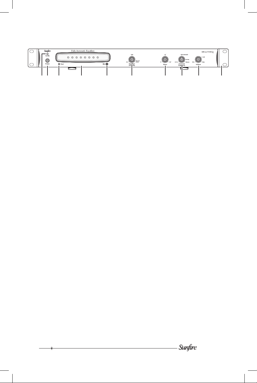
1. Standby LED and
2. Power Switch
Press the power switch in to turn on
the amplier. As a general rule, turn it
on after your preamplier or receiver
is turned on. When you have nished
listening for the night, turn it off before
your preamplier or receiver.
After a period of inactivity (i.e. with no
input signal), the amplier will automatically turn itself to Standby mode, where
it is effectively off. It can however, turn
back on automatically when an audio
input signal is present, if a 12 VDC
trigger voltage is applied to the Trigger
inputs, or if the Start button is pressed.
3. Start button
Press this once to enter the Auto EQ
mode (if the sub is out of Standby
mode). Press and hold it down for
several seconds to enter the Manual
EQ mode. See page 12 for more details on this and the EQ controls.
4. LED display
These LEDs are used during the Auto
EQ and Manual EQ procedures.
5. Microphone Input
This is where you plug in the supplied
linear measurement microphone when
you want to use the Auto EQ mode.
(Only use the supplied microphone.)
6. Equalizer Authority
This control's primary purpose is to
adjust the EQ Authority. During normal
listening, you can adjust the overall EQ
from none (ccw, 0%), to fully equalized
(cw, 100%). For example, if your rst
band has a 6 dB boost, setting this
control to 50% would make it boost
only 3 dB.
This control is also used during the
Manual EQ mode to adjust each of the
four internal EQ bands, and allow you
to add "color" to the sound as desired.
7. Phase Control
This control changes the relative phase
of the subwoofer with respect to your
other speakers. Use this control to help
blend the subwoofer with the rest of
your system. This is accomplished by
adjusting the control in small incre-
ments as you listen for the most bass
at your listening position. As a nal trim,
readjust the Crossover Frequency and
Volume controls after the Phase has
been set.
8. Crossover Frequency
This controls the high frequency cutoff
point. With the control at the 100 Hz
mark, the subwoofer will reproduce
frequencies up to 100 Hz. If the control
is set fully clockwise, the crossover
is bypassed and the subwoofer will
reproduce a frequency range up to
115 Hz. With the control fully counter-
clockwise the subwoofer reproduces a
narrow range, up to 30 Hz.
Amplier Features
6
1 2 3 4 5 6 7 8 9 10
User's Manual
Rotate the crossover frequency control
until the bass sounds natural. If the
mid-bass sounds good but you want
more low bass, turn this control down a
little, then turn the Volume control up by
about the same amount. This increases
the low-bass output while leaving the
mid-bass output the same.
9. Volume
This control lets you match the output
level of the subwoofer to the level
of your satellite/main speakers. The
subwoofer output will increase as this
control is rotated clockwise. When you
have just installed your system, turn
this down rst before turning on your
subwoofer. This will prevent any loud
surprises.
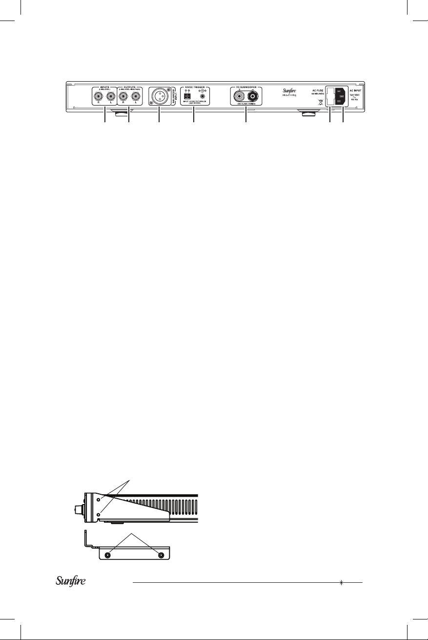
10. Rack Ears
The subwoofer amplier comes with
two rack ears which allow it to be
mounted in a standard 19 inch rack.
Allow one rack space for the amplier,
and one rack space minimum above
and below it for ventilation.
The rack ears are easily tted and
removed using four existing screws as
shown.
11. Line-Level Inputs
Connect these unbalanced inputs with
RCA type patch cords to the line-level
outputs of your receiver or preamp.
If your preamplier or receiver has a
single sub/LFE output, connect it to the
sub amplier’s left input jack (see page
14). There is then no need to use the
right input jack.
If you want to run your main/satellite
speakers full range, use a “Y” adapter
at the preamplier outputs (see page
15). In this way, you can send the
preamplier’s output signal to your
main amplier and to the sub amplier
at the same time.
12. Outputs
Line-level high-pass output signals
are available at these jacks. These
outputs are active whenever a signal
is hooked up to the line-level inputs of
the sub amplier. This crossover is a
passive network with a xed crossover
frequency of 70 Hz and a 6 dB per
octave slope.
We recommend using this high-pass
function with main/satellite speakers
that are small and not designed to
reproduce low frequencies. If your main
speakers are capable of operating full
range, then you will not need to use the
high-pass function.
To use the high-pass outputs, connect
the preamp outs on your preamp/re-
ceiver to the sub amplier’s line level
inputs using good quality RCA type
side screws
bottom screws
7
11 12 13 14 15 16 17
User's Manual
Control Panel Features continued
patch cords. Then connect a second
patch cord from these outputs to the
inputs of your main amplier. This will
allow your main speakers to operate
at frequencies above 70 Hz and the
subwoofer to operate at frequencies
below 70 Hz (see page 16).
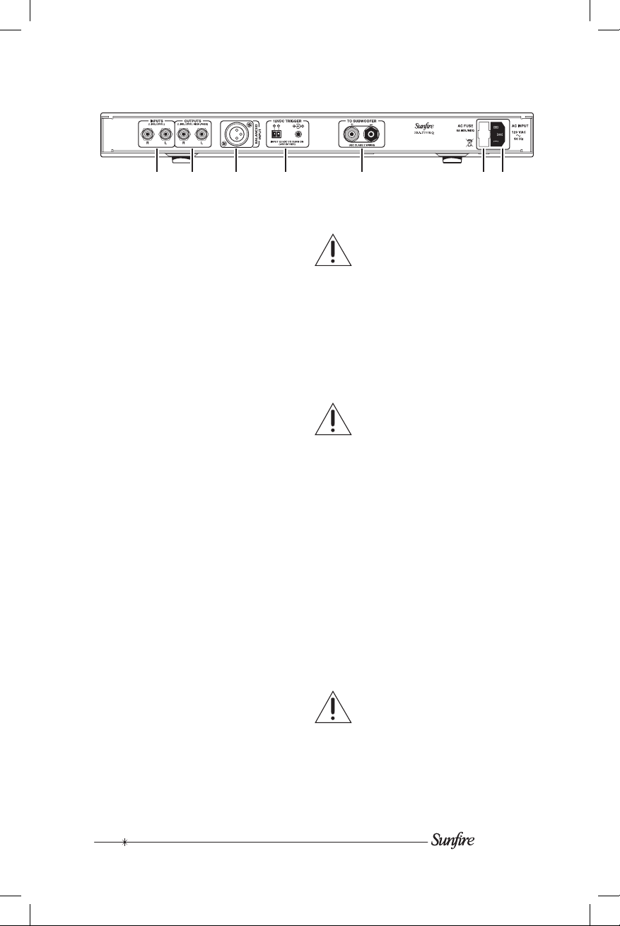
13. Balanced (XLR) Input
Use this balanced input to connect
to the balanced line-level output of a
Home Theater preamplier or other
source. Balanced connections offer
superior noise cancellation over unbalanced connections, so if your preamp
has an XLR sub output, we recommend
that you use it.
14. Trigger Inputs
These two inputs can be used to
automatically turn on the sub amplier.
To do this, connect 12 VDC to either of
these terminals. Some Home Theater
preampliers, such as the Sunre
Theater Grand series, have matching
12 VDC Trigger outputs. When they are
turned on, the subwoofer will turn on.
15. Speaker Level Outputs
This is the connection to the subwoofer.
Use high-quality speaker wire.
The red post is the positive output, and
connects to the positive (red) post of
your subwoofer. The black post is the
negative, and connects to the negative
(black) post of your subwoofer. The
posts can accept bare wire, spade
terminals, and dual or single banana
connectors.
The amplier is designed to
power only the Sunre SubRosa
subwoofer. No other subwoofer or
speaker should be connected, or
this may lead to serious damage to
your equipment.
16. Line Fuse
The subwoofer is supplied with a con-
servative slow-blow type fuse to protect
the electronics.
Always unplug the power cord
before inspecting or changing the
fuse. Never use a fuse with a larger current rating than shown on the
markings next to the fuseholder.
Use a small at screwdriver to pry
out the fuseholder and replace the
fuse.
17. IEC Linecord socket
The sub amplier comes with a detach-
able linecord that connects here.
US (120 VAC) MODEL: Connect
the linecord to the subwoofer before
connecting the other end to an 120
Volt, 60 Hz AC outlet. The outlet must
have a circuit rating of 8 amps or more
(a typical home circuit is rated at 15
amps).
Never plug the US (120 VAC)
Model subwoofer directly into
220-240 Volts AC as this will cause
catastrophic circuit failure.
11 12 13 14 15 16 17
8
 Loading...