

Page 1
Operating Instructions • Warning Information • Parts Breakdown
Some dust created by power sanding,
sawing, grinding, drilling, and other
construction activities contains chemicals
known to cause cancer, birth defects or other
reproductive harm. Some examples of these
chemicals are:
• lead from lead-based paints,
• crystalline silica from bricks
and cement and other masonry
products, and
• arsenic and chromium from
chemically-treated lumber.
Your risk from these exposures varies,
depending on how often you do this type
of work. To reduce your exposure to these
chemicals: work in a well ventilated area,
and work with approved safety equipment,
such as those dust masks that are specially
designed to filter out microscopic particles.
SPECIFICATIONS
Fluid Orifice .................................................................................. 1.3mm
Air Inlet: .......................................................................................... 1/4" NPT
Rec. Max. Inlet Pressure ......................................................................60 PSI
CFM: .......................................................................................... 7.2 at 50 PSI
Nozzle Pressure ...................................................................................47 PSI
Cup Size .............................................................................................1000cc
ALWAYS READ INSTRUCTIONS
BEFORE USING POWER TOOLS
ALWAYS WEAR
SAFETY GOGGLES
WEAR HEARING
PROTECTION
AVOID PROLONGED
EXPOSURE TO VIBRATION
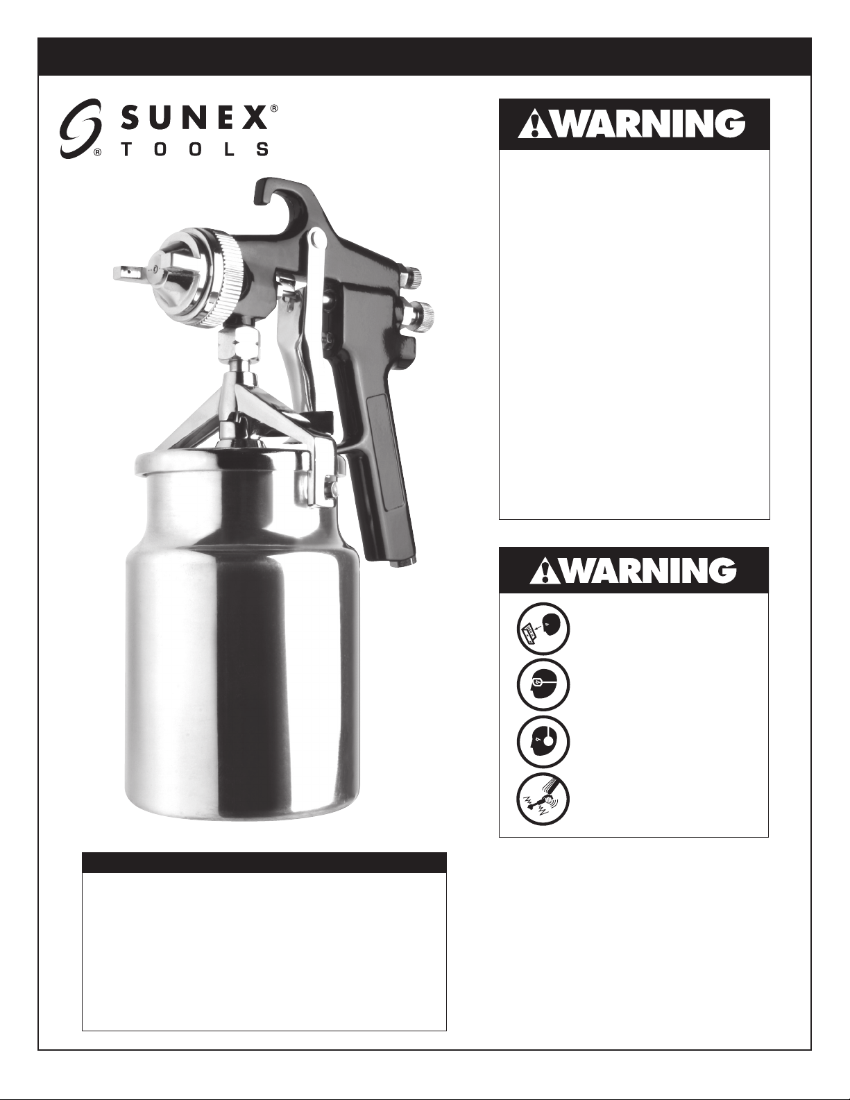
SX70C
Spray Gun
and Cup
SX70C: Parts Breakdown & Operating Manual 1 rev. 04/28/06
Page 2
- FOLLOW THESE RULES FOR SAFE OPERATION!
• During cleaning and flushing, solvents can be
forcefully expelled from fluid and air passages.
Some solvents can cause eye injury.
• Be sure all in the area are wearing
impact-resistant eye and face protection.
• Even small projectiles can injure eyes and
cause blindness.
• Air under pressure can cause severe injury.
Always shut off air supply, drain hose of air
pressure and disconnect tool from air supply
when not in use, before changing accessories or
when making repairs. Never direct air at
yourself or anyone else. Whipping hoses can
cause serious injury. Always check for damaged
or loose hoses and fittings. Never use quick
change couplings at tool. They add weight and
could fail due to vibration. Instead, add a hose
whip and connect coupling between air supply
and hose whip, or between hose whip and
leader hose. Do not exceed maximum air inlet
pressure of 60 PSI.
• Always use tool a safe distance from other
people in work area.
• Maintain tools with care. Keep tools clean and
oiled for best and safest performance. Follow
instructions for lubricating and changing
accessories. Wiping or cleaning rags and other
flammable waste materials must be placed in a
tightly closed metal container and disposed of
later in the proper fashion.
• Do not wear loose or ill-fitting clothing; remove
watches and rings.
• Do not over reach. Keep proper footing and
balance at all times. Slipping, tripping and
falling can be a major cause of serious injury
or death. Be aware of excess hose left on the
walking or work surface.
• Do not force tool. It will do the job better and
safer at the rate for which it was designed.
• Do not abuse hoses or connectors. Never
carry tool by the hose or yank hose to
disconnect from air supply. Keep hoses from
heat, oil and sharp edges. Check hoses for weak
or worn condition before each use, making
certain that all connections are secure.
• High sound levels can cause permanent
hearing loss. Protect yourself from noise.
Noise levels vary with work surface.
Wear ear protection.
• When possible, secure work with clamps or
vise so both hands are free to operate tool.
• Repetitive work motions, awkward positions
and exposure to vibration can be harmful to
hands and arms.
• Avoid inhaling dust or handling debris from
work processes which can be harmful to your
health.
• Operators and maintenance personnel must be
physically able to handle the bulk, weight and
power of this tool.
• This tool is not intended for using in explosive
atmospheres and is not insulated for contact
with electric power sources.
• Solvent and coatings can be highly flammable or
combustible especially when sprayed. Adequate
exhaust must be provided to keep air free of
accumulations of flammable vapors.
• Smoking must never be allowed in the
spray area.
• Fire extinguishing equipment must be present in
the spray area.
• Never spray near sources of ignition such as pilot
lights, welders, etc.
• Halogenated hydrocarbon solvents — for
example, methylene chloride — are not
chemically compatible with the aluminum
that might be used in many system components.
The chemical reaction caused by these
solvents reacting with aluminum can become
violent and lead to an equipment explosion.
Guns with stainless steel fluid passages may
be used with these solvents. However,
aluminum is widely used in other spray
application equipment - such as material pumps,
cups and regulators, valves, etc. Check all other
equipment items before use and make sure they
can also be used safely with these solvents.
Read the label or data sheet for the material
you intend to spray. If in doubt as to whether or
not a coating or cleaning material is compatible,
contact your material supplier.
• Sprayed materials may be harmful if inhaled, or
if there is contact with the skin. Adequate
exhaust must be provided to keep the air free
of accumulations of toxic materials. Use a mask
or respirator whenever there is a chance of
inhaling sprayed materials. The mask must be
compatible with the material being sprayed and
its concentration.
SX70C: Parts Breakdown & Operating Manual 2 rev. 04/28/06
Page 3
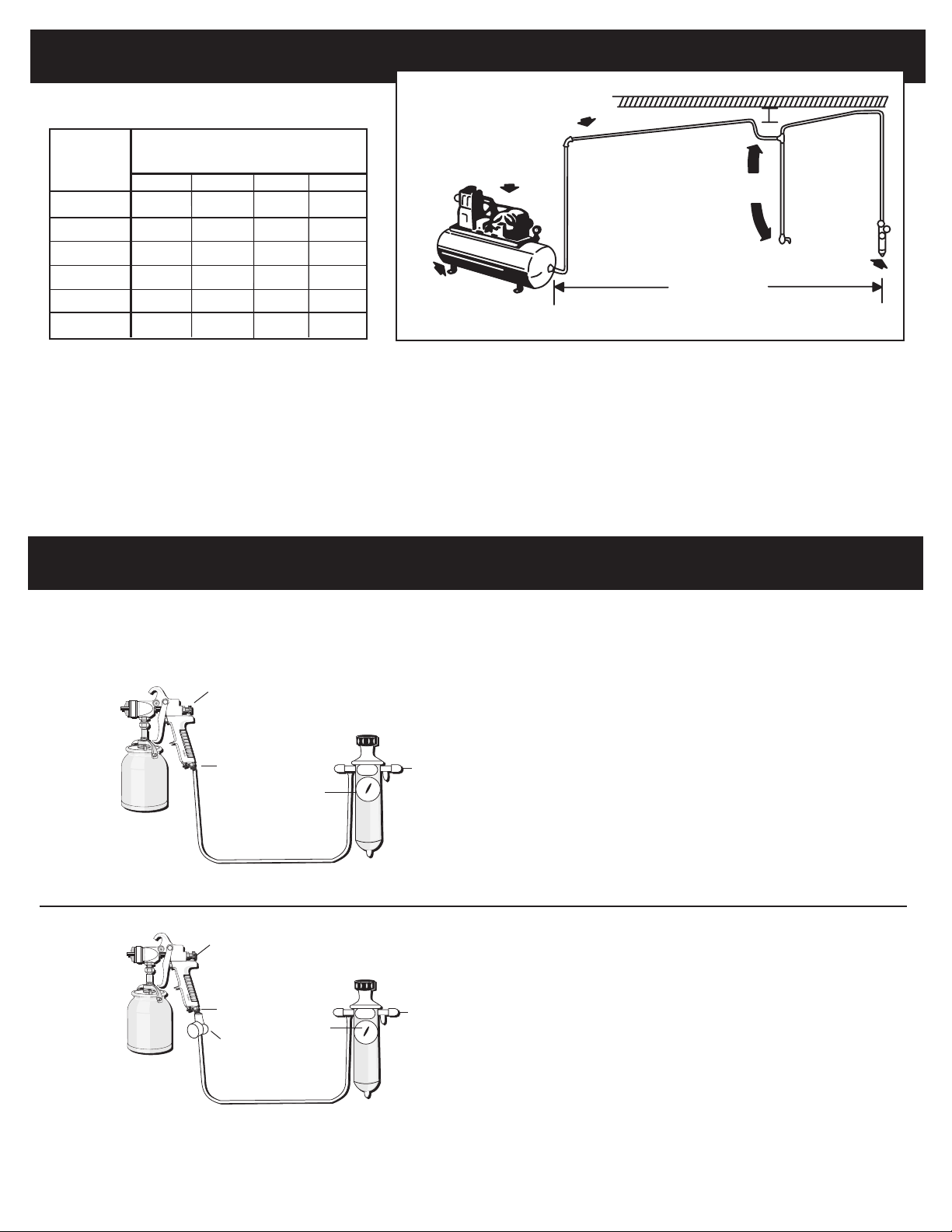
AIR SUPPLY
HVLP
HVLP
Pitch pipe back
toward air receiver
Air
Flow
CFM
10
20
30
40
50
70
Length of Pipe (ft.)
50 100 150 200
1/2"
3/4"
3/4"
1"
1"
1"
3/4"
3/4"
3/4"
1"
1"
1"
3/4"
3/4"
1"
1"
1"
1-1/4"
3/4"
1"
1"
1"
1-1/4"
Compressor Unit
Drain
Install drain at
each low point
Oil & Water
Extractor
25 Feet
or More
Oil and Water Extractor should be at least 25 ft.
from the compressor, farther if possible.
Drain
Never mount oil and water extractor on or near the air compressor.
During compression, air temperature is greatly increased. As the air cools down to room temperature, moisture condenses in the air line, on
its way to the spray gun. Therefore, always mount the oil and water extractor at a point in the air supply system where the compressed air
temperature is lowest.
Drain air lines properly.
Pitch all air lines back towards the compressor so that condensed moisture will flow back into the air receiver where it can be drained off. Each
low point in an air line acts as a water trap. Such points should be fitted with an easily accessible drain. See diagram above.
TYPES OF INSTALLATION
This spray gun is rugged in construction, and is built to yield exceptional value. The life of this product and the efficiency of its
operation depend upon a knowledge of its construction, use and maintenance.
Fluid Control Screw
SIPHON FEED CUP HOOKUP
Air pressure for atomization is regulated at extractor.
Amount of fluid is adjusted by fluid control screw on gun,
viscosity of paint, and air pressure.
Fluid
Siphon Cup
Air Inlet
Atomization
Pressure
Gauge
Air Hose
Fluid Control Screw
Oil and
Water
Extractor
PRESSURE FEED CUP HOOKUP
For fine finishing with limited spraying.
Oil and
Water
Extractor
Air pressure for atomization is regulated at
extractor; fluid pressure at cup regulator. For heavy
fluids and internal mix nozzle spraying, fluid adjusted by
control screw on gun.
Fluid
Siphon Cup
Air Inlet
Cup
Regulator
Atomization
Pressure
Gauge
Air Hose
SX70C: Parts Breakdown & Operating Manual 3 rev. 04/28/06
Page 4
FOR BEST PERFORMANCE,
PLEASE BE SURE TO DO THE FOLLOWING
BEFORE USING THIS TOOL
• Tighten the gun to the cup securely with the nut and fitting supplied.
• Be sure to have the proper air pressure at the gun to operate. Proper air pressure for this tool should not exceed 50 PSI.
• Adjust fluid control screw and spray width adjustment screw to your desired pattern before using on production.
• Clean all parts after use.
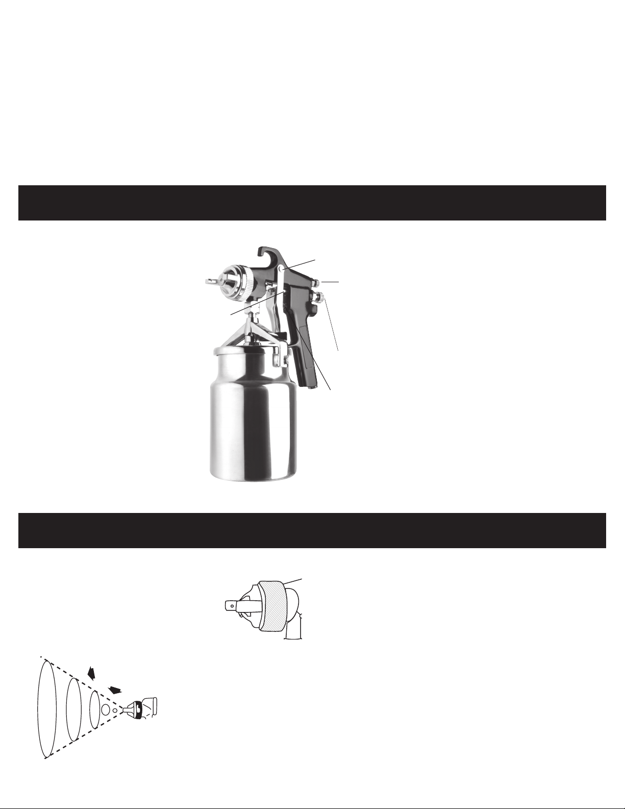
ADJUSTMENTS
Trigger pivot
Spray width
adjustment screw
Fluid needle
packing & nut
Turn right for round,
left for fan.
SPRAYING
In normal use, the nozzle wings are
horizontal as shown here. This provides a
vertical fan-shaped pattern which gives
maximum, even material coverage as the gun
is moved back and forth parallel to the surface
being finished.
Fluid Control Screw
Turn right to decrease
flow, left to increase.
Air
Valve
Set inlet pressure at no more than 60 PSI. For optimum
performance, some materials may spray better at PSI ratings below
60 PSI. If unsure, always test at PSI ratings before using on final
production. Try spray. If it is too fine, decrease the air pressure or
open fluid control screw. If the spray is too thick, close the fluid
control screw. Regulate the pattern width and repeat adjustment of
spray as needed.
Spray pattern may be infinitely adjusted
from round to flat.
SX70C: Parts Breakdown & Operating Manual 4 rev. 04/28/06
Page 5
OPERATION
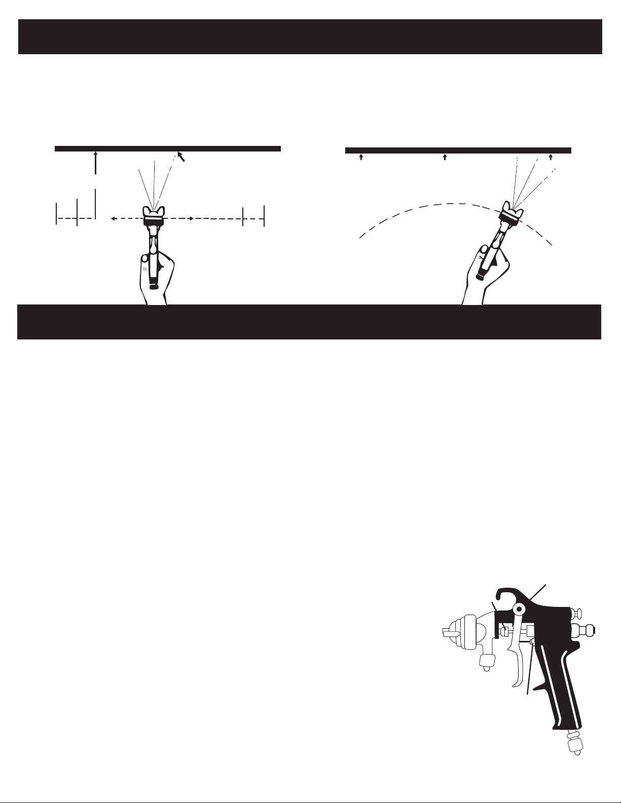
Proper handling of the gun is essential for obtaining a good finish. The
gun should be held at a right angle to the surface being covered, and
moved parallel with it. For precise control of the gun and material, the
trigger should be released before the end of the stroke.
Hold the gun from 6 to 12 inches away from the surface depending
Even and wet coat
6 to 12 inches
Start
stroke
Pull
trigger
RIGHT
Release
trigger
End of
Stroke
on material and atomizing pressure. For a uniform finish, lap each
stroke over the preceding stroke, making sure the spray is smooth
and wet.
Using the lowest possible atomizing air pressure will reduce
overspray and provide maximum efficiency.
Light Coat Heavy Coat
WRONG
CLEANING AND MAINTENANCE
SPRAY GUN
1. Submerge the front end of the gun in solvent just until the
fluid connection is covered.
2. Paint that has built up on the gun should be removed using a
bristle brush and solvent.
3. Never submerge all of the spray gun in solvent because:
• This will dissolve the lubricant in the leather packings and
on wear surfaces, causing them to dry out and resulting in
difficult operation and faster wear.
• Air passages in the gun will become clogged with
dirty solvent.
4. Using a rag moistened with solvent, wipe down the outside of
the gun.
5. Oil gun daily. Use a drop of lightweight machine oil on:
A. fluid needle packing
B. air valve packing
C. trigger pivot point
See Fig. 1 for Location of Above Points.
6. NOTE: Do not soak rubber o-rings or seals in paint thinner.
O-rings and seals can be wiped clean with paint thinner
but soaking can cause these items to
deteriorate over time.
7. Caution: Do not use lubricants
which contain silicone. Silicone
may cause defects in the finish
application.
CAUTION
To avoid cross-threading, all spray gun parts should be screwed
in hand tight initially. If the parts can not easily be turned by
hand, be sure you have the correct parts, unscrew, realign, and
try again. NEVER use excessive force in matching parts.
AIR NOZZLE, FLUID NOZZLE, AIR VALVE ASSEMBLY
1. All nozzles and needles are made to exact standards. They should
be handled carefully.
2. To clean nozzles, immerse them in solvent until any dried
material is dissolved, then blow them clean.
3. Do not use metal or sharp instrument to probe any of the holes in
the nozzles.
4. Air flow should occur before fluid flow when the gun is triggered.
It may be necessary to adjust the fluid control screw to make sure
air flows before fluid.
5. Do not alter the gun in any way.
SIPHON CUP
Turn off air supply. Disconnect
cup from lid. Raise tube out of
material and pull trigger to allow
remaining material to drain
back to the cup. Empty the cup
of material. Clean the cup, lid
and tube. Add some thinner
to cup. Reassemble. Turn on
air supply and spray with
proper cleaning solvent.
Repeat with clean solvent
if necessary. Remove solvent,
disconnect gun, remove air cap
and clean. Wipe gun and cup
with rag dampened
with solvent.
C
A
B
Fig. 1
SX70C: Parts Breakdown & Operating Manual 5 rev. 04/28/06
Page 6
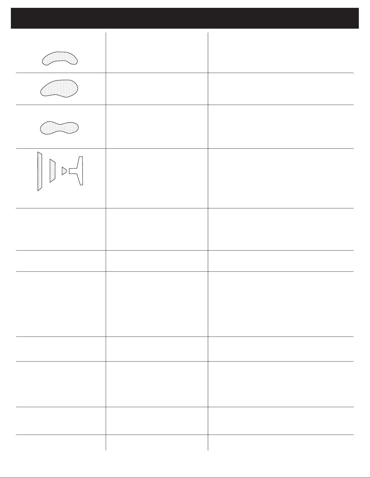
TROUBLESHOOTING
CONDITION
Spitting
PROBLEMSPRAY PATTERN/
One side of nozzle wing is
clogged.
A.) Loose air nozzle.
B.) Material around outside of
air nozzle has dried.
A.) Atomization air pressure is set
too high.
B.) Trying to spray a thin material
in too wide a pattern.
A.) Packing around needle valve
is dried out.
B. Fluid nozzle loosely installed,
or dirt between nozzle
and body.
C.) Loose or defective swivel nut
on siphon cup.
SOLUTION
Soak nozzle in solvent to loosen clog, then blow air through
until clean. To clean orifices use a broom straw or toothpick.
Never try and detach dried material with sharp tool.
A.) Tighten air nozzle.
B.) Take off air nozzle and wipe off fluid tip,
using rag moistened with thinner.
A.) Reduce air pressure.
B.) Increase material control by turning fluid
control screw to left, while reducing spray
width by turning spray width adjustment
screw to right.
A.) Back up knurled nut, put a few drops of
machine oil on packing, re-tighten nut.
B.) Take off fluid nozzle, clean rear of nozzle and
seat in gun body. Replace nozzle and bring in
tight to body.
C.) Tighten or change out swivel nut.
Improper spray pattern.
Unable to get round spray.
Will not spray.
Fluid leakage from
packing nut.
Dripping from fluid tip.
A.) Gun improperly adjusted.
B.) Dirty air cap.
C.) Fluid tip obstructed.
D.) Sluggish needle.
Fan adjustment screw not
seating properly.
A.) No air pressure at gun.
B.) Fluid pressure too low with
internal mix cap and
pressure tank.
C.) Fluid control screw not
open enough.
D.) Fluid too heavy for
suction feed.
A.) Packing nut loose.
B.) Packing worn or dry.
A.) Dry packing.
B.) Sluggish needle.
C.) Tight packing nut.
D.) Worn fluid nozzle or needle.
A.) Readjust gun. Follow instructions carefully.
B.) Clean air cap.
C.) Clean.
D.) Lubricate.
Clean or replace.
A.) Check air supply and air lines.
B.) Increase fluid pressure at tank.
C.) Open fluid control screw.
D.) Thin material or change to pressure feed.
A.) Tighten, but not so tight as to grip needle.
B.) Replace packing or lubricate.
A.) Lubricate.
B.) Lubricate.
C.) Adjust.
D.) For pressure feed, replace with new fluid nozzle
and needle.
Thin, sandy coarse finish.
Thick, dimpled finish
resembling orange peel.
SX70C: Parts Breakdown & Operating Manual 6 rev. 04/28/06
A.) Gun held too far from surface.
B.) Atomization pressure set
too high.
Gun held too close to surface.
A.) Move gun closer to surface.
B.) Adjust atomization pressure.
Move gun further from surface.
Page 7
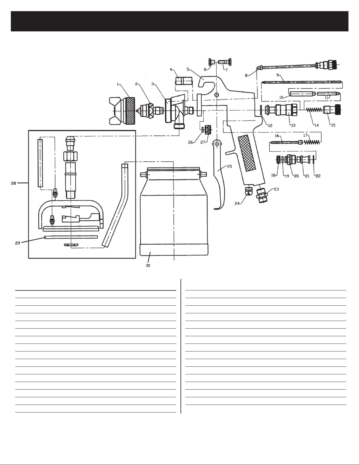
SX70C PARTS BREAKDOWN & PARTS LIST
ITEM NO. PART NO. DESCRIPTION QTY.
1 RS70C01 Air Cap (1.3mm) 1
2 RS70C02 Fluid Nozzle (1.3mm) 1
3 RS70C03 Nozzle Seat 1
4 RS70C04 Two-Headed Screw 1
5 Gun Body 1
6
7
8 RS70C08 Air Valve Adjusting Packing Set 1
9 RS70C09 Needle Assy. (1.3mm) (incl.#10,11) 1
10
11
12
13 RS70C13 Spring Housing 1
14
15 RS70C15 Adjusting Screw 1
16
Only items identified by part numbers are available separately. Items marked with an asterisk (*) are available only in the repair kit, RS70CRK.
SX70C: Parts Breakdown & Operating Manual 7 rev. 04/28/06
Trigger Stud 1
*
Trigger Crossbolt 1
*
Needle Packing Set (included w/ #9)
Needle Adjusting Pole (included w/ #9)
Gasket 1
*
Needle Spring 1
*
Air Valve Stem 1
*
1
1
ITEM NO. PART NO. DESCRIPTION QTY.
17
18 RS70C18 Air Valve Screw Cap 1
19
20 RS70C20 Air Valve Screw I 1
21 RS70C21 Air Valve Screw II 1
22
23 RS70C23 Air Inlet Screw 1
24 RS70C24 Screw 1
25 RS70C25 Trigger 1
26
27 RS70C27 Needle Nut 1
28 RS70C28 Paint Cup Lid Assembly (incl.#29) 1
29 RS70C29 Paint Cup Gasket 1
30 RS70C30 Paint Cup 1
Air Valve Spring 1
*
Gasket 1
*
Air Valve Gasket 1
*
Airproof Ring 1
*
Page 8

LIMITED WARRANTY...
SUNEX INTERNATIONAL, INC. WARRANTS TO ITS CUSTOMERS THAT THE COMPANY’S SUNEX TOOLS® BRANDED
PRODUCTS ARE FREE FROM DEFECTS IN WORKMANSHIP AND MATERIALS.
Sunex International, Inc. will repair or replace its Sunex Tools® branded products which fail to give satisfactory service due to defective
workmanship or materials, based upon the terms and conditions of the following described warranty plans attributed to that specific product.
This product carries a 90 day warranty. During this warranty period, Sunex Tools will repair or replace at our option any part or unit which
proves to be defective in material or workmanship.
Other important warranty information...
This warranty does not cover damage to equipment or tools arising from alteration, abuse, misuse, damage and does not cover any repairs or
replacement made by anyone other than Sunex Tools or its authorized warranty service centers.The foregoing obligation is Sunex Tools’ sole
liability under this or any implied warranty and under no circumstances shall we be liable for any incidental or consequential damages.
Note: Some states do not allow the exclusion or limitation of incidental or consequential damages, so the above limitation or exclusion may
not apply to you. Please contact your local Sunex distributor for proper warranty handling procedures.
If you have any questions about warranty service, please write to Sunex Tools. This warranty gives you specific legal rights and you may also
have other rights which vary from state to state. Repair kits and replacement parts are available for many of Sunex Tools products regardless
of whether or not the product is still covered by a warranty plan.
Shipping Address: Sunex Tools • 315 Hawkins Rd. • Travelers Rest, SC 29690
Mailing Address: Sunex Tools • P.O. Box 4215 • Greenville, SC 29608
SX70C: Parts Breakdown & Operating Manual 8 rev. 04/28/06
Page 9

Instrucciones de operación • Información de advertencia • Desglose de partes
El polvo creado por la lijación eléctrica, la
aserradura, la trituración, la perforación y otras
actividades de construcción contiene químicos
conocidos como causantes de cáncer, defectos
de nacimiento u otros daños a reproducción.
Algunos ejemplos de dichos químicos son:
• El plomo proveniente de pintura con
base de plomo,
• La silica cristalina de ladrillo y cemento
y otros productos de mampostería, y
• El arsénico y el cromio de maderos
químicamente tratados.
El riesgo de dichas exposiciones varía,
dependiendo de la frecuencia con la cual usted
realice este tipo de trabajo. Para reducir su
exposición a dichos químicos: trabaje en una
área bien ventilada y con equipo de seguridad
aprobado, tales como los máscaras anti-polvo,
los que son específicamente diseñados para
filtrar las partículas microscópicas.
LEER SIEMPRE LAS
INSTRUCCIONES ANTES DE
USAR LAS HERRAMIENTAS
NUEMÁTICAS
USAR SIEMPRE ANTEOJOS
PROTECTORES
USAR PROTECCIÓN PARA
LOS OÍDOS
EVITAR EXPOSICIÓN
PROLONGADA A LAS
VIBRACIONES
ESPECIFICACIONES
Orificio de fluidos ........................................................................ 1.3mm
Orificio de entrada de aire: .......................................................1/4" NPT
Presión máxima recomendada del orificio de entrada .................60 PSI
CFM: ............................................................................... 7.2 a los 50 PSI
Presión de la boquilla .................................................................... 47 PSI
Tamaño del vaso ..........................................................................1000cc
SX70C: Desglose de Partes & Manual de Operación 9 rev. 04/28/06
puLVErIZadOra
COn dEpÓSITO
SX70C
pISTOLa
Page 10

-
¡SIGA ESTAS NORMAS PARA UNA OPERACIÓN
SEGURA!
• Durante la limpieza y enjuague a chorro, los
solventes podrían ser expelidos con fuerza por los
conductos de fluidos y aire. Algunos solventes pueden
lesionar los ojos.
• Asegúrese de que todas las personas que se
hallan en el área usen gafas y máscaras de protección
para la cara resistentes al impacto.
• Aun proyectiles pequeños pueden lesionar los
ojos y causar ceguera.
• El aire bajo presión puede causar lesiones graves.
Cierre siempre el suministro de aire, drene
la presión de aire de la manguera y desconecte
la herramienta del suministro de aire cuando no se
la usa, antes de cambiar los accesorios o al hacer
reparaciones. Nunca dirija el flujo de aire
hacia usted o hacia otra persona. El latigazo de la
manguera puede causar una lesión grave. Verifique
siempre que las mangueras y los herrajes no estén
dañados o sueltos. No use nunca acoplamientos de ca
bio rápido en la herramienta, ya que agregan peso y
podrían fallar debido a la vibración. En lugar de esto,
agregue un latiguillo de manguera y conecte el
acoplamiento entre el suministro de aire y el latiguillo de
manguera o entre el latiguillo de manguera y la manguera
principal. No exceda la presión máxima de aire de 60 PSI.
• Use siempre la herramienta a una distancia
segura de las otras personas que están en el
área de trabajo.
• Cuide siempre las herramientas. Manténgalas
limpias y aceitadas para asegurar el mejor y
más seguro rendimiento. Siga las instrucciones para
lubricar y cambiar los accesorios. Los paños
para repasar o limpiar y otros materiales inflamables de
desecho deberán colocarse en un recipiente de metal
herméticamente cerrado y desecharse luego en forma
adecuada.
• No use ropa demasiado holgada o suelta,
quítese los relojes y anillos.
• No se esfuerce en alcanzar lo que está fuera del
alcance. Mantenga el equilibrio en todo momento.
Resbalar, tropezar y caer puede ser una de las
principales causas de lesiones graves o la muerte.
Fíjese si hay manguera sobrante que esté
obstruyendo el camino o la superficie de trabajo.
• No fuerce la herramienta. Funcionará mejor y
en forma más segura a la velocidad de trabajo
para la cual fue diseñada.
• No maltrate las mangueras o los conectores. No transporte
nunca la herramienta por la manguera ni tire de
ella para desconectarla de la fuente de potencia.
Mantenga las mangueras al jadas del calor, del
aceite y de los bordes afilados. Antes de cada uso,
verifique que la mangueras no estén gastadas ni
debilitadas y asegúrese de que todas las conexiones
están firmes.
• Los niveles altos de sonido pueden causar una
pérdida de audición permanente. Protéjase contra
el ruido. Los niveles de ruido varían con la
superficie de trabajo. Use protectores para los
oídos.
• Siempre que sea posible asegure el trabajo con
abrazaderas o un torno, para tener ambas
manos libres para operar la herramienta.
• Los movimientos repetitivos de trabajo, las
posturas incómodas y la exposición a la vibración
pueden ser dañinos para las manos y los
brazos.
• Evite inhalar el polvillo o manipular desechos de
los procesos del trabajo, que pueden ser
nocivos para su salud.
• Los operadores y el personal de mantenimiento
deben tener capacidad física para manejar el
tamaño, el peso y la fuerza de esta
herramienta.
• Esta herramienta no debe usarse en
atmósferas explosivas. No está aislada para el
contacto con fuentes de corriente eléctrica.
• Los solventes y los recubrimientos
pueden ser altamente inflamables o combustibles,
especialmente cuando se los rocía. Debe proveerse un
escape adecuado para evitar la acumulación de vapores
inflamables en el aire.
• No se permitirá nunca fumar en el área de rociado.
• Deberá haber un equipo de extinción de incendios en
el área de rociado.
• No deberá rociarse nunca cerca de áreas de encendido
como pilotos, soldadores, etc.
• Los hidrocarburos solventes halogenados — como por
ejemplo el cloruro de metileno, no son químicamente
compatibles con el aluminio que podría
usarse en muchos componentes de sistemas.
La reacción química causada cuando estos
solventes reaccionan al aluminio puede ser violenta y
producir una explosión en el equipo. Podrá
usarse pistolas pulverizadoras con conductos de acero
inoxidable con estos solventes. No obstante, el aluminio
se usa ampliamente en otro tipo de equipo de
rociado como las bombas, recipientes y reguladores
del matrial, válvulas, etc. Examine todos
los otros artículos del equipo antes del uso y asegúrese
de que puedan también usarse con seguridad con estos
solventes. Lea la etiqueta o la hoja de información
para el material que va a rociar. Si tiene alguna duda
acerca de si un recubrimiento o material de limpieza es
compatible, póngase en contacto con el proveedor de
sus materiales.
• Los materiales rociados pueden ser dañinos si se
inhalan o si entran en contacto con la piel. Debe proveerse
un escape adecuado para evitar la acumulación de
vapores inflamables en el aire. Use una máscara o un
respirador cuando exista la posibilidad de inhalar
materiales rociados. La mascara deberá ser
compatible con el material que se rocía y su
concentración.
SX70C: Desglose de Partes & Manual de Operación 10 rev. 04/28/06
Page 11

HVLP
SUMINISTRO DE AIRE
HVLP
Escuadre el tubo hacia
el receptor de aire
Pies cúbicos
por minuto
(CFM) de Flujo
de aire
10
20
30
40
50
70
Nunca monte el extractor de aceite y agua en o cerca del compresor de aire.
Durante la compresión, la temperatura del aire aumenta considerablemente. A medida que el aire se enfría a
temperatura ambiente, la humedad se condensa en la tubería de aire, hacia la pistola pulverizadora. Por lo tanto siempre debe
montarse el extractor de aceite y agua en un punto del sistema de suministro de aire donde la temperatura del aire
comprimido sea la más baja.
Drene correctamente las tuberías de aire.
Escuadre todas las tuberías de aire hacia el compresor para que la humedad condensada fluya de regreso al receptor de aire donde puede
drenarse. Cada punto bajo en una tubería de aire hace de colector de agua. Deberá adaptarse un drenaje fácilmente accesible a esos puntos.
Ver el diagrama arriba.
Longitud del tubo (pies)
50 100 150 200
1/2"
3/4"
3/4"
1"
1"
1"
3/4"
3/4"
3/4"
1"
1"
1"
3/4"
3/4"
1"
1"
1"
1-1/4"
3/4"
1"
1"
1"
1-1/4"
Drenaje
Unidad de
compresión
Instalar drenaje en
cada punto bajo
Aceite y agua
Extractor
Drenaje
25 pies o más
El extractor de aceite y aqua deberá estar a una distancia
de al menos 25 pies del compresor, más lejos si es posible.
TIPOS DE INSTALACIÓN
Esta pistola pulverizadora es resistente en su construcción y fue manufacturada para proporcionar un valor excepcional. La vida útil de este
producto y la eficiencia de su operación depende de un conocimiento de su construcción, uso y mantenimiento.
Taza Flúida
Del Sifón
Taza Flúida
Del Sifón
Tornillo de control
del fluido
Admisión de aire
Indicador de
presión de
atomización
Manguera neumática
Tornillo de control
del fluido
Admisión de aire
Indicador de
presión de
Regulador
del vaso
atomización
Manguera neumática
Extractor
de aceite
y agua
Extractor
de aceite
y agua
CONEXIÓN PARA VASO DE
ALIMENTACIÓN POR SIFÓN
La presión de aire para la atomización está regulada en
el extractor. Se ajuste la cantidad de fluidos por la perilla
reguladora de fluidos en la pistola, la viscosidad de la
pintura y la presión de aire.
CONEXIÓN PARA VASO DE
ALIMENTACION A PRESIÓN
Para acabados finos con aspersión limitada.
La presión de aire para la atomización se regula en el
extractor; la presión de fluidos se regula por el regulador
del vaso. Para fluidos espesos y la aspersión de boquilla
de mezcla interna, los fluidos se ajusten por la perilla
reguladora en la pistola.
SX70C: Desglose de Partes & Manual de Operación 11 rev. 04/28/06
Page 12

HVLP
PARA OBTENER EL MAYOR RENDIMIENTO,
POR FAVOR ASEGÚRESE DE HACER
LO SIGUIENTE ANTES DE USAR ESTA
HERRAMIENTA
• Ajuste firmemente la pistola al recipiente con la tuerca y el herraje provistos.
• Asegúrese de que tiene la presión de aire correcta en la pistola al operarla. La presión de aire correcta para esta herramienta deberá
ser 50 PSI para laca y 60 PSI para esmalte.
• Ajuste el tornillo de control del fluido y el tornillo de ajuste del ancho del rociado al patrón que desea antes de usarlo en
producción.
• Limpie todas las partes después del uso.
RÉGLAGES
El punto de pivote del gatillo
Rociado con tornillo de ajuste
Girarlo hacia la derecha para rociar en
Embalaje y tuerca de aguja
para fluidos
redondo, hacia la izquierda para
rociar en abanico.
ROCIADO
En el uso normal, las orejetas de la boquilla están horizontales como se muestra aquí.
Esto provee un patrón vertical en forma
de abanico que brinda la máxima
cobertura pareja del material al moverse la pistola
de un lado a otro paralelamente a la superficie
que recibe el acabado.
Tornillo de control del fluido
Girarlo hacia la derecha para
disminuir el flujo, hacia la
izquierda para aumentarlo.
Válvula
de aire
Ajuste la presión de atomización en no más de 50 PSI.
Para obtener un rendimiento óptimo, algunos materiales
podrán rociarse mejor debajo de 50 PSI. Si no está seguro,
pruebe siempre las capacidades de PSI antes de usarla en
producción final. Pruebe el rociado. Si es demasiado fino, disminuya la
presión de aire o abra el tornillo de control del fluido. Si el
rociado sale muy grueso, cierre el tornillo de control del fluido.
Regule el ancho del patrón y repita el ajuste del rociado como sea
necesario.
El patrón de rociado puede ajustarse
infinitamente del redondo al plano.
SX70C: Desglose de Partes & Manual de Operación 12 rev. 04/28/06
Page 13

OPERACIÓN
Para obtener un buen acabado, es esencial manejar
correctamente la pistola. La pistola debe sujetarse formando ángulo
recto con la superficie que se está cubriendo y moverse paralela a
ésta. Para lograr un control preciso de la pistola y el material, deberá
soltarse el gatillo antes de terminar la pasada.
Sostenga la pistola de 6 a 12 pulgadas de distancia de la superficie, según el material que se use y la presión de atomización. Para
obtener un acabado uniforme, traslape cada pasada sobre la pasada
precedente, asegurándose de que el rociado salga suave y mojado.
Si se usa la presión de atomización más baja posible, se reducirá el
exceso de rociado y se obtendrá una máxima eficiencia.
Capa Ligera Capa Pesada
Comenzar
la pasada
CORRECTO
6 a 12 pulgadas
Apretar el
gatillo
Capa pareja y mojada
Soltar el
gatillo
Fin de la
pasada
LIMPIEZA Y MANTENIMIENTO
PISTOLA PULVERIZADORA
1. Sumerja el extremo delantero de la pistola en solvente justo
hasta cubrir la conexión al fluido.
2. Debe removerse la pintura acumulada en la pistola usando
un cepillo de cerda y solvente.
3. Nunca sumerja la pistola pulverizadora entera en el
solvente porque:
• Esto puede disolver el lubricante en las empaquetaduras de
cuero y en las superficies de desgaste, haciendo que se
resequen, dificultando la operación y apres rando el desgaste.
• Los conductos de aire de la pistola quedarán atascados
con el solvente sucio.
4. Usando un paño humedecido con solvente, repase
la parte externa de la pistola.
5. Aceite diariamente su pistola. Use una gota de
aceite ligero para maquinaria en:
A. la empaquetadura de la aguja del fluido
B. la empaquetadura de la válvula de aire
C. el punto de pivote del gatillo
Vea la Fig. 1 para la ubicación de los puntos mencionados.
6. NOTA: No remoje los anillos en “O” o juntas de goma en el diluidor
de pintura. Los anillos en “O” y las juntas se pueden enjuagar con
diluidor de pintura, sin embargo, con el tiempo, el remojo puede causar el deterioro de estos artículos.
7. Precaución: No use lubricantes que contienen siliconas. Las
siliconas pueden causar defectos en la aplicación del
acabado.
PRECAUCIÓN
Para evitar la cruce de hilos, todas las partes de la pistola
pulverizadora deben ser atornilladas apretadamente a mano en primer
estancia. Si no se pueden ajustar las partes fácilmente a mano, asegúrese
que usted tenga las piezas correctas, destorníllelas, realinéelas e intente
de nuevo. NUNCA use fuerza excesiva en las alineación de las partes.
BOQUILLA DE AIRE, BOQUILLA DE FLUIDO,
MONTAJE DE LA VÁLVULA DE AIRE
1. Todas las boquillas y agujas se fabrican conforme a
normas exactas. Deberán manipularse con cuidado.
2. Para limpiar las boquillas, sumérjalas en solvente hasta
que se haya disuelto el material reseco, luego séquelas con
soplador.
3. No use instrumentos de metal o afilados para hurgar en
alguno de los orificios de las boquillas.
4. Cuando se dispara el gatillo de la pistola el flujo de
aire deberá salir antes que el flujo de fluido. Puede ser
necesario ajustar el tornillo de control del fluido para
asegurar que el aire fluya antes del fluido.
5. No modifique la pistola de ninguna manera.
EL VASO PARA SIFÓN
Apague el abastecimiento de aire.
Desconecte el vaso de la tapa.
Saque el tubo del material y apriete
el gatillo de la pistola para permitir
que el material restante se vacíe en
el vaso. Vacíe cualquier material del
vaso. Limpie el vaso, la tapa y el tubo.
Agregue un poco de diluidor de
pintura en el vaso. Reensámblelo
de nuevo. Prenda el abastecimiento
de aire y pulverice con el disolvente
adecuado para limpieza. Repita
con disolvente limpio según sea
necesario. Quite el disolvente,
desconecte la pistola, quite la
tapa de aire y límpiela. Enjuague
la pistola y el vaso con un trapo
remojado con disolvente.
MAL
C
A
B
Fig. 1
SX70C: Desglose de Partes & Manual de Operación 13 rev. 04/28/06
Page 14

LOCALIZACIÓN Y CORRECCIÓN DE FALLAS
ROCIADO/ESTADO
Pequeñas salpicaduras
(escupidas) de fluido
PROBLEMAPATRÓN DE
Un lado de la orejeta de la
boquilla está atascado.
A.) Boquilla de aire suelta.
B.) El material alrededor de la parte
externa de la boquilla está reseco.
A.) La presión de aire de atomización
está ajustada muy alta.
B.) Intentando rociar un material fino
en un patrón demasiado amplio.
A.) La empaquetadura alrededor de la
válvula de la aguja está reseca.
B. La boquilla del fluido ha que dado
suelta, o hay suciedad entre la
boquilla y el cuerpo.
C.) Tuerca giratoria suelta o defectuosa
en el casquillo del sifón.
SOLUCIÓN
Remoje la boquilla en solvente para aflojar el atascamiento, luego
sople aire por la boquilla hasta que quede limpia. Para limpiar los
orificios use una pajita de escoba o un escarbadientes. No intente
nunca despegar material reseco con una herramienta afilada.
A.) Ajuste la boquilla de aire.
B.) Saque la boquilla de aire y pásele un paño,
humedecido con diluyente por la punta.
A.) Reduzca la presión de aire.
B.) Aumente el control del material girando el tornillo de
control del fluido hacia la izquierda, mientras reduce
la amplitud del rocío ajustando el tornillo hacia la
derecha.
A.) Mueva la tuerca estriada hacia atrás, coloque unas
gotas de aceite para maquinaria en la empaquetadura,
vuelva a ajustar la tuerca.
B.) Saque la boquilla del fluido, limpie la parte trasera de la
boquilla y el asiento en el cuerpo de la pistola. Vuelva a
colocar la boquilla y afírmela bien al cuerpo.
C.) Ajuste o cambie la tuerca giratoria.
Patrón de rociado incorrecto.
Imposible obtener un rociado en
redondo.
No aspersionará
Fuga de fluido de la tuerca de
empaquetadura.
Goteo de la punta del fluido.
A.) Pistola incorrectamente ajustada.
B.) Cubierta del aire sucia.
C.) Punta del fluido obstruida.
D.) Aguja lenta.
El tornillo de ajuste del ventilador no
está bien asentado.
A.) No hay presión de aire en la pistola.
B.) La presión del fluido está demasiado
baja con la cubierta de mezcla
interna y el tanque de presión.
C.) El tornillo de control del fluido no
está suficientemente abierto.
D.) El fluido es demasiado pesado para
alimentación por succión.
A.) Tuerca de empaquetadura suelta.
B.) Empaquetadura gastada o reseca.
A.) Empaquetadura reseca.
B.) Aguja lenta.
C.) Tuerca de empaquetadura muy
ajustada.
D.) Boquilla o aguja del fluido gastada.
A.) Reajuste la pistola. Siga cuidadosamente las instrucciones.
B.) Limpie la cubierta del aire.
C.) Limpie.
D.) Lubrique.
Límpielo o reemplácelo.
A.) Verifique el suministro de aire y las tuberías de aire.
B.) Aumente la presión del fluido en el tanque.
C.) Abra el tornillo de control del fluido.
D.) Material delgado o cambia a alimentación a presión.
A.) Ajuste pero no tan firmemente que agarre la aguja.
B.) Reemplace o lubrique la tuerca de empaquetadura.
A.) Lubrique.
B.) Lubrique.
C.) Ajuste.
D.) Para la alimentación a presión, reemplácela con
una nueva boquilla y aguja del fluido.
Acabado delgado, arenoso, áspero.
Acabado grueso, poroso, semejante
a una cáscara de naranja.
SX70C: Desglose de Partes & Manual de Operación 14 rev. 04/28/06
A.) Se mantiene la pistola demasiado
lejos de la superficie.
B.) La presión de atomización está
ajustada muy alta.
Se mantiene la pistola demasiado cerca
de la superficie.
A.) Mueva la pistola más cerca de la superficie.
B.) Ajuste la presión de atomización.
Mueva la pistola más lejos de la superficie.
Page 15

GARANTÍA LIMITADA
SUNEX INTERNATIONAL, INC., LE GARANTIZA A SUS CLIENTES QUE LAS HERRAMIENTAS Y PRODUCTOS
CON LA MARCA DE LA EMPRESA SUNEX TOOLS NO CONTIENEN DEFECTOS EN SU MANO DE OBRA NI
MATERIAS PRIMAS.
Sunex International, Inc., reparará o sustituirá sus productos con la marca Sunex Tools® que reflejen fallas en el funcionamiento satisfactorio
debido a que la mano de obra o las materias primas estén defectuosas, tomando como base las cláusulas y condiciones de los planes de
garantía descritos a continuación y asignados a ese producto específico. Este producto tiene una garantía de noventa días. Durante ese
periodo de garantía, Sunex Tools reparará o sustituirá, como así opte por hacerlo, cualquier componente o unidad que se compruebe tener
decectos en su materia prima o mano de obra.
Otra importante información de la garantía...
Esta garantía no cubre ningún daño al equipo o herramientas, si este surge como resultado de su alteración, abuso, o mal uso o daños ni
tampoco cubre las reparaciones o reposiciones hechas por cualquier persona ajena a los centros de servicio de garantía autorizados y que
no sean de Sunex Tools. La obligación antes mancionada queda bajo la responsabilidad exclusiva de Sunex Tools® según se menciona o
de cualquier garantía implícita y bajo ninguna circunstancia quedará bajo su responsabilidad cualquier garantía implícita ya bajo ninguna
circunstancia quedará bajo su responsabilidad cualquier daño incidental o consecuencial.
Note: Algunos estados no permiten la exclusión o limitación de los daños incidentales o consecuenciales, por lo tanto la limitación o
exclusión arriba mencionada quizá no pudiera serle pertinente a usted. Devuelva el equipo o componentes a Sunex Tools, un centro de
servicio de garantía autorizado, con elflete pagado. Asegúres haber incluido su nimbre y dirección, la evidencia de la fecha de adquisición
y la descripción del defecto que se sospeche tener. Si tiene alguna duda relacionada con elservicio de garantía, por favor escríbale a Sunex
Tools. Esta garantía le concede derechos jurídicos específicos y quizá otros derechos que varían de un estado a otro, Sunex Tools tiene a
su disposición los juegos de reparación y refacciones de repuesto para muchos de sus productos, sin importar si el producto continúe o no
bajo el plan de la garantía.
DIRECCIÓN A EMBARCARSE: Sunex Tools • 315 Hawkins Rd. • Travelers Rest, South Carolina 29690
DIRECCIÓN DE CORREOS: Sunex Tools • P.O. Box 4215 • Greenville, South Carolina 29608
SX70C: Parts Breakdown & Operating Manual 15 rev. 04/28/06
Page 16

Instructions d'utilisation • Avertissements • Liste des pièces
Certains types de poussières produites par le
sablage, le sciage, le meulage et d'autres
activités de construction contiennent des
produits chimiques cancérigènes, qui causent des
anomalies congénitales ou d'autres dangers pour
la reproduction. Parmi ces produits chimiques on
compte :
• le plomb des peintures à base de plomb,
• la silice cristalline des briques et du ciment
et d'autres
produits de maçonnerie, et
• l'arsenic et le chrome du bois traité
chimiquement.
Les risques associés à ces expositions varient
selon la fréquence et le type de travail. Afin de
réduire votre exposition à ces produits chimiques
travailler dans un endroit bien ventilé, avec de
l'équipement de sécurité approuvé, comme des
masques antipoussières conçus spécialement
pour filtrer les particules microscopiques.
SPÉCIFICATIONS
Orifice du fluide : .......................................................................... 1,3mm
Entrée d'air : ............................................................................ 1/4" NPT
Entrée de pression maximum recommandée : ............................. 60 PSI
pi3/min : ..............................................................................7,2 @ 50 PSI
Pression de la buse : ..................................................................... 47 PSI
Taille du godet ..............................................................................1000cc
LEA SIEMPRE LAS INSTRUCCIONES
ANTES DE USAR HERRAMIENTAS
NEUMÁTICAS.
USE SIEMPRE GAFAS
DE SEGURIDAD.
USE PROTECCIÓN
PARA LOS OÍDOS.
EVITE EXPONERSE
PROLONGADAMENTE
A LAS VIBRACIONES
SX70C
pISTOLET À
pEInTurE
aVEC rÉSErVOIr
SX70C: Vue éclatée des pièces et mode d’emploi 16 rev. 04/28/06
Page 17

-
FONCTIONNEMENT SÉCURITAIRE!
VEUILLEZ SUIVRE LES RÈGLES CI-DESSOUS POUR UN
• Lors du nettoyage et de la purge, des solvants
peuvent être expulsés avec force par les conduits d’air et
de liquide. Certains solvants peuvent causer des
blessures aux yeux.
• Assurez-vous que toutes les personnes autour
ont un protecteur résistant au choc pour le visage
et les yeux.
• Même les plus petits projectiles peuvent causer des
blessures aux yeux ou la cécité.
• L’air sous pression peut causer de graves blessures.
Toujours fermer l’alimentation d’air, enlever la pression
dans le tuyau d’air et débrancher l’outil de toute source
d’alimentation lorsqu’il n’est pas utilisé, lors d’un
changement d’accessoire ou lors de réparations. Ne
jamais diriger le jet d’air vers vous ou quelqu’un d’autre.
Les boyaux flexibles peuvent causer de graves
blessures. Toujours s’assurer qu’il n’y a pas de pièces
endo magées ou desserrées. Ne jamais utiliser de
raccord rapide directement du côté de l’outil. Ils ajoutent
du poids et pourraient causer un mauvais fonctionnement
à cause des vibrations. Ajoutez plutôt un boyau flexible
et un raccord entre l’alimentation d’air et le boyau
flexible, ou entre le boyau flexible et le tuyau d’arrivée.
Ne pas dépasser 50 psi de pression d’air.
• Toujours conserver une distance sécuritaire entre vous
et les autres employés.
• Entretenir les outils avec soin. Garder les outils bien huilés
et propres pour obtenir les meilleures performances
sécuritaires Bien suivre les directives pour la
lubrification et les changements d’accessoires. Les
chiffons et les autres déchets inflammables doivent être
mis dans un contenant de métal étanche et jeté ensuite
de façon adéquate.
• Ne pas porter de vêtement ample, ou malajusté, enlever
montre et bagues.
• Garder l’équilibre. Conserver un bon équilibre en
tout temps. Les faux pas, les chute et les pertes
d’équilibre sont les principales causes de décès et de
blessures graves. Faire attention au surplus de boyau
par terre ou sur la surface de travail.
• Ne pas forcer l’outil. Il fera un meilleur travail, de façon
plus sécuritaire, s’il est utilisé comme il se doit.
• Ne pas faire mauvais usage des boyaux et des raccords.
Ne jamais transporter l'outil en tenant le boyau ou tirer
dessus pour le débrancher de l'alimentation électrique.
Tenir les boyaux loin des sources de chaleur, de l’huile et
des bords tranchants. Avant chaque utilistion, rechercher
les signes de bris ou d’usure des boyaux, assurez-vous
que tous les raccords sont bien fixés.
• Un niveau sonore élevé peut causer une perte d’audition
permanente. Protégez-vous du bruit. Le niveau sonore
peut varier en raison de la surface de travail. Porter une
protection auditive.
• Lorsque c’est possible, fixer la pièce à travailler à l’aide
de serre-joint ou d’un étau, ceci vous permettra d’utiliser
vos deux mains pour manipuler l’outil.
• Les mouvements répétitifs, des positions inconfortables
et une exposition aux vibrations peuvent causer des
dommages aux bras et aux mains.
• Éviter de respirer la poussière ou de manipuler des débris
provenant du travail, ceux-ci peuvent être dangereux pour
votre santé.
• Les opérateurs et le personnel d’entretien doivent être
phsiquement capables de supporter la masse, le poids et
la puissance de cet outil.
• Cet outil n’est pas conçu pour être utilisé dans les
atmosphères explosives et il n’est pas isolé pour les
contacts avec des sources d’alimentation électrique.
• Les solvants et les enduits peuvent s’enflammer
facilement ou exploser surtout lors de la pulvérisation.
Une ventilation adéquate doit être utilisée pour éviter
l’accumulation de résdus combustibles.
• Ne jamais fumer dans les locaux de pulvérisation.
• Des équipements de protection contre les incendies
doivent être disponibles dans les locaux de
pulvérisation.
• Ne jamais pulvériser près des sources d’inflammation
comme des veilleuses, appareil de soudure, etc.
• Les solvants d’hydrocarbures halogénés — par exemple, le
chlorure de méthylène — ne sont pas
chimiquement compatibles avec l’aluminium qui peut
être utilisé pour plusieurs composants de systèmes. La
réaction chimique causée par la réaction des solvants et
de l’aluminium peut être violente et mener à une
explosion de l’équipement. Les pistolets avec des
canalisations en acier inoxydable peuvent être
utilisés avec ces solvants. Cependant, l’aluminium est
très utilisé pour les autres équipements de pulvérisation
tels que les pompes, les godets et les valves.
Vérifier toutes les autres pièces d’équipement avant
l’utilisation et assurez-vous qu’elles peuvent être utilisées
en toute sécurité avec ces solvants. Bien lire
l’étiquette et la fiche technique du produit à pulvériser. Si
vous avez des doutes sur la compatibilité des enduits ou
des produits de nettoyage, veuillez contacter le
fournisseur du produit.
• Les produits à pulvériser peuvent nocifs s’ils
sont inhalés, ou s’ils entrent en contact avec la peau.
Une ventilation adéquate doit être utilisée pour éviter
l’accumulation de substances toxiques. Utiliser un
masque ou un appareil de protection respiratoire toutes
les fois qu’il y a une chance de respirer des produits de
pulvérisation. Le masque doit être adapté au produit
pulvérisé ainsi qu’à se concentration.
SX70C: Parts Breakdown & Operating Manual 17 rev. 04/28/06
Page 18

ALIMENTATION D'AIR
HVLP
HVLP
Débit
d'air
PCM
10
20
30
40
50
70
50 100 150 200
1/2"
3/4"
3/4"
1"
1"
1"
Longueur
du tuyau (pi)
3/4"
3/4"
3/4"
1"
1"
1"
3/4"
3/4"
1"
1"
1"
1-1/4"
3/4"
1"
1"
1"
1-1/4"
Drain
Placer le tuyau versle
réservoir d’air comprimé
Compresseur
Le séparateur eau/huile doit être à une distance d’au moins
7,6 m (25pi), et même plus loin du compresseur si possible.
Installer un drain à
chaque point bas
7,6 m (25 pi)
ou plus
Ne jamais installer un séparateureau/huile sur un compresseur d'air ou près de celui-ci.
Pendant la compression, la température de l’airaugmente beaucoup. Lorsque l’air retourne à la température ambiante, l’humidité se condense dans la canalisation d’air, en direction
du pistolet pulvérisateur. Par conséquent, il faut toujours installer le séparateur eau/huile à un endroit du sytème d’arrivée d’air où la température de l’air est la plus basse.
Vidanger adéquatement les canalisations d’air.
Envoyer les canalisations d’air vers le compresseur pour que le condensat retourne vers le réservoir d’air comprimé où il sera évacué. Chaque point bas le long de la canalisation
d’air emprisonne l’eau. Ces points bas doivent être raccordés à un drain accessible facilement. Voir le schéma ci-dessus.
TYPES D'INSTALLATION
Ce pistolet pulvérisateur est de construction robuste, et est bâtit pour offrir un rendement exceptionnel. La durée de vie de ce produit
et l’efficacité de son fonctionnement dépendent des connaissances de sa construction, son utilisation et son entretien
Tasse Liquide
De Siphon
Tasse Liquide
De Siphon
Vis de contrôle
du liquide
Orifice de ventilation
Indicateur de
pression de
pulvérisation
Boyau d’air
Vis de contrôle
du liquide
Orifice de ventilation
Indicateur de
Régulateur
du godet
pression de
pulvérisation
Boyau d’air
Séparateur
eau/huile
Séparateur
eau/huile
BRANCHEMENT DE L'ALIMENTATION
DU GODET DU SIPHON
La pression d’air pour l’atomisation est régularisée à
l’extracteur. La quantité de fluide est ajustée par les vis
d’ajustement du fluide, de la viscosité de la peinture et de
la pression d’air, situées sur le pistolet
BRANCHEMENT DE L’ALIMENTATION
DE LA PRESSION DU GODET
Pour un fini fin avec un jet limité.
La pression d’air pour l’atomisation est régularisée à
l’extracteur; la pression du fluide au régulateur du godet.
Pour des jets de fluides lourds et de buse à mélange interne,
le fluide est ajusté par la vis d’ajustement située sur le
pistolet.
SX70C: Vue éclatée des pièces et mode d’emploi 18 rev. 04/28/06
Page 19

HVLP
POUR OBTENIR DE MEILLEURS RÉSULTATS,
ASSUREZ-VOUS DE RESPECTER LES ÉTAPES
SUIVANTES AVANT D’UTILISER L’OUTIL
• Bien fixer le pistolet et le godet avec le raccord et l’écrou fournis.
• Assurez-vous d’avoir une pression d’air adéquate du côté du pistolet. La pression d’air adéquate pour cet outil doit
être de 50 psi pour la laque et de 60 psi pour l’émail.
• Régler la vis de contrôle du liquide et la vis de largeur de pulvérisation pour obtenir le motif désiré avant de l’utiliser sur la pièce.
• Bien nettoyer toutes les pièces après l’utilisation.
RÉGLAGES
Sur le point de pivotement de la gâchette
Vis de réglage de la largeur de pulvérisation
Garniture
d’étanchéité de
l’aiguille de fluide
& écrous
Tourner vers la droite pour un jet rond, et vers
la gauche pour un jet en éventail.
Vis de contrôle du liquide
Tourner vers la droite pour
diminuer le débit et vers la
gauche pour l’augmenter.
Valve
d’Air
PULVÉRISATION
Pour une utilisation normale, les ailettes de la
buse doivent être placées horizontalement comme
illustré ici. Ceci vous donne un jet en éventail vertical qui permet un rendement en surface maximum en déplaçant le pistolet de gauche à droite
parallèlement à la surface à peindre.
Le jet de pulvérisation peut être réglé à
l’infini d’un jet rond à un jet plat
SX70C: Vue éclatée des pièces et mode d’emploi 19 rev. 04/28/06
Régler la pression de pulvérisation à moins de 50 psi. Pour obtenir
des résultats optimums, certains produits se pulvérisent mieux à
un niveau inférieur à 50 psi. Il faut toujours faire un essai si vous
n’êtes pas certain du calibrage psi, avant de faire l’application sur la
pièce. Essayer le jet. Si le jet est trop fin, diminuer la pression d’air
ou ouvrir la vis de contrôle du liquide. Si la pulvérisation est trop
épaisse, fermer la vis de contrôle de liquide. Régler la largeur du jet et
recommencer les réglages du jet au besoin.
Page 20

FONCTIONNEMENT
Un maniement adéquat du pistolet est nécessaire pour obtenir une
belle finition. Le pistolet doit être tenu à angle droit par rapport à la
surface à traiter et il doit se déplacer parallèlement à celle-ci. Pour un
contrôle précis du pistolet et du produit, la gâchette doit être relâchée
avant la fin du mouvement.
forme, faire chevaucher chaque pulvérisation sur la précédente en
s’assurant que le jet est lisse et humide.
L’utilisation de la plus faible pression d’air de pulvérisation réduira les
excès de projection et un maximum d’efficacité.
Tenir le pistolet entre 15 et 30 cm (6 à 12 po) de la surface selon
le type de produit et la pression de pulvérisation. Pour un fini uni-
Couche uniforme et humide
15 à 30 cm (6 à 12 po)
Amorcer le
mouvement
Appuyer sur
la gâchette
DROIT
Relâcher la
gâchette
Fin du
mouvement
NETTOYAGE ET ENTRETIEN
Couche
Mince
Manteau Lourd
MAL
PISTOLET PULVÉRISATEUR
1. Submergez l’avant pistolet dans le solvant jusqu’à ce que le
raccordement du fluide soit recouvert.
2. La peinture qui c’est accumulé dans le pistolet devrait être retiré en
utilisant une brosse en soies de porc et un solvant.
3. Ne jamais submerger le pistolet en entier dans le solvant parce que :
• Ceci dissoudrait le lubrifiant dans la garniture d’étanchéité de cuir
et sur les surfaces d’usures, causant l’assèchement et ayant comme
résultat le fonctionnement difficile et une usure prématurée.
• Les passages d’air dans le pistolet deviendront engorgés avec du
solvant sale.
4. Utilisez un chiffon humide avec un peu de solvant
pour essuyer l’extérieur du pistolet.
5. Huilez le pistolet quotidiennement. Utilisez
une goutte d’huile à machine légère sur :
A. Garniture d’étanchéité de l’aiguille du fluide
B. Garniture d’étanchéité de la valve d’air
C. point du pivot de la gâchette
Voir Fig. 1 pour l’emplacement de ces points.
6. REMARQUE : Ne pas tremper les joints toriques en caoutchouc ou les
raccords dans le solvant à peinture. Les joints toriques et les
raccords peuvent être essuyé avec du solvant à peinture mais ne
peuvent pas tremper dans le solvant à peinture car cela peut causer
une détérioration avec le temps.
7. Avertissement : Ne pas utiliser de lubrifiants qui contiennent du
silicone. Le silicone peut causer des défauts dans l’application finale.
MISE EN GARDE
Pour éviter la déformation du filetage, toutes les pièces devraient
être vissées fortement à la main au départ. Si les pièces ne se
vissent pas facilement à la main, s’assurer que vous avez les bonnes
pièces, les dévisser, les réaligner et recommencer. Ne JAMAIS utiliser la
force sur les pièces.
BUSE D’AIR ET DE LIQUIDE
ET VALVE D’AIR
1. Toutes les buses et aiguilles sont fabriquées selon des normes
très strictes. Veuillez les manipuler avec soin.
2. Pour nettoyer les buses, les immerger dans le solvant jusqu’à
ce que tous les produits secs se dissolvent, ensuite les nettoyer
à l’air comprimé.
3. Ne pas utiliser des instruments pointus ou métalliques pour
nettoyer les orifices des buses.
4. Le débit d’air doit se produire avant le débit de produit
lorsqu’on appuie sur la gâchette. Il peut être nécessaire
d’ajuster la vis de contrôle de liquide pour s’assurer que l’air
passe avant le produit.
5. Ne jamais modifier le pistolet d’aucune façon.
GODET DU SIPHON
Fermez l’entrée d’air. Débranchez
le godet du couvercle. Soulevez le
tube hors de la substance et tirez
sur la gâchette pour permettre le
restant de la substance de s’écouler
jusqu'au godet. Videz le godet.
Nettoyez le godet, le couvercle et
le tube. Ajoutez du solvant au godet.
Assemblez de nouveau. Ouvrez
l’alimentation d’air et pulvérisez
avec le solvant de nettoyage
approprié. Répétez avec du solvant
propre si nécessaire. Retirez le
solvant, débranchez le pistolet,
retirez le bouchon d’air et nettoyez.
Essuyez le pistolet et le godet avec
un chiffon humecté de solvant.
A
Fig. 1
C
B
SX70C: Vue éclatée des pièces et mode d’emploi 20 rev. 04/28/06
Page 21

DÉPANNAGE
PULVÉRISATION/
CONDITION
Éclaboussures
PROBLÈMEPATRON DE
Un côté des ailettes de la buse
est bloqué.
A.) Buse d’air mal fixée.
B.) À l’extérieur de la buse, il y a
des résidus de produits
A.) La pression d’air pour la
pulvérisation est trop élevée.
B.) Pulvérisation d’un produit trop clair
en jet trop large.
A.) La garniture d’étanchéité autour de
la valve du pointeau est sèche.
B.) La buse de liquide n'est pas assez vissée
ou il y a de la saleté entre la buse et le
corps du pistolet.
C.) L’écrou tournant est mal vissé ou
défectueux sur le godet.
SOLUTION
Mettre la buse dans le solvant pour enlever le blocage, ensuite faire
passer de l'air jusqu'à ce qu'elle soit propre.
Pour nettoyer les orifices, utiliser un brin de paille ou un cure-dent.
Ne jamais utiliser d’outil pointu pour enlever des résidus de produit.
A.) Resserrer la buse d’air.
B.) Enlever la buse à air et essuyer le bout pour le
liquide en utilisant un chiffon et du diluant.
A.) Réduire la pression d’air.
B.) Augmenter la quantité de produit en tournant la vis
de contrôle de liquide vers la gauche, tout en réduisant
la largeur du jet en tournant la vis de réglage du jet.
A.) Dévisser l’écrou à molette, mettre quelques gouttes d’huile
à machine sur la garniture d’étanchéité et revisser l’écrou.
B.) Enlever la buse à liquide, nettoyer l’arrière de la buse et
l’endroit où elle s’insère sur le pistolet. Remettre la buse en
place et bien la visser.
C.) Resserrer ou remplacer l’écrou à molette.
Jet inadéquat.
Impossible d’obtenir un jet rond.
Aucun jet.
Fuite de liquide en provenance de l’écrou
de presse-garniture.
La pointe du liquide fuit.
A.) Le pistolet est mal réglé.
B.) Le bouchon à air est sale.
C.) La pointe du liquide est obstruée.
D.) Le pointeau bouge lentement.
La vis de réglage n’est pas bien installée.
A.) Aucune pression d’air au pistolet.
B.) La pression du liquide est trop
basse au niveau du chapeau de
mélange interne et dans le réservoir
sous pression.
C.) La vis de contrôle de liquide n’est
pas assez ouverte.
D.) Le produit est trop épais pour
l’alimentation par aspiration.
A.) L’écrou de presse-garniture n’est pas
assez vissé.
B.) La garniture d’étanchéité est sèche ou usée
A.) Garniture d’étanchéité sèche.
B.) Le pointeau bouge lentement.
C.) L’égout de presse-garniture est trop serré.
D.) La buse de liquide ou le pointeau sont usés.
A.) Refaire les réglages du pistolet. Bien suivre les directives.
B.) Nettoyer le bouchon à air.
C.) Nettoyer.
D.) Lubrifier.
La nettoyer ou la remplacer.
A.) Vérifier l’alimentation et les canalisations d'air.
B.) Augmenter la pression du liquide au réservoir.
C.) Ouvrir la vis de contrôle du liquide.
D.) Éclaircir le produit ou passer à l’alimentation par
pression.
A.) Resserrer, mais pas trop, pour ne pas endommager le pointeau.
B.) Remplacer ou lubrifier la garniture d'étanchéité.
A.) Lubrifier.
B.) Lubrifier.
C.) Régler.
D.) Pour l’alimentation par pression, remplacer la buse
de liquide et le pointeau.
Finition mince grossière et rugueuse
Finition épaisse et bosselée
ressemblant à de la peau d’orange.
A.) Le pistolet est trop loin de la surface.
B.) La pression de pulvérisation est trop
haute.
Le pistolet est trop près de la surface.
A.) Rapprocher le pistolet de la surface.
B.) Régler la pression de pulvérisation.
Éloigner le pistolet de la surface.
SX70C: Parts Breakdown & Operating Manual 21 rev. 04/28/06
Page 22

GARANTIE LIMITÉE...
SUNEX INTERNATIONAL, INC. GARANTI À SES CLIENTS QUE LES PRODUITS DE L’ENTREPRISE SUNEX TOOLS®
SONT EXEMPTS DES DÉFAUTS DE MAIN-D’ŒUVRE ET DE MATÉRIAUX
Sunex International, Inc. réparera ou remplacera ses outils de marque Sunex Tools qui ne donnent pas un service satisfaisant à cause d'un
défaut de main d'œuvre ou de matériau, selon les termes et conditions décrits ci-dessous dans les plans de garantie correspondant à ce
produit spècifique. Ce produit a une garantie de quatre-vingt-dix jours. Pendant la période de garantie, Sunex Tools réparera ou remplacera,
à sa seule discrétion, toute pièce ou tout appareil dont il a été déterminé qu'il comporte un défaut de matériau ou de main d'œuvre.
Autres informations importantes sur la garantie...
Cette garantie ne couvre pas les dommages à de l'équipement ou à des outils modifiés, sujets à des abus ou à une utilisation incorrecte,
ou encore endommagés; elle ne couvre pas les réparations ou le remplacement effectué par quiconque autre que Sunex Tools ou ses centres de services de garantie autorisés. L'obligation qui précède constitue la seule responsabilité de Sunex Tools en vertu de cette garantie
ou de toute garantie implicite; et en aucun cas Sunex Tools ne pourra être responsable pour des dommages indirects ou consécutifs.
Remarque : Certaines juridictions ne permettent pas l'exclusion ou la limitation des dommages indirects ou consécutifs; la limitation ou
l'exclusion ci-dessus pourrait donc ne pas s'appliquer à votre cas. Retourner l'équipement ou les pièces à Sunex Tools, ou à un centre de
service de garantie autorisé, port prépayé. S'assurer d'inclure votre nom, votre adresse, une preuve de la date d'achat et la description de
la défaillance présumée. Veuillez adresser par écrit toutes vos questions sur le service de garantie à Sunex Tools. Cette garantie donne à
l'acheteur des droits juridiques spécifiques ainsi que certains autres droits qui peuvent varier selon la juridiction. Les trousses de réparation
et de remplacement sont disponibles pour plusieurs produits Sunex Tools, peu importe si le produit est encore sous garantie.
Adresse d'expédition : Sunex Tools • 315 Hawkins Rd. • Travelers Rest, SC 29690
Adresse postale : Sunex Tools • P.O. Box 4215 • Greenville, SC 29608
SX70C: Vue éclatée des pièces et mode d’emploi 22 rev. 04/28/06
 Loading...