

Summit SFC-500 SERIES Installation Instructions Manual

LT-959SUM
March 2012
Rev 2.1
SFC-500 SERIES
FIRE ALARM PANEL
INSTALLATION
INSTRUCTIONS


SFC-500 Series Installation and Operation Manual
Table of Contents
Industry Canada and FCC Notice ........................................................................................... 1
Notice for all SFC-500 Series Built-in UDACTs Sold in the U.S.A........................................ 1
Introduction.............................................................................................................................. 2
Features................................................................................................................................ 2
Conventions ............................................................................................................................ 3
Circuits ........................ ....................................................................... .................................. 3
Zone/Group........................................................................................................................... 3
Display Points ...................................................................................................................... 3
Wiring Styles ........................................................................................................................ 3
System Components .............................................................................................................. 4
Panel Models ........................................................................................................................ 4
Output Class A converter: four circuits ................................................................................. 5
Polarity reversal/city tie......................................................................................................... 5
Remote Annunciator ............................................................................................................. 6
Smart Relay Module ............................................................................................................. 6
SRAM-216 Remote Annunciator........................................................................................... 6
Panel Components and System Accessories....................................................................... 7
Analog/Addressable Devices................................................................................................ 8
Mechanical Installation ........................................................................................................... 9
Installing the Enclosure......................................................................................................... 9
Installing Adder Modules ........................................................................................................ 12
Cable and Jumper Connections for Main Board and Adder Modules .................................. 13
SOCA-204 Output Class A Converter Adder Module .......................................................... 15
Polarity Reversal and City Tie Module (Model SPR-200) .................................................... 16
SRAX-532 Display Adder Module......................................................................................... 16
Circuits and Devices................................................................................................................ 17
Addressable/Analog Devices................................................................................................ 17
Analog Devices..................................................................................................................... 18
Contact Inputs....................................................................................................................... 18
Contact Outputs.................................................................................................................... 18
Field Wiring .............................................................................................................................. 19
Main Fire Alarm Board Field Wiring ..................................................................................... 19
Loop Isolators ....................................................................................................................... 19
Loop Operation ..................................................................................................................... 20
Indicating (Powered Output) Circuits.................................................................................... 21
Indicating Circuit Wiring ..................................... ...... ....... ...... ...... ....... ...... ....... ..................... 21
Dialer Wiring ......... ....... ...... ....... ...... ....... ...... ....... ...... ....... ...... ...... ......................................... 23
Polarity Reversal and City Tie Module (SPR-200) Wiring .................................................... 24
Auxiliary Power Supplies ...................................................................................................... 25
Power Supply Connections................................................................................................... 26
System Checkout .................................................................................................................... 27
Before turning the power “ON” ............................................................................................. 27
Power-up procedure ............................................................................................................ 27
Troubleshooting ....................................... ............................................. .................................. 27
Indicators, Controls and Operations ..................................................................................... 28
Common Indicators............................................................................................................... 29
Common Controls................................................................................................................. 30
Single Stage Operation...... ....... ...... ....... ...... ....... ...... ....... ...... ............................................... 31
Two-Stage Operation............................................................................................................ 32
Positive Alarm Sequence...................................................................................................... 33
Enabling or Disabling the Positive Alarm Sequence............................................................. 33
If you do not wish the change the status, press the “cancel” key ......................................... 34
Input Types ........................................................................................................................... 34
i

Table of Contents
Output Types........................................................................................................................ 36
Evacuation Codes................................................................................................................ 37
Remote Annunciators Operation........................................................................................... 40
Dialer Operation ...................................................................................................................... 41
Appendix A: Compatible Receivers......... .............................................................................. 41
Appendix B: Reporting .......................................................................................................... 42
Ademco Contact-ID ............................................................................................................. 42
Security Industries Association SIA-DCS ............................................................................ 43
Appendix C: Specifications................................................................................................... 44
Appendix D: Power Supply and Battery Calculations........................................................ 45
Warranty & Warning Information............ ....... ...... ....... ...... ....... ...... ...... ....... ...... ....... ...... ....... 47
Warning Please Read Carefully.......................... ....... ...... .................................................... 47
Limited Warranty.................................................................................................................. 49
Warranty Procedure............................................................................................................. 49
Disclaimer of Warranties...................................................................................................... 49
Out of Warranty Repairs ...................................................................................................... 50
ii

SFC-500 Series Installation and Operation Manual
List of Figures
Figure 1: Wallbox Dimensions / Mounting the SFC-500 - Surface............................................ 9
Figure 2: Mounting the SFC-500 - Flush .................................................................................. 10
Figure 3: Flush Trim Detail........................................................................................................ 10
Figure 4: Wallbox Dimensions / Mounting the SFC-551/SFC-553 – Surface /Flush................. 11
Figure 5: Installation of Adder Modules ..................................................................................... 12
Figure 6: Main Fire Alarm Board Cable Connectors and Jumper Locations.............................. 13
Figure 7: Main Board (3 loop model) Cable Connectors and Jumper Locations ....................... 14
Figure 8: SOCA-204 Output Class A Converter Adder Modules ............................................... 15
Figure 9: Polarity Reversal and City Tie Module ....................................................................... 16
Figure 10: Addressable Loop Wiring - Class B or Style 4.......................................................... 19
Figure 11: Addressable Loop Wiring -Class A or Style 6........................................................... 20
Figure 12: Indicating Circuit – Class B or Style Y Wiring........................................................... 22
Figure 13: Indicating Circuit –Class A or Style Z Wiring ............................................................ 22
Figure 14 Dialer Wiring ............................................................................................................. 23
Figure 15: Polarity Reversal and City Tie Module Terminal Connection ................................... 24
Figure 16: Supervision Of Auxiliary Supplies............................................................................. 25
Figure 17: Main Power Supply Connections.............................................................................. 26
Figure 18: LCD Display, LED indicators and control buttons .................................................... 28
Figure 19: Evacuation and Alert Codes ..................................................................................... 37
iii

SFC-500 Series Installation and Operation Manual
Industry Canada and FCC Notice
Notice for all SFC-500 Series Built-In UDACTs Sold in Canada
Summit’s SFC-500 SERIES BUILT-IN UDACT Communicator described in this manual is listed by Un derwriters Laboratories Can ada
(ULC) for use in sla ve application in con junction with a Listed Fire Alarm Control P anel under Standard ULC-S527 ( Standard for Control
Units for Fire Alarm Systems) and ULC/ORD-C693-1994 (Central Station Fire Protective Signalling Systems and Services). These
Communicators sh ould be installed in accordance with thi s manual; the Canadian / Provinc ial / Local Electrical Code; and/or th e local
Authority Having Jurisdi ct ion ( A HJ) .
Industry Canada Notice
Repairs to certified eq uipment should be ma de by an authori zed Ca nadian m aintenanc e facilit y designa ted by the sup plier. Any repairs or
alteration made by the user to this equipment, or equipment malfunctions , m ay gi ve the telecommunicat io ns com pany cause to request the
user to disconnect the equipm ent. Users should ensure for their ow n protection that the Earth Ground connec tions of the power utility,
telephone lines and i nt e rnal metallic water pipe system, if present, ar e connected together. This is necessary both for proper operation and
for protec t ion.
CAUTION: Users sh ould not attempt to make such connections themselves, but should contact the appr op riat e electric
inspection authority, or electrician, as appropr iat e
Notice for all SFC-500 Series Built-in UDACTs Sold in the U.S.A.
Note: The Ringer Equivalence Number (REN) assigned to each terminal device provides an indication of the maximum number
of terminals allowed to be connected to a telephone int er f ace. The termination on an int er fa ce m ay consist of any
combination of devices subject only to the requirement that the sum of the Ringer Equivalence Numbers of all the devices
does not exceed 5.
The Label Identification Number for this product is US:1M8AL02BFX350. The 02B represents the REN without a decimal
point (e.g., 02B is a REN of 0 .2 B). For earlier products, the REN is separat el y shown on the label.
Summit's SFC-500 SERIES BUILT-IN UDACT Digital Communicator described in this manu al is l ist ed by Underwriters La bor at or ies Inc.
(ULI) for use in slave applicat i on in conjunction with a Listed Fir e Alarm Control Panel under Standard 864 (Cont ro l Units for Fire Protective
Signalling Systems). Th ese Communicators comply with the National Fire Protection Associa tion (NFPA) performan ce requirements for
UDACTs and sh ould be installed in accordan ce with NFPA 72 Chapter 4 (Supervising Station Fire Alar m System). These Commu nicators
should be installed in accordance w ith this manual; the Nation al Electrical Code (NFPA 70); and/or the local Authority Hav ing Jurisdiction
(AHJ).
FCC Notice
This equipment complies with Part 68 of the FCC rules and the requirements adopted by the ACTA. On the telco transformer of this
equipment is a lab el that contains, among other inform ation, a product identifier in the forma t US:1M8AL02BFX350. If requested , this
number must be provided to the telephone company. This equipment is capable of seizing the line. This capability is provided in the
hardware.
Type of Service: The Communicator is designed to be used on standard device telephone lines . It connects to the telephone line by
means of a standard jack c alled the USOC RJ-11C (or USOC FJ45S) . Connection to telephone company provided coin s ervice (central
office implemented syst em s) is prohibited. Connection t o party l in es service is subject to state tariffs.
Telephone Company Procedures: The goal of the telephone company is to provide you with the best service it can. In order to do this, it
may occasionally be necessary fo r th em to make changes in their equipm ent, operations or procedures. If the se changes might affect your
service or the operation of your equipment, the telephone company will give you notice, in writing, to allow you to make any changes
necessary to maintain uninterrupted service.
In certain circumstances, it may be necess ary f or the te leph one com pany to reque st in forma tion fr om yo u conce rni ng the equip ment which
you have connected to yo ur telephone line. Upon request of the telephon e company, provide the FCC registration num ber and the ringer
equivalence numbe r (REN); both of th ese items are listed on the equipment l abel. The sum of a ll of the REN’s on you r telephone lines
should be less th an five in order to assure proper ser vi ce from the telephone company. In some cases, a sum of five may not be usable on
a given line.
If Problems Arise: If any of your telephone equipment is not operating properly, you should immediately remove it from your telephone line,
as it may cause harm to the telephone network. If the telephone company notes a problem, they may temporarily discontinue service. When
practical, they will notify you in advance of this disconnection. If advance notice is not feasible, you will be notified as soon as pos sible.
When you are notified, you will be giv en the opp ortunity to co rrect the problem an d inform ed of your righ t to file a comp laint with the FCC.
Contact your telephone company if you have any questions about your phone line. In the event repairs are ever needed on the
Communicator, they should be performed by Summit Systems Technologies or an authorized representative of Summit Systems
Technologies For information c ontact Summit S ystems Technologies at the address an d phone nu mbers shown on the back page of this
document.
1

Introduction
Introduction
Summit’s SFC-500 Series Analog/A ddress able Fire A larm Control Pan el p rovides a lo op for 60 or 126 add ressab le
or three loops for 378 input an d out put devic es, four s upervis ed Cla ss B or A (Style Y or Z) indicatin g circuits, a fu ll
range of auxili ary power su pplies, and extensive c ommon contr ol features via its integra ted LCD display and push
button console. M any of i ts features ar e fully configurab le utilizi ng the bu ilt-in con figuration capability via the fr ont
panel display and switches. The panel is available with an integrated dialer/modem. Optional modules include
Polarity Reversal and City Tie, SRAX-532 LED Di splay Add er, and Class A Converter for in dicating cir cuits. Semiflush or surface mountable enc losures can be used for retr ofits and on new installations. This ma nual covers the
following panels:
Note: Installation of the SFC-500 Series Fire Alarm Control panel should be in accordance with Canadian
Electrical Code Part 1, ULC-S524 installation of Fire Alarm System, National Electrical Code NFPA
70 and NFPA 72. Final acceptance subject to the Local Authority Having Jurisdiction (AHJ).
SFC-500-60-DR One Loop (60 devices) Panel with dialer, red
SFC-500-126-DR One Loop (126 devices) Panel with dialer, red
SFC-500-378-DR Three Loops (378 devices) Panel with dialer, red
SFC-551-DR One Loop (126 devices) Panel with dialer, red
SFC-551-LDR One Loop (126 devices) Panel, with 32 LED display and dialer, red
SFC-553-DR Three Loops (378 devices) Panel, with dialer, red
SFC-553-LDR Three Loops (378 devices) Panel, with 32 LED display and dialer, red
Features
• The SFC-500 Series panels support a loop of 60 or 126 analog devices and up to 3 loops of 378 analog devices,
including thermal, ion, photo detectors, and contact input and output devices. Drift compensation and Auto Test
features are provided for analog devices.
• Four Power Limited Class B (Style Y) indicating circuits. Each indicating circuit may be configured as Class A
(Style Z) using an output Class A converter adder module. Each indicating circuit may be configured as
silenceable signal, non-silenceable signal, silenceable strobes, non-silenceable strobes, or relay output. The
audible signal may be Steady, Temporal Code, California Code, or March Time. The system provides the
necessary protocols to sync strobes from major manufacturers.
• Two-stage, alarm verification, and waterflow retard operations available.
• Configurable Signal Silence Inhibit, Auto Signal Silence, Two-Stage Operation, and One-Man Walk Test.
• Subsequent Alarm, Supervisory, and Trouble operation.
• provides a regulated, supervised 21.1VDC auxiliary power supply @ 500mA max.; unfiltered, unsupervised 24V
FWR power supply @ 1.7 A max and a resettable auxiliary power supply @ 300mA max.
• Relay Contacts for Common Alarm, Common Supervisory and Common Trouble all non-disconnectable and
Auxiliary Alarm Relay (disconnectable).
• Output for remote trouble indicator and Buzzer (RTI).
• RS-485 Interface for SRAM-200LCD Annunciators, SRA-300 Series Remote Annunciators, SRAM-216 and
SRAM-208 Remote Annunciators and SSR-212 Smart Relay Modules (max total of 7 remote annunciators).
• Optional Module for City Tie and Polarity Reversal Signaling.
• Extensive transient protection
• Built-in UDACT (Digital Alarm Communicator Transmitter).
• Extensive and easy configuration of the panel via the integrated LCD display and keypad or laptop computer.
• Remote dial up (with built-in UDACT) for event log checking and/or configuration changing
2

SFC-500 Series Installation and Operation Manual
Conventions
Circuits
Refers to a physical electrical interface for the analog loop, indicating signals or relays, and common alarm,
supervisory, and trouble relay outputs.
Zone/Group
Is a logical concept for a Fire Alarm Protected Area, and will consist of at least one Circuit. Groups are used
extensively in the SF C-500 S eries to facilitate an nunci ation o f multi ple input and outp ut poin ts on the 32 (up to 6 4)
LED display and to facilitate bypassing of inputs and outputs.
Display Points
The SFC-500 Series prov ides an LCD display to annunciate the status of the system and co nnecte d devices . The
FX-351 also provides up to 64 LE D disp lay poin ts on the panel fro nt in a dditio n to the LCD di splay. Display points
may be assigned to LEDs during configuration to groups of inputs or outputs. There are two LEDs for every display
point: one single color (amber) and one dual color (red/amber).
Wiring Styles
The analog loop can be connected in Class B (Style Y) or Class A (Style D) configurations. Changing the indicating
circuits to Class A requi res an S OCA-20 4 adder board wh ich wi ll conv ert four indi cating zones from Class B (Style
Y) circuits to Class A (Style Z). This is done without reducing the number of circuits.
Note: The Model SFC-500-60DR panels DO NOT recognize any devices with addresses higher than 60.
3
System Components
SFC-500-60-DR
SFC-500-126-DR
SFC-500-378-DR
SFC-551-DR
SFC-551-LDR
SFC-553-DR
SFC-553-LDR
System Components
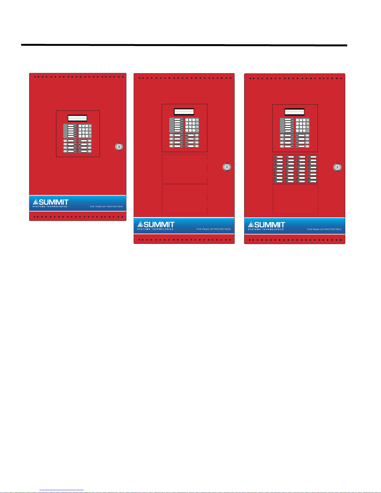
Panel Models
SFC-500 SERIES
Addressable Fire Alarm Control Panel
SYSTEM NORMAL
MAY 21, 2006 02:41PM
AC ON
1 2
X
ABC3DEF
COMMON ALARM
5
4
GHI
7 8
PRS
* 0QZ#
M
JKL6MNO
?
TUV9WXY
SIGNAL
SILENCE
BUZZER
SILENCE
LAMP
TEST
SPARE
COMMON SUPV
COMMON
TROUBLE
CPU FAULT
GROUND
FAULT
SYSTEM
RESET
FIRE
DRILL
ALARM
ACKNOWLEDGE
GENERAL
ALARM
SFC-500 SERIES
Addressable Fire Alarm Control Panel
SYSTEM NORMAL
MAY 21, 2006 02:41PM
AC ON
1 2
X
ABC3DEF
COMMON ALARM
5
4
COMMON SUPV
COMMON
TROUBLE
CPU FAULT
GROUND
FAULT
SYSTEM
RESET
FIRE
DRILL
ALARM
ACKNOWLEDGE
GENERAL
ALARM
ZONE -1
ZONE -1
ZONE -1
ZONE -1
ZONE -1
ZONE -1
ZONE -1
ZONE -1
M
GHI
JKL6MNO
7 8
?
PRS
TUV9WXY
* 0QZ#
SIGNAL
SILENCE
BUZZER
SILENCE
LAMP
TEST
SPARE
ZONE -1
ZONE -1
ZONE -1
ZONE -1
ZONE -1
ZONE -1
ZONE -1
ZONE -1
ZONE -1
ZONE -1
ZONE -1
ZONE -1
ZONE -1
ZONE -1
ZONE -1
ZONE -1
ZONE -1
ZONE -1
ZONE -1
ZONE -1
ZONE -1
ZONE -1
ZONE -1
ZONE -1
All SFC-500 Series Panels have the following features:
• Multi-zone fire alarm control panel with 2 x 20 LCD display.
• Style Y or Style D analog loop(s).
• Four Power Limited Class B (Style Y) indicating circuits (max 1.7 Amps each - 5 Amps total).
• Dedicated common alarm, supervisory, trouble, and auxiliary alarm relays.
• Additional SRAX-532 Display Adders can be added to provide 64 annunciation points per adder.
• An optional SOCA-204 Class A converter module may be used to convert the indicating circuits to Class A (Style Z).
• Additional outputs include connections for a RTI remote trouble indicator, SPR-200 Reverse Polarity Module, an RS485 bus for connection of up to seven SRAM-200LCDs, SSR-212s and SRAM-300 Series annunciators.
• Auxiliary power is available in the form of 24V FWR unfiltered and unsupervised, 24VDC filtered and regulated, and
resettable auxiliary power supply.
4
See the table below for the specifics of each panel.
- SIG1 OUT+- SIG2 OUT+
- SIG1 RET+- SIG 2 RET+
BLK RED
BLK RED
- SIG3 OUT+- SIG4 OUT+
- SIG3 RET+- SIG4 RET+
BLK RED
BLK RED
POLARITY
REVERSAL
ALARM
POLARITY
REVERSAL
SUPV
CITY
TIE
+ | - + | - + | -
JW1
JW2
JW4
SFC-500 Series Installation and Operation Manual
Model # of
points
# of
loops
2 line UDACT Digital
Communicator (y/n)
Door
Color
# of 32 point LED
Displays
Max # of LED
Displays
SFC-500-60-DR 60 1 y red n/a n/a
SFC-500-126-DR 126 1 y red n/a n/a
SFC-500-378-DR 378 3 y red n/a n/a
SFC-551-DR 126 1 y red 0 2
SFC-551-LDR 126 1 y red 1 2
SFC-553-DR 378 3 y red 0 2
SFC-553-LDR 378 3 y red 1 2
Some models may not be available in all markets. Verify with your local distributor.
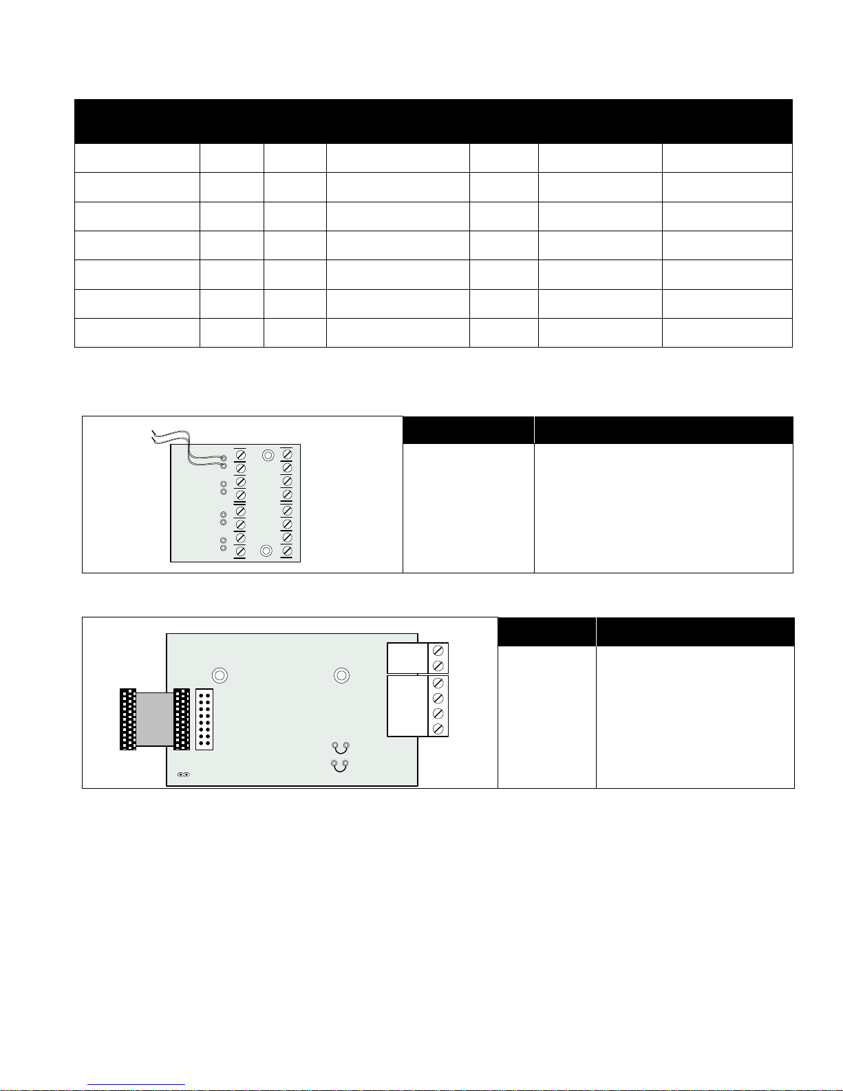
Output Class A converter: four circuits
Model Description
SOCA-204
Output Class A converter module (four
circuits)
Polarity reversal/city tie
Model Description
SPR-200
Polarity Reversal and/or City
Tie Modul e
5
System Components
SYSTEM
RESET
SIGNAL
SILENCE
FIR E
DRILL
BUZZER
SILENCE
LAMP
TEST
1
4
7
*
2
5
8
0
3
6
9
#
ENTER
MEN U
CANCEL
INFO
ABC DEF
GHI JKL MNO
PRS
TUV
WXY
QZ
A.C. ON ALARM S UPV TRBL CPU FAIL
SYSTEM NORMAL
18:01 MON 2010-01-01
SFC-200 SERIES
Remote Annunciat or
A.C.ONCOMMON
TROUBLE
SIGNAL
SILENCED
SIGNAL
SILENCE
SYSTEM
RESET
LAMP
TEST
BUZZER
SILENCE
SRAM-216
Remote Annunciator
Smart Relay Module
Model Description
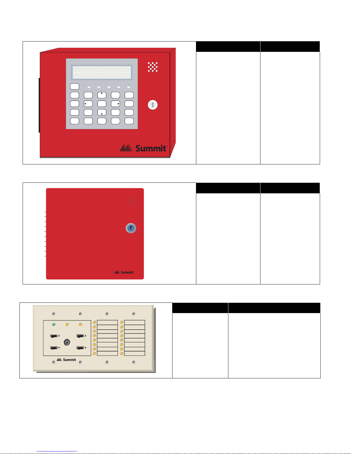
SRAM-200LCDR
Remote Annunciator
Module, LCD
display, red painted
box
SFC-200 SERIES Remote Relay
SRAM-216 Remote Annunciator
Model Description
Smart Relay Module
SSR-212R
(12 relays) with red
enclosure
Model Description
SRAM-216 16 Zone remote annunciator
6

SFC-500 Series Installation and Operation Manual
Panel Components and System Accessories
MODEL NO. DESCRIPTIONS
SALC-252 252 Point Dual Loop Addressable Adder
SRAX-532 32 Zone Internal Display Adder (for SFC-551 and SFC-553 only)
SRAM-208(R) 8 LED Remote Annunciator (red)
SRAM-216(R) 16 LED Remote Annunciator (red)
SRAM-316 / TZ 16 LED Annunciator chassis / TZ has 16 yellow LEDs for trouble indication.
SRAM-332 / TZ
SGD-32 Graphic Annunciator
SGD-048 Graphic Annunciator Adder Driver Board
SRTI-200 Remote Trouble Indicator, Buzzer and LED
SFC-200TRB Trim Ring For Enclosure (Black)
SFC-UNIV-TRB Trim Ring For Larger Enclosure (Black)
SBB-301(R) Enclosure for one annunciator, white. R version is red.
SBB-302(R) Enclosure for two annunciators, white. R version is red.
SBB-303(R) Enclosure for three annunciators, white. R version is red.
SBB-308(R) Enclosure for eight annunciators, white. R version is red.
SBB-312(R) Enclosure for twelve annunciators, white. R version is red.
MP-300 End-of-line resistor plate, 3.9K ohm
BC-160 External Battery Cabinet
Remote Annunciator with 32 bi-colored (red and yellow) LEDs. TZ version has 32 yellow
LEDs for trouble indication.
7

System Components
Analog/Addressable Devices
DESCRIPTION Summit Model
Ionization Smoke Detector (UL Listed) SII-200
Photoelectric Smoke Detector SIP-200
* Multi-sensor (photoelectric with supplemental rate-of-rise heat sensor)
Heat Detector SIH-200
SIM-200
BASES
4 inch Standard Base SIB-4
6 inch E-Z Fit Base SIB-6
6 inch Base with Relay SIB-6R
6 inch Base with Sounder SIB-6S
6 inch Base with Temporal Tone Sounder SIB-6TH
ANCILLARY MODULES
Priority Monitor Module SIM-100P
Mini Priority Monitor Module SIM-101P
Single Relay Output Module (1 Form C Contacts, 2 Gang Mount) 55000-820
Supervised Control Module SIM-100S
SIM-100X (Kit)
Isolator c/w Mounting Base
100XH (Isolator)
100XB (Base)
ADDRESSABLE DUCT DETECTORS
Ionization Duct Smoke Detector (UL Listed) SIDH-200I
Photoelectric Duct Smoke Detector (UL Listed) SIDH-200P
Ionization Duct Smoke Detector with relay (UL Listed) SIDH-200IR
Photoelectric Duct Smoke Detector with relay (UL Listed) SIDH-200PR
ADDRESSABLE PULL STATIONS
Addressable Single Stage Single Action Pull Station SPS-201ID
Addressable Single Stage Dual Action Pull Station SPS-202ID
* Unit employs an integral heat sensor; however it must not be used as a regular heat detector. Refer to the
product data sheet for detailed functionality, operation and application.
Manual configuration for the SIM-200 is NOT PERMITTED. This device must be configured via the AUTO
CONFIG.
8
SFC-500 Series Installation and Operation Manual
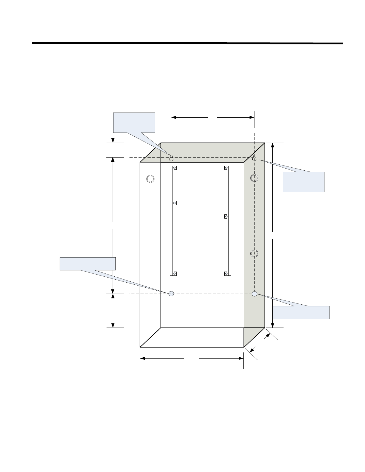
11"
14.5"
1.5"
14.5"
5.4"
4.5"
20"
Mounting
Hole
Moun ting H o le
Mounting
Hole
Mounting H o le
Mechanical Installation
Installing the Enclosure
Install the SFC-500 Series Fire Alarm Panel enclosure as shown below. Mount the enclosure using the four mounting
holes and the screws provided.
Figure 1: Wallbox Dimensions / Mounting the SFC-500 - Surface
9

Mechanical Installation
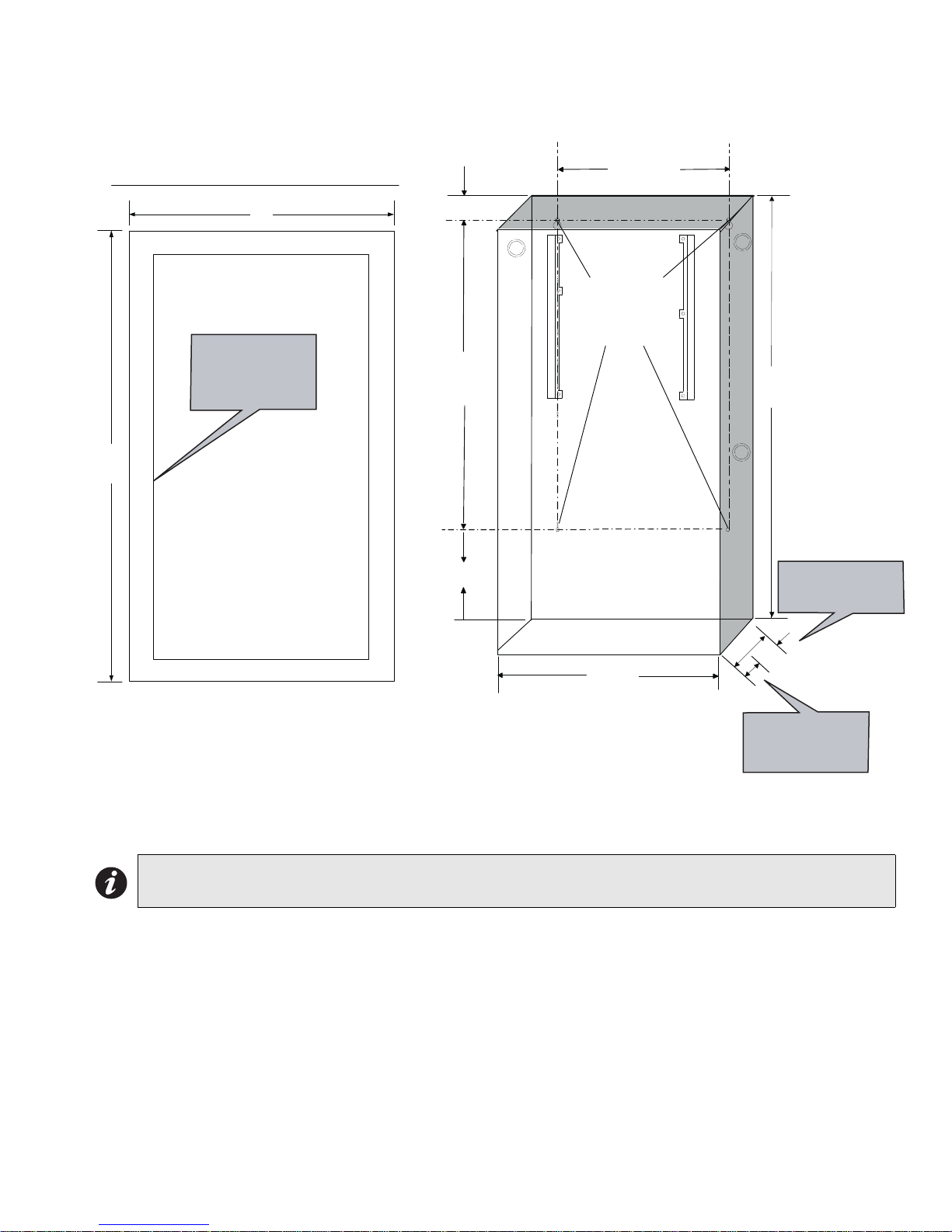
Back box
Trim ring
Wall
Wood stud
Figure 2: Mounting the SFC-500 - Flush
PLACE SFC -200TRB TRIM RING OVER BACKBO X
17"
Adhere trim ring to
wall surface around
SFC-500 backbox
14.5"
11"
1.5"
4 Mounting
Holes fo r
Surface
Mounting
20.0"
22.5"
4"
14.5"
3.5" is the maximum depth
for semi-flush mounting
using the flush trim ring
"
5
.
4
3.5"
1"
1" is the minimum depth
above the wall required
for semi-flush mounting
using the flush trim ring
Figure 3 shows a cross-section of the semi-flush mounted backbox and the trim ring. Make sure to allow a
minimum depth of 1” above the wall surface for proper door opening.
Figure 3: Flush Trim Detail
10
SFC-500 Series Installation and Operation Manual
17"
28.5"
PLACE SFC -U NIV -TRB TRIM RING OVER BACKBO X
14.5"
3.5"
1"
4
.
5
"
11"
26"
1.5"
4"
20.5"
3.5" is the maximum depth
for semi-flush mounting
using the flush trim ring
1" is the minimum depth
above the wall required
for semi-flush mounting
using the flush trim ring
4 Mounting
Holes for
Surface
Mounting
Adhere trim ring to
wall surface around
SFC-551 backbox
Figure 4: Wallbox Dimensions / Mounting the SFC-551/SFC-553 – Surface /Flush
Note: See Figure 3 for Flush Trim Details for mounting the trim ring.
11
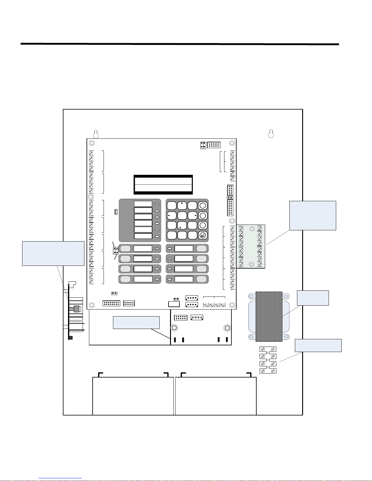
Installing Adder Modules
CLASSA converter
board for indicating
Circuits SOCA-204
(4 circuits)
Reverse polarity and city
tie mo dule SPR-200.
Mounted on hex spacer
with two screws provided.
Transformer
AC wiring terminal
-SIG1 OUT+-SIG2 OUT+
-SIG1RET+-SIG2RET+
BLK
RED
BLK
RED
-SIG3 OUT+-SIG4 OUT+
-SIG3 RET+-SIG4RET+
BLK
RED
BLK
RED
P3
BATTERY
P4
+
-
P1
P2
SEC TX
P6 P5
POWER
SUPPLY
Power supply
board
BATTERY
+-
BATTERY
+-
S-+NC NOCNC NOCNC NOCNC NOC RTRT RTRT
RES CO RES CO
LINE1LINE2
JW7
-+-+
-+-+-+-+
SIG 1SIG 2SIG 3SIG 4
RS-485AUX. RELAY
ALARM
RELAY
SUPERVISORY
RELAY
TROUBLE
RELAY
AUX
SUPPLY
4-WIRE
SUPPLY
COM+COM-TRLTRB
UNFILTERED
FWR 24VDC
RTI
PORT
SYSTEM NORM AL
OCT 21 , 2005 02:41AM
Loop
A
+
+
-
B
JW9
JW1
JW3
JW4
SYSTEM
RESET
FIRE
DRILL
ALARM
ACKNOWLEDGE
GENERAL
ALARM
SIGNAL
SILENCE
BUZZER
SILENCE
LAMP
TEST
SPARE
AC ON
1 2
ABC
3
5 6
7 8 9
* 0 #
4
X
M
?
DEF
GHI JKL MNO
PRS
TUV
WXY
QZ
COMMON ALARM
COMMON SUPV
COMMON TROUBLE
CPU FAULT
GROUND FAULT
JW2
JW6
JW5
For PC programming use UIMA
Interface module not UL-864 or
ULC-527 listed. Please refer to
Document LT-929 for details
RS-232C PORT
TO POWER SUPPLY
P12
P3
P2
P8
P4
SPR-20 0 is m o un ted
here for SFC-551
Installing Adder Modules
The SFC-500 Fire Alarm panels come pre-assembled with all components and boards except for Adder Modules.
Module installation locations are shown in Figure 5. Refer to Figure 6 on the next page for Jumper or DIP Switch
settings and see Wiring Tables and Information for wiring specifications.
Figure 5: Installation of Adder Modules
12
 Loading...