

Page 1

Integrated Refrigeration Installation Guide
Page 2

INTEGRATED REFRIGERATION
Contents
3 Integrated Refrigeration
4 Opening Dimensions
5 Electrical
5 Plumbing
6 Preparation
6 Anti-Tip Bracket
8 Placement
8 Alignment
9 Water Line
10 Custom Panels
12 Panel Installation
14 Completion
Features and specications are subject to change at any
time without notice. Visit subzero.com/specs for the most
up-to-date information.
Important Note
To ensure this product is installed and operated as safely
and efciently as possible, take note of the following types
of highlighted information throughout this guide:
IMPORTANT NOTE highlights information that is especially
important.
CAUTION indicates a situation where minor injury or product
damage may occur if instructions are not followed.
WARNING states a hazard that may cause serious injury or
death if precautions are not followed.
IMPORTANT NOTE: Throughout this guide, dimensions in
parentheses are millimeters unless otherwise specied.
IMPORTANT NOTE: Save these instructions for the local
electrical inspector.
Page 3
INTEGRATED REFRIGERATION
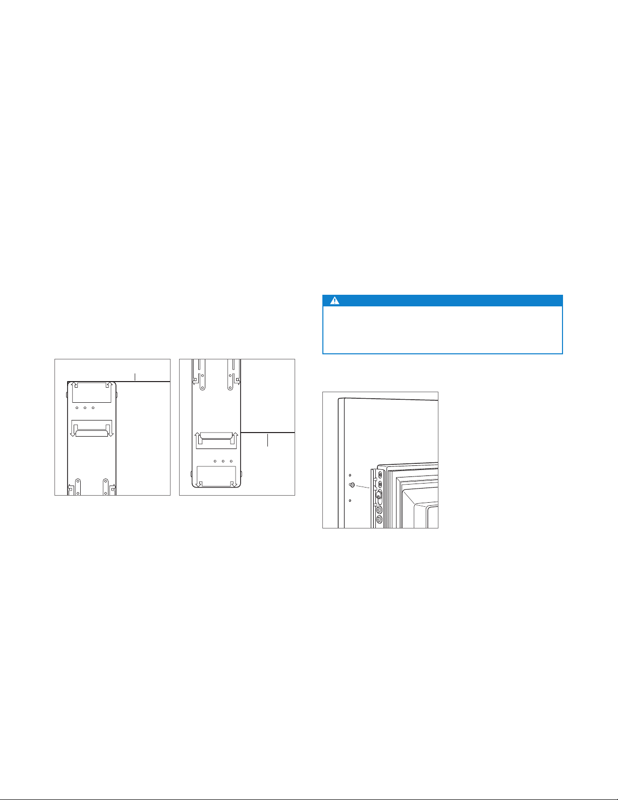
Product Information
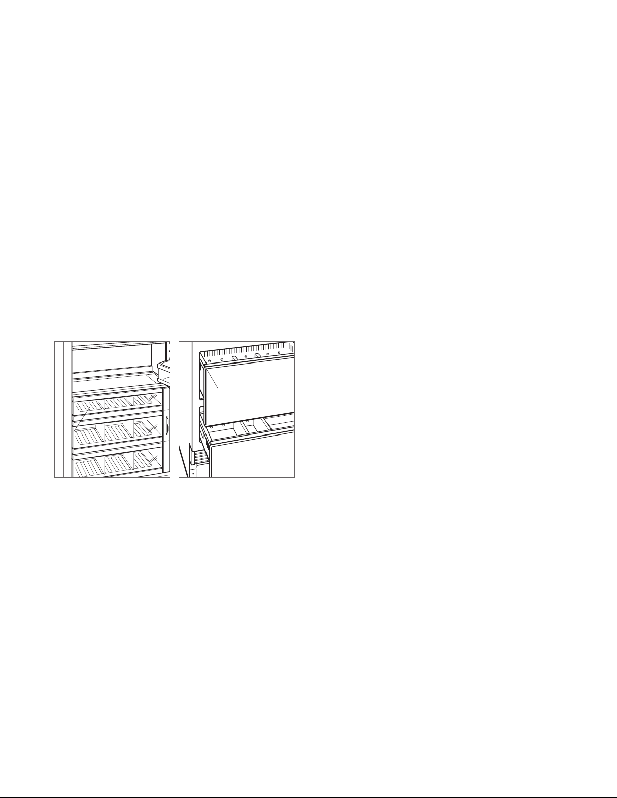
Important product information including the model and
serial number are listed on the product rating plate. For
column models, the rating plate is located inside the middle
drawer near the drawer guide opposite the hinge. For tall
and drawer models, the rating plate is located inside the
cabinet, to the left of the upper drawer. Refer to the illustrations below.
If service is necessary, contact Sub-Zero factory certied
service with the model and serial number. For the name
of the nearest Sub-Zero factory certied service or for
questions regarding the installation, visit the contact & support section of our website, subzero.com or call Sub-Zero
customer care at 800-222-7820.
RATING
PLATE
RATING
PLATE
Tools and Materials
• Screwdrivers—standard, Phillips and Torx.
• Power drill.
• Drill bits (masonry bits required for concrete installation).
• Standard socket and wrench set.
• 2' and 4' levels.
• Tubing cutter.
(.9 m) of
• 3'
PEX tubing.
• Saddle valve.
• Material to protect home, ooring and cabinetry during
installation.
1
/4" OD copper, braided stainless steel or
Column models.
Tall and drawer models.
subzero.com | 3
Page 4
SITE PREPARATION
NOTE:
SIDE
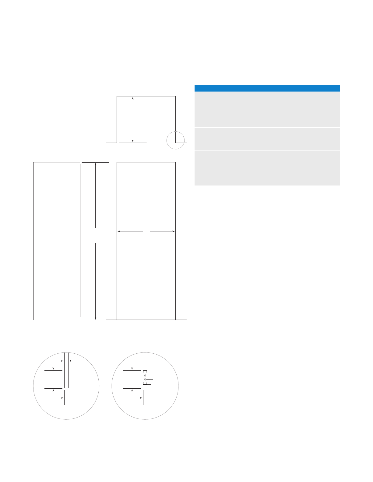
Opening Dimensions
INTEGRATED MODELS
H
OPENING
HEIGHT
(635)
25"
OPENING
DEPTH
TOP VIEW
OPENING WIDTH
OPENING DIMENSIONS
COLUMN W H
IC-18FI 18" (457) 84" (2134)
IC-24R, IC-24FI 24" (610) 84" (2134)
IC-30R(ID), IC-30FI 30" (762) 84" (2134)
IC-36R(ID) 36" (914) 84" (2134)
TALL W H
IT-30R(ID), IT-30FI, IT-30CI(ID) 30" (762) 84" (2134)
IT-36R(ID), IT-36CI(ID) 36" (914) 84" (2134)
DRAWER W H
ID-24R, ID-24F(I) 24" (610) 341/2" (876)
ID-27R 27" (686) 341/2" (876)
ID-30R(P), ID-30F(I), ID-30C(I) 30" (762) 341/2" (876)
ID-36R(P), ID-36C(I) 36" (914) 341/2" (876)
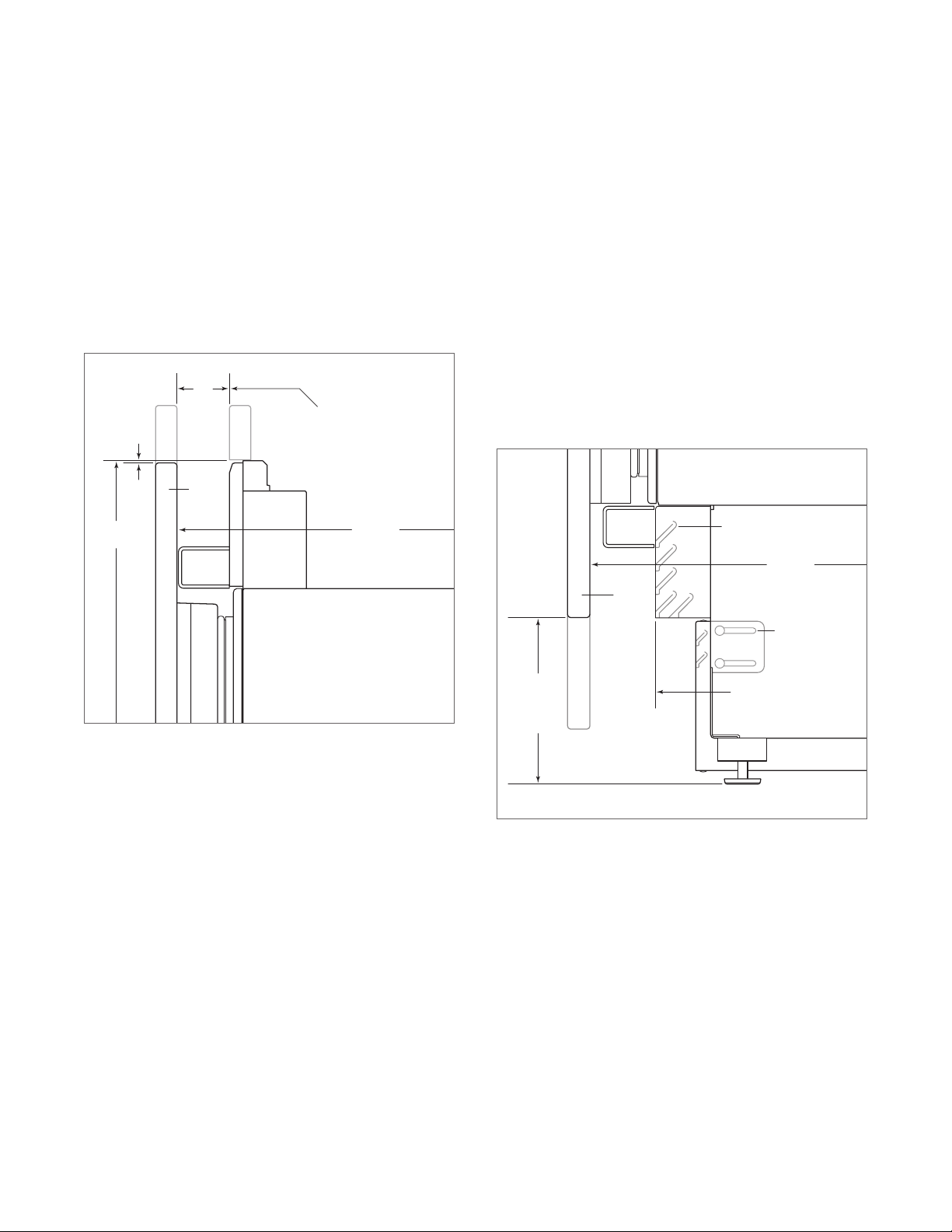
The depth of each integrated model is 24" (610). Allow for
panel thickness when planning the nished opening depth.
1
A minimum 3
/2" (89) nished return is required on all sides
of the opening. Framed cabinets will require additional
W
nished ller material behind the face frame for a proper
installation. Refer to the illustration.
DUAL INSTALLATION
VIEW
31/2" (89) finished returns will be visible and should be finished to match cabinetry.
3
/4"
(19)
31/2" (89)
FINISHED
RETURN
W W
FRAMELESS CABINETRY
TYPICAL
FRONT VIEW
31/2" (89)
FINISHED
RETURN
FRAMED CABINETRY
FILLER
When installing two units side by side in a dual installation, the opening width is the width of the two units added
together. A dual installation kit will be required for this installation. If a dual installation kit is not specied, a minimum
(51) ller strip is required between units.
2"
Dual installation kits are available through an authorized
Sub-Zero dealer. For local dealer information, visit the nd a
showroom section of our website, subzero.com. For questions regarding the installation, call Sub-Zero customer care
at 800-222-7820.
4 | Sub-Zero Customer Care 800.222.7820
Page 5
SITE PREPARATION
Electrical
Installation must comply with all applicable electrical codes.
The electrical supply must be located within the shaded
area shown in the illustration and chart below. A separate
circuit, servicing only this appliance is required. A ground
fault circuit interrupter (GFCI) is not recommended and may
cause interruption of operation.
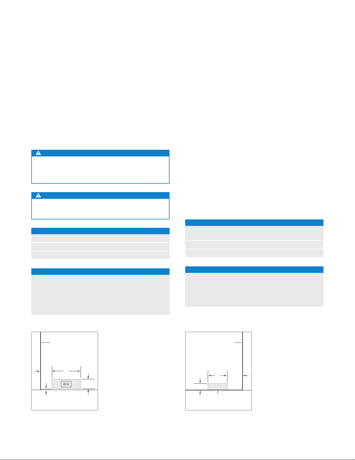
The electrical outlet must be positioned with the grounding
prong to the right of the thinner blades.
CAUTION
The outlet must be checked by a qualied electrician to
be sure that it is wired with the correct polarity. Verify
that the outlet is properly grounded.
WARNING
Do not use an extension cord, two-prong adapter or
remove the power cord ground prong.
ELECTRICAL REQUIREMENTS
Electrical Supply 115 VAC, 60 Hz
Service 15 amp
Receptacle 3-prong grounding-type
Plumbing
Installation must comply with all applicable plumbing codes.
The water supply line should be located within the shaded
area shown in the illustration below. The water supply line
should be connected to the house supply with an easily
accessible shut-off valve. Do not use self-piercing valves.
The water supply line must be ush to the oor and not
interfere with installation of the anti-tip bracket.
Column and tall models with an ice maker or water dispenser feature a water ltration system. An in-line lter is
required for drawer models with an ice maker when water
conditions have a high sediment content.
A reverse osmosis system can be used provided there is
constant water pressure of 35–120 psi
to the unit at all times. In this application, the water ltration system must be bypassed. Refer to water lter bypass
on page 15. A copper line is not recommended for this
application.
PLUMBING REQUIREMENTS
Water Supply Line
Water Pressure 35–120 psi
Excess Water Line for Connection 36" (914)
(2.4–8.3 bar) supplied
1
/4" OD copper, braided
stainless steel or PEX tubing
(2.4–8.3 bar)
ELECTRICAL SUPPLY LOCATION
WIDTH A
18" Models 6" (152)
24" Models 91/2" (241)
27" Models 11" (279)
30" Models 121/2" (318)
36" Models 151/2" (394)
LEFT SIDE
OF OPENING
41/2"
(114)
1
/4" (6)1/4" (6)
Electrical supply location.
A
FLOOR
41/4"
(108)
WATER SUPPLY LOCATION
WIDTH A
18" Models 3" (76)
24" Models 51/2" (140)
30" Models 6" (152)
36" Models 9" (229)
RIGHT SIDE
OF OPENING
6" (152)
A
3" (76)
1
AREA EXTENDS
FORWARD ON FLOOR
Water supply location.
/2" (13)
subzero.com | 5
Page 6
SITE PREPARATION
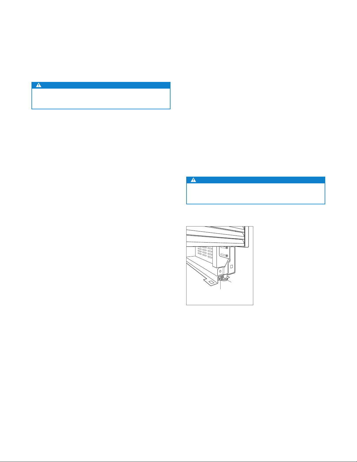
Preparation
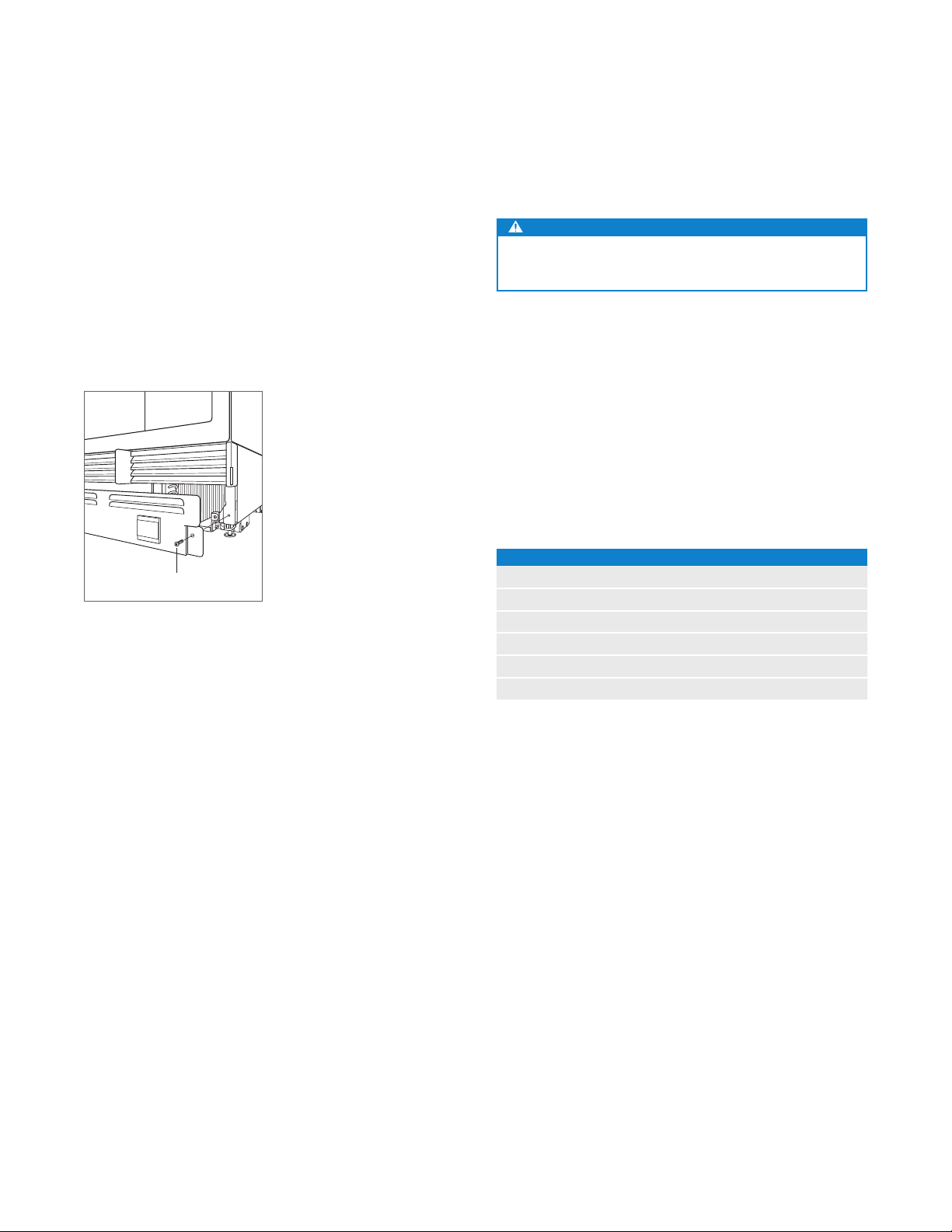
Uncrate the unit and inspect for damage. Remove the wood
base and discard shipping bolts and brackets. Remove and
recycle packing materials. Do not discard the kickplate, antitip bracket and hardware.
Remove the kickplate by extracting the two mounting
screws. Refer to the illustration below.
SCREW
Kickplate removal.
Anti-Tip Bracket
WARNING
To prevent the unit from tipping forward, the anti-tip
bracket must be installed.
The back of the anti-tip bracket must be installed 24" (610)
from the front of the unit (without panels).
Use all anti-tip bracket hardware as instructed for wood or
concrete oors.
IMPORTANT NOTE: For wood or concrete oor applications,
if the #12 screws do not hit a wall stud or wall plate, use the
#8 screws and #12 washers with the wall anchors.
IMPORTANT NOTE: In some installations the subooring or
nished oor may necessitate angling the screws used to
fasten the anti-tip bracket to the back wall.
ANTI-TIP HARDWARE
1 Anti-tip bracket
1
12 #12 x 2
4
12 #12 at washers
4 #8–18 x 1
4 Nylon Zip-it
/2" pan head screws
3
/8"–16 x 33/4" wedge anchors
1
/4" truss head screws
®
wall anchors
6 | Sub-Zero Customer Care 800.222.7820
Page 7
SITE PREPARATION
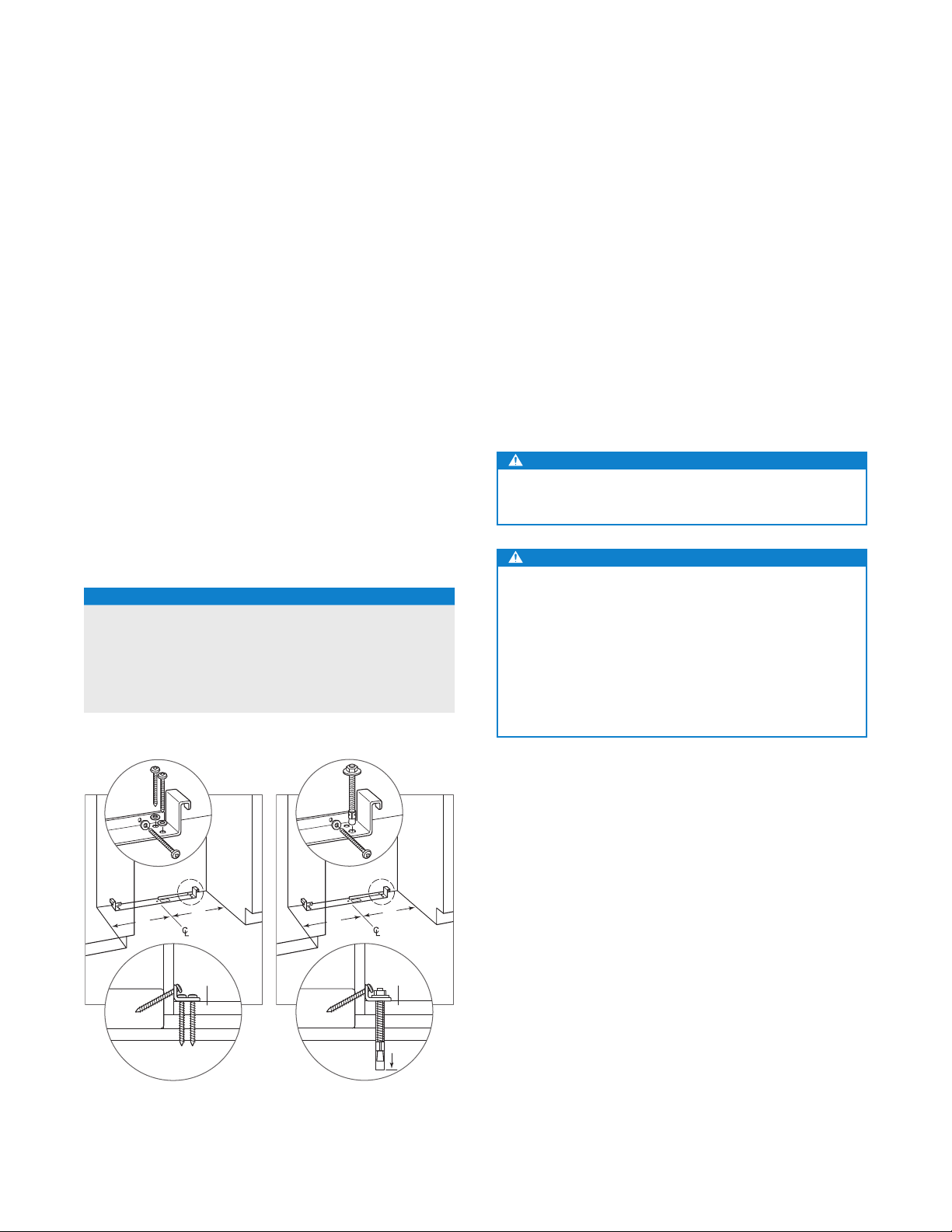
Anti-Tip Bracket
WOOD FLOOR APPLICATION
After properly locating the anti-tip bracket in the opening,
3
drill pilot holes
/16" (5) diameter maximum in the wall studs
or wall plate. Use the #12 screws and washers to secure the
brackets. Verify the screws penetrate through the ooring
3
material and into wall studs or wall plate a minimum of
(19)
. Refer to the illustration and chart below.
/4"
CONCRETE FLOOR APPLICATION
After properly locating the anti-tip bracket in the opening,
3
drill pilot holes
or wall plate. Drill
a minimum of 1
washers to secure the brackets to the wall, and use the
/16" (5) diameter maximum in the wall studs
3
/8" (10) diameter holes into the concrete
1
/2" (38) deep. Use the #12 screws and
3
/8"
wedge anchors to secure the brackets to the oor. Verify the
3
screws penetrate wall studs or wall plate a minimum of
(19)
. Refer to the illustration and chart below.
ANTI-TIP BRACKET PLACEMENT
WIDTH A
18" Models 9" (229)
24" Models 12" (305)
27" Models 131/2" (343)
30" Models 15" (381)
36" Models 18" (457)
/4"
CONCRETE WEDGE ANCHOR INSTALLATION:
1 Drill a
3
/8" (10) diameter hole any depth exceeding the
minimum embedment. Clean the hole or drill additional
depth to accommodate drill nes.
2 Assemble the washer and nut ush with the end of
anchor to protect threads. Drive the anchor through the
material to be fastened until the washer is ush with the
surface material.
3 Expand the anchor by tightening the nut 3–5 turns past
hand-tight position or to 25 foot-pounds of torque.
WARNING
Verify there are no electrical wires or plumbing in the
area which the screws could penetrate.
CAUTION
Always wear safety glasses and use other necessary protective devices or apparel when installing or
working with anchors.
Anchors are not recommended for use in lightweight
masonry material such as block or brick, or for use in
new concrete which has not had sufcient time to cure.
The use of core drills is not recommended to drill holes
for the anchors.
WALL PLATE
SUBFLOORING
Wood oor.
A
FINISHED
FLOORING
WOOD FLOOR
A
A
WALL PLATE
SUBFLOORING
CONCRETE
FLOOR
A
FINISHED
FLOORING
11/2"(38)
min
Concrete oor.
subzero.com | 7
Page 8
INSTALLATION
Placement
CAUTION
Before moving the unit into position, secure the door/
drawers closed and protect any nished ooring.
Use an appliance dolly to move the unit near the opening.
The front leveling legs are extended below the front rollers to
improve stability during placement. Once the unit is placed
in front of the opening, completely retract the front leveling
legs to allow the unit to be rolled into position. Front and
rear leveling legs can be adjusted from the front once the
unit is positioned.
If the unit has been on its back or side, it must stand upright
for a minimum of 24 hours before connecting power.
Plug the power cord into the grounded outlet and roll the
unit into position. Verify the anti-tip bracket is properly
engaged.
Alignment
LEVELING
Once the unit is in position, height adjustment can be made
from the front. Using a Phillips drive, turn clockwise to raise
the unit or counterclockwise to lower. Use the lowest torque
setting when using a power drill. Do not turn the leveling
legs by hand. Refer to the illustration below.
When the unit is properly leveled, door/drawer adjustments
are less likely to be necessary.
IMPORTANT NOTE: Level the unit to the oor, not sur-
rounding cabinetry. This could affect the operation of the
unit, such as door closing.
WARNING
To reduce the possibility of the unit tipping forward,
the front leveling legs must be in contact with the oor.
8 | Sub-Zero Customer Care 800.222.7820
Leveling.
REAR
ADJUSTMENT
FRONT
ADJUSTMENT
Page 9
INSTALLATION
Alignment
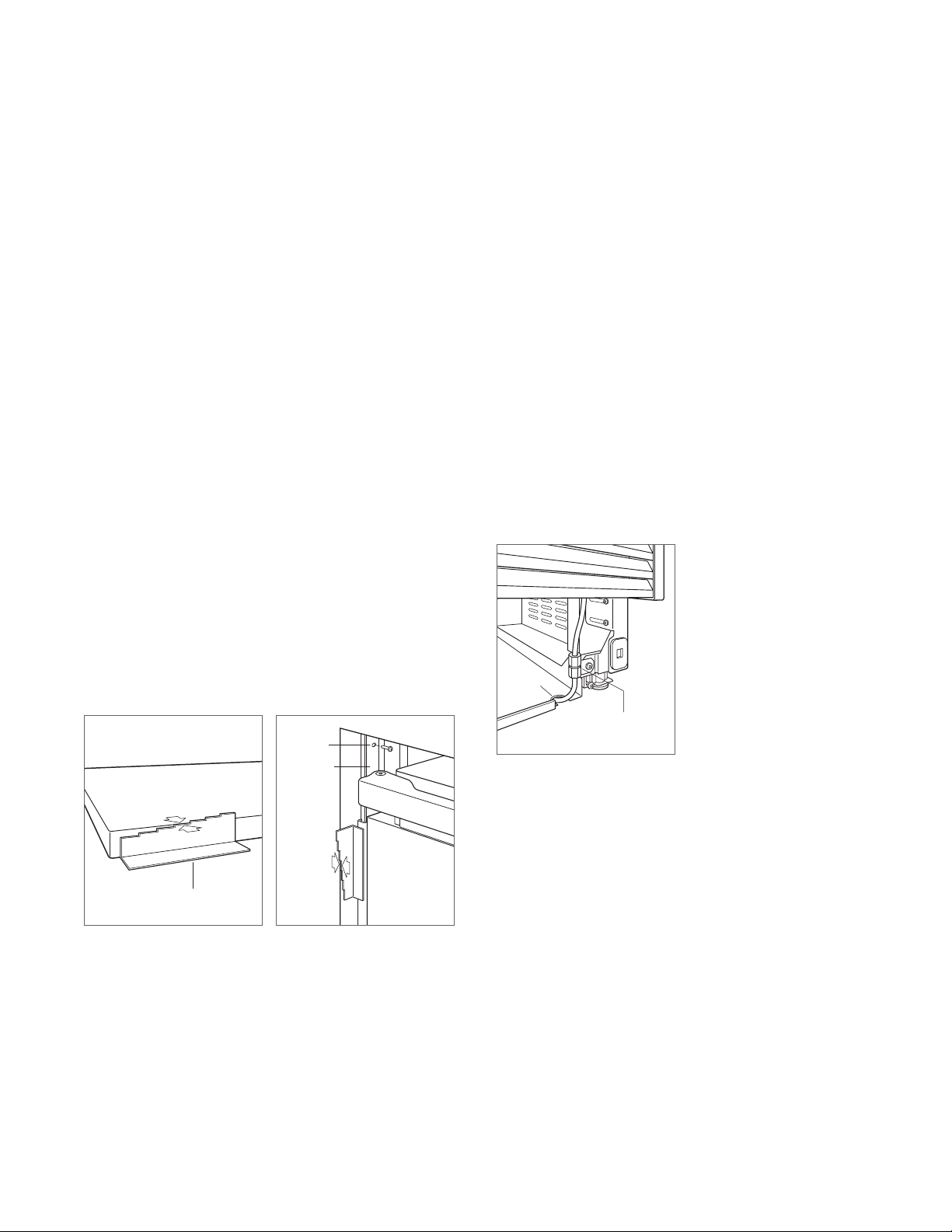
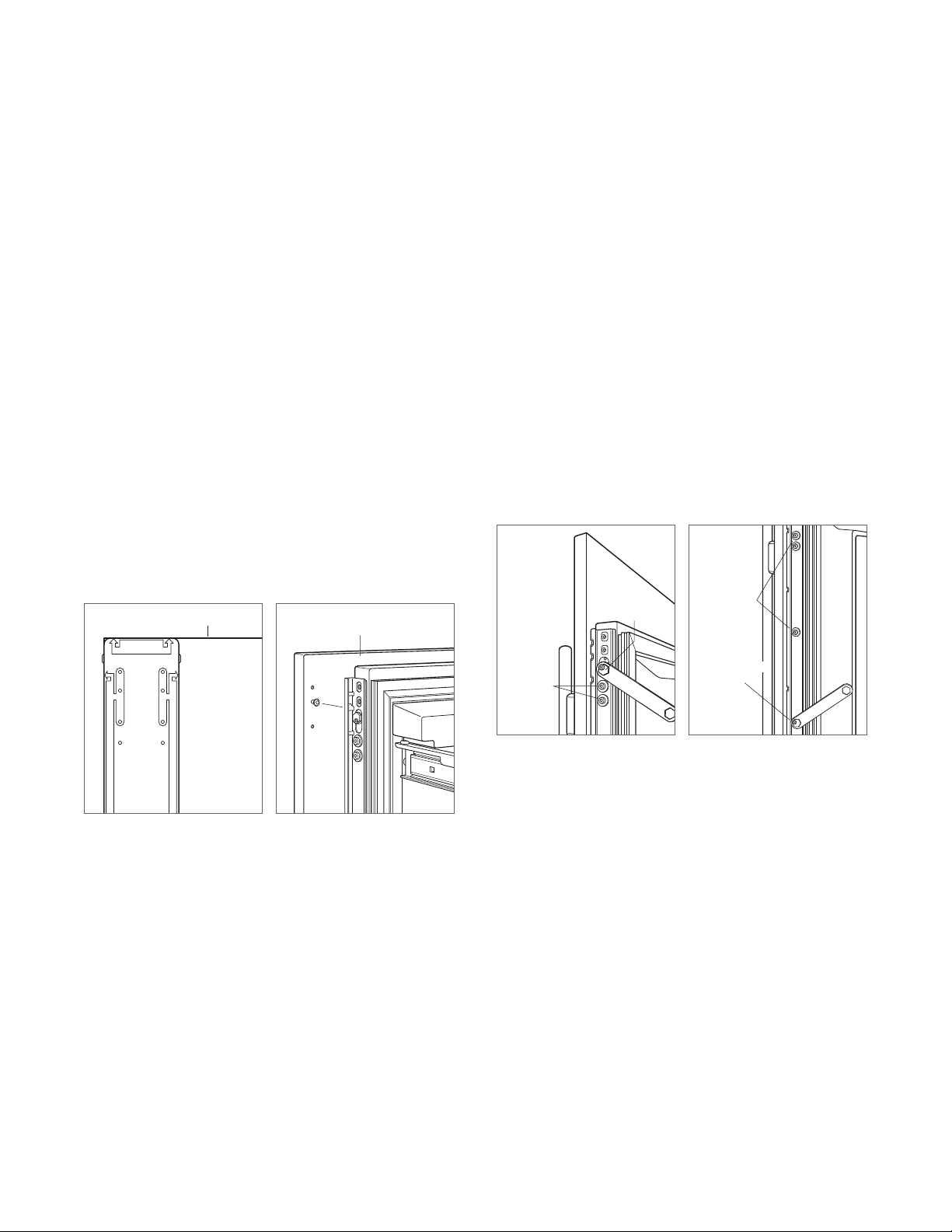
DEPTH ADJUSTMENT
Adjust the depth of the unit to t ush with surrounding
cabinetry. Follow these steps for a precision t:
1 Place decorative panel on a protected work surface.
Place the panel thickness gauge next to the panel to
determine which notch corresponds with the panel thickness. Refer to the illustration below. Once the proper
notch has been determined, mark that notch with a
marker.
2 With the door closed, position the top of the unit using
the panel thickness gauge. Refer to the illustration
below. Insert a #8 x
hinge, then insert a #8 x
handle side of the unit. For narrower units, the door may
need to be opened to access the handle side screw
location. Repeat the process to align the bottom.
ANCHORING
Once the top and bottom are aligned, verify doors and
drawers open properly, then install remaining screws in each
side trim.
1
/2" stainless steel screw above the
1
/2" pan head screw on the
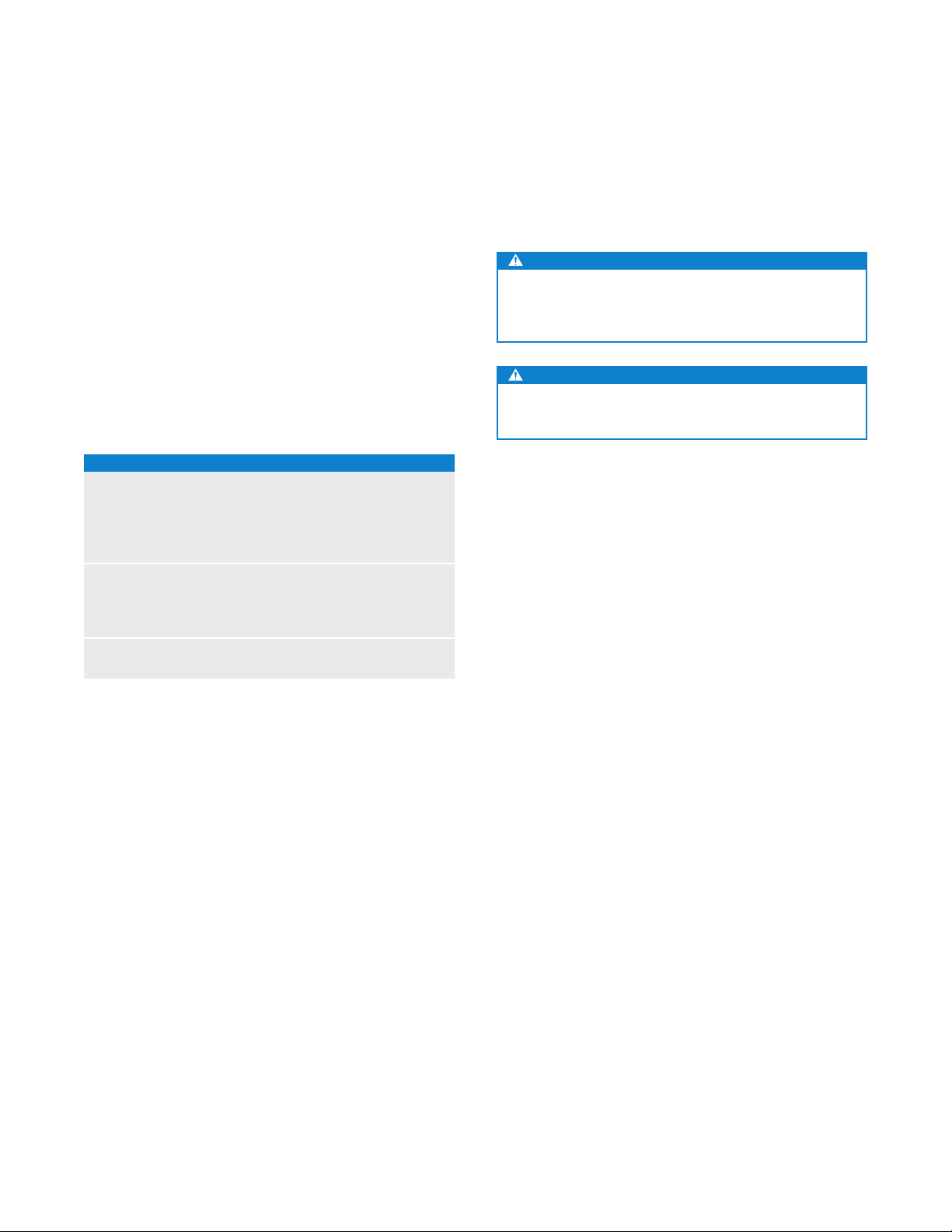
Water Line
Purge the water line prior to nal connection to the unit. This
will remove any debris that may be present in the tubing
from installing the new water line. Connect the plastic tubing
from the unit to the house water supply line with the tting
connection kit provided. Check all water line ttings for
leaks.
Locate the water line in the notch as shown in the illustration
below.
IMPORTANT NOTE: If a reverse osmosis system used, it is
recommended that the water ltration system be bypassed
by removing the lter.
IMPORTANT NOTE: Water lines can not be exposed to
freezing temperatures.
NOTCH
PANEL THICKNESS
Panel thickness.
GAUGE
SCREW
SIDE TRIM
CABINETRY
FACE
FRAME
Unit depth.
FRONT OF
UNIT
Water line.
WATER LINE
CONNECTION
subzero.com | 9
Page 10
PANEL INSTALLATION
Custom Panels
For integrated models, custom door panels and handle
hardware must be installed. Stainless steel panels are
available through an authorized Sub-Zero dealer. For local
dealer information, visit the nd a showroom section of our
website, subzero.com.
The thickness of the custom panel can vary. A minimum
5
/8" (16) thick panel is required, but the thickness can be
increased provided it does not exceed the maximum panel
weight indicated in the chart below. The depth of each
integrated model is 24"
(610). Allow for panel thickness when
planning the nished opening depth.
PANEL REQUIREMENTS
PANEL WEIGHT MAX
18" Column 45 lb (20 kg)
24" Column 60 lb (27 kg)
30" Column 75 lb (34 kg)
36" Column 75 lb (34 kg)
PANEL WEIGHT MAX
30" Tall (door) 50 lb (22 kg)
36" Tall (door) 60 lb (27 kg)
Drawer 15 lb (7 kg)
PANEL THICKNESS MIN
All Panels
5
/8" (16)
Reveals between panels can vary, 1/8" (3) reveals are typical.
CAUTION
When installing a panel thicker than 1" (25), the 90° stop
may be required to prevent damage to the unit and
adjacent cabinetry.
CAUTION
As reveals between cabinetry and the unit decrease,
severe nger pinching can occur while door is closing.
Finish all sides of custom panels. They will be visible when
the door/drawer is open.
D-style handles are recommended. Door handles must be
located near the edge of the panel opposite the hinge and
should be centered top to bottom. Drawer handles must
be located near the top edge of each panel. Stainless steel
tubular and pro handles are avail able through an authorized
Sub-Zero dealer. For local dealer information, visit the nd a
showroom section of our website, subzero.com.
10 | Sub-Zero Customer Care 800.222.7820
Page 11
PANEL INSTALLATION
Custom Panels
DOOR PANEL HEIGHT
The height of the custom door panel can extend beyond the
typical panel height, provided it does not exceed the weight
limit. Refer to the illustration below.
13/4"
(45)
A DECORATIVE VALANCE
1
/8" (3)
DOOR
PANEL
84"
(2134)
HINGE
Upper valance (column and tall models)—side view.
CANNOT EXTEND
BEYOND THIS PLANE
24" (610)
TO BACK OF UNIT
TOE KICK CLEARANCE
The height of the toe kick area can extend beyond the
typical toe kick height, provided it does not exceed the
dimensions in the illustration below. Toe kick heights from
(51) to 3
2"
7
/8" (98) require a reduced toe kick accessory
available through an authorized Sub-Zero dealer. For local
dealer information, visit the nd a showroom section of our
website, subzero.com. For questions regarding the installation, call Sub-Zero customer care at 800-222-7820.
VENTED
LOUVERS
24" (610)
TO BACK OF UNIT
11/8" (29)
MAX
TOE KICK
ADJUSTMENT
A DECORATIVE TOE KICK
CANNOT EXTEND
BEYOND THIS PLANE
2" (51)*
TO
6" (152)
FROM
FLOOR
HINGE
DOOR
PANEL
*2" (51) to 37/8" (98) requires sales accessory.
Toe kick—side view.
subzero.com | 11
Page 12
PANEL INSTALLATION
EDGE OF DOOR PANEL
EDGE OF DOOR PANEL
Panel Installation
DOOR PANEL INSTALLATION
Typical panel dimensions are based on an 84" (2134) nished
1
height with
/8" (3) reveals. Template placement must be
adjusted for panels exceeding typical dimensions.
For tall models, the door panel should be installed rst,
followed by the upper then lower drawer panel.
Place the panel face down on a protected work surface.
Position the template ush with the top and sides of the
panel. Verify the correct side of the template is being used,
then mark and drill holes. Refer to the illustration below.
For tall models, align the notch in the template with the
bottom of the door panel, then mark and drill holes. Refer to
the illustration below.
TOP OF DOOR PANEL
TOP OF
DOOR PANEL
84" APPLICATION
83 7/8" ACTUAL
USE TABS FOR HINGE
SIDE PANEL EDGE ON
DUAL INSTALLATION
DOOR PANEL
BOTTOM OF
BOTTOM OF
DOOR PANEL
TOP OF
DOOR PANEL
83 7/8" ACTUAL
84" APPLICATION
DUAL INSTALLATION
SIDE PANEL EDGE ON
USE TABS FOR HINGE
BOTTOM OF
DOOR PANEL
1
Use the T-20 torx drive provided to partially insert a #8 x
/2"
screw into the second hole from the top on each side of the
3
panel. The screws should be approximately
/16" (4) proud
of the panel and will support the weight of the panel during
installation.
Align the support screws on the back of the panel with the
slotted holes on both door mounting brackets. Opening the
door slightly may help with alignment. Once the panel is
1
supported by the screws, partially insert a #8 x
/2" screw
into the second hole from the bottom on each side of the
panel, but do not tighten.
CAUTION
As the reveal between cabinets and the unit decreases,
the potential exists for severe nger pinching if ngers
are placed in the opening when the door is closing.
BACK OF
DOOR PANEL
Door panel template—top.
Door panel template—bottom
(tall models only).
Door panel mounting.
12 | Sub-Zero Customer Care 800.222.7820
Page 13
PANEL INSTALLATION
LEFT EDGE OF DRAWER PANEL
Panel Installation
DRAWER PANEL INSTALLATION
Place the panel face down on a protected work surface.
Position the template ush with the top and sides of the
panel. Verify the correct side of the template is being used,
then mark and drill holes. Refer to the illustration below.
1
Use the T-20 torx drive provided, to partially insert a #8 x
/2"
screw into the second hole from the top on each side of the
3
panel. The screws should be approximately
/16" (4) proud
of the panel and will support the weight of the panel during
installation.
Align the support screws on the back of the panel with the
slotted holes on both drawer mounting brackets. Refer to
the illustration below. Opening the drawer slightly may help
with alignment. Once the panel is supported by the screws,
1
partially insert a #8 x
/2" screw into the second hole from
the bottom on each side of the panel, but do not tighten.
TOP OF DRAWER PANEL
TOP OF
DRAWER PANEL
TOP HOLES
FOR UPPER
AND LOWER
DRAWERS
BACK OF
DRAWER PANEL
PANEL ADJUSTMENT
Close the door and/or drawers, now adjustments can be
made to align panels and reveals.
For side-to-side adjustment, move panels side to side, then
install and tighten all mounting screws.
For up-and-down and in-and-out adjustments, slightly
loosen the bracket screws. Depending on the level of
adjustment required, it may be helpful to loosen all of the
bracket screws which will allow for maximum adjustment.
Once the bracket screws are loosened, rotate the cams
to make adjustments. After adjustments have been made,
tighten all bracket screws. Refer to the illustrations below.
BRACKET
SCREWS
UP-AND-DOWN
CAM
BRACKET
SCREWS
IN-AND-OUT
CAM
WER PANEL
Drawer panel template—top. Drawer panel mounting.
In-and-out adjustment.
Up-and-down adjustment.
subzero.com | 13
Page 14
INSTALLATION
Completion
DOOR TRIM INSTALLATION
After panels have been adjusted, install the decorative side
trim to the door/drawers. To install, start at the top and
align the trim with the front and rear anges on the bracket,
then snap into place by pushing the trim toward the back
of the panel. Once the top is secure, continue the installation downward until the remaining trim is completely secure.
Refer to the illustrations below.
DOOR TRIM
FRONT
FLANGE
REAR
FLANGE
Door trim.
Bracket anges.
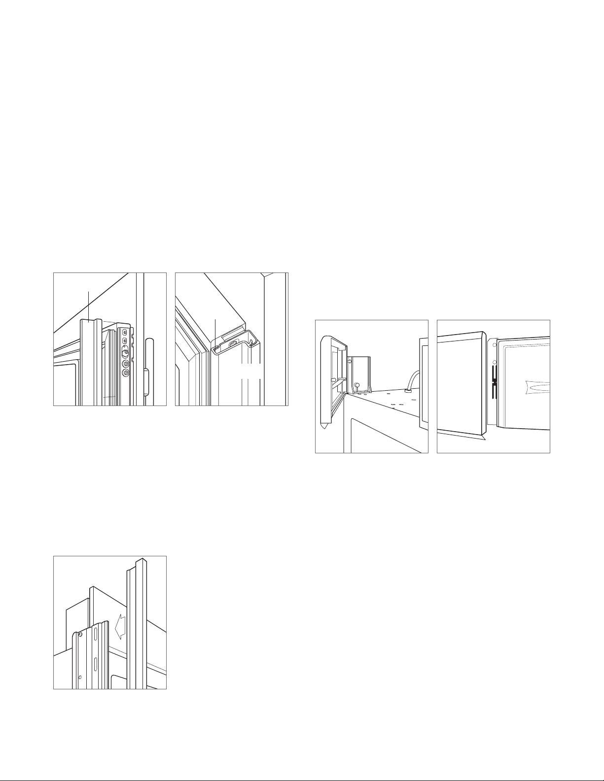
TOP TRIM INSTALLATION
Identify the top trim strips by the notch on one end at the
bottom; this trim strip ts on the hinge side of the unit.
Insert the outer end of each trim strip behind the vertical
side trim. Engage the snap in the plastic side bracket and
slide the panel as far to the outside as possible. Refer to the
illustration below.
Rotate the inner end of each panel into the side ange of
the center shroud, next to the water lter access door. Press
on the trim strip to snap into place. Refer to the illustration
below.
SIDE TRIM INSTALLATION
Install the decorative trim strip to the handle side of tall
and column models. The side trim snaps over the bracket
attached to the handle side of the unit. Refer to the illustration below.
Side trim.
Inner top trim.
Outer top trim.
14 | Sub-Zero Customer Care 800.222.7820
Page 15

INSTALLATION
Completion
KICKPLATE INSTALLATION
Position the kickplate and install using the two mounting
screws. Refer to the illustration below. Kickplate must
be removable for service. The oor cannot interfere with
removal.
A maximum 6"
(152) decorative kickplate can be attached
to the factory-installed kickplate. The two rows of vented
louvers can be covered if door panel is a minimum 4"
(102)
from nished oor.
To install a decorative kickplate, remove paper backing from
the magnets and attach decorative kickplate to magnets.
Magnets may also be tacked into position to increase adhesion. Magnets will allow decorative kickplate to be removed,
if necessary.
Turn power on by touching ‘power’ on the control panel.
90° DOOR STOP
A 105° door stop is built into the hinges of tall and column
units. To limit the door to 90°, open the door slightly less
than 90°, then use a standard screwdriver blade to remove
the existing clips from each hinge. Locate the 90° clips from
inside the plastic bag containing product literature, then
insert the 90° clips onto each hinge. Refer to the illustration
below.
WATER FILTER BYPASS
If the water ltration system will not be utilized, it can be
placed in water lter bypass mode by removing the water
lter. Follow these steps to remove the water lter:
1 Pull out on the bottom edge of the access door and tilt
upward.
2 To remove the lter, rotate counterclockwise one-quarter
turn, then pull out. Refer to the illustration below.
WARNING
Follow all city and state laws when storing, recycling or
discarding unused refrigerators and freezers.
ACCESS DOOR
WATER FILTER
Water lter removal.
CLIP
SCREWMAGNET
Kickplate installation.
Sub-Zero, Sub-Zero & Design, Dual Refrigeration, The Living Kitchen, Great American Kitchens The Fine Art of Kitchen Design, and Ingredients are registered trademarks and service
marks of Sub-Zero, Inc. Wolf, Wolf & Design, Wolf Gourmet, W & Design and the color red as applied to knobs are registered trademarks and service marks of Wolf Appliance, Inc.
All other trademarks or registered trademarks are property of their respective owners in the United States and other countries.
90° door stop.
subzero.com | 15
Page 16

REFRIGERACIÓN INTEGRADA
Contenido
3 Refrigeración integrada
4 Dimensiones de abertura
5 Instalación eléctrica
5 Plomería
6 Preparación
6 Soporte antivuelco
8 Colocación
8 Alineación
9 Línea de agua
10 Paneles personalizados
12 Instalación de los paneles
14 Finalización
Aviso importante
Para garantizar que este producto sea instalado y operado
de la forma más segura y eciente posible, tome nota de los
siguientes tipos de información resaltada en esta guía:
AVISO IMPORTANTE resalta la información que es especial-
mente importante.
PRECAUCIÓN indica una situación en la que se pueden
sufrir heridas leves o provocar daños al producto si no se
siguen las instrucciones.
ADVERTENCIA indica peligro de que se produzcan heridas
graves o incluso la muerte si no se siguen las precauciones.
AVISO IMPORTANTE: En toda esta guía, las dimensiones
entre paréntesis son milímetros, a menos que se especique
lo contrario.
2 | Atención al cliente de Sub-Zero 800.222.7820
Page 17

REFRIGERACIÓN INTEGRADA
Información del producto
La información importante del producto, incluido el modelo
y número de serie de la unidad, se encuentran en la placa
de datos del producto. Para los modelos de columna, la
placa de datos se encuentra dentro del cajón medio del
refrigerador, cerca de la guía de cajón opuesta a la bisagra.
Para los modelos altos y los modelos con cajones, la placa
de datos se encuentra dentro del gabinete, a la izquierda
del cajón superior del refrigerador. Consulte las siguientes
ilustraciones.
Si necesita servicio, póngase en contacto con el centro
de servicio autorizado de Sub-Zero y tenga a la mano el
modelo y número de serie de la unidad. Para obtener los
datos del centro de servicio autorizado de Sub-Zero más
cercano o si tiene preguntas acerca de la instalación, visite
la sección de contacto y soporte técnico en nuestra página
de Internet, subzero.com o llame a la línea de atención al
cliente de Sub-Zero al 800-222-7820.
PLACA DE
DATOS
Herramientas y materiales
• Destornilladores: estándar, Phillips y Torx.
• Taladro eléctrico.
• Brocas (se requieren brocas de mampostería para
instalación en concreto).
• Juego de llaves estándar y de vaso.
• Niveles 2' y 4'.
• Cortador de tubos.
(0.9 m) de tubería de cobre, trenzada de acero
• 3'
inoxidable o PEX de
• Válvula de asiento.
• Material para proteger la casa, el piso y los gabinetes
durante la instalación.
1
/4" de diámetro exterior.
Modelos de columna
PLACA DE
DATOS
Modelos alto y con cajones
subzero.com | 3
Page 18

PREPARACIÓN DEL SITIO
NOTA: Los tubos de retorno de
estar listos para ajustarse a los gabinetes.
VIST
Dimensiones de abertura
MODELOS INTEGRADOS
Altura
ALTURA DE
LA ABERTURA
PROFUNDIDAD DE
LA ABERTURA DE
(635)
25"
VISTA SUPERIOR
Ancho
ANCHO DE
LA ABERTURA
DIMENSIONES DE ABERTURA
COLUMNA ANCHO ALTURA
IC-18FI 18" (457) 84" (2134)
IC-24R, IC-24FI 24" (610) 84" (2134)
IC-30R(ID), IC-30FI 30" (762) 84" (2134)
IC-36R(ID) 36" (914) 84" (2134)
ALTO ANCHO ALTURA
IT-30R(ID), IT-30FI, IT-30CI(ID) 30" (762) 84" (2134)
IT-36R(ID), IT-36CI(ID) 36" (914) 84" (2134)
CAJÓN ANCHO ALTURA
ID-24R, ID-24F(I) 24" (610) 341/2" (876)
ID-27R 27" (686) 341/2" (876)
ID-30R(P), ID-30F(I), ID-30C(I) 30" (762) 341/2" (876)
ID-36R(P), ID-36C(I) 36" (914) 341/2" (876)
La profundidad de cada modelo integrado es 24" (610). Para
determinar la profundidad de la abertura ya con acabados,
considere el grosor del panel. En cada lado de la abertura,
1
se necesita un tubo de retorno de 3
/2" (89) como mínimo
con acabados. Los gabinetes con marco necesitarán
material de relleno de acabado detrás del marco frontal para
lograr una instalación adecuada. Consulte la ilustración.
INSTALACIÓN DOBLE
A LATERAL
TUBO DE
RETORNO DE
(89) CON
31/2"
ACABADOS
Ancho Ancho
GABINETE SIN MARCO
VISTA FRONTAL
31/2" (89) con acabados quedarán a la vista y deben
TÍPICO DE
3
/4"(19)
TUBO DE
RETORNO DE
31/2" (89) CON
ACABADOS
GABINETE CON MARCO
Al colocar dos unidades juntas en una instalación doble,
el ancho de la abertura es la suma del ancho de ambas
unidades. Para esta instalación se requiere un kit de
instalación doble.
Los kits de instalación doble están disponibles a través de
un distribuidor autorizado de Sub-Zero. Para obtener más
información acerca de los distribuidores locales, visite la
sección para encontrar una sala de exhibición de nuestro
sitio web, subzero.com. Si tiene preguntas con respecto
a la instalación, llame a la línea de atención al cliente de
Sub-Zero al 800-222-7820.
RELLENO
4 | Atención al cliente de Sub-Zero 800.222.7820
Page 19

PREPARACIÓN DEL SITIO
VISTA SUPERIOR
PARED
POSTERIOR
1
/2"
(13)
A
LÍNEA
DE AGUA
6"
(152)
LADO
DERECHO
DE LA
ABERTURA
Instalación eléctrica
La instalación debe cumplir con todos los códigos
eléctricos vigentes.
dentro del área sombreada que se muestra en la siguiente
ilustración. Es necesario un circuito independiente, que dé
servicio únicamente a este aparato. No es recomendable utilizar
un circuito de fallos de conexión a tierra (GFCI, por sus siglas en
inglés) ya que puede interrumpir el funcionamiento de la unidad.
El tomacorriente eléctrico debe colocarse de tal forma que
la clavija con conexión a tierra quede a la derecha de las
aspas más delgadas.
PRECAUCIÓN
Un electricista calicado debe revisar el tomacorriente
para asegurarse de que la conexión se haya
realizado con la polaridad correcta. Verique que el
tomacorriente esté debidamente conectado a tierra.
ADVERTENCIA
No utilice un cable de extensión, adaptador de dos
clavijas ni retire la clavija con conexión a tierra del
cable de alimentación.
REQUISITOS ELÉCTRICOS
Suministro eléctrico 115 V CA, 60 Hz
Interruptor de circuito 15 amperes
Receptáculo Conexión a tierra de 3 clavijas
UBICACIÓN DEL SUMINISTRO ELÉCTRICO
ANCHO A
Modelos de 18" 6" (152)
Modelos de 24" 91/2" (241)
Modelos de 27" 11" (279)
Modelos de 30" 121/2" (318)
Modelos de 36" 151/2" (394)
El suministro eléctrico debe colocarse
Plomería
La instalación debe cumplir con todos los códigos de
plomería vigentes. La línea del suministro de agua debe
colocarse dentro del área sombreada que se muestra en
las siguientes ilustraciones. La línea del suministro de agua
debe conectarse al suministro doméstico con una válvula de
cierre de fácil acceso. Evite utilizar válvulas autoperforantes.
La línea de suministro de agua no debe sobresalir del nivel
de piso ni interferir en la instalación del soporte antivuelco.
Los modelos altos y de columna con fábrica de hielo o
dispensador de agua cuentan con un sistema de ltrado
de agua. Para los modelos de cajón con fábrica de hielo,
cuando el agua tiene un alto contenido de sedimentos,
es requisito instalar un ltro en la línea de agua.
Se puede utilizar un sistema de ósmosis inversa siempre y
cuando la presión del agua que llegue a la unidad se mantenga
de forma constante entre 35 y 120 psi
todo momento. En esta aplicación, se debe desviar el sistema
de ltrado de agua. Consulte la desviación del ltro de agua en
la página 15. No es recomendable utilizar una línea de cobre
para esta aplicación.
REQUISITOS DE PLOMERÍA
Línea de suministro de agua Tubería de cobre, trenzada de
Presión del agua De 35 a 120 psi
Línea de exceso de agua para
la conexión
UBICACIÓN DEL SUMINISTRO DE AGUA
ANCHO A
Modelos de 18" 3" (76)
Modelos de 24" 51/2" (140)
Modelos de 30" 6" (152)
Modelos de 36" 9" (229)
(de 2.4 a 8.3 bares) en
acero inoxidable o PEX de
de diámetro exterior.
(de 2.4 a 8.3 bares)
36" (914)
1
/4"
LADO IZQUIERDO
DE LA ABERTURA
41/2" (114)
A
1
/4" (6)
SUELO
VISTA FRONTAL
Ubicación del suministro
eléctrico.
41/4"
(108)
LADO DERECHO
DE LA ABERTURA
A
6"
(152)
3" (76)
SUELO
VISTA FRONTAL
Ubicación del suministro de
agua (parte posterior).
PARED
POSTERIOR
LÍNEA
DE AGUA
VISTA SUPERIOR
A
LADO
DERECHO
DE LA
ABERTURA
1
/2"
(13)
6"
(152)
Ubicación del suministro de
agua (parte inferior).
subzero.com | 5
Page 20

PREPARACIÓN DEL SITIO
Preparación
Desembale la unidad e inspeccione si tiene algún daño.
Retire la base de madera y deseche los pernos y soportes
de transporte. Retire y recicle los materiales de embalaje.
No deseche el zócalo, el soporte antivuelco ni las piezas de
montaje.
Para quitar el zócalo extraiga los dos tornillos para montaje.
Consulte la siguiente ilustración.
TORNILLO
Extracción del zócalo.
Soporte antivuelco
ADVERTENCIA
Para evitar que la unidad se vuelque hacia el frente,
debe instalarse el soporte antivuelco.
La parte posterior del soporte antivuelco debe instalarse a
(610) del frente de la unidad (sin paneles).
24"
Utilice todas las piezas de montaje de los soportes
antivuelco de acuerdo con las instrucciones para suelos de
madera o de concreto.
AVISO IMPORTANTE: Para aplicaciones en suelo de madera
o de concreto, si los tornillos del # 12 no alcanzan un
travesaño o la placa de pared, utilice tornillos del # 8 y
arandelas del # 12 con los anclajes de pared.
AVISO IMPORTANTE: En algunas instalaciones el contrapiso
o el suelo terminado pueden necesitar inclinar los tornillos
utilizados para sujetar el soporte antivuelco a la pared del
fondo.
PIEZAS DE MONTAJE ANTIVUELCO
1 Soporte antivuelco
1
12 Tornillos de cabeza plana #12 x 2
3
4 Anclas de cuña de
12 Arandelas planas #12
4 Tornillos de cabeza segmentada #8–18 x 1
4 Anclajes Nylon Zip-it
/8"–16 x 33/4"
®
para pared
/2"
1
/4"
6 | Atención al cliente de Sub-Zero 800.222.7820
Page 21

PREPARACIÓN DEL SITIO
Soporte antivuelco
APLICACIÓN EN SUELO DE MADERA
Después de ubicar apropiadamente el soporte antivuelco
en la abertura, taladre los oricios guía con un diámetro
3
máximo de
/16" (5) en los travesaños o en la placa de la
pared. Utilice los tornillos #12 y las arandelas para sujetar los
soportes. Compruebe que los tornillos penetren a través de
3
los travesaños o la placa de la pared como mínimo
/4" (19).
Consulte la ilustración y la tabla siguientes.
APLICACIÓN EN PISO DE CONCRETO
Después de ubicar apropiadamente el soporte antivuelco en
la abertura, taladre los oricios guía con un diámetro máximo
3
/16" (5) en los travesaños o en la placa de la pared.
de
Taladre oricios con un diámetro de
1
con una profundidad de 1
/2" (38) como mínimo. Utilice los
3
/8" (10) en el concreto
tornillos #12 y las arandelas para sujetar los soportes a la
3
pared, y utilice las anclas de cuña de
/8" para sujetar los
soportes al suelo. Compruebe que los tornillos penetren a
través de los travesaños o la placa de la pared como mínimo
3
/4" (19). Consulte la ilustración y la tabla siguientes.
COLOCACIÓN DEL SOPORTE ANTIVUELCO
ANCHO A
Modelos de 18" 9" (229)
Modelos de 24" 12" (305)
Modelos de 27" 131/2" (343)
Modelos de 30" 15" (381)
Modelos de 36" 18" (457)
INSTALACIÓN DE LAS ANCLAS DE CUÑA PARA CONCRETO
1 Haga un oricio de
3
/8" (10) de diámetro con una
profundidad superior al empotrado mínimo. Limpie el
oricio o continúe taladrando para hacer el oricio más
profundo y que quepan los residuos en él.
2 Coloque la arandela y la tuerca al ras del extremo del
ancla para proteger las roscas. Inserte el ancla a través
del material que va a jar hasta que la arandela quede al
ras del material de la supercie.
3 Para expandir el ancla gire la tuerca de 3 a 5 vueltas para
ajustarla hasta que quede bien apretada o a 25 libras-pie
de torsión.
ADVERTENCIA
Verique que no haya cables eléctricos o tuberías en la
zona donde va a introducir los tornillos.
PRECAUCIÓN
Utilice siempre gafas de seguridad y otros dispositivos
o prendas de protección que sean necesarios al
instalar o trabajar con anclas.
No se recomienda el uso de anclas en material de
mampostería poco pesado, como son los bloques
o ladrillos; tampoco se recomienda utilizarlos en
concreto fresco que no haya tenido tiempo suciente
para curar. No se recomienda el uso de brocas huecas
para hacer los oricios para el ancla.
A
PLACA
DE PARED
CONTRAPISO
SUELO DE MADERA
Suelo de madera.
A
SUELO
TERMINADO
A
PLACA
DE PARED
CONTRAPISO
PISO DE
CONCRETO
Piso de concreto.
A
SUELO
TERMINADO
Mínimo de
11/2"(38)
subzero.com | 7
Page 22

INSTALACIÓN
Colocación
PRECAUCIÓN
Antes de mover la unidad a su posición, asegúrese
de que la puerta/los cajones estén cerrados y proteja
cualquier suelo con acabado.
Utilice una plataforma rodante para mover la unidad
cerca de la abertura. Las patas niveladoras delanteras
se extienden por debajo de las ruedas delanteras para
mejorar la estabilidad durante la colocación. Una vez que
la unidad está colocada al frente de la abertura, retraiga
completamente las patas niveladoras delanteras para
poder deslizar la unidad a su sitio. Las patas niveladoras
delanteras y traseras se pueden ajustar desde el frente de
la unidad una vez que la misma está en su posición.
Si la unidad ha estado o está acostada o de lado, debe
ponerla de pie y dejarla así durante un mínimo de 24 horas
antes de conectarla al suministro eléctrico.
Conecte el cable de alimentación a la conexión a tierra y
coloque la unidad en su sitio. Compruebe que el soporte
antivuelco esté bien enganchado.
Alineación
NIVELACIÓN
Una vez que la unidad está en posición, el ajuste de la
altura se puede realizar desde la parte delantera. Con un
destornillador Phillips, gire en sentido de las manecillas
del reloj para levantar la unidad o en sentido opuesto de
las manecillas del reloj para bajarla. Utilice la velocidad
más baja para el par de torsión cuando utilice un taladro
eléctrico. No ajuste las patas niveladoras con la mano.
Consulte las siguientes ilustraciones.
Cuando la unidad está bien nivelada, no es tan necesario
ajustar las puertas y los cajones.
AVISO IMPORTANTE: Nivele la unidad con el suelo, no con los
gabinetes que la rodean. Esto podría afectar el funcionamiento
de la unidad, por ejemplo el cerrado de la puerta.
ADVERTENCIA
Para reducir la posibilidad de que la unidad se vuelque
hacia adelante, las patas niveladoras delanteras deben
estar en contacto con el suelo.
8 | Atención al cliente de Sub-Zero 800.222.7820
Ajuste frontal.
AJUSTE DE
LA PATA
DELANTERA
AJUSTE DE
LA PATA TRASERA
Ajuste posterior.
Page 23

INSTALACIÓN
Alineación
AJUSTE DE LA PROFUNDIDAD
Ajuste la profundidad de la unidad para que quede a ras
con los gabinetes que la rodean. Para un ajuste de precisión
siga estos pasos:
1 Coloque el panel decorativo sobre una supercie de
trabajo protegida. Coloque el calibrador del grosor del
panel al lado del panel para determinar qué muesca
le corresponde al grosor del panel. Una vez que haya
determinado cuál es la muesca adecuada, marque esa
muesca con un marcador.
2 Con la puerta cerrada, coloque la parte superior de la
unidad con el calibrador del grosor del panel. Inserte un
tornillo de acero inoxidable #8 x
a continuación inserte un tornillo de cabeza plana #8
1
/2" en el lado de la manija de la unidad. Para las
x
unidades más estrechas, es posible que necesite abrir
la puerta para acceder al lugar donde se encuentran
ubicados los tornillos del lado de la manija. Repita el
proceso para alinear la parte inferior.
1
/2" arriba de la bisagra,
Línea de agua
Purgue la línea de agua antes de hacer la conexión nal a la
unidad. Esto eliminará cualquier residuo que pueda haber
quedado en la tubería al instalar la nueva línea de agua.
Conecte el tubo de plástico de la unidad al suministro de
agua doméstico con el kit de instalación de la conexión que
viene con la unidad. Revise todos los accesorios de la línea
de agua para detectar fugas.
Coloque la línea de agua en la muesca como se muestra en
la ilustración de abajo.
AVISO IMPORTANTE: Si utiliza un sistema de ósmosis
inversa, se recomienda desviar el sistema de ltración de
agua mediante la extracción del ltro.
AVISO IMPORTANTE: Las líneas de agua no pueden quedar
expuestas a temperaturas de congelación.
ANCLAJE
Una vez que las partes superior e inferior están alineadas,
compruebe que las puertas y cajones abren apropiadamente, a
continuación instale los tornillos restantes en cada ribete lateral.
TORNILLO
RIBETE
LATERAL
MARCO
FRONTAL
DE LOS
GABINETES
FRENTE DE
LA UNIDAD
CALIBRADOR DEL GROSOR
DEL PA NEL
Grosor del panel.
Profundidad de la unidad.
MUESCA
Línea de agua.
CONEXIÓN DE
LA LÍNEA DE AGUA
subzero.com | 9
Page 24

INSTALACIÓN DE LOS PANELES
Paneles personalizados
En los modelos integrados deben instalarse paneles de puerta
personalizados y herrajes de manijas. Están disponibles
paneles de acero inoxidable con los-distribuidores autorizados
Sub-Zero. Para obtener más información acerca de los
distribuidores locales, visite la sección para encontrar una sala
de exhibición de nuestro sitio web, subzero.com.
Puede variar el grosor del panel personalizado. Se requiere
5
un panel con un grosor mínimo de
/8" (16), pero puede
aumentarse siempre y cuando no exceda el máximo peso del
panel que indica la tabla siguiente. La profundidad de cada
modelo integrado es 24"
(610). Para determinar la profundidad
de la abertura ya con acabados, considere el grosor del panel.
REQUISITOS DEL PANEL
COLUMNA PESO MÁXIMO
Modelos de 18" 45 lb (20 kg)
Modelos de 24" 60 lb (27 kg)
Modelos de 30"/36" 75 lb (34 kg)
ALTO (PUERTA) PESO MÁXIMO
Modelos de 30" 50 lb (22 kg)
Modelos de 36" 60 lb (27 kg)
CAJÓN PESO MÁXIMO
Todos los paneles de los cajones 15 lb (7 kg)
GROSOR DEL PANEL MÍNIMO
Todos los paneles
5
/8" (16)
Los márgenes entre paneles pueden variar; márgenes de
1
/8" (3) son típicos.
PRECAUCIÓN
Al instalar un panel de espesor mayor a 1" (25), puede
ser necesario instalar un tope a 90° para evitar daños a
la unidad y los gabinetes adyacentes.
PRECAUCIÓN
Mientras más disminuyan los márgenes entre los
gabinetes y la unidad, al cerrase la puerta se pueden
pellizcar fuertemente los dedos.
Asegúrese de que todos los lados de los paneles
personalizados tengan un buen acabado. Estos serán
visibles con la puerta abierta.
Se recomiendan manijas estilo D. Están disponibles manijas
tubulares y pro de acero inoxidable con los distribuidores
autorizados Sub-Zero. Para obtener más información acerca
de los distribuidores locales, visite la sección para encontrar
una sala de exhibición de nuestro sitio web, subzero.com.
Las manijas de las puertas deben colocarse cerca del borde
del panel opuesto a la bisagra y deben centrarse entre los
extremos superior e inferior. Las manijas de los cajones
deben colocarse cerca del borde superior de cada panel.
10 | Atención al cliente de Sub-Zero 800.222.7820
Page 25

INSTALACIÓN DE LOS PANELES
Paneles personalizados
ALTURA DEL PANEL DE LA PUERTA
La altura del panel personalizado de la puerta puede ser
mayor a su altura típica, siempre y cuando no se exceda el
límite de peso. Consulte la siguiente ilustración.
13/4"
(45)
UNA CENEFA DECORATIVA
1
/8" (3)
PANEL DE
LA PUERTA
84"
(2134)
BISAGRA
Cenefa superior (modelos de columna y altos)—vista lateral.
NO PUEDE EXTENDERSE
MÁS ALLÁ DE ESTE PLANO
24" (610)
EN LA PARTE POSTERIOR
DE LA UNIDAD
ESPACIO DEL ZÓCALO
La altura de la zona del zócalo puede ser mayor que
la altura típica, siempre y cuando no se excedan las
dimensiones de la ilustración siguiente. Los zócalos de 2"
(51)
a 37/8" (98) de altura necesitan un accesorio reducido
que se puede obtener a través de un distribuidor autorizado
de Sub-Zero. Para obtener más información acerca de los
distribuidores locales, visite la sección para encontrar una
sala de exhibición de nuestro sitio web, subzero.com. Para
preguntas sobre la instalación, comuníquese a la línea de
atención al cliente de Sub Zero al 800-222-7820.
REJILLAS
DE VENTILACIÓN
24" (610)
EN LA PARTE POSTERIOR
DE LA UNIDAD
11/8" (29)
AJUSTE
MÁXIMO
DEL ZÓCALO
UN ZÓCALO DECORATIVO
NO PUEDE EXTENDERSE
MÁS ALLÁ DE ESTE PLANO
2" (51)*
DE
6" (152)
DEL SUELO
BISAGRA
PANEL DE
LA PUERTA
*2" (51) a 37/8" (98) requiere un accesorio de venta.
Zócalo (vista lateral).
subzero.com | 11
Page 26

INSTALACIÓN DE LOS PANELES
EDGE OF DOOR PANEL
EDGE OF DOOR PANEL
Instalación de los paneles
INSTALACIÓN DEL PANEL DE LA PUERTA
Las dimensiones típicas del panel están basadas en una
altura terminada de 84"
(2134) con márgenes de
1
/8" (3). La
colocación de la plantilla se debe ajustar para paneles que
exceden las dimensiones típicas.
Para los modelos altos, primero se debe instalar el panel de
la puerta, seguido por el panel del cajón superior y luego el
inferior.
Coloque el panel boca abajo sobre una supercie de trabajo
protegida. Coloque la plantilla a ras con la parte superior
y los lados del panel. Compruebe que está usando el lado
correcto de la plantilla, luego marque y taladre los oricios.
Consulte la siguiente ilustración.
Para los modelos altos, alinee la muesca de la plantilla
con la parte inferior del panel de la puerta, luego marque y
taladre los oricios. Consulte la siguiente ilustración.
PA RTE SUPERIOR DEL
PANEL DE LA PUERTA
TOP OF
DOOR PANEL
84" APPLICATION
83 7/8" ACTUAL
USE TABS FOR HINGE
SIDE PANEL EDGE ON
DUAL INSTALLATION
DOOR PANEL
BOTTOM OF
BOTTOM OF
DOOR PANEL
83 7/8" ACTUAL
84" APPLICATION
DOOR PANEL
TOP OF
DUAL INSTALLATION
SIDE PANEL EDGE ON
USE TABS FOR HINGE
DE LA PUERTA
PA RTE BAJA
DEL PA NEL
Utilice el destornillador torx T-20 proporcionado para
1
insertar parcialmente un tornillo #8 x
/2" en el segundo
oricio desde la parte superior en cada lado del panel. Los
3
tornillos deben sobresalir aproximadamente
/16" (4) del
panel y soportar el peso del panel durante la instalación.
Alinee los tornillos de soporte en la parte posterior del
panel con los agujeros ranurados en los dos soportes de
montaje de la puerta. Abrir la puerta un poco puede ayudar
con la alineación. Una vez que el panel esté soportado por
1
los tornillos, inserte parcialmente un tornillo #8 x
/2" en el
segundo oricio desde la parte inferior en cada lado del
panel, pero no lo apriete.
PRECAUCIÓN
A medida que el margen entre los gabinetes y la
unidad disminuye, al cerrase la puerta se puede
pellizcar fuertemente los dedos.
PA RTE POSTERIOR
DEL PA NEL DE LA PUERTA
Plantilla del panel de la puerta parte superior
Plantilla del panel de la puerta -
parte inferior (modelos altos
únicamente).
Montaje del panel de la puerta.
12 | Atención al cliente de Sub-Zero 800.222.7820
Page 27

INSTALACIÓN DE LOS PANELES
ANEL
Instalación de los paneles
INSTALACIÓN DEL PANEL DEL CAJÓN
Coloque el panel boca abajo sobre una supercie de trabajo
protegida. Coloque la plantilla a ras con la parte superior
y los lados del panel. Compruebe que está usando el lado
correcto de la plantilla, luego marque y taladre los oricios.
Consulte la siguiente ilustración.
Utilice el destornillador torx T-20 proporcionado para insertar
1
parcialmente un tornillo #8 x
/2" en el segundo oricio desde
la parte superior en cada lado del panel. Los tornillos deben
3
sobresalir aproximadamente
/16" (4) del panel y soportar el
peso del panel durante la instalación.
Alinee los tornillos de soporte en la parte posterior del panel
con los agujeros ranurados en los dos soportes de montaje
del cajón. Consulte la siguiente ilustración. Abrir un poco el
cajón puede ayudar con la alineación. Una vez que el panel
esté soportado por los tornillos, inserte parcialmente un
1
tornillo #8 x
/2" en el segundo oricio desde la parte inferior
en cada lado del panel, pero no lo apriete.
PARTE SUPERIOR DEL PANEL PARA CAJÓN
TOP OF
DRAWER PANEL
TOP HOLES
FOR UPPER
AND LOWER
DRAWERS
PA RTE POSTERIOR
DEL PA NEL PARA CAJÓN
AJUSTE DE LOS PANELES
Cierre la puerta y/o los cajones, ahora puede realizar los
ajustes necesarios para alinear los paneles y los márgenes.
Para el ajuste de lado a lado, mueva los paneles laterales
de lado a lado, luego instale y apriete todos los tornillos de
montaje.
Para los ajustes de arriba y hacia abajo, y hacia adentro
y hacia afuera, aoje un poco los tornillos del soporte.
Dependiendo del nivel de ajuste requerido, puede ser útil
aojar todos los tornillos del soporte lo que permitirá un
ajuste máximo. Una vez que ha aojado los tornillos del
soporte, gire las levas para realizar los ajustes. Después de
realizar los ajustes, apriete todos los tornillos del soporte.
Consulte las siguientes ilustraciones.
TORNILLOS
PARA EL
SOPORTE
LEVA HACIA
ARRIBA Y
HACIA ABAJO
TORNILLOS
PARA EL
SOPORTE
LEVA HACIA ADENTRO
Y HACIA AFUERA
LEFT EDGE OF DRAWER P
WER PANEL
Plantilla del panel del cajón parte superior
Montaje del panel del cajón.
Ajuste hacia adentro y
hacia afuera.
Ajuste hacia arriba y
hacia abajo.
subzero.com | 13
Page 28

INSTALACIÓN
Finalización
INSTALACIÓN DEL RIBETE DE LA PUERTA
Una vez que los paneles estén ajustados, instale el lado
decorativo del ribete en la puerta y los cajones. Para instalarlo, comience en la parte superior alinee el ribete con las
bridas frontal y posterior en el soporte y colóquelo a presión
en su lugar, empujando el ribete hacia la parte posterior
del panel. Una vez que la parte inferior está asegurada,
siga la instalación hacia abajo hasta que el ribete restante
esté completamente asegurado. Consulte las siguientes
ilustraciones.
BORDE DE
LA PUERTA
BRIDA
FRONTAL
BRIDA
POSTERIOR
INSTALACIÓN DEL RIBETE SUPERIOR
Identique las tiras del ribete superior por la muesca que
tienen en la parte inferior en uno de los extremos, esta tira
del ribete encaja sobre el lado de la bisagra de la unidad.
Inserte el extremo exterior de cada tira del ribete detrás del
ribete lateral vertical. Enganche el broche de presión en el
soporte lateral de plástico y deslice el panel hacia afuera lo
más que pueda. Consulte la siguiente ilustración.
Gire el extremo interior de cada panel hacia el reborde
lateral de la cubierta central, junto a la puerta de acceso del
ltro de agua. Presione la tira de ribete para que encaje en
su lugar. Consulte la siguiente ilustración.
Ribete de la puerta.
Bridas de soporte.
INSTALACIÓN DEL RIBETE LATERAL
Instale la tira de ribete decorativo en el lado de la manija de
los modelos altos y de columna. El ribete lateral se abrocha
sobre el soporte unido al lado de la manija de la unidad.
Consulte la siguiente ilustración.
Ribete lateral.
Ribete superior interno.
Ribete superior externo.
14 | Atención al cliente de Sub-Zero 800.222.7820
Page 29

INSTALACIÓN
Finalización
INSTALACIÓN DEL ZÓCALO
Coloque el zócalo en su posición e instale con los dos tornillos
para montaje. Consulte la siguiente ilustración. El zócalo debe
ser desmontable para sacarlo cuando sea necesario dar
servicio a la unidad. El suelo no debe interferir al desmontarlo.
Al zócalo instalado de fábrica se puede sujetar un zócalo
decorativo de 6"
(152) como máximo. Las dos las de rejillas
de ventilación pueden quedar cubiertas si el panel de la
puerta se encuentra a una distancia mínima de 4"
(102) del
suelo terminado.
Para instalar un zócalo decorativo, retire el papel protector
de los imanes y adhiera el zócalo decorativo a los imanes.
Los imanes también pueden jarse con tachuelas en su
posición para aumentar su adherencia. Los imanes permiten
retirar el zócalo decorativo, si es necesario.
Para encender la unidad pulse el botón de "encendido" en
el panel de control.
TOPE PARA PUERTA A 90°
Las bisagras de las unidades altas y de columna tienen
integrado un tope para puerta a 105°. Para limitar la puerta a
90°, abra la puerta a un poco menos de 90°, a continuación
utilice destornillador de hoja estándar para quitar los clips
existentes de cada bisagra. Localice los clips de 90° en
la bolsa de plástico que contiene la documentación del
producto, a continuación, inserte los clips de 90° en cada
bisagra. Consulte la siguiente ilustración.
DESVIACIÓN DEL FILTRO DE AGUA
Si no va a utilizar el sistema de ltrado, puede colocarlo en el
modo de desvío del ltro de agua mediante la extracción del
ltro de agua. Siga estos pasos para extraer el ltro de agua:
1 Jale el borde inferior de la puerta de acceso hacia fuera
e incline hacia arriba.
2 Para extraer el ltro, gírelo un cuarto en sentido opuesto
de las manecillas del reloj y jálelo. Consulte la siguiente
ilustración.
ADVERTENCIA
Siga todas las leyes estatales y locales para almacenar,
reciclar o desechar los refrigeradores y congeladores
no utilizados.
PUERTA DE AC CESO
FILTRO DE AGUA
Extracción del ltro de agua.
PASADOR
TORNILLOIMÁN
Instalación del zócalo.
Sub-Zero, Sub-Zero & Design, Dual Refrigeration, The Living Kitchen, Great American Kitchens The Fine Ar t of Kitchen Design e Ingredients son marcas comerciales registradas y
marcas de servicio de Sub-Zero, Inc. Wolf, Wolf & Design, Wolf Gourmet, W & Design y el color rojo aplicado a las perillas son marcas comerciales registradas y marcas de servicio
de Wolf Appliance, Inc. Todas las demás marcas comerciales o marcas comerciales registradas son propiedad de sus respectivos propietarios en los Estados Unidos y otros países.
Tope para puerta a 90°.
subzero.com | 15
Page 30

RÉFRIGÉRATION INTÉGRÉE
Table des matières
3 Réfrigération intégrée
4 Dimensions de l’ouverture
5 Électricité
5 Plomberie
6 Préparation
6 Support antibasculement
8 Mise en place
8 Alignement
9 Tuyau d’alimentation en eau
10 Panneaux personnalisés
12 Installation des panneaux
14 Achèvement
Remarque importante
Pour s’assurer que ce produit est installé et utilisé en toute
sécurité et aussi efcacement que possible, prenez note
des types de renseignement mis en évidence tout au long
de ce guide :
REMARQUE IMPORTANTE met en évidence des
renseignements qui sont particulièrement importants.
MISE EN GARDE indique une situation où une blessure
mineure ou des dommages au produit peuvent se produire
si les directives ne sont pas respectées.
AVERTISSEMENT décrit un danger qui peut causer une
blessure grave ou la mort si les précautions ne sont pas
respectées.
REMARQUE IMPORTANTE : tout au long de ce guide, les
dimensions entre parenthèses sont en millimètres à moins
d’indication contraire.
2 | Atención al cliente de Sub-Zero 800.222.7820
Page 31

RÉFRIGÉRATION INTÉGRÉE
Renseignements sur le produit
Des renseignements importants sur le produit, y compris les
numéros de modèle et de série, se trouvent sur la plaque
signalétique du produit. Pour les modèles en colonne, la
plaque signalétique se trouve à l’intérieur du tiroir central
près du guide du tiroir à l’opposé de la charnière. Pour
les modèles en hauteur et à tiroirs, la plaque signalétique
se trouve à l’intérieur de l’armoire à la gauche du tiroir
supérieur. Reportez-vous aux illustrations ci-dessous.
Si vous avez besoin de service, communiquez avec le service
Sub-Zero certié par l’usine avec les numéros de modèle et
de série. Pour obtenir le nom du centre de service Sub-Zero
certié par l’usine le près de chez vous ou si vous avez des
questions concernant l’installation, consultez la section
Contact et assistance de notre site Web, subzero.com ou
appelez le service à la clientèle de Sub-Zero au 800-222-7820.
PLAQUE
SIGNALÉTIQUE
Outils et matériaux
• Tournevis—standard, cruciforme et Torx.
• Perceuse électrique.
• Mèches (des mèches à maçonnerie sont requises pour
l’installation dans le béton).
• Ensemble de clés et de douilles standard.
• Niveaux de 2 pi et 4 pi.
• Coupe-tube.
(0,9 m) de tube PEX ou en acier inoxydable tressé en
• 3 pi
cuivre de
• Vanne à étrier.
• Des matériaux pour protéger la résidence, le plancher et
les armoires pendant l’installation.
1
/4 po de diamètre extérieur.
Modèles en colonne.
PLAQUE
SIGNALÉTIQUE
Modèles en hauteur et à tiroirs.
subzero.com | 3
Page 32

PRÉPARATION DU SITE
REMARQUE : les retours finis de 3½
s'agencer aux armoires
VUE DE PROFIL
Dimensions de l’ouverture
MODÈLES INTÉGRÉS
H
HAUTEUR DE
L'OUVERTURE
PROFONDEUR
D'OUVERTURE
DE
(635)
25 PO
VUE DE DESSUS
LARGEUR DE L'OUVERTURE
L
DIMENSIONS DE L’OUVERTURE
EN COLONNE L H
IC-18FI 18 po (457) 84 po (2134)
IC-24R, IC-24FI 24 po (610) 84 po (2134)
IC-30R(ID), IC-30FI 30 po (762) 84 po (2134)
IC-36R(ID) 36 po (914) 84 po (2134)
EN HAUTEUR L H
IT-30R(ID), IT-30FI, IT-30CI(ID) 30 po (762) 84 po (2134)
IT-36R(ID), IT-36CI(ID) 36 po (914) 84 po (2134)
À TIROIRS L H
ID-24R, ID-24F(I) 24 po (610) 341/2 po (876)
ID-27R 27 po (686) 341/2 po (876)
ID-30R(P), ID-30F(I), ID-30C(I) 30 po (762) 341/2 po (876)
ID-36R(P), ID-36C(I) 36 po (914) 341/2 po (876)
La profondeur de chaque modèle intégré est de 24 po (610).
Allouez de l'espace pour l'épaisseur du panneau durant la
planication de la profondeur de l'ouverture nie. Un retour
ni d'au moins 3½po
(89) est requis sur tous les côtés
de l'ouverture. Les armoires encadrées nécessiteront un
matériau de remblayage supplémentaire derrière le cadre
avant pour obtenir une installation appropriée. Reportezvous à l'illustration.
RETOUR FINI
31/2 PO
DE
(89)
L L
ARMOIRE SANS CADRE
.
TYPIQUE DE
3
/4 PO (19)
VUE DE FACE
po (89) seront visibles et doivent être finis pour
RETOUR FINI
31/2 PO
DE
(89)
ARMOIRE AVEC CADRE
MATÉRIAU DE
REMBLAYAGE
INSTALLATION DOUBLE
Lors de l’installation de deux unités l’une à côté de l’autre
dans une installation double, la largeur de l’ouverture est la
largeur des deux unités additionnées ensemble. Une trousse
d’installation double sera requise pour cette installation.
Les trousses d’installation double sont offertes par
les dépositaires Sub-Zero autorisés. Pour obtenir des
renseignements sur le dépositaire local, visitez la section
Trouver une salle d’exposition de notre site Web, subzero.
com. Pour des questions concernant l’installation, appelez
le service à la clientèle de Sub-Zero au 800-222-7820.
4 | Atención al cliente de Sub-Zero 800.222.7820
Page 33

PRÉPARATION DU SITE
VUE DE DESSUS
MUR ARRIÈRE
1
/2 po
(13)
A
TUYAU
D'ALIMENTATION
EN EAU
6 po
(152)
CÔTÉ
DROIT DE
L'OUVERTURE
Électricité
L’installation doit se conformer à tous les codes électriques
applicables. L’alimentation électrique doit se trouver à
l’intérieur de la zone ombragée indiquée dans l’illustration et
le tableau ci-dessous. Un circuit séparé servant uniquement
cet appareil est requis. Un disjoncteur de fuite de terre
(GFCI) n’est pas recommandé et peut interrompre le
fonctionnement.
La prise doit être placée de façon à ce que la broche de mise
à la terre se trouve à la droite des broches plus minces.
MISE EN GARDE
Cette prise doit être vériée par un électricien qualié pour
s’assurer qu’elle est câblée avec la polarité appropriée.
Assurez-vous que la prise est correctement mise à la terre.
AVERTISSEMENT
N’utilisez pas une rallonge ou un adaptateur à deux
broches et ne retirez pas la broche de mise à la terre
du cordon d’alimentation.
EXIGENCES ÉLECTRIQUES
Alimentation électrique 115 volts CA, 60 Hz
Disjoncteur 15 ampères
Prise mise à la terre à trois broches
EMPLACEMENT DE L’ALIMENTATION ÉLECTRIQUE
LARGEUR A
Modèles de 18 po 6 po (152)
Modèles de 24 po 91/2 po (241)
Modèles de 27 po 11 po (279)
Modèles de 30 po 121/2 po (318)
Modèles de 36 po 151/2 po (394)
Plomberie
L’installation doit se conformer à tous les codes de
plomberie applicables. Le tuyau d’alimentation en eau doit
se trouver à l’intérieur de la zone ombragée indiquée dans
les illustrations ci-dessous. Le tuyau d’alimentation en eau
doit être relié à l’alimentation de la maison avec un robinet
d’arrêt facilement accessible. N’utilisez pas des vannes
à auto-perçage. Le tuyau d’alimentation en eau doit être
au ras du sol et ne pas nuire à l’installation du support
antibasculement.
Les modèles en colonne et en hauteur avec une machine à
glaçons ou un distributeur d’eau comprennent un système
de ltration d’eau. Un ltre en ligne est requis pour les
modèles à tiroirs avec une machine à glaçons lorsque l’eau
présente une teneur élevée en dépôt.
Un système à osmose inverse peut être utilisé à condition qu’il
y ait une pression d’eau constante de 35 à 120 lb/po²
(2,4 à 8,3 bars) vers l’unité en tout temps. Dans cette application,
le système de ltration doit être dérivé. Reportez-vous à la
dérivation du ltre à eau à la page 15. Une conduite en cuivre
n’est pas recommandée pour cette application.
EXIGENCES DE PLOMBERIE
Tuyau d’alimentation en eau tube PEX ou en acier
inoxydable tressé en cuivre de
1
/4 po (6) de diamètre extérieur
Pression d’eau 35-120 lb/po²
Tuyau d’alimentation en eau
supplémentaire pour connexion
EMPLACEMENT DE L’ALIMENTATION D’EAU
LARGEUR A
Modèles de 18 po 3 po (76)
Modèles de 24 po 51/2 po (140)
Modèles de 30 po 6 po (152)
Modèles de 36 po 9 po (229)
(2,4-8,3 bars)
36 po (914)
CÔTÉ GAUCHE
DE L'OUVERTURE
41/2 po (114)
A
41/4 po
(108)
1
/4 po (6)
PLANCHER
VUE DE FACE
Emplacement de l’alimentation
électrique.
CÔTÉ DROIT
DE L'OUVERTURE
A
6 po
(152)
3 po (76)
PLANCHER
VUE DE FACE
Emplacement de l’alimentation
en eau (à l’arrière).
1
A
/2 po
MUR ARRIÈRE
TUYAU
D'ALIMENTATION
EN EAU
VUE DE DESSUS
(13)
6 po
(152)
CÔTÉ
DROIT DE
L'OUVERTURE
Emplacement de l’alimentation
en eau (au fond).
subzero.com | 5
Page 34

PRÉPARATION DU SITE
Préparation
Sortez l’unité de la boîte et examinez-la pour vous assurer
qu’elle n’est pas endommagée. Retirez la base en bois et
jetez les boulons et les supports d’expédition. Retirez et
recyclez les matériaux d’emballage. Ne jetez pas la plaque
de protection, le support antibasculement et la quincaillerie.
Retirez la plaque de butée en enlevant les deux vis de
montage. Reportez-vous à l’illustration ci-dessous.
VIS
Retrait de la plaque de
protection.
Support antibasculement
AVERTISSEMENT
Pour empêcher l’unité de basculer vers l’avant, le
support antibasculement doit être installé.
L’arrière du support antibasculement doit être installé à une
distance de 24 po
Utilisez toute la quincaillerie pour le support antibasculement
selon les directives pour les planchers en bois ou en béton.
REMARQUE IMPORTANTE : pour les applications sur des
planchers en bois ou en béton, si les vis n° 12 ne touchent pas
un poteau mural ou une plaque murale, utilisez les vis n° 8 et
les rondelles n° 12 avec les dispositifs d’ancrage au mur.
REMARQUE IMPORTANTE : dans certaines installations,
le sous-plancher ou le plancher ni peuvent nécessiter
l’inclinaison des vis utilisées pour xer le support
antibasculement au mur arrière.
QUINCAILLERIE ANTIBASCULEMENT
1 Support antibasculement
12 Vis à tête cylindrique bombée n°12 x 2
4 Cales d’ancrage de
12 Rondelles plates n°12
4 Vis à tête bombée n°8–18 x 1
4 Dispositifs d’ancrage au mur à glissière en nylon Zip-it
(610) de l’avant de l’unité (sans panneaux).
1
/2 po
3
/8 po–16 x 33/4 po
1
/4 po
®
6 | Atención al cliente de Sub-Zero 800.222.7820
Page 35

PRÉPARATION DU SITE
Support antibasculement
APPLICATION SUR UN PLANCHER EN BOIS
Après avoir correctement repéré les supports antibasculement
dans l’ouverture préliminaire, percez des avant-trous de
3
/16 po (5) de diamètre au maximum dans les poteaux muraux
ou la plaque murale. Utilisez les vis et les rondelles n° 12
pour xer les supports. Vériez que les vis pénètrent dans le
matériau du plancher et dans les poteaux muraux ou la plaque
murale d’une distance d’au moins
l’illustration et au tableau ci-dessous.
3
/4 po (19). Reportez-vous à
APPLICATION SUR UN PLANCHER EN BÉTON
Après avoir correctement repéré les supports antibasculement
dans l’ouverture préliminaire, percez des avant-trous de
3
/16 po (5) de diamètre au maximum dans les poteaux muraux
ou la plaque murale. Percez des trous de
dans le béton d’une profondeur d’au moins 1
3
/8 po (10) de diamètre
1
/2 po (38). Utilisez
les vis et les rondelles n° 12 pour xer les supports au mur et
utilisez les cales d’ancrage de
3
/8 po (10) pour xer les supports
au plancher. Vériez que les vis pénètrent dans les poteaux
muraux ou la plaque murale d’une distance d’au moins
(19). Reportez-vous à l’illustration et au tableau ci-dessous.
MISE EN PLACE DU SUPPORT ANTIBASCULEMENT
LARGEUR A
Modèles de 18 po 9 po (229)
Modèles de 24 po 12 po (305)
Modèles de 27 po 131/2 po (343)
Modèles de 30 po 15 po (381)
Modèles de 36 po 18 po (457)
3
/4 po
INSTALLATION DE LA CALE D’ANCRAGE POUR BÉTON :
1 Percez un trou de
3
/8 po (10) de diamètre de toute
profondeur excédant le noyage minimal. Nettoyez le
trou ou continuez à percer plus profondément pour
accommoder les nes de perçage.
2 Assemblez la rondelle et l’écrou à égalité avec l’extrémité
de la cale d’ancrage pour protéger les lets. Enfoncez la
cale d’ancrage dans le matériau à xer jusqu’à ce que la
rondelle soit à égalité avec la surface du matériau.
3 Ouvrez la cale d’ancrage en serrant l’écrou de trois à cinq
tours au-delà de la position serrée à la main ou un couple
de 25 pi-lb.
AVERTISSEMENT
Vériez qu’il n’y ait pas de ls électriques ou de plomberie
dans la zone qui pourraient être pénétrés par les vis.
MISE EN GARDE
Portez toujours des lunettes de sécurité et utilisez d’autres
dispositifs ou vêtements de protection nécessaires lors de
l’installation ou du travail avec des dispositifs d’ancrage.
Il n’est pas recommandé d’utiliser des dispositifs
d’ancrage dans de la maçonnerie légère comme des
blocs ou de la brique, ou dans du nouveau béton qui
n’a pas eu assez de temps pour sécher. L’utilisation de
forets-aléseurs n’est pas recommandée pour percer les
trous des cales d’ancrage.
A
PLAQUE
MURALE
SOUS-PLANCHER
PLANCHER EN BOIS
Plancher en bois.
A
PLANCHER
FINI
A
PLAQUE
MURALE
SOUS-PLANCHER
PLANCHER
EN BÉTON
Plancher en béton.
A
PLANCHER
FINI
11/2 po (38)
min
subzero.com | 7
Page 36

INSTALLATION
Mise en place
MISE EN GARDE
Avant de mettre l’unité en place, sécurisez la porte/les
tiroirs en position fermée et protégez tout plancher ni.
Utilisez un chariot à appareil pour déplacer l’unité près de
l’ouverture. Les pieds d’inclinaison avant sont allongés
sous les roulettes avant pour améliorer la stabilité durant
la mise en place. Une fois l’unité placée devant l’ouverture,
rentrez complètement les pieds d’inclinaison avant an
de pouvoir rouler l’unité en place. Les pieds d’inclinaison
avant et arrière peuvent être réglés à partir de l’avant
lorsque l’unité est en place.
Si l’unité a été posée sur le dos ou le côté, elle doit être
mise debout pendant au moins 24 heures avant de relier
l’alimentation.
Branchez le cordon d’alimentation dans une prise mise à
la terre et roulez l’unité en place. Vériez que le support
antibasculement est correctement enclenché.
Alignement
NIVELLEMENT
Une fois l’unité en place, le réglage de la hauteur peut
être effectué à partir de l’avant. Au moyen d’un tournevis
cruciforme, tournez dans le sens horaire pour relever
l’unité ou dans le sens antihoraire pour l’abaisser. Utilisez
le réglage de couple le plus bas lorsque vous utilisez une
perceuse électrique. Ne tournez pas les pieds d’inclinaison
à la main. Reportez-vous aux illustrations ci-dessous.
Lorsque l’unité est correctement mise au niveau, des
réglages à la porte et aux tiroirs sont moins susceptibles
d’être nécessaires.
REMARQUE IMPORTANTE : nivelez l’unité en fonction du
plancher, pas des armoires environnantes. Cela pourrait
affecter le fonctionnement de l’unité, comme la fermeture
de la porte.
AVERTISSEMENT
An de réduire le risque de basculement vers l’avant
de l’unité, les pieds d’inclinaison avant doivent être en
contact avec le sol.
8 | Atención al cliente de Sub-Zero 800.222.7820
Réglage avant.
RÉGLAGE
DU PIED
AVANT
RÉGLAGE
DU PIED
ARRIÈRE
Réglage arrière.
Page 37

INSTALLATION
Alignement
RÉGLAGE DE LA PROFONDEUR
Réglez la profondeur de l’unité an qu’elle soit à égalité
avec les armoires adjacentes. Suivez les étapes suivantes
pour effectuer un réglage précis :
1 Placez le panneau décoratif sur une surface de travail
protégée. Placez la jauge d’épaisseur de panneau à
côté du panneau pour trouver l’encoche qui correspond
à l’épaisseur du panneau. Une fois l’encoche
appropriée trouvée, marquez-la avec un marqueur.
2 La porte étant fermée, placez la partie supérieure de l’unité
au moyen de la jauge d’épaisseur de panneau. Insérez
une vis en acier inoxydable n° 8 x
charnière, puis insérez une vis à tête cylindrique bombée
n° 8 x 1/2 po du côté de la poignée de l’unité. Pour les unités
plus étroites, la porte peut avoir besoin d’être ouverte pour
accéder à l’emplacement de la vis du côté de la poignée.
Répétez le processus pour aligner la partie inférieure.
ANCRAGE
Une fois les parties supérieure et inférieure alignées,
assurez-vous que les portes et les tiroirs s’ouvrent
correctement, puis installez le reste des vis dans chaque
garniture latérale.
1
/2 po au-dessus de la
Tuyau d’alimentation en eau
Purgez le tuyau d’alimentation en eau avant d’effectuer
la dernière connexion vers l’unité. Ceci éliminera tous
les débris qui pourraient se trouver dans le tube suite
à l’installation du nouveau tuyau d’alimentation en eau.
Reliez le tube en plastique de l’unité à l’alimentation en eau
de la résidence au moyen de la trousse de connexion de
raccords fournie. Vériez que tous les raccords du tuyau
d’alimentation en eau n’aient pas de fuites.
Repérez le tuyau d’alimentation en eau dans l’encoche
comme il est montré dans l’illustration ci-dessous.
REMARQUE IMPORTANTE : si un système à osmose inverse
est utilisé, il est recommandé que le système de ltration
d’eau soit dérivé en retirant le ltre.
REMARQUE IMPORTANTE : les tuyaux d’alimentation en eau
ne doivent pas être exposés au gel.
ENCOCHE
JAUGE D'ÉPAISSEUR
DU PANNEAU
Épaisseur du panneau.
VIS
GARNITURE
LATÉRALE
CADRE FRONTAL
DE L'ARMOIRE
Profondeur de l’unité.
DEVANT
DE L'UNITÉ
CONNEXION DU TUYAU
D'ALIMENTATION EN EAU
Tuyau d’alimentation en eau.
subzero.com | 9
Page 38

INSTALLATION DES PANNEAUX
Panneaux personnalisés
Pour les modèles intégrés, les panneaux de porte
personnalisés et la quincaillerie de poignée doivent être
installés. Des panneaux en acier inoxydable sont offerts par
l’entremise d’un dépositaire Sub-Zero autorisé. Pour obtenir
des renseignements sur votre dépositaire local, visitez la
section salle d’exposition de notre site Web, subzero.com
L’épaisseur du panneau personnalisé peut varier. Un
5
panneau d’une épaisseur d’au moins
/8 po (16) est requis,
mais l’épaisseur peut être augmentée à condition de
ne pas dépasser le poids maximal du panneau indiqué
dans le tableau ci-dessous. La profondeur de chaque
modèle intégré est de 24 po
(610). Allouez de l’espace
pour l’épaisseur du panneau durant la planication de la
profondeur de l’ouverture nie.
EXIGENCES DU PANNEAU
EN COLONNE POIDS MAX.
Modèles de 18 po 45 lb (20 kg)
Modèles de 24 po 60 lb (27 kg)
Modèle de 30 po / 36 po 75 lb (34 kg)
EN HAUTEUR (PORTE) POIDS MAX.
Modèles de 30 po 50 lb (22 kg)
Modèles de 36 po 60 lb (27 kg)
À TIROIRS POIDS MAX.
Tous les panneaux de tiroir 15 lb (7 kg)
ÉPAISSEUR DU PANNEAU MINIMUM
Tous les panneaux
5
/8 po (16)
Les jeux entre les panneaux peuvent varier; des jeux
1
/8 po (3) sont typiques.
de
MISE EN GARDE
Lorsque vous installez un panneau mesurant plus
de 1 po
(25) d’épaisseur, la butée de 90° peut être
requise pour éviter d’endommager l’unité et les
armoires adjacentes.
MISE EN GARDE
Lorsque les jeux entre les armoires et l’unité diminuent,
il y a des risques de pincements de doigts graves
pendant la fermeture de la porte.
Finissez tous les côtés des panneaux personnalisés.
Ils seront visibles lorsque la porte est ouverte.
Des poignées de style en D sont recommandées. Des
poignées tubulaires et professionnelles en acier inoxydable
sont offertes par l’entremise d’un dépositaire Sub-Zero. Pour
obtenir des renseignements sur les dépositaires locaux, visitez
la section salle d’exposition de notre site Web, subzero.com.
Les poignées de porte doivent être situées près du rebord
du panneau du côté opposé à la charnière et doivent être
centrées de haut en bas. Les poignées de tiroir doivent être
situées près du rebord supérieur de chaque panneau.
10 | Atención al cliente de Sub-Zero 800.222.7820
Page 39

INSTALLATION DES PANNEAUX
Panneaux personnalisés
HAUTEUR DU PANNEAU DE PORTE
La hauteur du panneau de porte personnalisé peut se
prolonger au-delà de la hauteur typique d’un panneau à
condition de ne pas dépasser la limite de poids. Reportezvous à l’illustration ci-dessous.
13/4 po
(45)
UNE CANTONNIÈRE DÉCORATIVE
1
(3)
/8 po
PANNEAU
DE PORTE
84 po
(2134)
CHARNIÈRE
Cantonnière supérieure (modèles en colonne et en hauteur)—
vue latérale.
NE PEUT PAS SE PROLONGER
AU-DELÀ DE CE PLAN
24 po (610)
VERS L'ARRIÈRE DE L'UNITÉ
DÉGAGEMENT DE LA PLAQUE DE BUTÉE
La hauteur de la zone de la plaque de butée peut se
prolonger au-delà de la hauteur typique de la plaque de
butée, à condition qu’elle ne dépasse pas les dimensions
dans l’illustration ci-dessous. Les hauteurs de plaque de
butée de 2
(51) à 3
7
/8 po (98) nécessitent un accessoire de
plaque de butée réduit offert par les dépositaires Sub-Zero
autorisés. Pour obtenir des renseignements sur votre
dépositaire local, visitez la section salle d'exposition de
notre site Web, subzero.com. Si vous avez des questions
au sujet de l'installation, communiquez avec le service à la
clientèle de Sub Zero au 800-222-7820.
PERSIENNES
VENTILÉES
24 po (610)
VERS L'ARRIÈRE DE L'UNITÉ
11/8 po (29)
RÉGLAGE MAX.
DE LA PLAQUE
DE BUTÉE
UNE PLAQUE DE BUTÉE
DÉCORATIVE NE PEUT
PAS SE PROLONGER
AU-DELÀ DE CE PLAN
2 po (51)
À
6 po (152)
DU PLANCHER
CHARNIÈRE
PANNEAU
DE PORTE
*2 (51) à 37/8 po (98) nécessite un accessoire de vente.
Plaque de butée–vue latérale.
subzero.com | 11
Page 40

INSTALLATION DES PANNEAUX
EDGE OF DOOR PANEL
EDGE OF DOOR PANEL
Installation des panneaux
INSTALLATION DU PANNEAU DE PORTE
Les dimensions typiques d’un panneau sont fondées sur
une hauteur nie de 84 po
(2134) avec des jeux de
1
/8 po (3).
La position du gabarit doit être ajustée pour les panneaux
qui dépassent les dimensions typiques.
Pour les modèles en hauteur, le panneau de porte doit être
installé en premier, suivi du panneau du tiroir supérieur, puis
celui du tiroir inférieur.
Placez le panneau vers le bas sur une surface de travail
protégée. Placez le gabarit à égalité avec le haut et les
côtés du panneau. Assurez-vous d’utiliser le bon côté du
gabarit, puis marquez et percez les trous. Reportez-vous à
l’illustration ci-dessous.
Pour les modèles en hauteur, alignez l’encoche du gabarit
avec le bas du panneau de porte, puis marquez et percez
les trous. Reportez-vous à l’illustration ci-dessous.
HAUT DU PANNEAU DE PORTE
TOP OF
DOOR PANEL
84" APPLICATION
83 7/8" ACTUAL
DOOR PANEL
BOTTOM OF
DUAL INSTALLATION
SIDE PANEL EDGE ON
USE TABS FOR HINGE
Utilisez l’entraînement torx T-20 fourni pour partiellement
1
insérer une vis n° 8 x
/2 po dans le deuxième trou à partir
du haut de chaque côté du panneau. Les vis doivent
3
dépasser le panneau d’environ
/16 po (4) et soutiendront le
poids du panneau pendant l’installation.
Alignez les vis de soutien à l’arrière du panneau avec les
trous allongés sur les deux supports de montage de porte.
Ouvrir la porte légèrement peut aider à effectuer l’alignement.
Une fois le panneau soutenu par les vis, insérez partiellement
1
une vis n° 8 x
/2 po dans le deuxième trou à partir du bas de
chaque côté du panneau, mais ne serrez pas.
MISE EN GARDE
Lorsque le jeu entre les armoires et l’unité diminue, le
risque de pincement des doigts augmente si ces derniers
sont placés dans l’ouverture lorsque la porte se ferme.
ARRIÈRE DU PANNEAU
DE PORTE
BOTTOM OF
USE TABS FOR HINGE
SIDE PANEL EDGE ON
DUAL INSTALLATION
Gabarit du panneau
de porte—haut.
DOOR PANEL
Gabarit du panneau de
porte—bas (modèles en
83 7/8" ACTUAL
84" APPLICATION
DOOR PANEL
TOP OF
BAS DU PANNEAU
DE PORTE
Montage du panneau de porte.
hauteur seulement).
12 | Atención al cliente de Sub-Zero 800.222.7820
Page 41

INSTALLATION DES PANNEAUX
LEFT EDGE OF DRAWER PANEL
Installation des panneaux
INSTALLATION DES PANNEAUX DE TIROIR
Placez le panneau vers le bas sur une surface de travail
protégée. Placez le gabarit à égalité avec le haut et les
côtés du panneau. Assurez-vous d’utiliser le bon côté du
gabarit, puis marquez et percez les trous. Reportez-vous à
l’illustration ci-dessous.
Utilisez l’entraînement torx T-20 fourni pour partiellement
1
insérer une vis n° 8 x
/2 po dans le deuxième trou à partir
du haut de chaque côté du panneau. Les vis doivent
3
dépasser le panneau d’environ
/16 po (4) et soutiendront le
poids du panneau pendant l’installation.
Alignez les vis de soutien à l’arrière du panneau avec les
trous allongés sur les deux supports de montage de tiroir.
Reportez-vous à l’illustration ci-dessous. Ouvrir le tiroir
légèrement peut aider à effectuer l’alignement. Une fois le
panneau soutenu par les vis, insérez partiellement une vis
1
/2 po dans le deuxième trou à partir du bas de
n° 8 x
chaque côté du panneau, mais ne serrez pas.
HAUT DU PANNEAU DE TIROIR
TOP OF
DRAWER PANEL
TOP HOLES
FOR UPPER
AND LOWER
DRAWERS
ARRIÈRE DU PANNEAU
DE TIROIR
RÉGLAGE DU PANNEAU
Fermez la porte et/ou les tiroirs. Des réglages peuvent
maintenant être effectués pour aligner les panneaux et les jeux.
Pour le réglage d’un côté à l’autre, déplacez les panneaux d’un
côté à l’autre, puis installez et serrez toutes les vis de montage.
Pour les réglages de haut en bas et vers l’intérieur ou
l’extérieur, desserrez légèrement les vis du support. Selon
le niveau de réglage requis, il pourra s’avérer utile de
desserrer toutes les vis du support pour permettre un
réglage maximal. Une fois les vis du support desserrées,
pivotez les cames pour effectuer les réglages. Une fois
les réglages terminés, serrez toutes les vis du support.
Reportez-vous aux illustrations ci-dessous.
VIS DU
CAME
D'ENTRÉE-SORTIE
VIS DU
SUPPORT
Réglage vers l’intérieur
ou l’extérieur.
SUPPORT
CAME DE HAUT
EN BAS
Réglage de haut en bas.
WER PANEL
Gabarit du panneau
de tiroir—haut.
Montage du panneau de tiroir.
subzero.com | 13
Page 42

INSTALLATION
Achèvement
INSTALLATION DE LA GARNITURE DE PORTE
Une fois les panneaux bien ajustés, installez la garniture
décorative latérale sur la porte/les tiroirs. Pour installer,
commencez par le haut et alignez la garniture avec les
brides avant et arrière du support, puis enclenchez en place
en poussant la garniture vers l'arrière du panneau. Une fois
la partie supérieure sécurisée, continuez l'installation vers le
bas jusqu'à ce que la garniture restante soit complètement
xée. Reportez-vous aux illustrations ci-dessous.
MOULURE DE PORTE
BRIDE
AVANT
BRIDE
ARRIÈRE
Garniture de porte.
Brides du support.
INSTALLATION DE LA GARNITURE SUPÉRIEURE
Identiez les bandes de garniture supérieure par l’encoche
située à une extrémité au fond; cette bande de garniture va
sur le côté charnière de l’unité.
Insérez l’extrémité extérieure de chaque bande de garniture
derrière la garniture latérale verticale. Enclenchez la
bouterole dans le support latéral en plastique et glissez le
panneau vers l’extérieur aussi loin que possible. Reportezvous à l’illustration ci-dessous.
Pivotez l’extrémité intérieure de chaque panneau dans la bride
latérale du boîtier central, à côté de la porte d’accès au ltre à
eau. Appuyez sur la bande de garniture pour l’enclencher en
place. Reportez-vous à l’illustration ci-dessous.
INSTALLATION DE LA GARNITURE LATÉRALE
Installez la bande de garniture décorative du côté de la
poignée des modèles en hauteur et en colonne. La garniture
latérale s'enclenche sur le support xé sur le côté poignée
de l'unité. Reportez-vous à l'illustration ci-dessous.
Garniture latérale.
14 | Atención al cliente de Sub-Zero 800.222.7820
Garniture supérieure intérieure. Garniture supérieure extérieure.
Page 43

INSTALLATION
Achèvement
INSTALLATION DE LA PLAQUE DE PROTECTION
Placez la plaque de protection et installez-la au moyen des
deux vis de montage. Reportez-vous à l’illustration ci-dessous.
La plaque de protection doit pouvoir être enlevée pour toute
réparation. Le plancher ne doit pas nuire à l’enlèvement.
Une plaque de protection décorative d’un maximum de
6 po
(152) peut être xée à la plaque de protection installée
en usine. Les deux rangées de persiennes ventilées peuvent
être couvertes si un panneau de porte se trouve à au moins
4 po
(102) du plancher ni.
Pour installer la plaque de protection décorative, retirez
l’endos en papier des aimants et xez la plaque de protection
décorative aux aimants. Les aimants peuvent aussi être cloués
en place pour augmenter l’adhérence. Les aimants permettent
le retrait de la plaque de protection décorative, si nécessaire.
Coupez le courant en appuyant sur la touche « power » sur
le panneau de commande.
BUTÉE DE PORTE DE 90°
Une butée de porte de 105° est intégrée dans les charnières
des unités en hauteur et en colonne. Pour limiter l’ouverture
de la porte à 90°, ouvrez la porte un peu moins que 90°,
puis utilisez la lame d’un tournevis standard pour enlever les
pinces existantes de chaque charnière. Repérez les pinces
de 90° dans le sac en plastique contenant la documentation
du produit, puis insérez les pinces de 90° dans chaque
charnière. Reportez-vous à l’illustration ci-dessous.
DÉRIVATION DU FILTRE À EAU
Si le système de ltration d’eau ne sera pas utilisé, il peut
être mis en mode de dérivation du ltre à eau en retirant le
ltre à eau. Suivez ces étapes pour retirer le ltre à eau :
1 Tirez le rebord inférieur de la porte d’accès et inclinez
vers le haut.
2 Pour retirer le ltre, pivotez-le dans le sens antihoraire
d’un quart de tour et tirez vers l’extérieur. Reportez-vous
à l’illustration ci-dessous.
AVERTISSEMENT
Respectez toutes les lois provinciales et locales lors
de l’entreposage, le recyclage ou l’élimination des
réfrigérateurs et des congélateurs non utilisés.
PORTE D'ACCÈS
FILTRE À EAU
Retrait du ltre à eau.
PINCE
VISAIMANT
Installation de la plaque de
protection.
Sub-Zero, Sub-Zero & Design, Dual Refrigeration, The Living Kitchen, Great American Kitchens The Fine Art of Kitchen Design et Ingredients sont des marques déposées et de service
de Sub-Zero, Inc. Wolf, Wolf & Design, Wolf Gourmet, W & Design et la couleur rouge qui se trouve sur les boutons sont des marques déposées et de service de Wolf Appliance, Inc.
Toutes les autres marques de commerce ou déposées appartiennent à leurs propriétaires respectifs aux États-Unis et dans d’autres pays.
Butée de porte de 90°.
subzero.com | 15
Page 44

SUB-ZERO, INC. P.O. BOX 44848 MADISON, WI 53744 SUBZERO.COM 800.222.7820
9002704 REV-A 10/2014
 Loading...