


4-4 [T10A0] DIAGNOSTICS
10. Diagnostics Chart with Select Monitor
10. Diagnostics Chart with Select Monitor
A: BASIC DIAGNOSTIC CHART
S4M0180B
CAUTION:
Remove foreign matter (dust, water, etc.) from the ABSCM&H/U connector during removal and
installation.
NOTE:
To check harness for broken wires or short circuits, shake it while holding it or the connector.
80
[T10B0] 4-4DIAGNOSTICS
10. Diagnostics Chart with Select Monitor
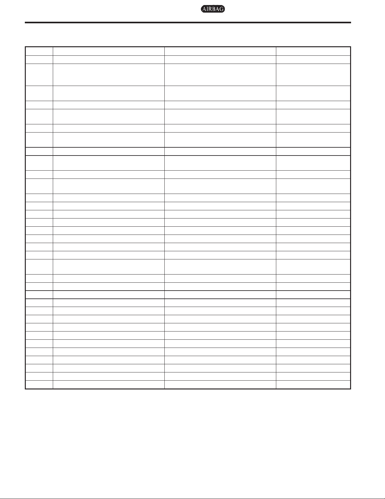
B: LIST OF DIAGNOSTIC TROUBLE CODE
Code Display screen Contents of diagnosis Ref. to
— Communication for initializing impossible Select monitor communication failure <Ref. to 4-4 [T10C0].>
Although no trouble code appears on the
— No trouble code
Open or short circuit in front right ABS
21
sensor circuit
22 Front right ABS sensor abnormal signal Front right ABS sensor abnormal signal <Ref. to 4-4 [T10I0].>
Open or short circuit in front left ABS sen-
23
sor circuit
24 Front left ABS sensor abnormal signal Front left ABS sensor abnormal signal <Ref. to 4-4 [T10J0].>
Open or short circuit in rear right ABS
25
sensor circuit
26 Rear right ABS sensor abnormal signal Rear right ABS sensor abnormal signal <Ref. to 4-4 [T10C0].>
Open or short circuit in rear left ABS sen-
27
sor circuit
28 Rear left ABS sensor abnormal signal Rear left ABS sensor abnormal signal <Ref. to 4-4 [T10L0].>
Abnormal ABS sensor signal on any one
29
of four sensor
31 Front right inlet valve malfunction Front right inlet valve malfunction <Ref. to 4-4 [T10N0].>
32 Front right outlet valve malfunction Front right outlet valve malfunction <Ref. to 4-4 [T10R0].>
33 Front left inlet valve malfunction Front left inlet valve malfunction <Ref. to 4-4 [T10O0].>
34 Front left outlet valve malfunction Front left outlet valve malfunction <Ref. to 4-4 [T10S0].>
35 Rear right inlet valve malfunction Rear right inlet valve malfunction <Ref. to 4-4 [T10P0].>
36 Rear right outlet valve malfunction Rear right outlet valve malfunction <Ref. to 4-4 [T10T0].>
37 Rear left inlet valve malfunction Rear left inlet valve malfunction <Ref. to 4-4 [T10Q0].>
38 Rear left outlet valve malfunction Rear left outlet valve malfunction <Ref. to 4-4 [T10U0].>
41 ABS control module malfunction
42 Power supply voltage too low Power supply voltage too low <Ref. to 4-4 [T10W0].>
42 Power supply voltage too high Power supply voltage too high <Ref. to 4-4 [T10X0].>
44 ABS-AT control (Non Controlled) ABS-AT control (Non Controlled) <Ref. to 4-4 [T10Y0].>
44 ABS-AT control (Controlled) ABS-AT control (Controlled) <Ref. to 4-4 [T10Z0].>
51 Valve relay malfunction Valve relay malfunction <Ref. to 4-4 [T10AA0].>
51 Valve relay ON failure Valve relay ON failure <Ref. to 4-4 [T10AB0].>
52 Open circuit in motor relay circuit Open circuit in motor relay circuit <Ref. to 4-4 [T10AC0].>
52 Motor relay ON failure Motor relay ON failure <Ref. to 4-4 [T10AD0].>
52 Motor malfunction Motor malfunction <Ref. to 4-4 [T10AE0].>
54 Stop light switch signal circuit malfunction Stop light switch signal circuit malfunction <Ref. to 4-4 [T10AF0].>
56 Open or short circuit in G sensor circuit Open or short circuit in G sensor circuit <Ref. to 4-4 [T10AG0].>
56 Battery short in G sensor circuit Battery short in G sensor circuit <Ref. to 4-4 [T10AH0].>
56 Abnormal G sensor high µ output Abnormal G sensor high µ output <Ref. to 4-4 [T10AI0].>
56 Detection of G sensor stick Detection of G sensor stick <Ref. to 4-4 [T10AJ0].>
NOTE:
High µ means high friction coefficient against road surface.
select monitor display, theABS warning
light remains on.
Open or short circuit in front right ABS
sensor circuit
Open or short circuit in front left ABS sensor circuit
Open or short circuit in rear right ABS
sensor circuit
Open or short circuit in rear left ABS sensor circuit
Abnormal ABS sensor signal on any one
of four
ABS control module and hydraulic control
unit malfunction
<Ref. to 4-4 [T10D0].>
<Ref. to 4-4 [T10E0].>
<Ref. to 4-4 [T10F0].>
<Ref. to 4-4 [T10K0].>
<Ref. to 4-4 [T10H0].>
<Ref. to 4-4 [T10M0].>
<Ref. to 4-4 [T10V0].>
81

4-4 [T10C0] DIAGNOSTICS
10. Diagnostics Chart with Select Monitor
C: COMMUNICATION FOR INITIALIZING IMPOSSIBLE
— SELECT MONITOR COMMUNICATION FAILURE —
DIAGNOSIS:
I Faulty harness connector
TROUBLE SYMPTOM:
I ABS warning light remains on.
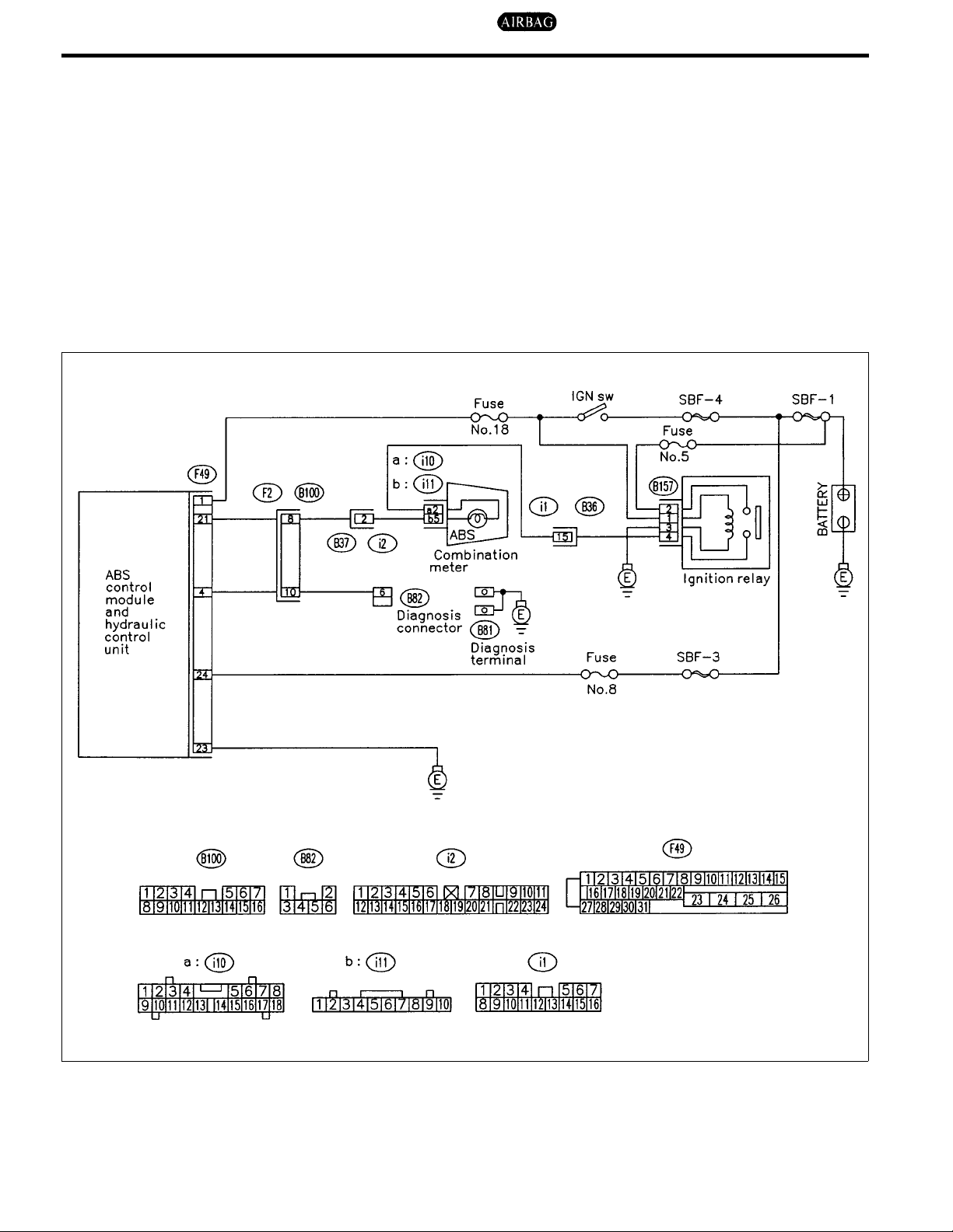
WIRING DIAGRAM:
82
S4M0292

[T10C6] 4-4DIAGNOSTICS
10. Diagnostics Chart with Select Monitor
10C1 : CHECK IGNITION SWITCH.
:
Is ignition switch ON?
: Go to step 10C2.
: Turn ignition switch to ON, and select
brake control mode using the select
monitor.
10C2 : CHECK GENERATOR.
1) Start the engine.
2) Idle the engine.
3) Measure voltage between generator and chassis ground.
Terminals
Generator B terminal (+) — Chassis
ground (−):
10C4 : CHECK COMMUNICATION OF
SELECT MONITOR.
Using the select monitor, check whether communication to other system (such as engine, AT, etc.)
can be executed normally.
:
Are the name and year of the system
displayed on the select monitor?
: Go to step 10C5.
: Repair select monitor communication
cable and connector.
10C5 : CHECK INSTALLATION OF
ABSCM&H/U CONNECTOR.
Turn ignition switch to OFF.
:
Is ABSCM&H/U connector inserted
into ABSCM&H/U until the clamp
locks onto it?
: Go to step 10C6.
: Insert ABSCM&H/U connector into
ABSCM&H/U until the clamp locks onto
it.
:
Is the voltage between 10 and 15 V?
: Go to step 10C3.
: Repair generator. <Ref. to 6-1 [W2A0].>
10C3 : CHECK BATTERY TERMINAL.
Turn ignition switch to OFF.
:
Is there poor contact at battery terminal?
: Repair battery terminal.
: Go to step 10C4.
B4M0430
10C6 : CHECK POWER SUPPLY OF
ABSCM&H/U.
1) Disconnect connector from ABSCM&H/U.
2) Start engine.
3) Idle the engine.
4) Measure voltage between ABSCM&H/U connector and chassis ground.
Connector & terminal
(F49) No. 1 (+) — Chassis ground (−):
B4M1234A
:
Is the voltage between 10 and 15 V?
: Go to step 10C7.
: Repair ABSCM&H/U power supply cir-
cuit.
83

4-4 [T10C7] DIAGNOSTICS
10. Diagnostics Chart with Select Monitor
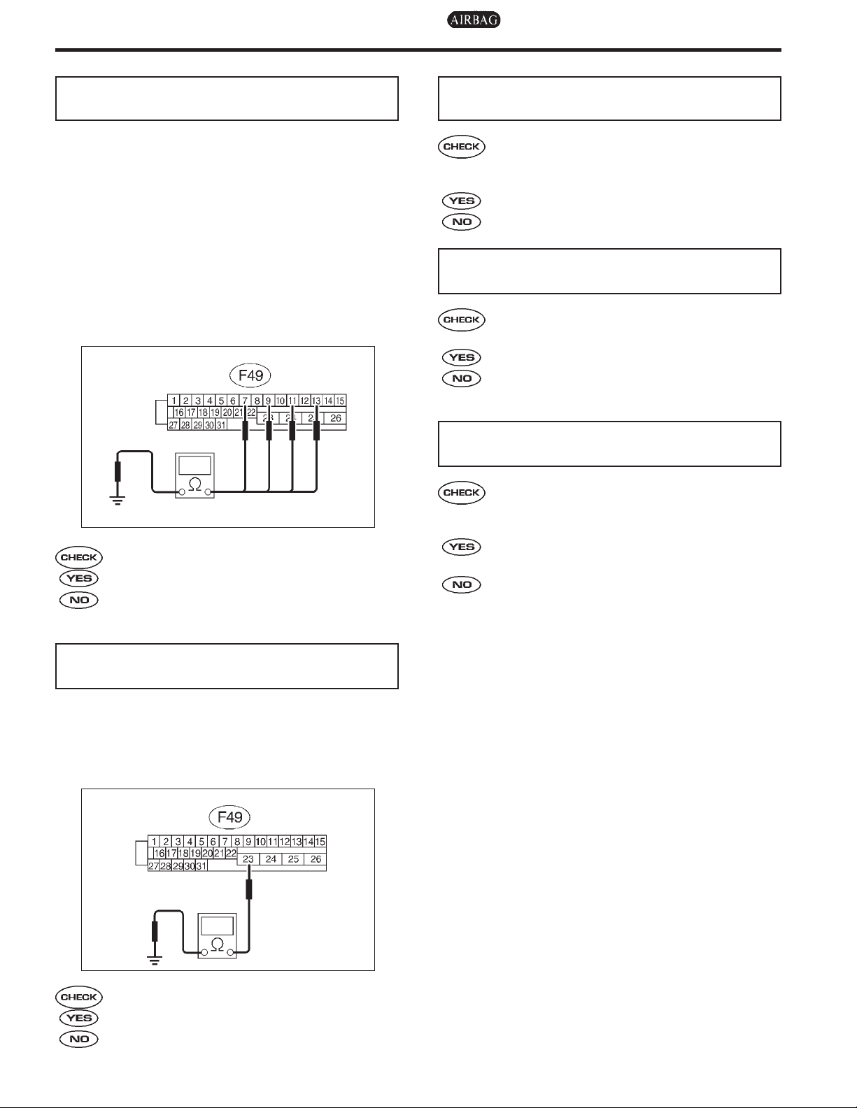
10C7 : CHECK GROUND CIRCUIT OF
ABSCM&H/U.
1) Turn ignition switch to OFF.
2) Measure resistance between ABSCM&H/U
connector and chassis ground.
Connector & terminal
(F49) No. 23 — Chassis ground:
B4M1243A
:
Is the resistance less than 0.5Ω?
: Repair harness/connector between
ABSCM&H/U and select monitor.
: Go to step 10C8.
10C9 : CHECK POOR CONTACT IN CON-
NECTORS.
:
Is there poor contact in connectors
between ABSCM&H/U and data link
connector? <Ref. to FOREWORD
[W3C1].>
: Repair connector.
: Replace ABSCM&H/U. <Ref. to 4-4
[W14A0].>
10C8 : CHECK HARNESS/CONNECTOR
BETWEEN ABSCM&H/U AND DATA
LINK CONNECTOR.
1) Turn ignition switch to OFF.
2) Measure resistance between ABSCM&H/U
connector and data link connector.
Connector & terminal
(F49) No. 20 — (B40) No. 5:
(F49) No. 5 — (B40) No. 4:
S4M0075A
:
Is the resistance less than 0.5Ω?
: Repair harness and connector between
ABSCM&H/U and data link connector.
: Go to step 10C9.
84

MEMO:
[T10C9] 4-4DIAGNOSTICS
10. Diagnostics Chart with Select Monitor
85
4-4 [T10D0] DIAGNOSTICS
10. Diagnostics Chart with Select Monitor
D: NO TROUBLE CODE
— ALTHOUGH NO TROUBLE CODE APPEARS ON THE SELECT MONITOR
DISPLAY, THE ABS WARNING LIGHT REMAINS ON. —
DIAGNOSIS:
I ABS warning light circuit is shorted.
TROUBLE SYMPTOM:
I ABS warning light remains on.
I NO TROUBLE CODE displayed on the select monitor.
NOTE:
When the ABS warning light is OFF and “NO TROUBLE CODE” is displayed on the select monitor, the
system is in normal condition.
WIRING DIAGRAM:
86
S4M0479
[T10D4] 4-4DIAGNOSTICS
10. Diagnostics Chart with Select Monitor
10D1 : CHECK WIRING HARNESS.
1) Turn ignition switch to OFF.
2) Disconnect connector (F2) from connector
(B100).
3) Turn ignition switch to ON.
:
Does the ABS warning light remain
off?
: Go to step 10D2.
: Repair front wiring harness.
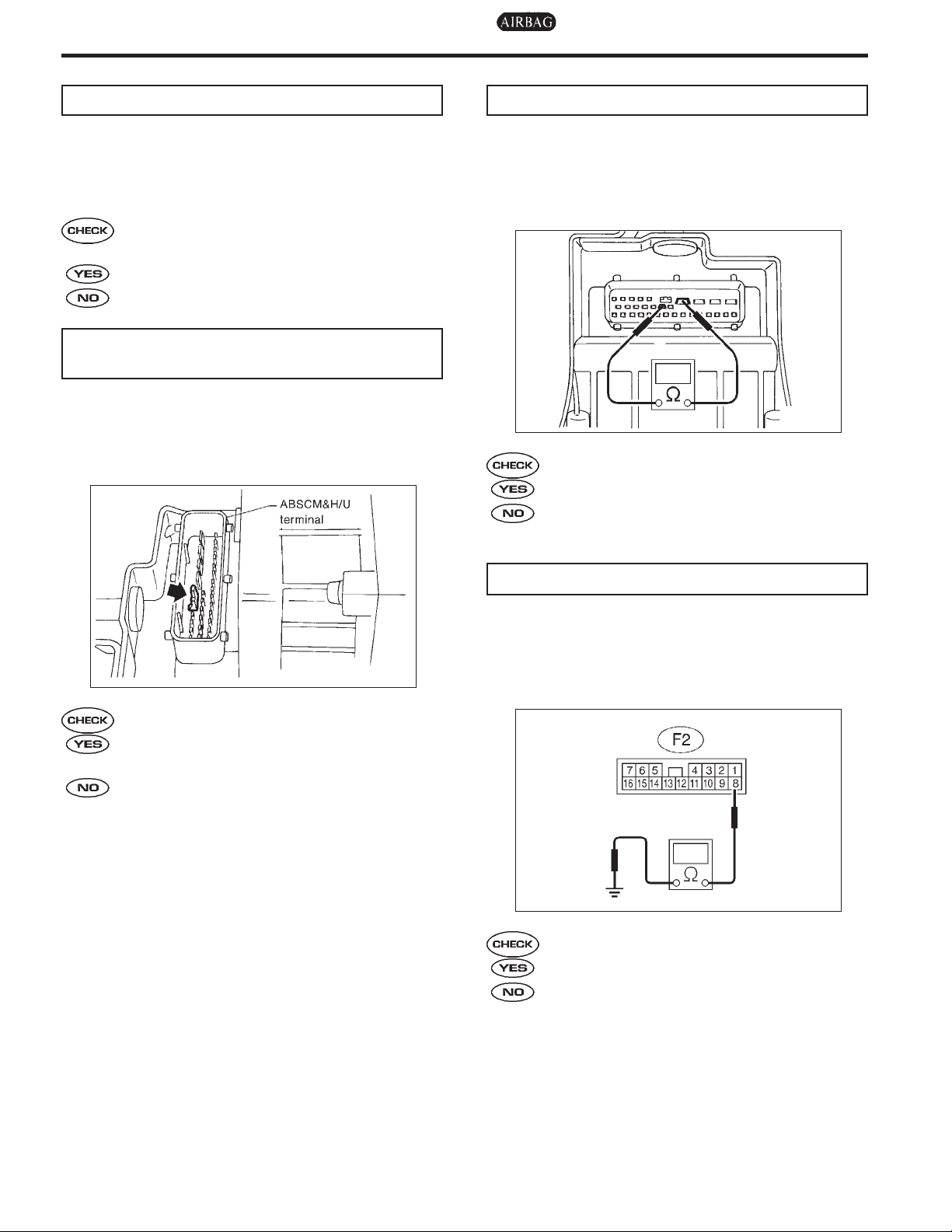
10D2 : CHECK PROJECTION AT
ABSCM&H/U.
1) Turn ignition switch to OFF.
2) Disconnect connector from ABSCM&H/U.
3) Check for broken projection at the
ABSCM&H/U terminal.
10D3 : CHECK ABSCM&H/U.
Measure resistance between ABSCM&H/U terminals.
Terminals
No. 21 — No. 23:
B4M1237A
:
Is the resistance more than 1 MΩ?
: Go to step 10D4.
: Replace ABSCM&H/U. <Ref. to 4-4
[W14A0].>
B4M1235A
:
Are the projection broken?
: Replace ABSCM&H/U. <Ref. to 4-4
[W14A0].>
: Go to step 10D3.
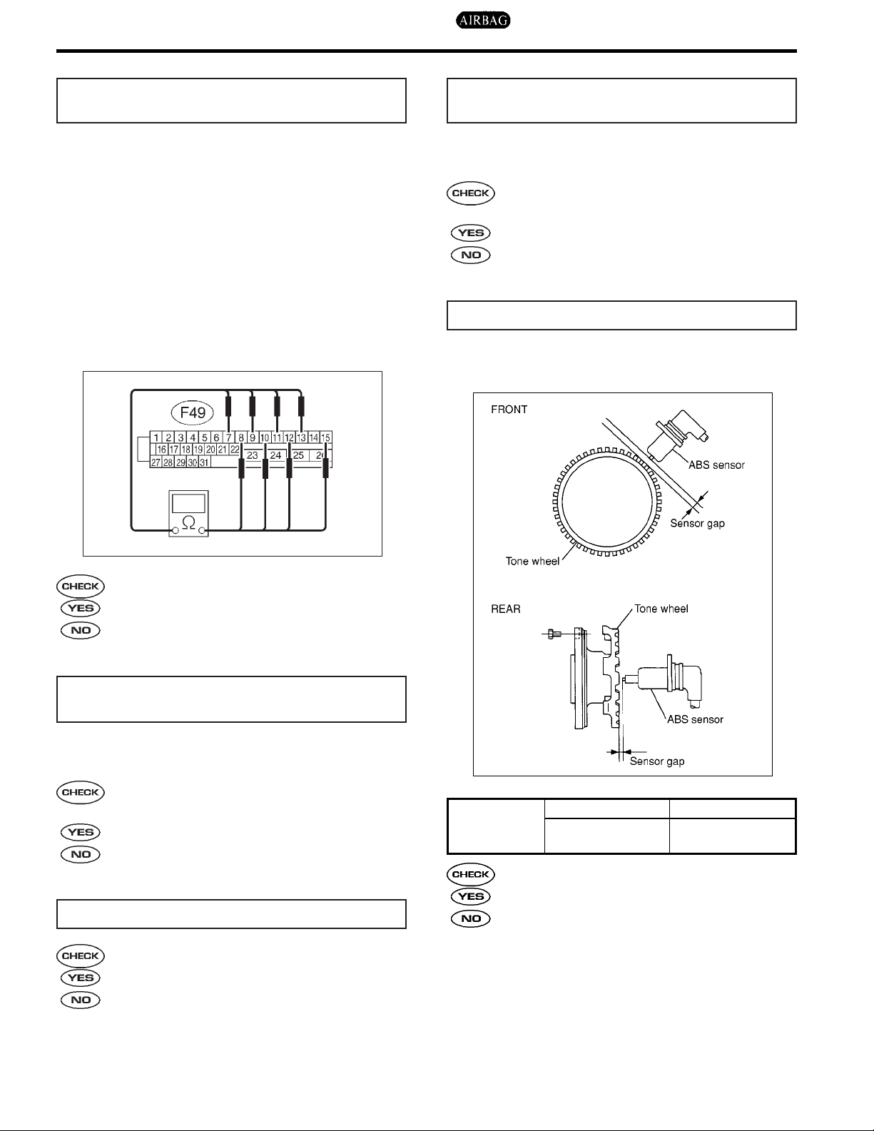
10D4 : CHECK WIRING HARNESS.
Measure resistance between connector (F2) and
chassis ground.
Connector & terminal
(F2) No. 8 — Chassis ground:
S4M0281A
:
Is the resistance less than 0.5Ω?
: Go to step 10D5.
: Repair harness.
87

4-4 [T10D5] DIAGNOSTICS
10. Diagnostics Chart with Select Monitor
10D5 : CHECK WIRING HARNESS.
1) Connect connector to ABSCM&H/U.
2) Measure resistance between connector (F2)
and chassis ground.
Connector & terminal
(F2) No. 8 — Chassis ground:
S4M0281A
:
Is the resistance more than 1 MΩ?
: Go to step 10D6.
: Repair harness.
10D6 : CHECK POOR CONTACT IN
ABSCM&H/U CONNECTOR.
:
Is there poor contact in ABSCM&H/U
connector? <Ref. to FOREWORD
[W3C1].>
: Repair connector.
: Replace ABSCM&H/U. <Ref. to 4-4
[W14A0].>
88

MEMO:
[T10D6] 4-4DIAGNOSTICS
10. Diagnostics Chart with Select Monitor
89

4-4 [T10E0] DIAGNOSTICS
10. Diagnostics Chart with Select Monitor
E: TROUBLE CODE 21 OPEN OR SHORT CIRCUIT IN FRONT RIGHT ABS
SENSOR CIRCUIT
F: TROUBLE CODE 23 OPEN OR SHORT CIRCUIT IN FRONT LEFT ABS
SENSOR CIRCUIT
G: TROUBLE CODE 25 OPEN OR SHORT CIRCUIT IN REAR RIGHT ABS
SENSOR CIRCUIT
H: TROUBLE CODE 27 OPEN OR SHORT CIRCUIT IN REAR LEFT ABS
SENSOR CIRCUIT
— ABNORMAL ABS SENSOR (OPEN OR SHORT CIRCUIT IN ABS SENSOR
CIRCUIT) —
DIAGNOSIS:
I Faulty ABS sensor (Broken wire, input voltage too high)
I Faulty harness connector
TROUBLE SYMPTOM:
I ABS does not operate.
90

WIRING DIAGRAM:
[T10H0] 4-4DIAGNOSTICS
10. Diagnostics Chart with Select Monitor
91
S4M0282

4-4 [T10H1] DIAGNOSTICS
10. Diagnostics Chart with Select Monitor
10H1 : CHECK OUTPUT OF ABS SENSOR
USING SELECT MONITOR.
1) Select “Current data display & Save” on the
select monitor.
2) Read the ABS sensor output corresponding to
the faulty system in the select monitor data display
mode.
:
Does the speed indicated on the display change in response to the
speedometer reading during
acceleration/deceleration when the
steering wheel is in the straightahead position?
: Go to step 10H2.
: Go to step 10H10.
10H2 : CHECK INSTALLATION OF ABS
SENSOR.
Tightening torque:
±
10 N·m (3.3±1.0 kg-m, 24±7 ft-lb)
32
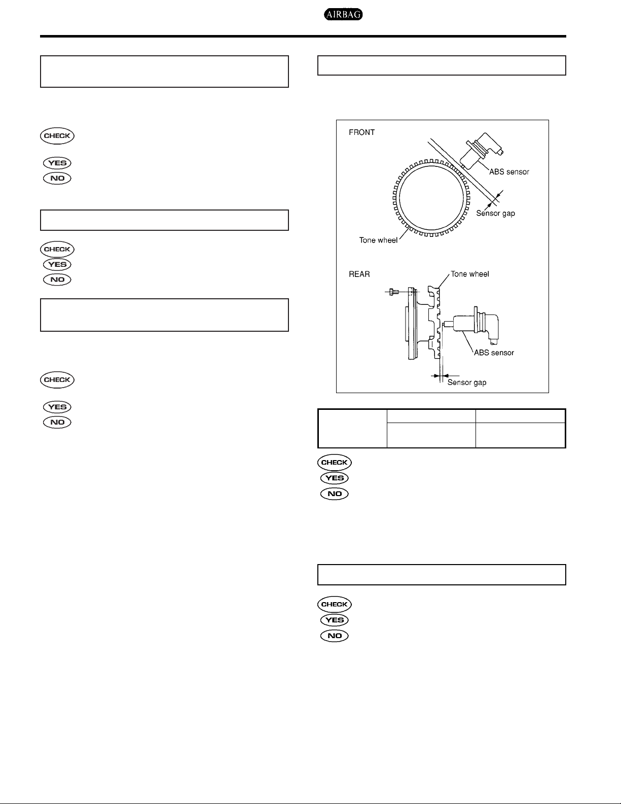
10H5 : CHECK ABS SENSOR GAP.
Measure tone wheel-to-pole piece gap over entire
perimeter of the wheel. <Ref. to 4-4 [W13C0].>
:
Are the ABS sensor installation bolts
tightened securely?
: Go to step 10H3.
: Tighten ABS sensor installation bolts
securely.
10H3 : CHECK TROUBLE CODE.
:
Is the trouble code 21 and/or 23?
: Go to step 10H5.
: Go to step 10H4.
10H4 : CHECK INSTALLATION OF REAR
TONE WHEEL.
Tightening torque:
±
3 N·m (1.3±0.3 kg-m, 9±2.2 ft-lb)
13
:
Are the rear tone wheel installation
bolts tightened securely?
: Go to step 10H5.
: Tightenrear tone wheel installationbolts
securely.
H4M1404A
Front wheel Rear wheel
Specifications
0.3 — 0.8 mm
(0.012 — 0.031 in)
:
Is the gap within the specifications?
0.7 — 1.2 mm
(0.028 — 0.047 in)
: Go to step 10H6.
: Adjust the gap.
NOTE:
Adjust the gap using spacers (Part No.
26755AA000). If spacers cannot correct the gap,
replace worn sensor or worn tone wheel.
10H6 : CHECK HUB RUNOUT.
Measure hub runout.
:
Is the runout less than 0.05 mm
(0.0020 in)?
: Go to step 10H7.
: Repair hub.
92

[T10H11] 4-4DIAGNOSTICS
10. Diagnostics Chart with Select Monitor
10H7 : CHECK POOR CONTACT IN CON-
NECTORS.
Turn ignition switch to OFF.
:
Is there poor contact in connectors
between ABSCM&H/U and ABS sensor? <Ref. to FOREWORD [W3C1].>
: Repair connector.
: Go to step 10H8.
10H8 : CHECK ABSCM&H/U.
1) Connect all connectors.
2) Erase the memory.
3) Perform inspection mode.
4) Read out the trouble code.
:
Is the same trouble code as in the
current diagnosis still being output?
: Replace ABSCM&H/U. <Ref. to 4-4
[W14A0].>
: Go to step 10H9.
10H9 : CHECK ANY OTHER TROUBLE
CODES APPEARANCE.
10H10 : CHECK FRONT ABS SENSOR.
1) Turn ignition switch to OFF.
2) Disconnect connector from front ABS sensor.
3) Measure resistance of front ABS sensor connector terminals.
Terminals
RH No. 1 — No. 2:
LH No. 1 — No. 2:
B4M0806
:
Is the resistance between 1.0 and 1.5
Ω
?
k
: Go to step 10H11.
: Replace front ABS sensor.
:
Are other trouble codes being output?
: Proceed with the diagnosis correspond-
ing to the trouble code.
: A temporary poor contact.
NOTE:
Check harness and connectors between
ABSCM&H/U and ABS sensor.
10H11 : CHECK REAR ABS SENSOR.
1) Turn ignition switch to OFF.
2) Disconnect connector from rear ABS sensor.
3) Measure resistance of rear ABS sensor connector terminals.
Terminals
RH No. 1 — No. 2:
LH No. 1 — No. 2:
B4M0806
:
Is the resistance between 0.8 and 1.2
Ω
?
k
: Go to step 10H12.
: Replace rear ABS sensor.
93

4-4 [T10H12] DIAGNOSTICS
10. Diagnostics Chart with Select Monitor
10H12 : CHECK BATTERY SHORT OF ABS
SENSOR.
1) Disconnect connector from ABSCM&H/U.
2) Measure voltage between ABS sensor and
chassis ground.
Terminals
Front RH No. 1 (+) — Chassis ground (−):
Front LH No. 1 (+) — Chassis ground (−):
Rear RH No. 1 (+) — Chassis ground (−):
Rear LH No. 1 (+) — Chassis ground (−):
B4M0807
10H14 : CHECK TROUBLE CODE.
:
Is the trouble code 21 and/or 23?
: Go to step 10H15.
: Go to step 10H16.
10H15 : CHECK HARNESS/CONNECTOR
BETWEEN ABSCM&H/U AND ABS
SENSOR.
1) Turn ignition switch to OFF.
2) Connect connector to ABS sensor.
3) Measure resistance between ABSCM&H/U
connector terminals.
Connector & terminal
Trouble code 21 / (F49) No. 11 — No. 12:
Trouble code 23 / (F49) No. 9 — No. 10:
:
Is the voltage less than 1 V?
: Go to step 10H13.
: Replace ABS sensor.
10H13 : CHECK BATTERY SHORT OF ABS
SENSOR.
1) Turn ignition switch to ON.
2) Measure voltage between ABS sensor and
chassis ground.
Terminals
Front RH No. 1 (+) — Chassis ground (−):
Front LH No. 1 (+) — Chassis ground (−):
Rear RH No. 1 (+) — Chassis ground (−):
Rear LH No. 1 (+) — Chassis ground (−):
H4M1392A
:
Is the resistance between 1.0 and 1.5
Ω
?
k
: Go to step 10H17.
: Repair harness/connector between
ABSCM&H/U and ABS sensor.
:
Is the voltage less than 1 V?
: Go to step 10H14.
: Replace ABS sensor.
B4M0807
94

[T10H17] 4-4DIAGNOSTICS
10. Diagnostics Chart with Select Monitor
10H16 : CHECK HARNESS/CONNECTOR
BETWEEN ABSCM&H/U AND ABS
SENSOR.
1) Turn ignition switch to OFF.
2) Connect connector to ABS sensor.
3) Measure resistance between ABSCM&H/U
connector terminals.
Connector & terminal
Trouble code 25 / (F49) No. 13 — No. 15:
Trouble code 27 / (F49) No. 7 — No. 8:
S4M0484A
10H17 : CHECK BATTERY SHORT OF HAR-
NESS.
Measure voltage between ABSCM&H/U connector
and chassis ground.
Connector & terminal
Trouble code 21 / (F49) No. 11 (+) —
Chassis ground (−):
Trouble code 23 / (F49) No. 9 (+) — Chassis ground (−):
Trouble code 25 / (F49) No. 13 (+) —
Chassis ground (−):
Trouble code 27 / (F49) No. 7 (+) — Chassis ground (−):
:
Is the resistance between 0.8 and 1.2
Ω
?
k
: Go to step 10H17.
: Repair harness/connector between
ABSCM&H/U and ABS sensor.
S4M0285A
:
Is the voltage less than 1 V?
: Go to step 10H18.
: Repair harness between ABSCM&H/U
and ABS sensor.
95
4-4 [T10H18] DIAGNOSTICS
10. Diagnostics Chart with Select Monitor
10H18 : CHECK BATTERY SHORT OF HAR-
NESS.
1) Turn ignition switch to ON.
2) Measure voltage between ABSCM&H/U con-
nector and chassis ground.
Connector & terminal
Trouble code 21 / (F49) No. 11 (+) —
Chassis ground (−):
Trouble code 23 / (F49) No. 9 (+) — Chassis ground (−):
Trouble code 25 / (F49) No. 13 (+) —
Chassis ground (−):
Trouble code 27 / (F49) No. 7 (+) — Chassis ground (−):
10H21 : CHECK INSTALLATION OF REAR
TONE WHEEL.
Tightening torque:
±
3 N·m (1.3±0.3 kg-m, 9±2.2 ft-lb)
13
:
Are the rear tone wheel installation
bolts tightened securely?
: Go to step 10H22.
: Tightenrear tone wheel installationbolts
securely.
10H22 : CHECK ABS SENSOR GAP.
Measure tone wheel-to-pole piece gap over entire
perimeter of the wheel. <Ref. to 4-4 [W13C0].>
S4M0283A
:
Is the voltage less than 1 V?
: Go to step 10H19.
: Repair harness between ABSCM&H/U
and ABS sensor.
10H19 : CHECK INSTALLATION OF ABS
SENSOR.
Tightening torque:
±
10 N·m (3.3±1.0 kg-m, 24±7 ft-lb)
32
:
Are the ABS sensor installation bolts
tightened securely?
: Go to step 10H20.
: Tighten ABS sensor installation bolts
securely.
10H20 : CHECK TROUBLE CODE.
:
Is the trouble code 21 and/or 23?
: Go to step 10H22.
: Go to step 10H21.
H4M1404A
Front wheel Rear wheel
Specifications
0.3 — 0.8 mm
(0.012 — 0.031 in)
:
Is the gap within the specifications?
0.7 — 1.2 mm
(0.028 — 0.047 in)
: Go to step 10H23.
: Adjust the gap.
NOTE:
Adjust the gap using spacers (Part No.
26755AA000). If spacers cannot correct the gap,
replace worn sensor or worn tone wheel.
96

[T10H26] 4-4DIAGNOSTICS
10. Diagnostics Chart with Select Monitor
10H23 : CHECK HUB RUNOUT.
Measure hub runout.
:
Is the runout less than 0.05 mm
(0.0020 in)?
: Go to step 10H24.
: Repair hub.
10H24 : CHECK GROUND SHORT OF ABS
SENSOR.
1) Turn ignition switch to OFF.
2) Measure resistance between ABS sensor and
chassis ground.
Terminals
Front RH No. 1 — Chassis ground:
Front LH No. 1 — Chassis ground:
Rear RH No. 1 — Chassis ground:
Rear LH No. 1 — Chassis ground:
10H25 : CHECK GROUND SHORT OF HAR-
NESS.
1) Turn ignition switch to OFF.
2) Connect connector to ABS sensor.
3) Measure resistance between ABSCM&H/U
connector terminal and chassis ground.
Connector & terminal
Trouble code 21 / (F49) No. 11 — Chassis
ground:
Trouble code 23 / (F49) No. 9 — Chassis
ground:
Trouble code 25 / (F49) No. 13 — Chassis
ground:
Trouble code 27 / (F49) No. 7 — Chassis
ground:
B4M0818
:
Is the resistance more than 1 MΩ?
: Go to step 10H25.
: Replace ABS sensor and ABSCM&H/U.
<Ref. to 4-4 [W14A0].>
S4M0285A
:
Is the resistance more than 1 MΩ?
: Go to step 10H26.
: Repair harness between ABSCM&H/U
and ABS sensor. And replace
ABSCM&H/U. <Ref. to 4-4 [W14A0].>
10H26 : CHECK POOR CONTACT IN CON-
NECTORS.
:
Is there poor contact in connectors
between ABSCM&H/U and ABS sensor? <Ref. to FOREWORD [W3C1].>
: Repair connector.
: Go to step 10H27.
97

4-4 [T10H27] DIAGNOSTICS
10. Diagnostics Chart with Select Monitor
10H27 : CHECK ABSCM&H/U.
1) Connect all connectors.
2) Erase the memory.
3) Perform inspection mode.
4) Read out the trouble code.
:
Is the same trouble code as in the
current diagnosis still being output?
: Replace ABSCM&H/U. <Ref. to 4-4
[W14A0].>
: Go to step 10H28.
10H28 : CHECK ANY OTHER TROUBLE
CODES APPEARANCE.
:
Are other trouble codes being output?
: Proceed with the diagnosis correspond-
ing to the trouble code.
: A temporary poor contact.
NOTE:
Check harness and connectors between
ABSCM&H/U and ABS sensor.
98

MEMO:
[T10H28] 4-4DIAGNOSTICS
10. Diagnostics Chart with Select Monitor
99

4-4 [T10I0] DIAGNOSTICS
10. Diagnostics Chart with Select Monitor
I: TROUBLE CODE 22 FRONT RIGHT ABS SENSOR ABNORMAL SIGNAL
J: TROUBLE CODE 24 FRONT LEFT ABS SENSOR ABNORMAL SIGNAL
K: TROUBLE CODE 26 REAR RIGHT ABS SENSOR ABNORMAL SIGNAL
L: TROUBLE CODE 28 REAR LEFT ABS SENSOR ABNORMAL SIGNAL
— ABNORMAL ABS SENSOR (ABS SENSOR ABNORMAL SIGNAL) —
DIAGNOSIS:
I Faulty ABS sensor signal (noise, irregular signal, etc.)
I Faulty harness/connector
TROUBLE SYMPTOM:
I ABS does not operate.
WIRING DIAGRAM:
100
S4M0282
[T10L7] 4-4DIAGNOSTICS
10. Diagnostics Chart with Select Monitor
10L1 : CHECK OUTPUT OF ABS SENSOR
USING SELECT MONITOR.
1) Select “Current data display & Save” on the
select monitor.
2) Read the ABS sensor output corresponding to
the faulty system in the select monitor data display
mode.
:
Does the speed indicated on the display change in response to the
speedometer reading during
acceleration/deceleration when the
steering wheel is in the straightahead position?
: Go to step 10L2.
: Go to step 10L8.
10L2 : CHECK POOR CONTACT IN CON-
NECTORS.
Turn ignition switch to OFF.
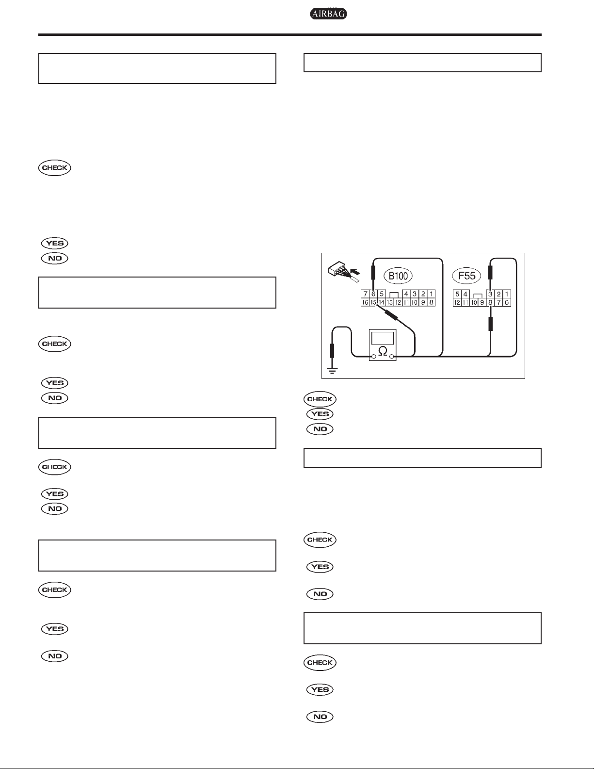
10L5 : CHECK SHIELD CIRCUIT.
1) Turn ignition switch to OFF.
2) Connect all connectors.
3) Measure resistance between shield connector
and chassis ground.
Connector & terminal
Trouble code 22 / (B100) No. 15 — Chassis ground:
Trouble code 24 / (B100) No. 6 — Chassis
ground:
Trouble code 26 / (F55) No. 8 — Chassis
ground:
Trouble code 28 / (F55) No. 3 — Chassis
ground:
:
Is there poor contact in connectors
between ABSCM&H/U and ABS sensor? <Ref. to FOREWORD [W3C1].>
: Repair connector.
: Go to step 10L3.
10L3 : CHECK SOURCES OF SIGNAL
NOISE.
:
Is the car telephone or the wireless
transmitter properly installed?
: Go to step 10L4.
: Properly install the car telephone or the
wireless transmitter.
10L4 : CHECK SOURCES OF SIGNAL
NOISE.
:
Are noise sources (such as an
antenna) installed near the sensor
harness?
: Install the noise sources apart from the
sensor harness.
: Go to step 10L5.
H4M1297A
:
Is the resistance less than 0.5Ω?
: Go to step 10L6.
: Repair shield harness.
10L6 : CHECK ABSCM&H/U.
1) Connect all connectors.
2) Erase the memory.
3) Perform inspection mode.
4) Read out the trouble code.
:
Is the same trouble code as in the
current diagnosis still being output?
: Replace ABSCM&H/U. <Ref. to 4-4
[W14A0].>
: Go to step 10L7.
10L7 : CHECK ANY OTHER TROUBLE
CODES APPEARANCE.
:
Are other trouble codes being output?
: Proceed with the diagnosis correspond-
ing to the trouble code.
: A temporary noise interference.
101
4-4 [T10L8] DIAGNOSTICS
10. Diagnostics Chart with Select Monitor
10L8 : CHECK INSTALLATION OF ABS
SENSOR.
Tightening torque:
±
10 N·m (3.3±1.0 kg-m, 24±7 ft-lb)
32
:
Are the ABS sensor installation bolts
tightened securely?
: Go to step 10L9.
: Tighten ABS sensor installation bolts
securely.
10L9 : CHECK TROUBLE CODE.
:
Is the trouble code 22 and/or 24?
: Go to step 10L11.
: Go to step 10L10.
10L10 : CHECK INSTALLATION OF REAR
TONE WHEEL.
Tightening torque:
13
±
3 N·m (1.3±0.3 kg-m, 9±2.2 ft-lb)
:
Are the rear tone wheel installation
bolts tightened securely?
: Go to step 10L11.
: Tightenrear tone wheel installationbolts
securely.
10L11 : CHECK ABS SENSOR GAP.
Measure tone wheel to pole piece gap over entire
perimeter of the wheel. <Ref. to 4-4 [W13C0].>
H4M1404A
Front wheel Rear wheel
Specifications
0.3 — 0.8 mm
(0.012 — 0.031 in)
0.7 — 1.2 mm
(0.028 — 0.047 in)
:
Is the gap within the specifications?
: Go to step 10L12.
: Adjust the gap.
NOTE:
Adjust the gap using spacer (Part No.
26755AA000). If spacers cannot correct the gap,
replace worn sensor or worn tone wheel.
10L12 : PREPARE OSCILLOSCOPE.
:
Is an oscilloscope available?
: Go to step 10L13.
: Go to step 10L14.
102

[T10L16] 4-4DIAGNOSTICS
10. Diagnostics Chart with Select Monitor
10L13 : CHECK ABS SENSOR SIGNAL.
1) Raise all four wheels of ground.
2) Turn ignition switch to OFF.
3) Connect the oscilloscope to the connector.
4) Turn ignition switch to ON.
5) Rotate wheels and measure voltage at specified frequency.
NOTE:
When this inspection is completed, the
ABSCM&H/U sometimes stores the trouble code
29.
Connector & terminal
Trouble code 22 / (B100) No. 5 (+) — No.
14 (−):
Trouble code 24 / (B100) No. 7 (+) — No.
16 (−):
Trouble code 26 / (F55) No. 6 (+) — No. 7
(−):
Trouble code 28 / (F55) No. 1 (+) — No. 2
(−):
10L14 : CHECK CONTAMINATION OF ABS
SENSOR OR TONE WHEEL.
Remove disc rotoror drum from hub inaccordance
with trouble code.
:
Is the ABS sensor pole piece or the
tone wheel contaminated by dirt or
other foreign matter?
: Thoroughly remove dirt or other foreign
matter.
: Go to step 10L15.
10L15 : CHECK DAMAGE OF ABS SEN-
SOR OR TONE WHEEL.
:
Are there broken or damaged in the
ABS sensor pole piece or the tone
wheel?
: Replace ABS sensor or tone wheel.
: Go to step 10L16.
H4M1296A
:
Is oscilloscope pattern smooth, as
shown in figure?
: Go to step 10L17.
: Go to step 10L14.
10L16 : CHECK HUB RUNOUT.
Measure hub runout.
:
Is the runout less than 0.05 mm
(0.0020 in)?
: Go to step 10L17.
: Repair hub.
103

4-4 [T10L17] DIAGNOSTICS
10. Diagnostics Chart with Select Monitor
10L17 : CHECK RESISTANCE OF FRONT
ABS SENSOR.
1) Turn ignition switch to OFF.
2) Disconnect connector from front ABS sensor.
3) Measure resistance between front ABS sensor
connector terminals.
Terminals
RH No. 1 — No. 2:
LH No. 1 — No. 2:
B4M0806
:
Is the resistance between 1.0 and 1.5
Ω
?
k
: Go to step 10L18.
: Replace front ABS sensor.
10L18 : CHECK RESISTANCE OF REAR
ABS SENSOR.
1) Turn ignition switch to OFF.
2) Disconnect connector from rear ABS sensor.
3) Measure resistance between rear ABS sensor
connector terminals.
Terminals
RH No. 1 — No. 2:
LH No. 1 — No. 2:
10L19 : CHECK GROUND SHORT OF ABS
SENSOR.
Measure resistance between ABS sensor and
chassis ground.
Terminals
Front RH No. 1 — Chassis ground:
Front LH No. 1 — Chassis ground:
Rear RH No. 1 — Chassis ground:
Rear LH No. 1 — Chassis ground:
B4M0818
:
Is the resistance more than 1 MΩ?
: Go to step 10L20.
: Replace ABS sensor.
10L20 : CHECK TROUBLE CODE.
:
Is the trouble code 22 and/or 24?
: Go to step 10L21.
: Go to step 10L22.
B4M0806
:
Is the resistance between 0.8 and 1.2
k
Ω
?
: Go to step 10L19.
: Replace rear ABS sensor.
104

[T10L22] 4-4DIAGNOSTICS
10. Diagnostics Chart with Select Monitor
10L21 : CHECK HARNESS/CONNECTOR
BETWEEN ABSCM&H/U AND ABS
SENSOR.
1) Connect connector to ABS sensor.
2) Disconnect connector from ABSCM&H/U.
3) Measure resistance at ABSCM&H/U connector
terminals.
Connector & terminal
Trouble code 22 / (F49) No. 11 — No. 12:
Trouble code 24 / (F49) No. 9 — No. 10:
H4M1392A
10L22 : CHECK HARNESS/CONNECTOR
BETWEEN ABSCM&H/U AND ABS
SENSOR.
1) Connect connector to ABS sensor.
2) Disconnect connector from ABSCM&H/U.
3) Measure resistance at ABSCM&H/U connector
terminals.
Connector & terminal
Trouble code 26 / (F49) No. 13 — No. 15:
Trouble code 28 / (F49) No. 7 — No. 8:
S4M0484A
:
Is the resistance between 1.0 and 1.5
Ω
?
k
: Go to step 10L23.
: Repair harness/connector between
ABSCM&H/U and ABS sensor.
:
Is the resistance between 0.8 and 1.2
Ω
?
k
: Go to step 10L23.
: Repair harness/connector between
ABSCM&H/U and ABS sensor.
105
4-4 [T10L23] DIAGNOSTICS
10. Diagnostics Chart with Select Monitor
10L23 : CHECK GROUND SHORT OF HAR-
NESS.
Measure resistance between ABSCM&H/U connector and chassis ground.
Connector & terminal
Trouble code 22 / (F49) No. 11 — Chassis
ground:
Trouble code 24 / (F49) No. 9 — Chassis
ground:
Trouble code 26 / (F49) No. 13 — Chassis
ground:
Trouble code 28 / (F49) No. 7 — Chassis
ground:
S4M0285A
:
Is the resistance more than 1 MΩ?
: Go to step 10L24.
: Repair harness/connector between
ABSCM&H/U and ABS sensor.
10L25 : CHECK POOR CONTACT IN CON-
NECTORS.
:
Is there poor contact in connectors
between ABSCM&H/U and ABS sensor? <Ref. to FOREWORD [W3C1].>
: Repair connector.
: Go to step 10L26.
10L26 : CHECK SOURCES OF SIGNAL
NOISE.
:
Is the car telephone or the wireless
transmitter properly installed?
: Go to step 10L27.
: Properly install the car telephone or the
wireless transmitter.
10L27 : CHECK SOURCES OF SIGNAL
NOISE.
:
Are noise sources (such as an
antenna) installed near the sensor
harness?
: Install the noise sources apart from the
sensor harness.
: Go to step 10L28.
10L24 : CHECK GROUND CIRCUIT OF
ABSCM&H/U.
Measure resistance between ABSCM&H/U and
chassis ground.
Connector & terminal
(F49) No. 23 — Chassis ground:
B4M1243A
:
Is the resistance less than 0.5Ω?
: Go to step 10L25.
: Repair ABSCM&H/U ground harness.
106
 Loading...