

Subaru Forester 2004 User Manual

ABS CONTROL MODULE AND HYDRAULIC CONTROL UNIT (ABSCM&H/U)
ABS
2. ABS Control Module and Hydraulic Control Unit (ABSCM&H/U)
A: REMOVAL
1) Disconnect the ground cable from battery.
2) Remove the air intake duct to facilitate removal
of ABSCM&H/U.
3) Use an air gun to get rid of water around the AB-
SCM&H/U.
NOTE:
Contact will be insufficient if the terminal gets wet.
4) Remove the ground cable from ABSCM&H/U.
5) Pull off the lock of ABSCM&H/U connector to re-
move it.
•Do not let water get into the connector.
ABS00132
B: INSTALLATION
1) Install the ABSCM&H/U bracket.
Tightening torque:
33 N·m (3.4 kgf-m, 24.6 ft-lb)
2) Apply a coat of anti-corrosive wax to the bracket
attaching bolt.
3) Align the width across flat portion of ABSCM& H/
U side stud bolt with the bolt hole groove on bracket, and then install the ABSCM&H/U.
NOTE:
Confirm the specification mark of ABSCM&H/U.
ABS00131
6) Disconnect the connector from ABSCM&H/U.
CAUTION:
Do not pull the harness when disconnecting the
connector.
7) Unlock the cable clip.
8) Disconnect the brake pipes from ABSCM&H/U.
9) Wrap the brake pipes with vinyl bag to avoid
spilling brake fluid on vehicle body.
CAUTION:
•Brake fluid spilt on the vehicle body will harm
the painted surface; wash away quickly with
water if spilt.
10) Remove the ABSCM&H/U from engine com-
partment.
CAUTION:
•ABSCM&H/U cannot be disassembled. Do
not attempt to loosen bolts and nuts.
•Do not drop or bump the ABSCM&H/U.
•Do not turn the ABSCM&H/U upside down or
place it on its side.
•Be careful to prevent foreign particles from
getting into ABSCM&H/U.
Tightening torque:
18 N·m (1.8 kgf-m, 13.0 ft-lb)
ABS00132
4) Connect the brake pipes to their correct ABSCM&H/U connections.
Tightening torque:
15 N·m (1.5 kgf-m, 10.8 ft-lb)
5) Using the cable clip, secure the ABSCM&H/U
harness to bracket.
6) Connect the connector to ABSCM&H/U.
NOTE:
•Be sure to remove all foreign matter from inside
of the connector before connecting.
•Ensure that the ABSCM&H/U connector is securely locked.
7) Connect the ground cable to ABSCM&H/U, and
then apply anti-corrosive wax.
8) Install the air intake duct.
9) Bleed air from the brake system.
ABS-7

ABS CONTROL MODULE AND HYDRAULIC CONTROL UNIT (ABSCM&H/U)
ABS
C: INSPECTION
1) Check the connected and fixed condition of con-
nector.
2) Check specifications of the mark with AB-
SCM&H/U.
Mark Model
CO AT
CP MT
(1)
ABS00133
(1) Mark
1. CHECKING THE HYDRAULIC UNIT ABS
OPERATION BY PRESSURE GAUGE
1) Lift-up the vehicle and remove the wheels.
2) Disconnect the air bleeder screws from the FL
and FR caliper bodies.
3) Connect two pressure gauges to the FL and FR
caliper bodies.
CAUTION:
•Pressure gauges used exclusively for brake
fluid must be used.
•Do not employ pressure gauge previously
used for transmission oil pressure since the
piston seal is expanded which may lead to malfunction of the brake.
NOTE:
Wrap sealing tape around the pressure gauge.
compression, and then the FR side performs decompression, holding and compression.
7) Read values indicated on the pressure gauge
and check if the fluctuation of the values between
decompression and compression meets the standard values. Also check if any irregular brake pedal
tightness is felt.
Front wheel Rear wheel
Initial value
Decompressed
Compressed
3,500 kPa
(35 kgf/cm
psi)
500 kPa
(5 kgf/cm
or less
3,500 kPa
(35 kgf/cm
psi)
or more
2
, 498
2
, 71 psi)
2
, 498
3,500 kPa
(35 kgf/cm2, 498
psi)
500 kPa
(5 kgf/cm2, 71 psi)
or less
3,500 kPa
(35 kgf/cm2, 498
psi)
or more
8) Remove the pressure gauges from FL and FR
caliper bodies.
9) Remove the air bleeder screws from the RL and
RR caliper bodies.
10) Connect the air bleeder screws to the FL and
FR caliper bodies.
11) Connect two pressure gauges to the RL and
RR caliper bodies.
12) Bleed air from the FL and FR caliper bodies.
13) Perform the ABS sequence control.
<Ref. to ABS-10, ABS Sequence Control.>
14) When the hydraulic unit begins to work, at first
the RR side performs decompression, holding and
compression, and then the RL side performs decompression, holding and compression.
15) Read values indicated on the pressure gauges
and check if they meet the standard value.
16) After checking, remove the pressure gauges
from caliper bodies.
17) Connect the air bleeder screws to RL and RR
caliper bodies.
18) Bleed air from the brake system.
ABS00134
4) Bleed air from the pressure gauges.
5) Perform the ABS sequence control.
<Ref. to ABS-10, ABS Sequence Control.>
6) When the hydraulic unit begins to work and first
the FL side performs decompression, holding and
ABS-8

ABS CONTROL MODULE AND HYDRAULIC CONTROL UNIT (ABSCM&H/U)
ABS
2. CHECKING THE HYDRAULIC UNIT ABS
OPERATION WITH BRAKE TESTER
1) In the case of AWD AT model, install a spare
fuse with the FWD connector in the main fuse box
to simulate FWD model.
(1)
(1) Main fuse box
(2) FWD connector
NOTE:
The AWD circuit of MT model can not be disabled
because viscous coupling is used inside center differential.
2) Prepare for operating the ABS sequence control.
<Ref. to ABS-10, ABS Sequence Control.>
3) Set the front wheels or rear wheels on the brake
tester and set the select lever’s position at “N”
range.
(2)
ABS00135
6) Hydraulic unit begins to work; and check the following working sequence.
(1) The FL side performs decompression, holding and compression in sequence, and subsequently the FR side repeats the cycle.
(2) The RR side performs decompression, holding and compression in sequence, and subsequently the RL side repeats the cycle.
7) Read values indicated on the brake tester and
check if the fluctuation of values, while decompressed and compressed, meet the standard values.
Front wheel Rear wheel
Initial value
Decompressed
Compressed
1,000 N
(100 kgf, 221 lb)
500 N
(50 kgf, 110 lb)
or less
1,000 N
(100 kgf, 221 lb)
or more
1,000 N
(100 kgf, 221 lb)
500 N
(50 kgf, 110 lb)
or less
1,000 N
(100 kgf, 221 lb)
or more
8) After checking, also check if any irregular brake
pedal tightness is felt.
(1)
ABS00136
(1)
ABS00137
(1) Brake tester
4) Operate the brake tester.
5) Perform the ABS sequence control.
<Ref. to ABS-10, ABS Sequence Control.>
ABS-9

ABS
ABS SEQUENCE CONTROL
3. ABS Sequence Control
A: OPERATION
1) Under the ABS sequence control, after the hy-
draulic unit solenoid valve is driven, the operation
of the hydraulic unit can be checked by means of
the brake tester or pressure gauge.
2) ABS sequence control can be started by diagno-
sis connector or SUBARU Select Monitor.
1. ABS SEQUENCE CONTROL WITH DIAG-
NOSIS CONNECTOR
1) Turn the ignition switch to OFF.
2) Connect the diagnosis terminal to terminal No. 6
of the diagnosis connector under driver’s seat instrument panel lower cover.
(1)
(4)
(2)
(1) Diagnosis connector
(2) Diagnosis terminals
(3) Terminal No. 3
(4) Terminal No. 6
3) Turn the ignition switch to ON.
4) Confirm that start code (code 11) is only dis-
played.
5) Turn the ignition switch to OFF.
6) Connect the diagnosis terminals to terminals No.
6 and No. 3 of the diagnosis connector.
7) Set the speed of all wheels at 4 km/h (2 MPH) or
less.
8) Turn the ignition switch to ON.
9) Within 0.5 seconds after the ABS warning light
goes out, depress the brake pedal and hold it depressed.
NOTE:
Engine must not operate.
CAUTION:
Do not depress the clutch pedal in case of model with hill holder.
10) After completion of ABS sequence control, turn
the ignition switch to OFF.
(3)
ABS00138
2. ABS SEQUENCE CONTROL WITH SUBARU SELECT MONITOR
NOTE:
•In the event of any trouble, the sequence control
may not be operative. In such a case, activate the
sequence control, referring to “ABS SEQUENCE
CONTROL WITH DIAGNOSIS CONNECTOR”.
<Ref. to ABS-10, ABS SEQUENCE CONTROL
WITH DIAGNOSIS CONNECTOR, OPERATION,
ABS Sequence Control.>
•When the diagnosis terminal is connected to the
diagnosis connector, the sequence control will not
operate.
1) Connect the SUBARU Select Monitor to data link
connector under driver’s seat instrument panel lower cover.
2) Turn the ignition switch to ON.
3) Turn the SUBARU Select Monitor switch to ON.
4) Put the SUBARU Select Monitor to “BRAKE
CONTROL” mode.
5) When “Function check sequence” is selected,
‘ABS sequence control’ will start.
6) When the message “Press Brake Pedal with
braking force of 100 to 150 kgf” is displayed, perform the followings.
(1) When using the brake tester, depress the
brake pedal with braking force of 981 N (100 kgf,
221 lb).
(2) When using the pressure gauge, depress
the brake pedal so as to make the pressure
gauge indicate 3,432 kPa (35 kg/cm
CAUTION:
Do not depress the clutch pedal in case of model with hill holder.
7) When the message “Press YES” is displayed,
press the YES key.
8) The braking system in operation is displayed on
SUBARU Select Monitor.
2
, 498 psi).
ABS-10

ABS SEQUENCE CONTROL
3. CONDITIONS FOR ABS SEQUENCE CONTROL
ABS
(26)(25)
(1)
(2)
(5)
(6)
(7)
(8)
(9)
(10)
(11)
(12)
(13)
(14)
(15)
(16)
(17)
(18)
(19 )
(4)
HIGH
LOW
ON
OFF
ON
OFF
HIGH
LOW
HIGH
LOW
ON
OFF
ON
OFF
ON
OFF
ON
OFF
ON
OFF
ON
OFF
ON
OFF
ON
OFF
ON
OFF
ON
OFF
(34)
(32)
(29)
(33)
(27)
(29)
(33)
(31)(30)(29)(30)(28)(28)
(29)
(20)
(21)
(3)
(22)
(23)
(24)
(1) Operational guide line of
sequence control
(2) Operational pattern of sequence
control
(3) Operational pressure of sequence
control
(11) FL outlet valve (24) Pressure of RL wheel cylinder
(12) FL inlet valve (25) 4 km/h (2 MPH) or less
(13) FR outlet valve (26) 10 km/h (6 MPH) or less
(14) FR inlet valve (27) Either HI or LO possible, if using
(15) RR outlet valve
SUBARU Select Monitor
(16) RR inlet valve (28) 1.5 seconds
(4) Speed of all wheels (17) RL outlet valve (29) 1.0 second
(5) Terminal No. 3 and No. 6 (18) RL inlet valve (30) 1.4 seconds
(6) Ignition key switch (19) Pump motor (31) 0.6 seconds
(7) ABS warning light (20) Pressure of master cylinder (32) within 0.5 seconds
(8) Stop light switch (21) Pressure of FL wheel cylinder (33) 0.4 seconds
(9) AT ABS signal (22) Pressure of FR wheel cylinder (34) Point A
(10) Valve relay (23) Pressure of RR wheel cylinder
ABS-11
ABS00399

ABS SEQUENCE CONTROL
ABS
NOTE:
•When the SUBARU Select Monitor is used, control operation starts at point A. The patterns from ignition
key ON to the point A show that operation is started by diagnosis connector. (However, the stop light switch
must be ON before point A.)
•HIGH means high voltage.
•LOW means low voltage.
ABS-12

ABS SEQUENCE CONTROL
B: SPECIFICATION
1. CONDITIONS FOR COMPLETION OF
ABS SEQUENCE CONTROL
When the following conditions develop, the ABS
sequence control stops and ABS operation is returned to the normal control mode.
1) When the speed of at least one wheel reaches
10 km/h (6 MPH).
2) When terminal No. 3 or No. 6 are separated from
diagnosis terminals. (When the SUBARU Select
Monitor is not used.)
3) When the brake pedal is released during sequence control and the stop light switch is set to off.
4) When the brake pedal is depressed after ignition
key is turned to ON, and before ABS warning light
goes out. (When the SUBARU Select Monitor is not
used.)
5) When the brake pedal is not depressed after ignition key is turned to ON, and within 0.5 seconds
after ABS warning light goes out. (When the SUBARU Select Monitor is not used.)
6) After completion of the sequence control.
7) When malfunction is detected. (When the SUBARU Select Monitor is used.)
ABS
ABS-13

ABS WARNING LIGHT ILLUMINATION PATTERN
ABS (DIAGNOSTICS)
10.ABS Warning Light Illumination Pattern
A: INSPECTION
(5)
(4)
(7)
(8)
(1)
(2)
(3)
(6)
(4)
(6)
ABS00403
(1) Ignition key switch (5) START
(2) ABS warning light (6) Goes out
(3) OFF (7) Illuminates
(4) ON (8) 1.5 sec.
1) When the ABS warning light does not illuminate in accordance with this illumination pattern, there must be
an electrical malfunction.
2) When the ABS warning light remains constantly OFF, repair the ABS warning light circuit or diagnosis circuit. <Ref. to ABS-30, Diagnostics Procedure without Diagnostic Trouble Code (DTC).>
NOTE:
Even though the ABS warning light does not go out 1.5 seconds after it illuminates, the ABS system operates
normally when the warning light goes out while driving at approx. 12 km/h (7 MPH). However, the Anti-lock
brakes do not work while ABS warning light is illuminated.
ABS-24

A/C CONTROL MODULE I/O SIGNAL
HVAC SYSTEM (AUTO A/C) (DIAGNOSTICS)
4. A/C Control Module I/O Signal
A: ELECTRICAL SPECIFICATION
10
B:To A:To
i49
Connector &
Te r mi n a l N o.
B9
B8 Changes outlet from DEF to VENT.
B7
B6 Changes air mix door from COOL to HOT.
B5 IGN power supply Ignition switch: ON Battery voltage
B4 Battery power supply Ignition switch: OFF, ACC, ON Battery voltage
B3 Sunload sensor
B2 Evaporator sensor Ignition switch: ON 5 V or less
B1 Air mix door actuator P.B.R. signal
B20
B19 Air inlet: MIX (other positions: 12 V) 0 V
B18 Air inlet: RECIRC (other positions: 12 V) 0 V
B17 A/C ON signal A/C: ON (A/C OFF: 0 V) 8 — 10 V
B16 Blower motor control *3 *3
B15 Blower fan ON signal
B13 Engine coolant temperature sensor When the engine coolant is at 49°C (120°F) 8.9 V
B12 In-vehicle sensor — —
B11 Ground When there is continuity to chassis ground 0 Ω
A7 Air mix door actuator P.B.R. reference voltage Ignition switch: ON 5 V
A5 Mode door actuator position detection signal Outlet
A4 Mode door actuator position detection signal Outlet
A1 Illumination power supply
A16 Sensor ground circuit When there is continuity to chassis ground 0 Ω
Mode door actuator
Air mix door actuator
Intake door actuator signal
Content Measuring condition
123456789
11121314151617181920
i48
Changes outlet from VENT to DEF.
Changes air mix door from COOL to HOT.
Ignition switch: ON and under normal sunload
(without sunload: 5 V)
Air mix door: COOL position 0.5 V
Air mix door: HOT position 4.5 V
Air inlet: FRESH (other positions: 12V) 0 V
When blower fan running (when blower fan not
running: 12 V)
BI-LEVEL, DEF 5 V
VENT, HEAT, DEF/HEAT 0 V
HEAT, DEF/HEAT, DEF 5 V
VENT, BI-LEVEL 0 V
Ignition switch: ON, light switch: ON Battery voltage
Ignition switch: ON, light switch: OFF 0 V
12345678
9
10111213141516
Specified
AC-00099
value
*2
*1
3 V
0 V
AC-8

A/C CONTROL MODULE I/O SIGNAL
HVAC SYSTEM (AUTO A/C) (DIAGNOSTICS)
Connector &
Te r mi n a l N o.
A14
A13 Mode door actuator position detection signal Outlet
A12 Mode door actuator position detection signal Outlet
A10 A/C cutout signal
A9 Illumination ground When there is continuity to chassis ground 0 Ω
Combination meter (ambient temperature signal)
Content Measuring condition
*3 *3
VENT, BI-LEVEL, HEAT 5 V
DEF/HEAT, DEF 0 V
VENT, DEF/HEAT 5 V
BI-LEVEL, HEAT, DEF 0 V
A/C: ON Battery voltage
Pressure switch operated 0 V
Specified
value
*1: Battery voltage is indicated when motor running, 0 V or battery voltage pulse signal is output when motor
stops.
*2: Battery voltage is indicated when motor running, 0 V is indicated when motor stops.
*3: Voltage can not be measured because of pulse signal.
B: WIRING DIAGRAM
<Ref. to WI-37, SCHEMATIC, Air Conditioning System.>
AC-9

ACCELERATOR CONTROL CABLE
SPEED CONTROL SYSTEMS
3. Accelerator Control Cable
A: REMOVAL
1) Remove the accelerator pedal. <Ref. to
SP(H4SO)-3, REMOVAL, Accelerator Pedal.>
2) Separate the accelerator cable and accelerator
pedal.
B: INSTALLATION
1) Install in the reverse order of removal.
2) Apply grease to indicated portion (accelerator
cable end on engine side) described in the following figure.
Grease:
Silicolube G-30M (Part No. 004404002)
( A )
( B )
(A) Accelerator cable end
(B) Throttle cam
NOTE:
•If the cable clamp is damaged, replace it with a
new one.
•Never fail to cover the outer cable end with boot.
•Be careful not to kink the accelerator cable.
CAUTION:
Apply grease to only indicated portion.
3) Adjustment after pedal installation. <Ref. to
SP(H4SO)-5, ADJUSTMENT, Accelerator Pedal.>
SP-00042
C: INSPECTION
1) Make sure the inner cable is not twisted or
frayed.
2) Make sure the outer cable is not cracked.
SP(H4SO)-6

ACCELERATOR PEDAL
SPEED CONTROL SYSTEMS
2. Accelerator Pedal
A: REMOVAL
1) Disconnect the ground cable from battery.
2) Remove the accelerator cable lock nut from accelerator cable bracket.
3) Separate the accelerator cable from bracket.
4) Remove the accelerator cable end from throttle
cam.
NOTE:
Be careful not to kink the accelerator cable.
(A)
(B)
(A) Accelerator cable lock nut
(B) Accelerator cable bracket
(C) Accelerator cable
(D) Throttle cam
(C)
5) Remove the clip inside engine compartment.
(E)
(D)
(E)
SP-00016
(A)
(D)
7) Remove the accelerator pedal connecting bolt
from accelerator pedal bracket.
SP-00018
8) Disconnect the grommet from toe board.
NOTE:
From the inside compartment, push the grommet
(A) into hole.
(A)
SP-00008
9) Pull out the cable from toe board hole.
10) Disconnect the accelerator cable bushing from
accelerator pedal lever.
(C)
(E)
(B)
SP-00017
(A) Toe board
(B) Accelerator cable
(C) To accelerator pedal
(D) Brake booster
(E) Clip
6) Remove the instrument panel lower cover from
instrument panel.
SP(H4SO)-3
(A)
SP-00009
(A) Flat tip screwdriver

SPEED CONTROL SYSTEMS
ACCELERATOR PEDAL
11) Disconnect the accelerator cable stopper (A)
from accelerator bracket.
(A)
SP-00010
12) Separate the accelerator cable and accelerator
bracket.
B: INSTALLATION
1) Install in the reverse order of removal.
NOTE:
•If the cable clamp is damaged, replace it with a
new one.
•Never fail to cover the outer cable end with boot.
•Be careful not to kink the accelerator cable.
2) Install the accelerator pedal, and then adjust it.
<Ref. to SP(H4SO)-5, ADJUSTMENT, Accelerator
Pedal.>
C: DISASSEMBLY
1) Remove the clip, and then remove the accelerator pedal lever from accelerator bracket.
2) Pull out the spring pin, and then remove the accelerator pedal from accelerator pedal lever.
(E)
(I)
(B)
(C)
(D)
(F)
(G)
(H)
SP-00019
(A)
(A) Accelerator bracket
(B) Stopper
(C) Bushing
(D) Clip
(E) Accelerator spring
(F) Accelerator pedal spring
(G) Accelerator pedal lever
(H) Spring pin
(I) Accelerator pedal
D: ASSEMBLY
Assemble in the reverse order of disassembly.
NOTE:
Clean and apply grease to the portions indicated in
the figure.
Grease:
Part No. 003602010
SUNLIGNT No.2 or equivalent
SP(H4SO)-4

ACCELERATOR PEDAL
SPEED CONTROL SYSTEMS
E: INSPECTION
1) Lightly move the pedal pad in lateral direction to
ensure that pedal deflection is in specified range.
2) If excessive deflection is noted, replace the
bushing and clip with new ones.
Deflection of accelerator pedal:
Service limit
±
2.0 mm (±0.079 in) or less
SP-00013
F: ADJUSTMENT
1) Check the pedal stroke and free play by operating accelerator pedal by hand.
2) If it is not within specified value, adjust it by turning the accelerator cable locknut.
Free play at pedal pad: L
0 — 4 mm (0 — 0.16 in)
Stroke at pedal pad: A
52 — 57 mm (2.05 — 2.24 in)
L
A
SP-00014
(A) Accelerator pedal
(B) Accelerator pedal bracket
Accelerator cable lock nut tightening torque:
12 N·m (1.2 kgf-m, 9 ft-lb)
SP(H4SO)-5

ACCELERATOR PEDAL
SPEED CONTROL SYSTEMS
2. Accelerator Pedal
A: REMOVAL
1) Disconnect the ground cable from battery.
2) Disconnect the connector.
3) Remove the nuts which securing accelerator
pedal assembly.
T
T
SP-00049
B: INSTALLATION
Install in the reverse order of removal.
Tightening torque:
18 N·m (1.8 kgf-m, 13.0 ft-lb)
C: DISASSEMBLY
NOTE:
Accelerator pedal for turbo model is a non-disassemble part.
SP(H4DOTC)-4

CRUISE CONTROL SYSTEM
ACTUATOR
2. Actuator
A: REMOVAL
CAUTION:
•Be careful not to apply excessive load to the
wire cable when adjusting and/or installing;
otherwise, the actuator may be deformed or
damaged.
•Do not bend the cable sharply with a radius
less than 100 mm (3.94 in); otherwise, cable
may bend permanently, resulting in poor performance.
•When installing the cable, be careful not to
sharply bend or pinch the inner cable; otherwise, the cable may break.
1) Disconnect the ground cable from battery.
2) Remove the clip bands from cruise control cable.
3) Loosen the nut which secures cruise control cable end to throttle cam, and then remove the cable
from throttle cam.
B: INSTALLATION
Install in the reverse order of removal.
Tightening torque:
Actuator:
7.4 N·m (0.75 kgf-m, 5.4 ft-lb)
Cable end nut:
12 N·m (1.2 kgf-m, 8.7 ft-lb)
NOTE:
(A): Must be adjusted when the cable end outer is
fixed in place, so that gap between throttle cam and
lever is 0 — 1 mm (0 — 0.04 in), otherwise, inner
cable deflection (D) is 1 — 8 mm (0.039 — 0.315 in)
when the throttle cable is installed.
(Must be attached while the throttle cam is being
pulled by wire cable.)
(B): Must be coated evenly on the cam end inner
connection.
(C): Cover must be inserted securely, until tip of cable touches cover stopper.
CC-00009
4) Remove the four actuator attaching bolts.
5) Remove the actuator while disconnecting the
connector.
CC-00010
(C)
(D)
(A)
(B)
CC-00037
C: INSPECTION
Measure the cruise control actuator resistance.
13
2
456
CC-00012
Terminal No. Standard
4 and 1 Approx. 5 Ω
4 and 2 Approx. 5 Ω
4 and 5 Approx. 5 Ω
3 and 6 Approx. 39 Ω
CC-4
If NG, replace the cruise control actuator.

AIR ASSIST INJECTOR SOLENOID VALVE
FUEL INJECTION (FUEL SYSTEMS)
13.Air Assist Injector Solenoid
Valve
A: REMOVAL
1) Disconnect the ground cable from battery.
FU-00009
2) Disconnect the connector from the air assist in-
jector solenoid valve and disconnect the air bypass hoses.
B: INSTALLATION
Install in the reverse order of removal.
Tightening torque:
6.4 N·m (0.65 kgf-m, 4.7 ft-lb)
FU-00301
FU-00300
3) Remove the air assist injector solenoid valve
from the intake manifold.
FU-00301
FU(H4SO)-35

AIR BLEEDING OF CONTROL VALVE
18.Air Bleeding of Control Valve
A: PROCEDURE
1) Set the select lever to “P” range and apply park-
ing brake, then lift-up the vehicle.
2) Connect the SUBARU Select Monitor to vehicle.
3) Using SUBARU Select Monitor, check that the
DTC is not output.
4) Using SUBARU Select Monitor, check that ATF
temperature is less than 60°C (140°F). <Ref. to
4AT(H4SO)-2, PROCEDURE, Basic Diagnostic
Procedure.>
5) Set the SUBARU Select Monitor to OFF.
6) Set the ignition switch to OFF.
7) With pressing shift lock release button, set the
select lever to “R” range.
8) Depress the brake pedal fully with left foot until
air bleeding is complete.
9) Turn the ignition switch to ON.
10) Set the select lever to “P” range, and then wait
for more than three seconds.
11) Set the select lever to “R” range, and then wait
for more than three seconds.
12) Set the select lever to “N” range, and then wait
for more than three seconds.
13) Set the select lever to “D” range, and then wait
for more than three seconds.
14) Set the select lever to “N” range, and then wait
for more than three seconds.
15) Slightly depress the accelerator pedal to full
open.
16) Slightly release the accelerator pedal to close.
17) Start the engine.
18) Set the select lever to “D” range.
19) Turn the SUBARU Select Monitor power to ON.
20) On the SUBARU Select Monitor, select the “in-
dividual system inspection” of main menu.
21) On the “individual system inspection” selection
menu, select the “individual system inspection” and
air bleeding of control valve will start in transmission. At this time, ATF OIL TEMP warning light in
the combination meter blinks at 2Hz. If the ATF OIL
TEMP warning light dose not blinks, repeat the procedures from step 4).
22) Air bleeding of control valve is finished, when
ATF OIL TEMP warning light blink in the combination meter changes from 2Hz to 0.5Hz, on control
valve will finish.
NOTE:
Repeat the procedure from step 4) if ATF OIL
TEMP warning light blink change from 2Hz to 4Hz
during air bleeding.
23) Set the select lever to “N” range, and turn the
ignition switch to OFF.
24) Set the select lever to “P” range to finish air
bleeding.
AUTOMATIC TRANSMISSION
4AT-69

AIR BLEEDING
BRAKE
15.Air Bleeding
A: PROCEDURE
CAUTION:
•The FMVSS No. 116, fresh DOT3 or 4 brake
fluid must be used.
•Cover the bleeder with waste cloth when
loosening it to prevent brake fluid from being
splashed over surrounding parts.
•Do not allow brake fluid to come in contact
with vehicle body; wash away with water and
wipe off completely if spilled.
•Avoid mixing different brands of brake fluid
to prevent degrading the quality of the fluid.
•Be careful not to allow dirt or dust to get into
the reservoir tank.
1. MASTER CYLINDER
NOTE:
•If the master cylinder is disassembled or reser-
voir tank is empty, bleed the master cylinder.
•During the bleeding operation, keep the brake
reservoir tank filled with brake fluid to eliminate entry of air.
•The brake pedal operating must be very slow.
•For convenience and safety, two people should
do the work.
1) Loosen the wheel nuts, jack-up the vehicle, sup-
port it with safety stands, and remove the wheel.
2) Disconnect the brake line at primary and sec-
ondary sides.
3) Put a plastic bag cover on master cylinder.
4) Carefully depress and hold the brake pedal.
5) Close the outlet plug with your finger, and release the brake pedal.
BR-00091
6) Repeat step 4) and 5) until the brake fluid is completely bled from outlet plug.
7) Remove the plastic bag.
8) Install the brake pipes to master cylinder.
Tightening torque:
15 N·m (1.5 kgf-m, 10.8 ft-lb)
9) Bleed air from the brake line. <Ref. to BR-41,
BRAKE LINE, PROCEDURE, Air Bleeding.>
2. BRAKE LINE
NOTE:
•During the bleeding operation, keep the brake
reservoir tank filled with brake fluid to eliminate entry of air.
•The brake pedal operating must be very slow.
•For convenience and safety, two people should
do the work.
1) Make sure that there is no leak from the joints
and connections of brake system.
2) Fit one end of vinyl tube into the air bleeder and
put the other end into a brake fluid container.
BR-00090
BR-00087
BR-41

BRAKE
AIR BLEEDING
CAUTION:
Brake fluid replacement sequence; (A) Front
right → (B) Rear left → (C) Front left → (D) Rear
right
(A)
(2)
(C)
(1) Master cylinder
(2) Hydraulic unit
(3) Proportioning valve
(1)
(3)
(D)
(B)
BR-00089
3) Slowly depress the brake pedal and keep it de-
pressed. Then, open the air bleeder to discharge
air together with the fluid.
Release the air bleeder for 1 to 2 seconds.
Next, with the bleeder closed, slowly release the
brake pedal.
Repeat these steps until there are no more air bubbles in the vinyl tube.
Allow 3 to 4 seconds between two brake pedal operations.
CAUTION:
Cover the bleeder with waste cloth, when loosening it, to prevent brake fluid from being
splashed over surrounding parts.
NOTE:
The brake pedal operating must be very slow.
4) Tighten the air bleeder securely when no air
bubbles are visible.
Air bleeder tightening torque:
8 N·m (0.8 kgf-m, 5.8 ft-lb)
5) Perform these steps for the brakes connecting to
secondary chamber of master cylinder, first, and
then for the ones connecting to primary chamber.
With all procedures completed, fully depress the
brake pedal and keep it in that position for approx.
20 seconds to make sure that there is no leak evident in the entire system.
6) Check the pedal stroke.
While the engine is idling, depress the brake pedal
with a 490 N (50 kgf, 110 lb) load and measure the
distance between brake pedal and steering wheel.
With the brake pedal released, measure the distance between pedal and steering wheel again.
The difference between the two measurements
must not be more than specified.
Specified pedal stroke:
105 mm (4.13 in)
When depressing brake pedal with a 490 N
(50 kg, 110 lb) load.
(1)
1
2
(2)
(1) Steering wheel
(2) Toe board
21
BR-00094
7) If the distance is more than the specifications,
there is a possibility that air is in the brake line.
Bleed the brake line until pedal stroke meets the
specification.
8) Operate the hydraulic control unit in the sequence control mode. <Ref. to ABS-10, ABS Sequence Control.>
9) Recheck the brake stroke.
10) If the distance is more than specifications,
there is a possibility air is in the inside of hydraulic
unit. Repeat above steps 2) to 9) above until pedal
stroke meets the specification.
11) Add brake fluid to the required level (MAX. level) of reservoir tank.
12) As a final step, test run the vehicle at low speed
and apply brakes relatively hard 2 to 3 times to ensure that brakes provide normal braking action on
all four wheels without dragging and uneven braking.
BR-42

AUTOMATIC TRANSMISSION
AIR BREATHER HOSE
25.Air Breather Hose
A: REMOVAL
1) Remove the air cleaner case. (Non-turbo model)
<Ref. to IN(H4SO)-6, REMOVAL, Air Cleaner
Case.>
2) Remove intercooler. (Turbo model)
<Ref. to IN(H4DOTC)-10, REMOVAL, Intercooler.>
3) Disconnect the air breather hoses.
•NON-TURBO MODEL
AT-00099
(A) Air breather hose (Transmission case)
(B) Air breather hose (Oil pump housing)
B: INSTALLATION
1) Install air breather hoses.
•NON-TURBO MODEL
AT-00099
(A) Air breather hose (Transmission case)
(B) Air breather hose (Oil pump housing)
•TURBO MODEL
•TURBO MODEL
(A) Air breather hose (Transmission case)
(B) Air breather hose (Oil pump housing)
AT-00098
AT-00098
(A) Air breather hose (Transmission case)
(B) Air breather hose (Oil pump housing)
2) Install the air cleaner case. (Non-turbo model)
<Ref. to IN(H4SO)-6, INSTALLATION, Air Cleaner
Case.>
3) Install intercooler. (Turbo model)
<Ref. to IN(H4DOTC)-11, INSTALLATION, Intercooler.>
C: INSPECTION
Make sure the hose is not cracked or clogged.
4AT-82

AIR BY-PASS VALVE
INTAKE (INDUCTION)
7. Air By-pass Valve
A: REMOVAL
1) Disconnect the air by-pass hoses from air by-
pass valve.
IN-00013
2) Remove the air by-pass valve from intercooler.
B: INSTALLATION
Install in the reverse order of removal.
NOTE:
Install the O-ring in proper position.
Tightening torque:
16 N·m (1.6 kgf-m, 11.6 ft-lb)
IN-00017
IN-00017
IN(H4DOTC)-14

AIR CLEANER CASE
INTAKE (INDUCTION)
3. Air Cleaner Case
A: REMOVAL
1) Disconnect the ground cable from battery.
FU-00009
2) Disconnect the connector (A) of intake air tem-
perature sensor.
3) Remove the bolts (B) which install air cleaner
case to stay.
(B)
(A)
(B)
IN-00040
4) Disconnect the hoses and intake duct from air
cleaner case.
5) Loosen the clamp which connects air cleaner
case to throttle body.
IN-00041
6) Remove the air cleaner case.
B: INSTALLATION
Install in the reverse order of removal.
NOTE:
For tightening torque, refer to “COMPONENT”.
<Ref. to IN(H4SO)-2, COMPONENT, General Description.>
C: INSPECTION
Inspect for cracks and loose connections.
IN(H4SO)-6

AIR CLEANER ELEMENT
2. Air Cleaner Element
A: REMOVAL
1) Remove the air intake duct from air cleaner
case.
2) Remove the bolt (A) which secures air cleaner
case to stay.
3) Remove the clip (B) above the air cleaner case.
(A)
(B)
(B)
4) Remove the air cleaner element.
B: INSTALLATION
Install in the reverse order of removal.
NOTE:
•Fasten with a clip after inserting the lower tab of
the case.
•For tightening torque, refer to “COMPONENT”.
<Ref. to IN(H4SO)-2, COMPONENT, General Description.>
(B)
IN-00239
INTAKE (INDUCTION)
C: INSPECTION
Replace if excessively damaged or dirty.
IN(H4SO)-5

AIR CLEANER ELEMENT
PERIODIC MAINTENANCE SERVICES
10.Air Cleaner Element
A: REMOVAL
1. NON-TURBO MODEL
1) Remove the air intake duct from air cleaner
case.
2) Remove the bolt (A) which installs air cleaner
case to stays.
3) Remove the clip (B) above the air cleaner case.
(A)
(B)
(B)
4) Remove the air cleaner.
(B)
IN-00239
2) Remove the air cleaner.
PM-00098
B: INSTALLATION
1. NON-TURBO MODEL
Install in the reverse order of removal.
CAUTION:
Fasten with a clip after inserting the lower tab
of the case.
2. TURBO MODEL
Install in the reverse order of removal.
CAUTION:
Align the protruding portion of air cleaner upper cover with holes of air cleaner lower case,
then secure upper cover to case.
PM-00087
2. TURBO MODEL
1) Remove the clip (B) above the air cleaner case.
(B)
PM-00099
PM-00100
PM-17

AIR CLEANER
INTAKE (INDUCTION)
2. Air Cleaner
A: REMOVAL
1) Disconnect the ground cable from battery.
FU-00009
2) Disconnect the connector from mass air flow
sensor.
7) Remove the air cleaner lower case.
IN-00007
B: INSTALLATION
Install in the reverse order of removal.
Tightening torque:
33 N·m (3.4 kgf-m, 24.6 ft-lb)
IN-00005
3) Loosen the clamp (A) which connects air intake
boot and intake duct.
4) Remove the clip (B) from air cleaner upper cov-
er.
(B)
(A)
IN-00006
5) Remove the air cleaner upper cover.
6) Remove the air cleaner element.
IN-00007
NOTE:
Before installing the air cleaner upper cover, align
the holes with protruding portions of air cleaner
lower case, then secure the upper cover to lower
case.
IN-00008
C: INSPECTION
Replace if excessively damaged or dirty.
IN(H4DOTC)-7
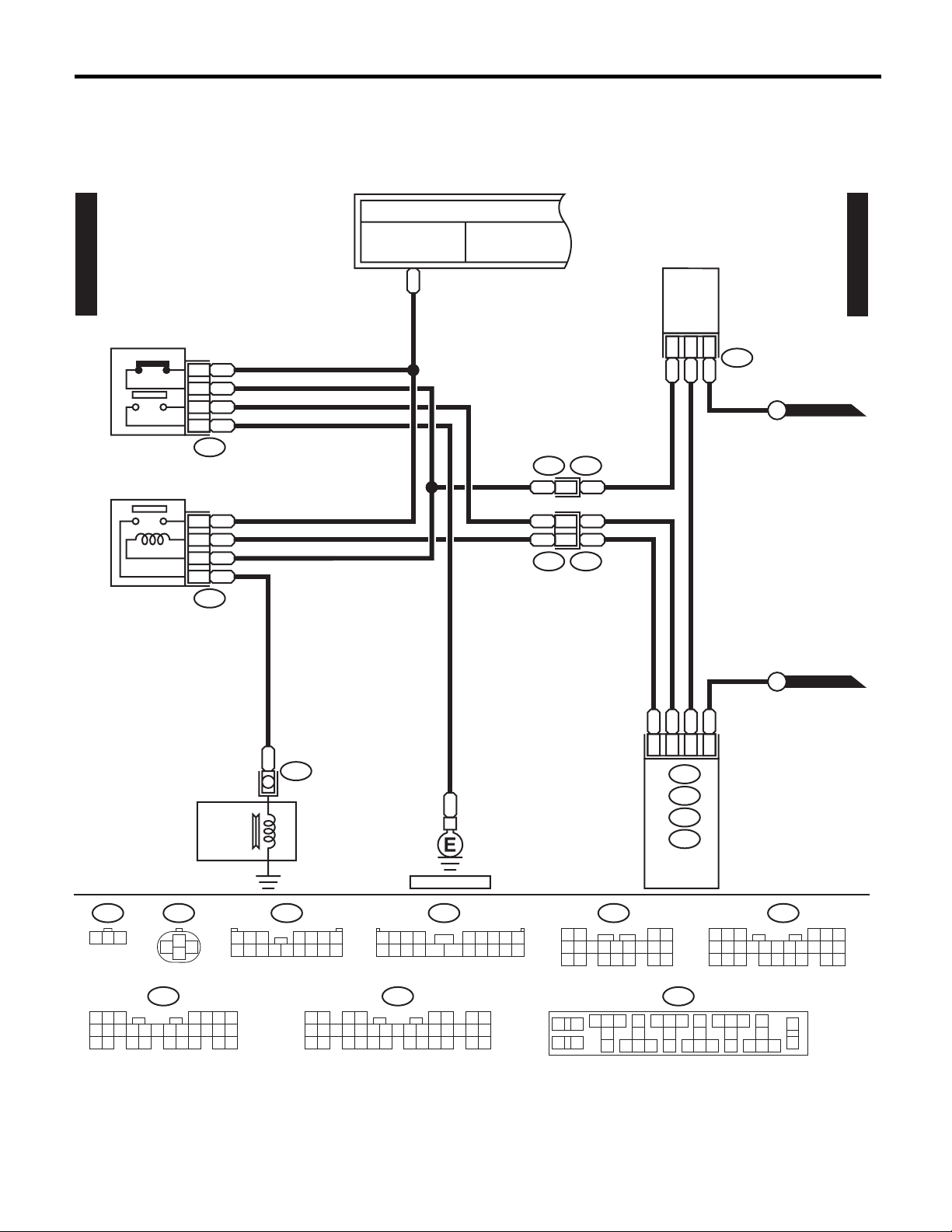
AIR CONDITIONING SYSTEM
6. Air Conditioning System
A: WIRING DIAGRAM
1. MANUAL A/C MODEL
F/B FUSE NO.17
A/C(M)-01
PRESSURE
SWITCH
GOr1
BrY
2
BrB4
B3
F79
AIR CONDITIONING
RELAY
TO POWER SUPPLY ROUTING
FB-17
(IG)
GOr
BrY
WIRING SYSTEM
EVAPORATION
THERMO SWITCH
A/C(M)-01
B256
LY 1
BW 2
BrY 3
A/C(M)-02
A
B62F45
BrY2
B256
1 2 3
GOr18
Br15
BrY
17
L19
F27
MAGNET
CLUTCH
COMPRESSOR
F79 F45
1
3
4
2
1 2 3
8 9
10 11 12 13 14 15 16
L
F24
4 5 6 7
B
REF. TO GND-01
(BLUE)
F2
1234 56789
10 11 12 13 14 15 16 17 18 19 20
BrB
Br 12
BrB3
Br
B100F2
A/C(M)-02
B
BrA9
LYC11
GBD13
BrBB11
B134
A:
B135
B:
B136
C:
B137
D:
ENGINE
CONTROL
MODULE
D:
B137
(GRAY)
41
6
7 8 9
5
14
32
10 11
12 13
17 19 20
1815 16
72198
18 19 20
10 11 12 13 14
(GRAY)
C:
B136
56
43
15 16 17
25 26
2321 22 24
B: A:
B135
567
8219
20 21
10
11 12 13 14 15
2422 23 25
43
16 17 18 19
26 27 28
(GRAY)(GRAY)
B134
1 2 3 4 5 6 7 8
9
10 11 12 13 14 15 16 17 18 19 20 21 22 23
24 25 26 27 28 29 30 31 32 33 34 35
WI-37
1 2
3 4
57
6
8
9
F27
15 1716
10
11
18
19
1312
14
RELAY HOLDER
(BLACK)
25 2726
20
21
24
2322
30
35
31
28
29
36
34
3332
WI-02995

WIRING SYSTEM
A/C(M)-02
A/C(M)-01
A/C(M)-01
GOr4
B
A
BL2
LgR1
B91
BY
AIR CONDITIONING SYSTEM
TO POWER SUPPLY ROUTING
FB-30
F/B FUSE NO.1(B)
F/B FUSE NO.2 (B)
RW
B10
GOr
B201
i40
B
GOr 4
REF. TO R/DEF-01
REF. TO ILLUMI-01
V3
B
B
GOr
9
10
R11
RL4
OrW2
FB-36
F/B FUSE NO.17
(IG)
GOr
BL17
BW18
LgR16
BL
BW
LgR
BL8
GB6
BW7
LgR1
i16
BY14
BY
GB10
GB
BR15
BR
YB11
YB
RW 2
GOr 1
GB 3
BR 4
BLOWER FAN MOTOR
BR
BG
BG 2
BR 3
YB 6
RY 4
BW 1
RY12
BW
B202
i41
RY
BW 13
BW
RY
YB
BR
GB
BY
BLOWER FAN
MOTOR RELAY
B50
2
1
B87
B86
BLOWER FAN RELAY
0 1 2 3 4
2
3
6
5
4
1
i15
A/C(M)-02
BLOWER FAN RESISTOR
FRESH/RECIRC
ACTUATOR
B87
1 2
3412 89
12 13 14 15 16 17 18 19 20 21 22 23 24
REF. TO GND-05
(BLACK)
B201
56 7
B50
12
34
10 11
REF. TO GND-05
B91
1
2 3 4
AIR CONDITIONING SWITCH
(BLACK)
B86
i15
123
4
65
WI-38
1 2
6 7 8 9
i16
3 4 5
10 11
B202
12
1234 56789
10 11 12 13 14 15 16 17 18 19 20
WI-02996

AIR CONDITIONING SYSTEM
2. AUTO A/C NON-TURBO MODEL
TO POWER SUPPLY ROUTING
FB-17
F/B FUSE NO.17
(IG)
FB-30
F/B FUSE NO.1(B)
F/B FUSE NO.2(B)
FB-8
M/B FUSE NO.2
(B)
FB-36
F/B FUSE NO.17
(IG)
WIRING SYSTEM
A/C(AN)-01
PRESSURE
SWITCH
AIR CONDITIONING
RELAY
GOr
RW
LR
GOr
A/C(AN)-01
BLOWER FAN
MOTOR RELAY
RW 2
GOr 1
GB 3
BR 4
B50
BLOWER FAN
MOTOR
GOr
1
BrY2
4
BrB
3
B
F79
18
GOr
Br15
BrY17
L19
F27
BrY
BrB
F45
Br 12
F2 B100
B62
BrY2
BrB3
Br
B10
LR21
GOr4
B201
BrA9
LYC11
GBD13
BrBB11
i40
LY
BrY
24
21GB18
G
RL
LgR
B202
12
22
13BL14
i41
BR 1
RL
BY 5
B87
GOr
BL 2
LgR 1
G3
B91
2
FRESH/RECIRC
ACTUATOR
4
MAGNET
CLUTCH
COMPRESSOR
B50
12
34
123456789
11 12 13 14 15 16 17 18 19 20
8219
20 21
B91
1 2 3 4
B:
i49
B:
B135
10
11 12 13 14 15
(GRAY)
2422 23 25
43
16 17 18 19
26 27 28
F79
1
3
2
10
567
L
F24
B
REF. TO GND-01
B87
1
2 3 4 5 6
4
3412 89
12 13 14 15 16 17 18 19 20 21 22 23 24
REF. TO GND-05
B201
56 7
1 2 3 4 5 6 7 8
9
10 11 12 13 14
24 25 26 27 28 29 30 31 32 333435
B
F45
1 2 3
8 9
10 11 12 13 14 15 16
(BLACK)
10 11
(GRAY)(GRAY)
A:
B134
15 16 17 18
A:
B134
B:
B135
B136C:
D:
B137
ENGINE
CONTROL
MODULE
4 5 6 7
12 13 14 15 16 17 18 19 20 21 22 23 24
19 202122 23
LRB4
A: (GRAY)
1 2 3 4 5 6 7 8
9
10 11 12 13 14 15 16
3412 89
567
1 2
3 4
GOrB5
A:
i48
B202
B
B11
i48
57
B:
6
8
9
LY
RL
GBB15
BrY
B17
B16
A10
AUTO A/C
CONTROL
i49
MODULE
D:
B137
6
7 8 9
5
14
10 11
F27
15 1716
10
11
18
19
1312
14
RELAY HOLDER
G
BLB18
LgR
B19
B20
32
10 11
12 13
17 19 20
1815 16
(BLACK)
25 2726
20
21
28
24
29
2322
BY
REF. TO GND-05
F2
41
1234 56789
10 11 12 13 14 15 16 17 18 19 20
C:
B136
10 11 12 13 14
72198
18 19 20
30
31
34
3332
2321 22 24
35
36
(GRAY)
43
56
15 16 17
25 26
WI-02997
WI-39

WIRING SYSTEM
AIR CONDITIONING SYSTEM
B13
WG
A/C(AN)-02
17 WG
WG
WG
B22
10
E3
WG
YB
22
YB
B3
RB
20 RB
RB
RB
23
RB
B:
A:
i48
A14
Or
Or19
Or
Or
B38
24
i3
Or
AUTO A/C CONTROL MODULE
i49
PB
B36
1
2 BR
i1
PB
BR
A1
A3
GY B6
i41
B202
B1
Y A7
V
R B14
RL
WR
GW B7
OrW A9
REF. TO R/DEF-01
REF. TO ILLUMI-01
AIR MIX ACTUATOR
WR 1
GW 2
Y4
GY 6
YB 3
i65
IN VEHICLE
TEMPERATURE SENSOR
YB 1
RW 2
i55
PB
BR
B62
15
14
F45
PB
BR
A/C(AN)-02
B2
A5
GY A4
GY
6
GY
RY A13
RY RY9
LW
8
LW LW
L A12
L L7
RW B12
Br
YB A16
Br Br5
YB YB15
W B9
YR B8
W10
W
YR YR11
SUNLOAD
SENSOR
B256
1
2
3
(GRAY)
YB
1
WG
3
THERMO METER
F78
i51
i55
1 2
B:
i49
123456789
11 12 13 14 15 16 17 18 19 20
RB
i51E8
2
10
CUSTOM
CPU
COMBINATION METER
(LIGHT GRAY) (BLACK)(BLACK)
E8
12
3
(LIGHT GRAY)
B22
1
2
3 4
5 6 7 8
9
10 11 12
13 14 15 16
17 18 19 20
Or
B30
I/F
12 13 14 15 16 17 18 19 20 21 22 23 24
PB
BRB24
B25
I/F
i65
12
3456
B36
B202
3412 89
567
B:
i10
123456789
W
RY
YR2
GY5
8
1
MODE ACTUATOR
B77
1 2 3 4 5 6 7 8 9
15 16 17 18 19 20 21 22 23 24 25 26 27 28 29 30
10 11
LW7L6LW4
(BROWN)
L9
YB
B77
10
10
1 2 3 4 5 6 7 8
9
B:
i10
PB
BR
1
2
AMBIENT
SENSOR
A:
(GRAY)
i48
10 11 12 13 14 15 16
(GREEN)
10 11 12 13 14
F78
EVAPORATION
THERMO SWITCH
1 2 3
8 9
1234 56
10 11 12 13 14 15716
23 30
22 26 27 28 29
24 31
25
Br
YB
B256
3
1
F45
5 6 7
4
10 11 12 13 14 15 16
B38
8
19 20
17
18
WI-02998
9
21
32
WI-40
 Loading...