

Subaru EX13 User Manual

SERVICE
MANUAL
Models
EX13,17,21,27
SP170,SP210
EX21 Electronic Fuel Injection
ENGINES
PUB-ES1934
Rev. 08/09

Robin America, Inc.
905 Telser Road • Lake Zurich, IL 60047 • Phone: 847-540-7300 • Fax: 847-438-5012
e-mail: sales@robinamerica.com • www.subarupower.com
© Copyright 2009 Robin America, Inc.

CONTENTS
Section Title Page
1. SPECIFICATIONS ...................................................................................................... 1
2. PERFORMANCE ...................................................................................................... 2
3. FEATURES ...............................................................................................................7
4. GENERAL DESCRIPTION OF ENGINE COMPONENTS........................................ 8
5. DISASSEMBLY AND REASSEMBLY .................................................................... 14
5-1 PREPARATIONS AND PRECAUTIONS............................................................14
5-2 SPECIAL TOOLS .............................................................................................. 14
5-3 DISASSEMBLY PROCEDURE.......................................................................... 15
5-4 REASSEMBLY PROCEDURE........................................................................... 29
6. ENGINE OIL ...........................................................................................................47
7. MAGNETO .............................................................................................................. 48
8. WIRING DIAGRAM................................................................................................. 51
9. ELECTRIC STARTER............................................................................................. 53
10. OIL SENSOR .......................................................................................................... 55
11. AUTOMATIC DECOMPRESSION SYSTEM........................................................... 56
12. CARBURETOR....................................................................................................... 57
13. RECOIL STAR TER................................................................................................. 61
14. INSTALLATION ...................................................................................................... 66
15. TROUBLESHOOTING............................................................................................ 68
16. STANDARD REPAIR TABLES ............................................................................... 74
15-1 STANDARD DIMENSIONS AND LIMITS OF USE ........................................... 74
15-2 TIGHTENING TORQUE .................................................................................... 80
17. MAINTENANCE AND STORAGE ..........................................................................81

1. SPECIFICATIONS
)
Model EX13D EX17D EX21D EX27D
Type
Bore & Stroke
Piston Displacement
Compression Ratio 8.5 8.3
Continuous Output kW(HP)/r.p.m.
Maximum Output kW(HP)/r.p.m. 3.2(4.3)/4000 4.2(5.7)/4000 5.1(7.0)/4000 6.6(9.0)/4000
Maximum Torque
Direction of Rotation Counterclockwise as viewed from the P.T.O.shaft side
Valve Arrangement Overhead cam system
Cooling System Forced air cooling system
Lubrication System Splash lubrication system
Lubricant
mm
(in.)
ml
(cu.in.)
N・m/r.p.m.
(kgf・m/r.p.m.)
(ft・lb./ r.p.m.)
58 x 48
(2.28 x 1.89)
126
(7.69)
1.9(2.6)/3000
2.2(3.0)/3600
8.1/2500
(0.83/2500)
(6.01/2500)
Automobile engine oil ;Grade SE or higher (SG,SH or SJ in recomended)
SAE 10W -30-----Under ordinary atmospheric temperatures
SAE 5W-30-------In cold areas
Air-Cooled, 4-Cycle, Slant Singl e-Cyl inder,
Horizontal P.T.O.Shaft, OHC Gasoline Engine
67 x 48
(2.64 x 1.89)
169
(10.31)
2.6(3.5)/3000
2.9(4.0)/3600
11.3/2500
(1.15/2500)
(8.34/2500
67 x 60
(2.64 x 2.36)
211
(12.87)
3.2(4.4)/3000
3.7(5.0)/3600
13.9/2500
(1.41/2500)
(10.26/2500
75 x 60
(2.95 x 2.36)
265
(16.17)
4.4(6.0)/3000
5.1(7.0)/3600
18.6/2500
(1.9/2500)
(13.74/2500
Capacity of Lubricant L 0.6 1.0
Carburetor Horizontal draft, Float type
Fuel Automobile unleaded gasol ine
Fuel C onsumption Rate
Fuel Supply System Gravity type
Fuel Tank Capacity L 2.7 3.6 6.1
Ignition System Transistorized magneto
Spark Plug NGK BR-6HS (CHAMPION RL86C)
Charging Capaci ty
(Option)
Starting System Recoil starter Recoil starter / Electric starter (Option)
Governor System Centrifugal flyweight system
Dry Weight
Dimensions (L x W x H)
*Specifications are subject to change without notice.
g/kW・h
(g/HP・h)
V-A ------------- 12-1 A , 3 A , 16.7 A (Opti on)
kg
(lb.)
mm
(in.)
(11.7x13.4x12.5)
14
(30.87)
297 x 341 x 318
367 (270) at continuous rated output
15
(33.08)
304 x 354 x 335
(12.0x13.9x13.2)
(12.2x14.4x13.2)
16
(35.28)
311 x 366 x 335
(46.31)
351 x 420 x 410
(13.8x16.5x16.1
21
- 1 -

2. PERFORMANCE
2-1 MAXIMUM OUTPUT
The Maximum output is the output of an engine with its throttle valve fully opened and considering that all the
moving parts are properly broken in.
A new engine may not produce full maxim um output while its moving parts are still not broken-in.
NOTE :
Pow er curves shown in the follo wing charts are made in conformity with SAE internal combustion engine standard
test code J1349.
2-2 CONTINUOUS RATED OUTPUT
The continuous rated output is the output of an engine at optimum gov erned speed which is most fav orable from
the view point of engin’ s life and fuel consumption.
When the engine is installed on a certain equipment, it is recommended that the continuous output required
from the equipment to be kept below this continuous rated output.
2-3 MAXIMUM TORQUE
The maximum torque is the torque at the output shaft when the engine is producing maximum output at a
specific r.p.m..
- 2 -

2-4 PERFORMANCE CURVES
EX13D
9.0
0.9
[HP]
5.0
4.0
3.0
kW
MAXIMUM TORQUE
4.0
3.5
MAXIMUM HORSEPOWER
3.0
2.5
8.0
7.0
0.8
0.7
TORQUE
OUTPUT
2.0
1.0
0
2.0
CONTINUOUS
RATED HP
1.5
RECOMMENDED
HORSEPOWER
RANGE
1.0
0.5
0
2000 2400 2800 3200 3600 4000
r.p.m.REVOLUTION
- 3 -

EX17D
12.0
1.2
[HP]
6.0
5.0
4.0
kW
4.5
4.0
3.5
3.0
2.5
MAXIMUM TORQUE
MAXIMUM HORSEPOWER
11.0
10.0
9.0
1.1
1.0
0.9
TORQUE
3.0
OUTPUT
2.0
1.0
0
CONTINUOUS
RATED HP
2.0
RECOMMENDED
HORSEPOWER
RANGE
1.5
1.0
0.5
0
2000 2400 2800 3200 3600 4000
r.p.m.REVOLUTION
- 4 -

[PS]
kW
5.5
EX21D
MAXIMUM TORQUE
15.0
14.0
13.0
12.0
1.5
1.4
1.3
1.2
7.0
6.0
5.0
4.0
3.0
OUTPUT
5.0
TORQUE
MAXIMUM HORSEPOWER
4.5
4.0
3.5
3.0
CONTINUOUS
RATED HP
2.5
RECOMMENDED
HORSEPOWER
RANGE
2.0
2.0
1.0
1.5
1.0
0.5
0
0
2000 2400 2800 3200 3600 4000
r.p.m.REVOLUTION
- 5 -

EX27D
[HP]
9.0
8.0
7.0
6.0
kW
MAXIMUM TORQUE
7.0
6.5
MAXIMUM HORSEPOWER
6.0
5.5
5.0
4.5
4.0
CONTINUOUS
RATED HP
19.0
18.0
17.0
16.0
15.0
1.9
1.8
1.7
1.6
1.5
TORQUE
5.0
4.0
OUTPUT
3.0
2.0
1.0
0
3.5
RECOMMENDED
3.0
2.5
2.0
1.5
1.0
0.5
0
2000 2400 2800 3200 3600 4000
HORSEPOWER
RANGE
r.p.m.REVOLUTION
- 6 -

3. FEATURES
3-1 EXTREMELY SILENT - SOFT TONE QUALITY
EX engines are 2dBA quieter and softer in tone than other engines in the same class.
This quiet and soft tone is achieved b y:
- A reduction in mechanical noise realized by emplo ying sophisticated OHC system.
- Employment of an optimized capacity Rigid Muffler.
3-2 EXTREMELY EASY START - NO KICK-BACK
Reliable Starting and Less Pulling Force are achieved by:
- Sophisticated Mechanical Compression Release System as well as newly designed Combustion Chamber.
- EX engines start instantly even at minus (-) 10°C, without any perceptible kick-back.
3-3 EXTREMELY EASY MAINTENANCE
Extreme ease of maintenance is realized by:
- High Parts Commonality
simplifies maintenance & lowers repair cost due to fe w er parts for service.
More than 90% of component parts are in common between more than two models, in such as Muffler,
Intake and Exhaust Valves, Valve Springs, etc.
Furthermore, more than 50% of component parts are in common among EX13, EX17 and EX21, in
such as Chain Guide, Air Cleaner, Ignition Coil, etc.
- Only with ordinary tools, routine maintenance, assembly and disassembly can be performed.
3-4 EXTREMELY ADVANCED TECHNOLOGY
Extreme reliability and durability are achieved b y:
- Heavy Duty Chain Driven OHC System
Oval type case-hardened steel links enhance performance and resist stretching, which result in extended
maintenance free operation.
- Completely New Main Bearing Cover’s Design
Flush-mounted main bearing cover with lower moment of def ormation significantly increases reliability and
engine life.
- Superior Cooling and Lubrication System
Heat reduction is achieved b y more efficient, larger and more numerous cooling fins on cr ankcase, cylinder
and mounting base, as well as by outstanding oil delivery system.
- Large Ball Bearings on both ends of crankshaft for maxim um stability under demanding loads .
- Cast Iron Cylinder Liner resists wear
3-5 EXTREME POWER AND PERFORMANCE
Extremely Higher Po wer and Lo wer Fuel Consumption are realiz ed b y :
- High speed and homogeneous combustion achiev ed by sophisticated Pentroof Combustion Chamber which
includes Intake and Exhaust Valves located at optimum angle.
- Straight Intake Port with minimal air flow resistance.
Environmentall y friendly
EX engines comply with EPA Phase 2 and CARB Tier II Emission Regulations in the USA.
Extreme application compatibility
With four versatile models, existing slant-cylinder engines can be easily replaced.
- 7 -
4. GENERAL DESCRIPTION OF ENGINE COMPONENTS
4-1 CYLINDER AND CRANKCASE
The cylinder and crankcase are aluminum die-casting
as a single piece. A special cast iron cylinder liner is
molded into the aluminum die-casting.
The crankcase has a mounting surface on the output
shaft side to which the main bearing cover is attached.
The cylinder is inclined to the right at an angle of 25
degrees from the horizontal as viewed from the output
shaft side.
Fig. 4-1
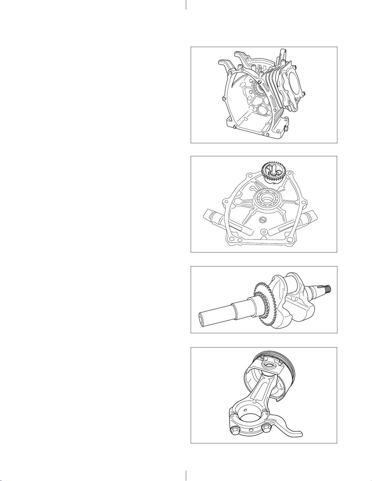
4-2 MAIN BEARING COVER
The main bearing cover is an aluminum die-casting,
which is mounted on the output shaft side of the
crankcase. By removing the main bearing cover, the
inside of the engine can be inspected with ease. Pilots
and bosses are machined into the cover to f acilitate the
direct coupling of the engine with machines such as
generators and pumps. There is an oil filling port, with
oil gauge, on either side of the cover.
4-3 CRANKSHAFT
The crankshaft is made of spheroidal graphite cast iron,
and the crank pin is high-frequency induction-hardened.
The crank sprocket used to drive the chain and the
gear used to drive the governor gear are pressed into
the output end of the shaft.
4-4 CONNECTING ROD AND PISTON
The connecting rod is a specially heat-treated aluminum
alloy die-casting. Its large and small ends function as
bearings. A splasher built into the connecting rod
lubricates by splashing engine oil. The piston is an
aluminum alloy casting with groov es for mounting two
compression rings and one oil ring.
Fig. 4-2
Fig. 4-3
- 8 -
Fig. 4-4

4-5 PISTON RINGS
The piston rings are made of special cast iron. The profile of the top ring is a barrel face or tapered face, and
that of the second ring is a tapered face. There are 2 types of oil ring depending on the engine specification.
As those are interchangeable, the cutter ring with coil expander type can be selected as the spare part.
BARREL
1
2
TOP
1
RING
(EX13/27)
TAPER
(EX17/21)
3
Fig. 4-5
4-6 CAMSHAFT
The camshaft and the sprocket are made of special
sintered alloy. They are constructed as a single piece.
The camshaft is provided with intake and exhaust cam,
and the decompression release lever is mounted on
the sprocket shaft end side.
4-7 VALVE ARRANGEMENT
2
3
SECOND
RING
OIL
RING
TAPER
CUTTER RING
WITH COIL
EXPANDER
THREE-PIECE
CONSTRUCTION
Fig. 4-6
EXHAUST VALVE INTAKE VALVE
This engine has a chain-driven overhead cam and
overhead valve construction, with a single cam
performing both intake and exhaust oper ations.
4-8 CYLINDER HEAD
The cylinder head is an aluminum die-casting with a
pent roof combustion chamber construction. The intak e
and exhaust ports are arranged in a cross direction to
improve combustion efficiency.
Fig. 4-7
Fig. 4-8
- 9 -

4-9 GOVERNOR SYSTEM
R
GOVERNOR GEAR
This engine is equipped with a centrifugal flyweight type
governor that makes it possible to oper ate the engine
at a constant speed, even with load variations. (The
governor flyweights are mounted on a governor gear .)
Fig. 4-9
4-10 COOLING SYSTEM
The engine uses a forced air-cooling system in which a cooling fan (which also works as a flywheel) forces
cooling air into the cylinder and the cylinder head. Baffles are provided to guide the flow of the cooling air.
(Model EX21 is provided with a synthetic resin cooling fan that is separate from the flywheel.)
4-11 LUBRICATION SYSTEM
The rotating parts, sliding parts and valv es of the engine
are lubricated with oil in the crankcase. The oil is splashed
onto the parts by the oil splasher on the connecting rod.
4-12 TIMING CHAIN
Timing chain system is adopted and designed for
lubricating for the upper portion of cylinder head.
The timing chain is engaged between the sprocket
portion of integrated camshaft in the cylinder head and
the crankshaft gear sprocket.
The sprocket teeth in particular shape are adopted to
enhance the durability and to realize low noise level.
4-13 IGNITION SYSTEM
The ignition system is a transistor controlled magneto
system with the ignition timing set at 23 degrees (EX13/
17/21)[27 degrees (EX27)] before the top dead center .
The magneto consists of a flywheel and ignition coil.
The flywheel (which also works as a fan) is directly
mounted on the crankshaft and the ignition coil is
directly mounted on the crankcase.
TIMING CHAIN
OIL SPLASHE
Fig. 4-10
※Model EX13,17,21 and 27D has a smooth advanced
ignition timing system to improve starting performance.
(For further details, refer to page 48, section
“7. MAGNET O”.)
-
10
IGNITION COIL
FLYWHEEL
Fig. 4-11
-

4-14 CARBURETOR
The engine is equipped with a horizontal draft
carburetor. The carburetor setting is calibrated after
careful testing for optimum all-round performance
(including starting, acceleration, fuel consumption,
output power characteristics). Special attention is also
paid to the general-purpose use of the engine. (For
further information, refer to page 57, section “11.
CARBURETOR”.)
Fig.4-12
4-15 AIR CLEANER
The engine uses an air cleaner that is quieter than
conventional ones. A semi-wet urethane foam element
is used in the STD air cleaner. Dual element air cleaner
(with a primary element of d ry type sponge and
secondary element of dry type paper) and other types
are also provided as special options.
4-16 BALANCER
(PROVIDED ONLY IN MODEL EX27D)
Unbalanced inertia force is cancelled by the balancer
which rotates at the same speed as the crankshaft to
effectively reduce vibration.
STD Type Dual Element Type
CLEANER
COVER
URETHANE
FOAM
Fig.4-13
CLEANER
COVER
URETHANE
FOAM
PAPER
ELEMENT
4-17 DECOMPRESSION SYSTEM
The automatic decompression system is mounted on
the camshaft. It opens the exhaust valve before the
compression top, thereby alle viating the compression
pressure and reducing the force required to pull the
recoil starter.
During engine operation, the decompression system is
overpowered by centrifugal force and compression is
fully utilized to produce power .
Fig.4-14
RETURN SPRING
ROCKER ARM
(EXHAUST VALVE SIDE)
EXHAUST
VALVE
CAMSHAFT
Fig.4-15
-
11
-

4-18 SECTIONAL VIEW OF THE ENGINE
Cross sectional view – across the shaft
FUEL TANK
TANK CAP
GOVERNOR SHAFT
BLOWER HOUSING
STARTING PULLEY
RECOIL STARTER
FLYWHEEL CHARGE COIL
(OPTION)
OIL SENSOR
(OPTION)
GOVERNOR LEVER
GOVERNOR GEAR
CRANKSHAFT
CONNECTING ROD
MAIN BEARING COVER
Fig. 4-16
-
12
-

M
S
G
G
N
R
Cross sectional view – along the shaft
FUEL STRAINER
CHAIN GUIDEGOVERNOR LEVER
FUEL TANK
OVERNOR
EAR
AGNETIC
WITCH
TIMING
CHAIN
STARTING
MOTOR
(OPTION)
MUFFLER COVER
EXHAUST
VALVE
MUFFLERPISTON
TAIL SCREE
or DEFLECTO
(OPTION)
SPARK
ARRESTER
(OPTION)
ROCKER
ARM
CAMSHAFT
INTAKE VALVE
PISTON PIN
PISTON RING
TENSIONER
OIL GAUGE
OIL DRAIN PLUG
FILLER PLUG
CONNECTING ROD
CRANKSHAFTCRANKCASE
OIL SENSOR
(OPTION)
Fig. 4-17
-
13
-

5. DISASSEMBLY AND REASSEMBLY
5-1 PREPARATIONS AND PRECAUTIONS
(1) When disassembling the engine, memorize the location of each part so that you can reassemble the engine
correctly. If necessary, attach identification tags with the required assembly information to the parts.
(2) Store groups of parts in separate boxes. This will make reassembly easier.
(3) To prevent parts from being mislaid, keep each group provisionally assembled after removing the parts from
the engine.
(4) Handle the disassembled parts with the utmost care. Clean them with cleaning oil if necessary.
(5) Use the correct tools in the correct way when disassembling and reassembling the engine.
5-2 SPECIAL TOOLS
Tool name Use
Commercially available product
Flywheel puller For pulling off the flywheel
FLYWHEEL PULLER
Fig. 5-1
-
14
-

5-3 DISASSEMBLY PROCEDURE
Step Parts to remove Remarks and procedures Fasteners
1 Drain the engine oill (1) Remove a drain plug (M14×12mm)
located on both sides of the case.
Take care not to lose the gaskets.
(2) To discharge oil quickly, remove the oil
guage.
14 mm spanner
OIL GAUGE
GASKET
STEP 1
GASKET
DRAIN PLUG
Fig. 5-2
-
15
-

Step Parts to remove Remarks and procedures Fasteners
Air cleaner cover Remove the air cleaner cover.
2
Air cleaner Remove the element, and remove the air
3
cleaner while pulling the breather pipe away
from the rocker cover.
STEP 3
AIR CLEANER COVER
URETHANE FOAM
10 mm box spanner
M6 nut: 2 pcs.
M6×20:1pc.
DUAL ELEMENT TYPESTD TYPE
STEP 3
AIR CLEANER
COVER
URETHAN FOAM
PAPER
ELEMENT
M6 x 20
FLANGE BOLT : 1 pc.
Fig. 5-3
-
16
AIR CLEANER COVER
STEP 2
BREATHER
PIPE
M6 FLANGE
NUT : 2 pcs.
-

Step Parts to remove Remarks and procedures Fasteners
Stop switch Disconnect the wire and remove the stop
4
switch from the blower housing.
Recoil starter Remove the recoil starter from the blower
5
Blower housing
Baffle 2 (head)
Baffle 3
housing.
(1)Remove the blower housing from the
crankcase.
(2)Remove the baffle 2 (head) and baffle 3.
6
STEP 4
M6 x 12 BOLT : 4 pcs.
M4 TAPPING SCREW : 2 pcs.
STOP SWITCH
10 mm box spanner
M6 × 8mm : 4 pcs.
10 mm box spanner
M6 × 12mm : 4 pcs.
10 mm box spanner or
spanner
M6 × 12mm : 2 pcs.
(Baffle 2 (head))
M5 tapping bolt : 2 pcs.
(Baffle 3)
M6 x 8 BOLT : 4 pcs.
STEP 5
BAFFLE 3
(EX21 ONLY)
M5 TAPPING BOLT : 2 pcs.
RECOIL STARTER
BLOWER HOUSING
STEP 6
BAFFLE 2 (HEAD)
M6 x 12 BOLT : 1 pc.
STEP 6
Fig. 5-4
-
17
-

Step Parts to remove Remarks and procedures Fasteners
Fuel tank (1) Drain fuel from the carburetor drain.
(2) Remove the fuel tank mounting nuts
and bolts from the crankcase.
(3) Disconnect the fuel pipe from the carburetor.
7
(See Fig. 5-6)
(4) Remove the fuel tank from the crankcase.
Muffler and Muffler cover (1) Remove the muffler cover from the
muffler.
(2) Remove the muffler from the cylinder
head. Take care not to lose the gasket.
8
※Take care not to cut your hand with the
muffler gasket.
※Seal the exhaust port with adhesive
tape or plug it with cloth to prevent nuts
and other objects from falling inside.
STEP 7
FUEL TANK
10 (12) mm spanner or box
wrench
M6 nut : 2 pcs.
(Models EX13, 17 and 21)
M8 nut : 2 pcs. (Model EX 27)
M6 × 25mm : 1 pc.
(Models EX 13, 17 and 21)
M8 × 25mm : 2 pcs.
(Model EX27)
12mm box spanner
10mm box spanner or
spanner
M6 tapping bolt : 2 pcs.
M6 × 8mm : 1 pc.
M8 nut : 2 pcs.
M8 × 12mm : 1 pc.
M6 x 10
TAPPING BOLT : 2 pcs.
STEP 8
M6 NUT : 2 pcs.
(EX13,17,21)
M8 NUT : 2 pcs.
(EX27)
FUEL PIPE
M6 x 8
FLANGE BOLT : 1 pc.
M8 NUT : 2 pcs.
M6 x 25 BOLT : 1 pc.
(EX13, 17, 21)
M8 x 25 BOLT : 2 pcs.
A
(EX27)
MUFFLER
M8 x 12
BOLT : 1 pc.
GASKET
(It has two faces)
FUEL DRAIN
Seal the exhaust port with
adhesive tape or plug it with cloth.
A
Fig.5-6
Fig.5-5
-
18
-

Step Parts to remove
Remarks and procedures
Fasteners
Governor system (1) Loosen the bolt and remove the governor
lever from the governor shaft. There is no
9
need to remove the bolt.
(2) Remove the governor spring.
(3) Remove the governor rod and the rod
spring from the carburetor.
Carburetor, Insulator Remove the carburetor from the cylinder head.
10
Speed control lever and
11
Bracket
STEP 9
GOVERNOR LEVER
Remove the insulator.
Remove the speed control lever and bracket
from the cylinder head.
GOVERNOR ROD
and ROD SPRING
GOVERNOR SPRING
10 mm box spanner or
spanner
M6 × 30mm : 1 pc.
10 mm box spanner
M6 × 12mm : 2 pcs.
GOVERNOR SHAFT
M6 x 12 BOLT : 2 pcs.
STEP 11
SPEED CONTROL LEVER
and BRACKET
GASKET
INSULATOR
GASKET
CARBURETOR
STEP 10
Fig.5-7
-
19
-

d
Step Parts to remove Remarks and procedues Fasteners
r
Ignition coil Remove the spark plug cap from the spark plug and
12
remove the ignition coil from the crankcase.
Starting pulley Remove the starting pulley from the flywheel.
Fit a box wrench or a socket wrench on the flywheel nut
and loosen the nut by knocking the wrench sharply with a
hammer. (See Fig. 5-10)
NOTE:
13
1) Do not insert a screwdriver or other objectbetween the
flywheel blades, otherwise the risk of damaging the
blades might be occured.
2) Knock the w rench with a hammer i n a counter
clockwise direction.
3) The fan of the Model EX21 engine is made of
synthetic resin. Take the utmost care when handling it.
Flywheel Remove the flywheel from the crankshaft. Leave the nut
temporarily to prevent the flywheel from dropping out.Fit
14
the flywheel puller as shown in Figure 5-11 and remove
the flywheel from the crankshaft by rotating the bolt at the
centerin a clockwise direction.
(Knock the center boltwit h a hammer sometimes)
10 mm box spanner
M6 × 25mm : 2 pcs.
19 (24) mm box spanner o
socket wrench M14 nut
(Models EX13,17 and 21)
M18 nut (Model EX27)
Flywheel pull er
FLYWHEEL PULLER
Fig. 5-10 Fig. 5-11
M14 NUT : 1 pc. (EX13,17,21)
M18 NUT : 1 pc. (EX27)
STEP 13
STEP 14
FLYWHEEL
STARTING
PULLEY
M6 x 25 BOLT an
WASHER : 2 pcs.
STEP 12
GROMMET
(EX13,17,21 only)
Fig. 5-9
ATTACH NUT
TEMPORARILY
-
20
-

.
.
Step Parts to remove Remarks and procedures Fasteners
Electric starter (option)
Control box,
Diode rectifier,
15
Magnetic switch
STEP 15
(1) Disconnect the grounding cable from battery.
(2) Disconnect the wire leading from the key
(3) Disconnect the wire that connects the
(4) Remove the electric starter.
ELECTRIC STARTER
(option)
switchSTterm inal to the magnetic switch.
positive terminal of the battery to the
magnetic switch.
M6 NUT : 1 pc. (EX17,21)
M8 NUT : 1 pc. (EX27)
EX27
M8 x 28 BOLT : 2 pcs.
EX17, 21
UPPER SIDE
M6 x 30 FLANGE BOLT : 1 pc
DOWN SIDE
M6 x 20 FLANGE BOLT : 1 pc
12 mm box spanner
M8 nuts
10 mm box spanner
12 mm box spanner
Fig. 5-8
-
21
-

Step Parts to remove Remarks and procedures Fasteners
Baffle 1 (case) Remove the baffle 1 (case) M6 × 12mm : 1 pc.
16
(Models EX13, 17 and 21)
M8 × 12mm : 1 pc.
(Model EX27)
Charge coil (option) Remove the charge coil.
17
(For EX27, remove the wire clamp together)
box spanner
M6 × 20mm : 2 pcs.
+ screwdriver
Spark plug Remove the spark plug from the cylinder head. 21 mm plug wrench
18
M6 x 12 FLANGE BOLT : 1 pc. (EX13, 17, 21)
M8 x 12 FLANGE BOLT : 1 pc. (EX27)
BAFFLE 1 (CASE)
For the model without electric starter.
A
STEP 16
STEP 17
CHARGE COIL
SPACER
Fig.5-12
STEP 18
SPARK PLUG
CHARGE COIL
VIEW
EX13
EX17
EX21
EX27
A
(EX27 only)
15W
40W
15W
40W
200W
15W
40W
200W
15W
40W
200W
CLAMP
SPACER
NA
NA
NA
NA
NA
BOLT
M6 x 40L
M6 x 35L
M6 x 35L
M6 x 40L
M6 x 25L
M6 x 35L
M6 x 40L
M6 x 25L
M6 x 20L
M6 x 30L
M6 x 25L
-
22
-

Step Parts to remove Remarks and procedures Fasteners
Rocker cover (1) Remove the rocker cover from the
19
cylinder head.
(2) Remove the gasket (rocker cover).
Rocker arm
20
Remove the pin (rocker arm) and the rocker
arm from the cylinder head at the compression
top dead center.(See Fig. 5-14b)
ROCKER ARM
(EXHAUST VALVE SIDE)
PIN
(ROCKER ARM)
ROCKER ARM (INTAKE VALVE SIDE)
10 mm box spanner
M6 × 12mm : 4 pcs.
The position of compression top dead center
Punch marks
Fig. 5-14a
STEP 20
ROCKER ARM
(INTAKE VALVE SIDE)
CLOSE-UP A
GASKET (ROCKER COVER)
A
Fig. 5-14b
ROCKER ARM
(EXHAUST
VALVE SIDE)
PIN
(ROCKER ARM)
STEP 19
Fig. 5-13
-
23
ROCKER COVER
M6 x 12 BOLT : 4 pcs.
-

Step Parts to remove Remarks and procedures Fasteners
Main bearing cover (1) Remove the flange bolts of main bearing
cover from the crankcase.
Remove the main bearing cover while
21
tapping gently around the cover using
a plastic hammer or similar tool.
(See Fig. 5-16)
Be careful not to damage the oil gauge
or oil seal or not to lose the pipe knocks.
12 mm box spanner
M8 × 35mm : 6 pcs.
(Models EX13, 17 and 21)
M8 × 35mm : 7 pcs.
(Model EX27)
Fig. 5-16
M8 x 35mm : 6 pcs.
(MODELS EX13,
17 AND 21)
M8 x 35mm : 7 pcs.
(MODEL EX27)
STEP 21
MAIN BEARING COVER
PIPE KNOCK
Fig. 5-15
-
24
-

Step Parts to remove Remarks and procedures Fasteners
22
Tensioner, Camshaft (1) Remove the tensioner. (See Fig. 5-18a)
※Do not lose the pin (tensioner).
(2) Remove the retaining bolt of pin (camshaft)
fromthe cylinder head.(See Fi g. 5-18b)
(3) Remove the pin (camshaft), taking care not
to scratch the O-ring.
(4) Remove the chain from the camshaft
sprocket and then take out the camshaft.
(See Fig. 5-19)
(5) Remove the chain from the crankshaft.
PIN (CAMSHAFT)
M6 x 12 BOLT : 1 pc.
Bolt used to prevent the
PIN (TENSIONER)
Fig.5-18a
pin (camshaft) from coming out
Fig.5-18b
M10 box spanner or spanner
M6 × 12mm : 1 pc.
Fig.5-19
CHAIN
SPRING
(TENSIONER)
PIN (TENSIONER)
CHAIN
CAMSHAFT
TENSIONER
STEP 22
PIN (CAMSHAFT)
Fig. 5-17
-
25
CAMSHAFT
STEP 22
M6 x 12 BOLT : 1 pc.
Bolt used to prevent the
pin (camshaft) from coming out
CHAIN
-

Step Parts to remove Remarks and procedures Fasteners
G
Cylinder head,
Chain guide
23
Intake and exhaust
valves
24
(1) Remove the cylinder head from the
crankcase.
(2) Remove the cylinder head gasket from the
cylinder head. Take care not to lose the
pipe knocks.
(3) Remove the chain guide from the top side
of the crankcase.
(If the chain guide is removed from the inner
side of the crankcase, it might be damaged.)
(1) Remove the collet valve from the
spring retainer. (See Fig. 5-21)
(2) Remove the intake valve and the exhaust
valve.
12 mm box spanner
M8 × 68mm : 4 pcs.
M8 × 35mm : 1 pc.
Fig.5-21
Push
PIPE KNOCK
INTAKE
VALVE
EXHAUST
VALVE
STEP 24
CHAINGUIDE
M8 x 35 BOLT : 1 pc.
(This bolt is same as the
main bearing cover bolt).
GASKET
SPRING RETAINER
VALVE SPRING
STEP 23
CYLINDER HEAD
COLLET VALVE
M8 x 68 BOLT : 4 pcs.
STEM SEAL
SPRING RETAINER
VALVE SPRIN
COLLET VALVE
Fig.5-20
-
26
-

Step Parts to remove Remarks and procedures Fasteners
Connecting rod and
piston
(1) Scrape off any carbon from the cylinder
and the piston head, then remove the
connecting rod bolt.
25
(2) Remove the connecting rod cap.
(3) Rotate the crankshaft until the piston
comes to its top position. Push the
connecting rod and remove the piston
from the upper part of the cylinder.
Piston and piston rings (1) Remove the piston clips (2 pcs.).T ak e
out the piston pin and then remove the
piston from the connecting rod small end,
taking care not to damage the connecting rod
26
small end.
(2) Remove the piston rings from the piston
by spreading them at the gap.
Take special care not to damage the rings
when doing this.
STEP 25
CONNECTING ROD CAP
CONNECTING ROD
10 mm box spanner
M6 × 33mm :2 pcs.
(Models EX13, 17 and 21)
M7 × 40mm : 2 pcs.
(Model EX27)
STEP 26
PISTON RING
CLIP
PISTON PIN
CLIP
M6 x 33 (EX13, 17, 21)
M7 x 40 (EX27)
CONNECTING ROD BOLT : 2 pcs.
Fig.5-22
-
27
-
PISTON
 Loading...