

Subaru EH36 User Manual


CONTENTS
Section
Title
Page
1
.
SPECIFICATIONS
.......................................................................................................
1
2
.
PERFORMANCE
........................................................................................................
3
2-1 MAXIMUM OUTPUT
........................................................................................................
3
2-2
CONTINUOUS RATED OUTPUT
....................................................................................
3
2-3 MAXIMUM TORQUE
.......................................................................................................
3
2-4 PERFORMANCE CURVES
.............................................................................................
4
3
.
FEATURES
..................................................................................................................
6
4
.
GENERAL DESCRIPTION OF ENGINE COMPONENTS
..........................................
7
4-1 CYLINDER AND CRANKCASE
.......................................................................................
7
4-2 MAIN BEARING COVER
.................................................................................................
7
4-3 CRANKSHAFT
..................................................................................................................
7
4-4 CONNECTING ROD AND PISTON
.................................................................................
8
4-5 PISTON
RINGS
...............................................................................................................
8
4-6 CAMSHAFT
.....................................................................................................................
8
4-7 VALVE ARRANGEMENT
.................................................................................................
9
4-8 CYLINDER HEAD
............................................................................................................
9
4-9 GOVERNOR SYSTEM
....................................................................................................
9
4-10 COOLING SYSTEM
.....................................................................................................
10
4-11 LUBRICATION SYSTEM
..............................................................................................
10
4-12 IGNITION SYSTEM
.....................................................................................................
10
4-13 CARBURETOR
.............................................................................................................
11
4-14 AIR CLEANER
..............................................................................................................
11
4-1
5
BALANCER
...................................................................................................................
11
4-16 DECOMPRESSION SYSTEM
.....................................................................................
12
4-17 SECTIONAL VIEW OF ENGINE
..................................................................................
13
5
.
DISASSEMBLY AND REASSEMBLY
.......................................................................
15
5-1 PREPARATIONS AND SUGGESTIONS
........................................................................
15
5-2 SPECIALTOOLS
...........................................................................................................
15
5-3
DISASSEMBLY PROCEDURES
....................................................................................
16
5-4 REASSEMBLY PROCEDURES
.....................................................................................
31
5-5
BREAK-IN OPERATION
................................................................................................
43
6 .
MAGNETO
................................................................................................................
43
6-1
OPERATION AND FUNCTION
......................................................................................
43
6-2
BASIC THEORY
............................................................................................................
43
6-3
WIRING DIAGRAM
........................................................................................................
45

Section
Title
Page
7 . AUTOMATIC DECOMPRESSION SYSTEM
............................................................
46
8
.
CARBURETOR
........................................................................................................
47
8-1
OPERATION AND CONSTRUCTION
............................................................................
47
8-2 DISASSEMBLY AND REASSEMBLY
.............................................................................
48
9
.
STARTING SYSTEM
................................................................................................
50
9-1 RECOIL STARTER
........................................................................................................
50
9-2 ELECTRIC STARTER
....................................................................................................
54
10
.
TROUBLESHOOTING
...........................................................................................
56
10-1 STARTING DIFFICULTIES
..........................................................................................
56
10-2 ENGINE MISFIRE
........................................................................................................
57
10-3 ENGINE
STOPS
..........................................................................................................
57
10-4 ENGINE OVERHEAT
...................................................................................................
58
10-5 ENGINE KNOCKS
.......................................................................................................
58
10-6 ENGINE BACKFIRES THROUGH CARBURETOR
.....................................................
58
11
.
INSTALLATION
.....................................................................................................
59
11-1 INSTALLING
.................................................................................................................
59
11-2 VENTILATION
..............................................................................................................
59
11 -3 EXHAUST GAS DISCHARGE
.....................................................................................
59
11 -4 POWER TRANSMISSION TO DRIVEN MACHINES
...................................................
59
12
.
SERVICE DATA
.......................................................................................................
60
12-1 CLEARANCE DATAAND LIMITS
................................................................................
60
12-2 TORQUE SPECIFICATIONS
.......................................................................................
66
12-3 OIL GRADE CHART
....................................................................................................
66
13
.
MAINTENANCE AND STORAGE
..........................................................................
67
13-1 DAILY MAINTENANCE
................................................................................................
67
13-2 INITIAL
20
HRS . MAINTENANCE
...............................................................................
67
13-3 EVERY
50
HRS
.
(10 DAYS) MAINTENANCE
.............................................................
67
13-4 EVERY
100-200
HRS . (MONTHLY) MAINTENANCE
.................................................
68
13-5 EVERY
500-600
HRS . MAINTENANCE
......................................................................
68
13-6 EVERY 100
HRS
.
(YEARLY) MAINTENANCE
............................................................
68
13-7 ENGINE STORAGE
...........................................
:
.........................................................
68
I
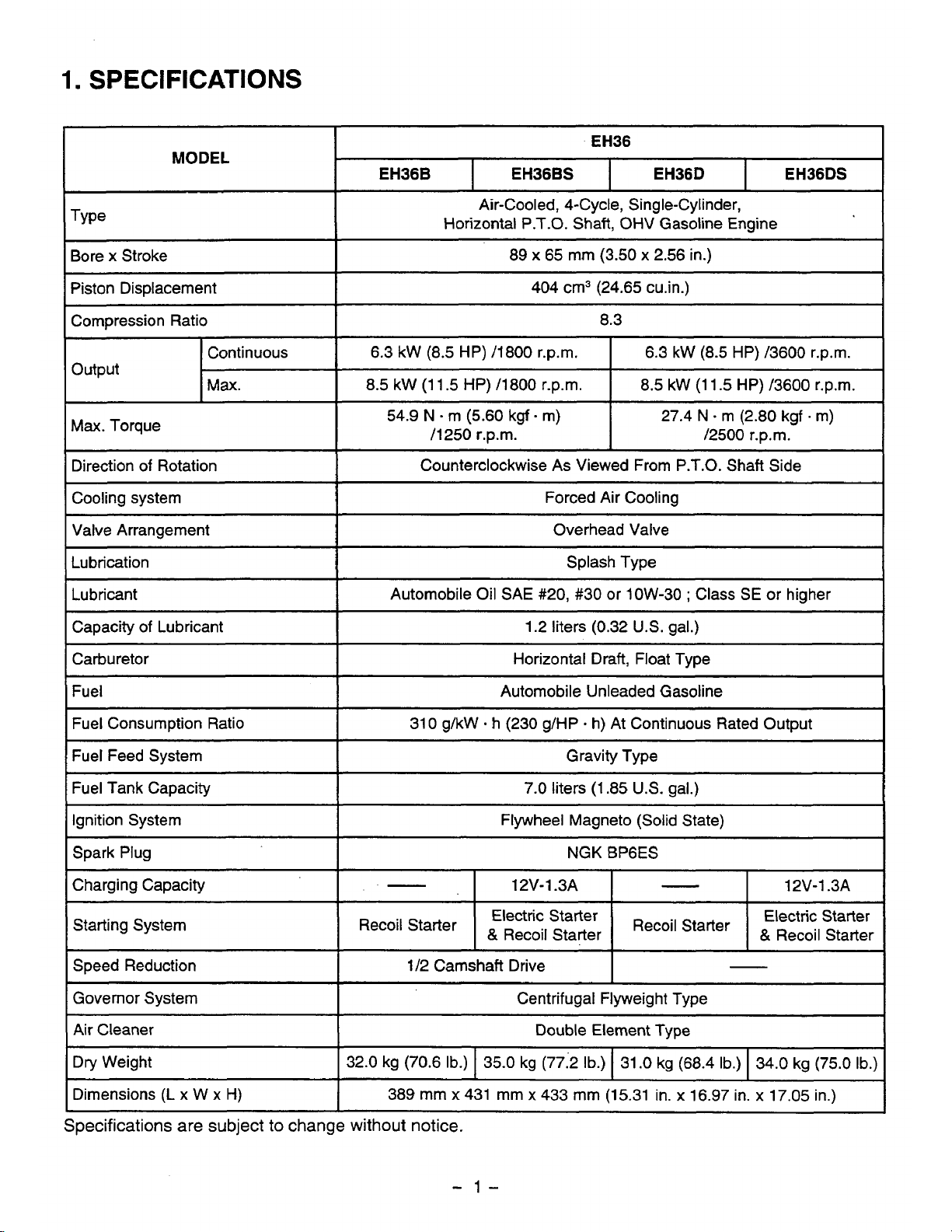
EH36
1
MODEL
~~~ ~ ~
EH36B
EH36DS EH36D
EH36BS
I
I
I
Type
Air-Cooled, 4-Cycle, Single-Cylinder,
Horizontal P.T.O. Shaft, OHV Gasoline Engine
Bore
x
Stroke
8.3
Compression Ratio
404 cm3 (24.65 cu.in.)
Piston Displacement
89
x
65 mm (3.50 x 2.56 in.)
Continuous
6.3
kW
(8.5 HP)
/3600
r.p.m. 6.3 kW (8.5
HP)
/I800
r.p.m.
output
Max.
8.5 kW (1 1.5
HP)
/3600 r.p.m.
8.5 kW
(1
1.5
HP)
/1800 r.p.m.
~
Max. Torque
54.9
N
-
m
(5.60
kgf
-
m)
/1250 r.p.m.
27.4
N
-
m (2.80 kgf m)
/2500
r.p.m.
I
Direction
of
Rotation
1
Counterclockwise As Viewed From P.T.O.
Shaft
Side
I
____~
Cooling system
Valve Arrangement
Forced Air Cooling
Automobile Oil SAE
#20,
#30 or 1OW-30 ; Class
SE
or higher
Lubricant
Splash Type Lubrication
Overhead Valve
~_____
Capacity of Lubricant 1.2 liters (0.32
U.S.
gal.)
Carburetor
I
Horizontal Draft, Float Type
Fuel
Fuel Tank Capacity
Gravity Type
Fuel Feed System
31
0
g/kW
-
h
(230 g/HP
-
h)
At Continuous Rated Output Fuel Consumption Ratio
Automobile Unleaded Gasoline
7.0 liters
(1.85
U.S.
gal.)
Ignition System
I
Flywheel Magneto (Solid State)
I
Spark Plug NGK BP6ES
Charging Capacity
-
-
1/2
Camshaft Drive
Speed Reduction
Starting System
12V-1.3A
-
1
2V-
1.3A
Governor System
Centrifugal Flyweight Type
Air Cleaner
Double Element Type
Recoil
Starter
&
Recoil Stafler
&
Recoil Starter
Recoil
Starter
Electric Starter
Electric Starter
Dry Weight
I
32.0 kg (70.6
Ib.)
I
35.0 kg (77:2 Ib.) I 31
.O
kg (68.4 Ib.) I 34.0 kg
(75.0
Ib.)]
~_____
Dimensions
(L
x W x
H)
389 mm x 431 mm x 433 mm (15.31
in.
x
16.97 in.
x
17.05
in.)
I
Specifications are subject
to
change
without
notice.
-
1-

EH41
I
MODEL
EH41 B
EH41
DS
EH41
D
EH41 BS
Air-Cooled, 4-Cycle, Single-Cylinder,
Horizontal P.T.O. Shaft, OHV Gasoline Engine
I
Bore x Stroke
89
x
65
mm
(3.50 x 2.56 in.)
btonbisplacement
404 cm3 (24.65 cu.in.)
1
Empression Ratio
~~
8.3
I
Continuous
7.0 kW
(9.5
HP) 13600 r.p.m.
7.0 kW
(9.5
HP) /1800 r.p.m.
Output
Max.
9.9
kW (13.5 HP) /3600 r.p.m.
9.9
kW (13.5 HP) /1800 r.p.m.
,
Max. Torque
56.8
N
m
(5.80 kgf - m)
I
28.4
N
-
m (2.90 kgf m)
/1250 r.p.m.
/2500
r.p.m.
Direction
of
Rotation
Cooling system
Counterclockwise
As
Viewed From P.T.O. Shaft Side
Splash Type
Lubrication
Overhead Valve
Valve Arrangement
Forced Air Cooling
(Lubricant
I
Automobile Oil
SAE
#20, #30 or low-30 ; Class
SE
or
higher
I
Capacity
of
Lubricant
310 g/kW
-
h (230 g/HP - h) At Continuous Rated Output
Fuel Consumption Ratio
Automobile Unleaded Gasoline
Fuel
Horizontal Draft, Float Type
Carburetor
1.2 liters (0.32
U.S.
gal.)
/
7
I
Fuel Feed System
T~-
Gravity Type
1
7.0 liters (1.85
US.
gal.)
Ignition System
Spark Plug
Flywheel Magneto (Solid State)
12V-1.3A 12V-1.3A
-
Charging Capacity
NGK
BPGES
Starting System
Speed Reduction
1/2 Camshaft Drive
-
Governor System
Centrifugal Flyweight Type
Air Cleaner
Double Element Type
Electric Starter
&
Recoil Starter
Recoil
Starter
&
Recoil Starter
Recoil
Starter
Electric Starter
Dry Weight
Dimensions
(L
x W x
H)
389 mm x 431 mm
x
433 mm (1 5.31 in. x 16.97 in. x 17.05 in.)
~ ~~
32.0 kg (70.6
Ib.)
34.0 kg
(75.0
Ib.)
31.0 kg (68.4
Ib.)
35.0 kg (77.2
Ib.)
Specifications
are
subject
to change without
notice.
/"
-
2-

2.
PERFORMANCE
2-1
MAXIMUM OUTPUT
The maximum output is the output of an engine with its throttle valve fully opened under the condition that
all
the moving parts are properly broken in after the initial break-in period.
A
new engine may not produce full maximum output while its moving parts are still not broken-in.
NOTE
:
Power curves shown in the following charts are made in conformity with
SAE
internal combustion engine
standard test code
J
1349.
2-2
CONTINUOUS
RATED
OUTPUT
The continuous rated output
is
the output of an engine at optimum governed speed which is most favor-
able from the view point of engine's life and fuel consumption.
When the engine is installed on a certain equipment, it is recommended that the continuous output
required from the engine be kept below this continuous rated output.
2-3
MAXIMUM TORQUE
The maximum torque is the torque at the output shaft when the engine is producing maximum output at
certain revolution.
-
3-

2-4
PERFORMANCE
CURVES
EH36
( )
for
type
B
t
kgf-m
(5.6) 2.8
(5.4) 2.7
(5.2) 2.6
!!j
(5.0) 2.5
(4.8) 2.4
(4.6)
2.3
(4.4) 2.2
HP
12
11
10
9
8
7
6
5
4
3
Nom
:54) 27
:52) 26
:50)
25
:48) 24
:46)
23
(44) 22
kW
9.0
8.0
7.0
6.0
5.0
4.0
3.0
2.0
24
(1 2)
28
(1
4)
32
(1
6)
36
(1
8)
REVOLUTION
r.p.m.
-
4-

EH41
kgfom
(5.8)
2.9
1
w
(5.6) 2.8
-
(5.2) 2.6
I-
HP
14
13
12
11
10
9
8
7
6
5
4
3
(
for
tvpe
B
Nom
(56)
28
(54)
27
(52)
26
kW
10.0
9.0
8.0
7.0
6.0
5.0
4.0
3.0
2.0
20
24 28 32 36
x10
’
(10)
(12) (14) (16) (18)
REVOLUTION
r.p.m.
-
5-

1.
The overhead valve design offers a compactness, light weight and ideal combustion characteristics
resulting in more power from less fuel and prolonged engine life.
2.
The adoption of an inclined cylinder offers low height
of
engine, making the arrangements for installing
the engine much easier for various powered equipments.
3.
The vibration, free design with a balancer system and lighter reciprocating parts.
4.
Combustion and mechanical noises have been analized acoustically and improved
for
better tonal
quality and lower engine noise.
5.
The automatic decompression system lightens the recoil pull force by
50%
comparing to the conven-
tional
SV
engine.
-
6-

4.
GENERAL DESCRIPTION
OF
ENGINE COMPONENTS
4-1
CYLINDER AND CRANKCASE
The cylinder and crankcase is a single piece alu-
minum die-casting.
The cylinder liner, made of special cast iron, is
molded into the aluminum casting.
The crankcase has a mounting surface on the out-
put shaft side, where the main bearing cover is
attached.
I
Fig.
4-
1
4-2
MAIN BEARING
COVER
The main bearing cover is an aluminum die-cast-
ing, which is mounted on the output shaft side of
the crankcase.
Remove the main bearing cover to inspect inside
of
the engine.
Pilots and bosses are machined
on
the cover for
direct mounting
of
the engine onto such machines
as generators and pumps.
Oil gauges (fillers) are on both sides of the cover
for easy maintenance.
I
OilGAUGE
-
Fig.
4-2
4-3
CRANKSHAFT
The crankshaft
is
forged carbon steel, and the
crank pin is induction-hardened.
The output end
of
the shaft has a crankshaft gear
and balancer gear that are pressed into position.
Fig.
4-3
-
7-
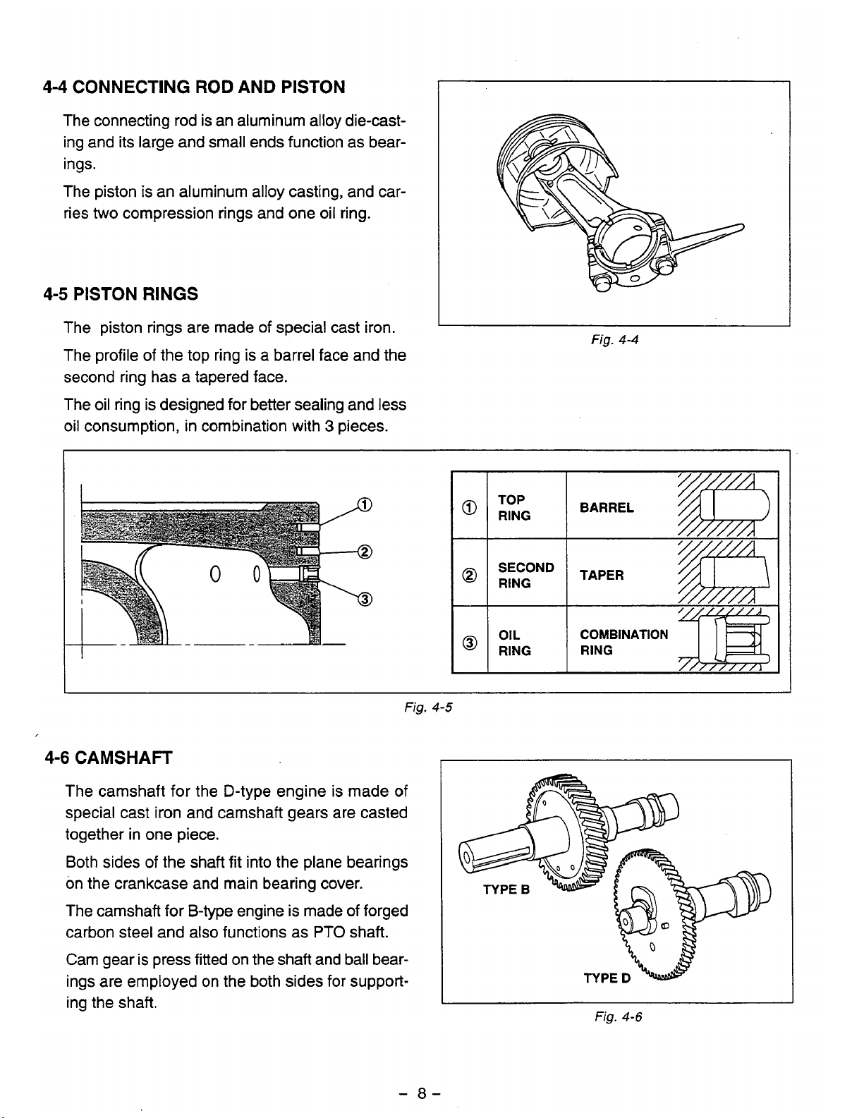
4-4
CONNECTING ROD AND
PISTON
The connecting rod is an aluminum alloy die-casting and its large and small ends function as bear-
ings.
The piston is an aluminum alloy casting, and car-
ries
two
compression rings and one oil ring.
4-5
PISTON
RINGS
The piston rings are made
of
special cast iron.
The profile of the top ring is a barrel face and the
second ring has a tapered face.
The oil ring is designed for better sealing and less
Fig.
4-4
oil consumption, in combination with 3 pieces.
TOP
BARREL
@
RING
TAPER
@
RING
OIL
COMBINATION
@
RING
RING
4-6
CAMSHAFT
The camshaft for the D-type engine is made of
special cast iron and camshaft gears are casted
together in one piece.
Both sides
of
the shaft fit into the plane bearings
on the crankcase and main bearing cover.
The camshaft for B-type engine is made of forged
carbon steel and also functions as
PTO
shaft.
Cam gear
is
press fitted on the shaft and ball bearings are employed on the both sides for supporting the shaft.
I
I
Fig.
4-5
Fig.
4-6
-
8-

The intake valve is located on flywheel side of the
cylinder head.
Hard alloy valve seats are molded in the cylinder
head and stellite is fused to the exhaust valve face.
The cylinder baffle leads cooling air to the exhaust
valve area for the optimum cooling.
EXHAUST VALVE INTAKE VALVE
Fig.
4-7
4-8
CYLINDER
HEAD
The cylinder head is an aluminum die-casting
which utilizes semi-spherical type combustion
chamber for the high combustion efficiency.
Fig.
4-8
4-9
GOVERNOR
SYSTEM
The governor is a centrifugal flyweight type which
ensures constant operation at the selected speed
against load variations.
The governor gear with governor weights is in-
stalled on the main bearing cover.
~
"
GOVERNOR
GEAR
/
Fig.
4-9
-
9-

4-10
COOLING
SYSTEM
The large fins on the flywheel provide sufficient
cooling air capacity for the inlet and exhaust area
and cylinder.
The cylinder baffle helps the cooling air flow effi-
ciently.
4-11
LUBRICATION
SYSTEM
All
the rotating and sliding parts are splash- lubri-
cated by the
oil
splasher on the connecting rod.
I
OIL
SPLASHER
4-12
IGNITION SYSTEM
The ignition system is a transistor controlled rnag-
net0 system which consists of a flywheel and an
ignition coil with a built-in transistor mounted
on
the crankcase.
This system has an automatic ignition timing advance characteristic for easy starting.
Fig.
4-
10
FLYWHEEL
I
Fig.
4-
11
P
-
10-
.

4-13 CARBURETOR
The engine is equipped with a horizontal draft car-
buretor that has a float controlled fuel system and
a
fixed main jet.
The carburetors are calibrated carefully for sure
starting, good acceleration, less fuel consumption
and sufficient output.
For
details, refer to page
47,
section
"8
CARBU-
RETOR''.
4-1 4 AIR CLEANER
Air-cleaner
ment system
(semi-wet) and secondary one
per element.
is
a heavy-duty type with a dual ele-
;
the primary one is an urethane foam
is
a dry type pa-
KNOB
&
Fig.
4-72
URETHANE
FOAM
4-15 BALANCER
Unbalanced inertia force is cancelled
ancer which rotates in the same speed as the
crankshaft to effectively reduce vibration.
by
the bal-
I
CLEANER
CASE
Fig.
Fig.
4-
13
4-14
ELEMENT
-
11
-

4-16
DECOMPRESSION
SYSTEM
AUTOMATIC
DECOMPRESSION
SYSTEM
An automatic decompression mechanism which
opens exhaust valve before the piston reaches
compression top
is
assembled
on
the
camshaft
for
easy starting.
RETURN SPRING
Fig.
4-
15'
-
12-

4-17
SECTIONAL VIEW
OF
ENGINE
MUFF
P.T.O.
MAIN
BEARING
COVER
Fig.
4-16
FLYWHEEL
-
13-

FUEL TANK SPARK PLUG
I
BALANCER SHAFT
\
CRANKSHAFT CRANKCASE
Fig.
4-17
CAMSHAFT
-
14-

5.
DISASSEMBLY AND REASSEMBLY
5-1
PREPARATIONS
1)
When disassembling the engine, memorize the locations
reassembled correctly.
attached
2)
Have boxes ready to keep disassembled parts by group.
3)
To
prevent losing and mispfacing, temporarily assemble each group
4)
Carefully handle disassembled parts, and clean them with washing oil
5)
Use the correct
SPECIAL TOOLS
5-2
to
Tool
them.
No.
AND
tools
SUGGESTIONS
If
you are uncertain
in the correct way.
of
of
identifying some parts, it
Tool
individual parts
is
suggested that tags be
of
disassembled parts.
if
necessary.
so
that they can be
Use
209-95004-07
FLYWHEEL
PULLER
with
bolt
For pulling
off
the flywheel Flywheel puller
-
15-

5-3
DISASSEMBLY
PROCEDURES
fi
Step
Fasteners
Remarks
and
procedures
Parts
to remove
Engine oil drain
(2)
To
discharge oil quickly, remove
(1)
Remove
oil drain plug
and
drain
1
oil.
oil gauge.
OIL LEVEL
GASKET
I
OIL
DRAIN
PLUG
GAUGE
Fig.
5-2
-
16-

Step
2
3
Parts
Air cleaner cover and elements
Air cleaner base and gasket
to remove
Remarks and procedures
Remove breather
head.
pipe
from
cylinder
v
Fasteners
cap
nut
M6
flange nut
2
pcs.
M6
x
28
:
1
CAP
:
pce.
NUT
fig.
-
17-
5-3

Step
4
Parts
to
remove
Fuel tank
.r
Stop
switch
M8
BOLT
AND
WASHER
ASSY
:
Remarks and procedures
(1)
Close fuel cock.
(2)
Loosen the
nut
of
fuel strainer
and
remove it.
(3)
Disconnect fuel pipe from
fuel
strainer.
*
Wipe
off
spilt
fuel thoroughly.
Disconnect wire complete.
Fasteners
M8 x 20
;
4
pcs.
Remove
stop switch.
I
screw
;
2
pcs.
RUBBER
PIPE
Fig.
5-4
-
18-

Parts to remove
Control
box,
Diode rectifier,
Magnetic switch
and
Electric
starter (Option)
Remarks and procedures
(1)
Disconnect wires
and
remove
(2)
Remove
black
wires from electric
(3)
Loosen
two
bolts and remove
control
box.
starter.
electric starter.
Fasteners
I
M8
;
2
pcs.
WIRE
2
M6
NU1
M6
FLANGE BOLT
:
1
me.
1
M6
SCREW
(PANHEAD)
:
1
pce.
Fig.
5-5
-
19-

Step
Fasteners
Remarks
and
procedures
Parts
to
remove
7
Muffler and muffler bracket Be careful not
to
lose muffler gasket.
M8
nut
;
2
pes.
M8
x
16
;
2
pcs.
Remove carburetor carefully
spring from governor lever.
8
unhooking governor rod and rod
Carburetor
M6
TAPPING
SCREW
:
5
DCS.
M8
FLANGE
FFLER
UNIT
A
Fig.
5-6
-
20-
 Loading...