

Page 1

Model 5330 Flex-Use
Dante® Audio Interface
User Guide
Issue 1, July 2018
This User Guide is applicable for serial numbers
M5330-02001 and later with application firmware 1.0 and later
and Dante firmware 4.2.0 (UltimoX4 4.1.2.1)
Also applicable for serial numbers
M5330-00151 to 02000 with application firmware 1.0 and later
and Dante firmware 2.5.0 (Ultimo 4.0.9.1)
Copyright © 2018 by Studio Technologies, Inc., all rights reserved
www.studio-tech.com
50602-0718, Issue 1
Page 2

This page intentionally left blank.
Page 3

Table of Contents
Revision History ................................................................... 4
Introduction ........................................................................... 5
Installation ............................................................................ 9
Configuration ........................................................................
Operation .............................................................................. 13
Technical Notes ....................................................................
Specifications .......................................................................
12
18
22
Model 5330 User Guide Issue 1, July 2018
Studio Technologies, Inc. Page 3
Page 4

Revision History
Issue 1, July 2018:
1. Initial release.
Issue 1, July 2018 Model 5330 User Guide
Page 4 Studio Technologies, Inc.
Page 5
Introduction
The Model 5330 Flex-Use Dante Audio Interface provides a simple yet high-performance
means of interfacing analog signals with
applications that utilize Dante® audio-overEthernet media networking technology. Four
line-level analog sources can be connected
to the unit and then, after conversion to digital, output by way of four output (transmitter)
channels associated with the Dante interface. Four signals that arrive by way of Dante
can be converted to analog and then output
as balanced line-level signals. A monitor section allows the input and output signals to be
selectively observed using meters, a headphone output, and a line-level output.
The Model 5330 is a fully professional product that offers the audio quality, features,
and reliability required by 24-hour commercial applications. Four inputs, two on the
front panel and two on the back, allow simple
interfacing with a variety of unbalanced
and balanced line-level analog sources. The
2-channel (stereo) input on the front panel
is optimized for use with portable electronics
that provide “–10” unbalanced audio sources.
Using a rotary control, users can adjust the
sensitivity of the input circuitry to match the
level of the source. Two additional inputs are
provided on the back panel and meet the
requirements of professional audio equipment. They are differential (balanced) with
a nominal level of +4 dBu and plenty of
signal-handling “headroom.” The four input
signals are converted to 24-bit digital audio
and then transported out of the unit via the
Dante interface.
Four digital audio channels enter the Model
5330 via its Dante interface. These generalpurpose audio channels are then converted
from the digital domain to the analog domain. Four 3-pin male XLR connectors,
located on the unit’s back panel, provide
balanced +4 dBu-nominal line-level analog
outputs. An auxiliary output, also located
on the back panel, provides a fifth “professional-quality” output. Pushbutton switches,
located on the front panel, allow the user
to select the source for the auxiliary output
from among the four Dante input (receiver)
channels.
The monitor section allows the user to
select any audio input or output signal
for visual and aural observation. Two
8-segment LEDs meters, calibrated in
dBFS, allow precise monitoring of signal
levels as they exist in the digital domain.
A 2-channel (stereo) headphone output
allows connection of headphones or ear
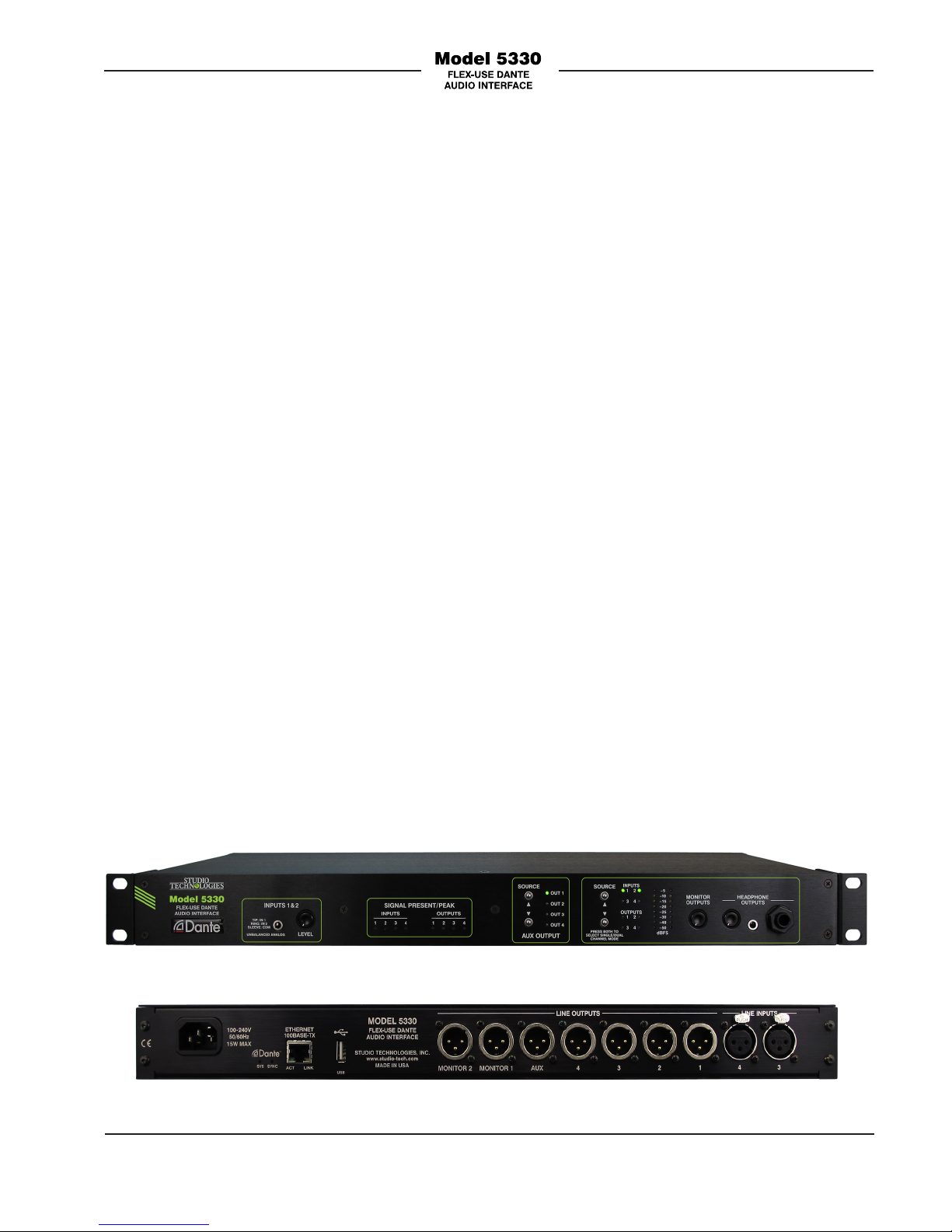
Figure 1. Model 5330 front view
Figure 2. Model 5330 back view
Model 5330 User Guide Issue 1, July 2018
Studio Technologies, Inc. Page 5
Page 6

buds that use either 3.5 mm or ¼-inch jacks.
A separate line-level analog monitor output
allows connection to inputs on amplified
speakers or power amplifiers. Two rotary
controls allow individual adjustment of the
headphone and monitor outputs.
An Ethernet connection is all that’s required
to make the Model 5330 part of a sophisticated networked audio system. Dante
audio-over-Ethernet has found wide
acceptance as an audio “backbone” due
to its ease of use, interoperability, excellent
audio quality, and wide adoption by a large
number of equipment manufacturers.
The Model 5330 can serve as an “edge”
device for a Dante network implementation,
providing high-performance input, output,
and monitor resources for various applications. The unit is an excellent general-purpose “tool” to help expand Dante capabilities
for facilities and applications that were initially implemented to support signals in the
analog domain.
A major benefit of using Dante is its abil
ity to use any standard Ethernet network
implementation, including cabling and
switches, to directly transport professional
audio signals. The Model 5330 supports
digital audio signals with sample rates of
44.1 and 48 kHz and a bit depth of up to
24. These sample rates were selected for
optimal support of broadcast, production,
industrial, commercial, and consumer applications. Status LEDs provide a real-time
indication of LAN and Dante performance.
The signals associated with the Model
5330’s four analog input channels are
converted to digital and then routed to
transmitter (output) channels on the unit’s
Dante interface. Four Dante transmitter (output) channels from an associated
Dante-enabled device can be assigned to
the Model 5330’s input (receiver) channels using the Dante Controller application.
These input signals are converted into analog and then sent to the output circuitry.
The Model 5330 is “universal” mains powered, requiring 100 to 240 volts, 50/60 Hz
for operation. Standard connectors are
used for interfacing with the audio input and
output channels, Ethernet interface, and AC
mains input. The unit’s enclosure mounts in
one space (1U) of a standard 19-inch rack
enclosure and weighs less than four pounds
(2 Kg).
Applications
The Model 5330 is a general-purpose
analog input, analog output and monitoring device intended for use in a variety of
audio and audio-with-picture applications
where Dante technology is utilized. It’s
applicable anywhere that line-level analog
inputs and outputs need to be converted to
and from Dante while audio quality is maintained. The term “Flex-Use” comes from
Dante Audio-over-Ethernet
Digital audio data associated with the Model
5330 is interfaced with a local area network
(LAN) using Dante audio-over-Ethernet
media networking technology. The unit is
compatible with the Dante Domain Manager™ (DDM) software application. For serial
numbers 02001 and later, the unit is also
the flexibility that the unit’s range of simple
but carefully-implemented resources can
provide. It’s suitable for demanding on-air
broadcast and live-event applications that
require both excellent audio performance
and reliable operation. It can also be a perfect complement for academic, industrial,
or corporate audio-visual facilities where a
compliant with AES67 digital audio signals.
Issue 1, July 2018 Model 5330 User Guide
Page 6 Studio Technologies, Inc.
Page 7

variety of analog input and output devices
must be supported.
The rack-mounted unit is appropriate for
installation in fixed locations, serving the
needs of systems associated with stadium,
worship, education, commercial, and government facilities. Its lightweight enclosure
also makes it suitable for mobile and field
uses. The Model 5330 features an optimized set of controls and indicators that
makes it simple and intuitive to use. With
the unit’s metering and monitoring resources it’s easy for users to obtain optimal
performance. And by providing standard
connectors for all inputs and outputs, along
with universal AC mains powering, installation and setup can be completed in only a
short period of time.
Four Analog Inputs
The Model 5330’s four inputs allow connection to a range of unbalanced and balanced
analog audio sources. Inputs 1 and 2 have
a nominal level of –10 dBu and are intended for use with unbalanced sources associated with personal electronic devices such
as phones, tablet and notebook computers.
For easy access a 3.5 mm 3-conductor
(stereo) jack is provided on the front panel.
A rotary level control, located adjacent to
the input jack, allows adjustment of the
input sensitivity to match a wide range of
audio sources. This allows the audio quality
to easily be optimized. Inputs 3 and 4 are
electronically balanced with a nominal level
of +4 dBu. They use two 3-pin female XLR
connectors which are located on the unit’s
back panel. They are intended for connection to professional audio sources such as
audio consoles, wireless microphone receivers, and video playback equipment.
The four inputs are capacitor-coupled and
ESD (static) protected to provide reliable
operation in a variety of demanding applications. Extensive filtering minimizes the
chance that radio frequency (RF) energy
will cause interference. Low-noise, lowdistortion, and wide dynamic-range circuitry
ensures that audio quality is preserved. Four
bi-color signal present/peak LEDs provide a
simple means of observing input activity. The
analog input audio is routed to high-performance analog-to-digital conversion (ADC)
integrated circuits that support sampling
rates of 44.1 and 48 kHz with a bit depth of
up to 24. The audio signals, now in the digital
domain, are connected to the Dante interface
where the data is packetized and prepared
for transport over Ethernet. The Dante Controller software application will typically be
used to assign the Model 5330’s four output
(transmitter) channels to inputs (receiver)
channels on designated Dante equipment.
Five Analog Outputs
The Model 5330 provides five analog linelevel outputs, four main and one auxiliary.
The unit’s four Dante input (receiver) channels serve as the audio sources for the five
outputs. The Dante Controller software application can be used to route (subscribe)
Dante sources (transmitters) to the Model
5330’s four Dante inputs (receivers). The
unit’s four Dante input (receiver) channels
are “mapped” one-to-one with the four main
output channels. Four bi-color LEDs provide
a signal present/peak indication of level of
the four Dante input (receiver) channels.
The audio source for the auxiliary output is
selected by the user from among the four
Dante input (receiver) channels. Two pushbutton switches and four LEDs, located
on the front panel, allow for simple source
selection.
Model 5330 User Guide Issue 1, July 2018
Studio Technologies, Inc. Page 7
Page 8

The Model 5330’s five outputs have a nominal signal level of +4 dBu and a maximum
output level of +24 dBu. The outputs are
electronically balanced, capacitor-coupled,
and ESD (static) protected. They are compatible with virtually all balanced and unbalanced loads with an impedance of 2 k
ohms or greater. High-quality components,
including the important digital-to-analog
converter (DAC) integrated circuits, are
used to provide low-distortion, low-noise,
and sonically-excellent performance.
Robust circuitry provides protection from
damage should a moderate DC voltage be
accidentally connected, something especially useful in applications where powered
party-line (PL) or talent-cueing (IFB) circuits
may be present.
Monitoring
A flexible yet easy-to-use monitor section offers the ability to listen to and visually observe the level of the four input and
four output audio signals. Two pushbutton
switches allow a user to select which audio source or sources are to be monitored
over headphones and/or loudspeakers. A
configuration choice allows monitoring of
either a single audio channel or a pair of
audio channels. This mode choice can be
valuable when monitoring monaural (singlechannel) and stereo (dual-channel) signals.
Two 8-segment LED meters display the
level of the source or sources that are selected for monitoring. The meters are calibrated in dBFS, directly reflecting the digital
signal levels of the Dante output (transmitter) and input (receiver) channels.
A 2-channel (stereo) headphone output
allows support for stereo headphone or
ear buds. For convenience both 3.5 mm
and ¼-inch 3-conductor (stereo) phone
jacks are provided. In addition, a separate
2-channel (stereo) monitor output allows
interfacing with inputs on amplified loudspeakers or a power amplifier associated
with monitor loudspeakers. Two rotary
controls allow the levels of the headphone
and monitor outputs to be independently
adjusted.
Simple Installation
The Model 5330 is housed in a lightweight
aluminum enclosure and mounts in one
space (1U) of a standard 19-inch rack
enclosure. The unit uses standard connectors to allow fast and convenient interconnections. This includes 3-conductor male
and female XLR connectors, 3.5 mm and
¼-inch jacks, and an IEC C14 receptacle
for mains power. The unit connects to
a local area network (LAN) using a standard RJ45 receptacle and supports
100 Mb/s twisted-pair Ethernet. Four
LEDs on the back panel display the status
of the Ethernet connection and Dante interface. The Model 5330 requires 100-240
volts, 50/60 Hz mains power for operation.
Future Capabilities and
Firmware Updating
The Model 5330 was designed so that
its performance and capabilities can be
enhanced in the future. A USB receptacle,
accessible on the unit’s back panel, allows the application firmware (embedded
software) to be updated using a USB flash
drive. To implement its Dante interface
the Model 5330 uses one of Audinate’s
4-in/4-out Ultimo™ integrated circuit. The
firmware in this integrated circuit can be
updated via the unit’s Ethernet connection,
helping to ensure that its Dante capabilities
remain up to date.
Issue 1, July 2018 Model 5330 User Guide
Page 8 Studio Technologies, Inc.
Page 9

Installation
In this section the Model 5330 will be installed and signals interconnected. The
one-rack-space (1U) unit will be mounted in
an equipment rack. On the back panel analog audio input and output connections will
be made using 3-pin male and female XLR
connectors. An Ethernet data connection will
be made using a standard RJ45 patch cable.
Also on the back panel, AC mains power will
be connected by means of a detachable cord
set that is compatible with the unit’s 3-pin
IEC 320 C14 inlet connector. On the front
panel a 3-conductor (stereo) 3.5 mm jack
allows access to audio inputs 1 and 2. Also
on the front panel are 3-conductor 3.5 mm
and ¼-inch jacks that provide access to the
2-channel (stereo) headphone output.
System Components
The shipping carton contains a Model 5330
Flex-Use Dante Audio Interface, a copy of
the user guide, and an AC mains cord suitable for use in North America and Japan.
When installation will take place in a different
geographic location your dealer or distributor
should provide a suitable AC mains cord.
Locating the Unit
Providing convenient access to the frontpanel controls and connectors is the primary focus when selecting a Model 5330
mounting location. It’s expected that users
will need to frequently access the unit so
selecting a convenient location will greatly
aid the operating experience. The selected
mounting location must be within the 100meter (325-foot) twisted pair Ethernet cable
limitation. But that can be overcome by using
a fiber-optic interconnection between the
Model 5330-related Ethernet switch and the
other Ethernet switches in the related local-
area-network (LAN). Access to a source of
AC mains power is also required. But that
isn’t expected to be a problem as it is typically available as part of a rack enclosure’s
resources.
Mounting
Once a mounting location has been selected
installation can begin. The Model 5330 requires one space (1.75 vertical inches or 1U)
in a standard 19-inch (48.3 cm) equipment
rack. Secure the unit into the equipment rack
using four mounting screws, two per side.
Ethernet Connection
An Ethernet connection that supports
100BASE-TX (100 Mb/s over twisted-pair) is
required for the Model 5330’s Dante audioover-Ethernet connectivity. A 10BASE-T
connection is not sufficient for Model 5330
operation. A 1000BASE-T (“GigE”) connection is not supported unless it can automatically “fall back” to 100BASE-TX operation.
The 100BASE-TX Ethernet connection is
made by way of an RJ45 receptacle that is
located on the Model 5330’s back panel.
This allows connection by way of a standard
Ethernet twisted-pair cable and associated
RJ45 plug. The Model 5330’s Ethernet interface supports auto MDI/MDI-X, eliminating
the need to use a crossover or “reversing”
cable.
Figure 3. Ethernet connection (back panel)
Model 5330 User Guide Issue 1, July 2018
Studio Technologies, Inc. Page 9
Page 10

Analog Inputs
The Model 5330 provides four inputs that
are intended for connection to line-level
analog audio signal sources. Inputs 1 and
2 are accessible on the front panel and are
intended for connection to a 3-conductor
3.5 mm plug that is associated with an
unbalanced 2-channel (stereo) source.
Inputs 3 and 4 utilize 3-pin female XLR
connectors that are located on the back
panel.
Inputs 1 and 2
On the front panel one 3-conductor
(stereo) 3.5 mm jack provides access to
inputs 1 and 2. These inputs are analog,
unbalanced, and have a nominal level of
–10 dBu. They are primarily intended for
interconnection with a stereo audio signal
provided by a personal audio device. A
3-conductor audio patch cord with a 3.5 mm
plug on its end will typically be used to mate
with the Model 5330’s jack. It’s expected that
in many applications the connection made
to the front-panel inputs will be temporary,
varying “day-to-day” as applications change.
As such, although acceptable, permanent
wiring to the 3.5 mm jack associated with
inputs 1 and 2 is not expected to be made.
Inputs 3 and 4
Inputs 3 and 4 are located on the back
panel and utilize two 3-pin female XLR connectors. They are electronically-balanced
(differential), capacitor-coupled, and have
a nominal level of +4 dBu. Prepare 3-pin
male XLR mating connectors such that
pin 2 carries signal high (+), pin 3 carries
signal low (–), and pin 1 is common/shield.
Unbalanced sources can also be successfully interfaced with these inputs. With an
unbalanced source begin by connecting
signal high (+) to pin 2 and signal low/shield
(–) to both pins 1 and 3. If this provides a
“clean” signal interconnection then all is
well. However, if this results in hum or noise
on the associated line input, try connecting
signal high (+) to pin 2 and signal low/shield
(–) only to pin 3; leave pin 1 unconnected
(“floating”).
Figure 4. Inputs 1 and 2 (front panel)
Issue 1, July 2018 Model 5330 User Guide
Page 10 Studio Technologies, Inc.
Figure 5. Inputs 3 and 4 (back panel)
Analog Outputs
The Model 5330 provides seven analog,
electronically-balanced line-level outputs.
They all utilize 3-pin male XLR connectors
which are located on the unit’s back panel.
The seven outputs consist of main outputs
1-4, the auxiliary output, and monitor outputs 1 and 2.
Page 11

Main Outputs 1-4 and the Auxiliary Output
Main outputs 1-4 and the auxiliary output
are designed for general-purpose use which
could include connecting to analog inputs on
devices such as audio consoles, transmitters
associated with wireless in-ear monitors,
matrix intercom systems, or amplified speakers. The circuitry associated with these
outputs is capacitor-coupled, electronicallybalanced (differential) and has a nominal
level of +4 dBu. The outputs have a source
impedance of 200 ohms and will perform
optimally when driving loads of 2 k (2000)
ohms or greater. The circuitry is capable
of providing a maximum output level of +24
dBu. This 20 dB of audio “headroom” means
that +24 dBu will be present on a line output
when its corresponding Dante input (receiver) channel’s digital audio level is 0 dBFS.
No special precautions are necessary when
using these outputs in applications where
a variety of other specialized signals may
be present. The circuitry is protected from
damage in situations such as the accidental
interconnection with broadcast-type analog
party-line (PL) intercom or powered IFB (talent cuing) circuits or to microphone inputs
that have P48 phantom power present.
Five 3-pin male XLR connectors, located
on the Model 5330’s back panel, are provided for interfacing main outputs 1-4 and
the auxiliary output with associated equipment. Prepare 3-pin female XLR mating
connectors such that pin 3 is signal high
(+), pin 2 is signal low (–), and pin 1 is common/shield. To connect to an unbalanced
load use pin 2 as signal high (+) and pin 1
as low/shield; do not connect anything to
pin 3. Do not connect (short) pins 3 to pins
1 on the mating connectors as this will
stress the output circuitry.
Monitor Outputs 1 and 2
Monitor outputs 1 and 2 are designed for
connection to inputs on audio power amplifiers or amplified speakers. The circuitry is
identical in design and performance to that
used for main outputs 1-4 and the auxiliary
output. The one exception is the nominal
operating level is 0 dBu. Two 3-pin male
XLR connectors, located on the Model
5330’s back panel, are provided for interfacing with monitor outputs 1 and 2. Prepare 3-pin female XLR mating connectors
such that pin 3 is signal high (+), pin 2 is
signal low (–), and pin 1 is common/shield.
To connect to an unbalanced load use
pin 2 as signal high (+) and pin 1 as low/
shield; do not connect anything to pin 3.
Do not connect (short) pins 3 to pins 1 on
the mating connectors as this will stress
the output circuitry.
Figure 6. Main outputs 1-4, auxiliary output, and monitor outputs (back panel)
Model 5330 User Guide Issue 1, July 2018
Studio Technologies, Inc. Page 11
Page 12

Headphone Output
The Model 5330 provides a 2-channel
(stereo) headphone output that for convenience can be accessed on two jacks—
one 3.5 mm and the other ¼-inch. Both
jacks are 3-conductor (stereo) and are
located on the unit’s front panel. Using one
or the other of the jacks allows compatibility
with a wide range of ear buds and headphones. As would be expected, the headphone output jacks have the left channel
audio on their tip leads, the right channel
audio on their ring leads, and common for
both audio channels on their sleeve leads.
Connecting AC Mains Power
The Model 5330 operates directly from
an AC mains power source of 100 to 240
volts, 50/60 Hz, 15 watts maximum. As a
“universal mains input” device, there are no
switches to set or jumpers to install. A 3-pin
IEC 320 C14 inlet connector on the back
panel mates with a detachable mains cord
set. All units are supplied with an AC mains
cord that has a North-American (NEMA 515L) standard plug on one end and an IEC
320 C13 connector on the other end. Units
bound for other destinations require that an
appropriate cord set be obtained. Because
the Model 5330 does not contain a power
on/off switch it will begin operation as soon
as AC mains power is connected.
Safety Warning: The Model 5330
does not contain an AC mains disconnect switch. As such, the AC mains cord
plug serves as the disconnection device.
Safety considerations require that the
plug and associated inlet be easily
accessible to allow rapid disconnection
of AC mains power should it prove
necessary.
Configuration
The Dante Controller software application
will typically be used to review and make
changes to the configuration parameters
associated with the Model 5330’s Dante
network interface. The Model 5330 does
not provide a separate menu system, e.g.,
one that is accessible using a web browser.
Configuration using Dante
Controller
The Dante Controller software application
is available for download free of charge at
www.audinate.com. Versions are available
to support Windows® and OS X® operating
systems. Using Dante Controller the Model
5330’s network interface can be configured
for its desired device and channel names,
network parameters, performance choices,
and channel subscriptions (routing). The
configuration settings will be stored in nonvolatile memory within the Model 5330’s
circuitry. As such, power-down and powerup activities will not impact the unit’s settings. The Model 5330 uses an Ultimo
4-input/4-output integrated circuit to implement Dante networking.
Figure 7. AC mains input (back panel)
Issue 1, July 2018 Model 5330 User Guide
Page 12 Studio Technologies, Inc.
Page 13

Device and Channel Names
Audio Channel Subscriptions
The Model 5330 has a default Dante device
name of ST-M5330- followed by a unique
suffix. The suffix identifies the specific
Model 5330 that is being configured. The
suffix’s actual alpha and numeric characters
relates to the MAC address of the Ultimo
integrated circuit that’s present in the specific Model 5330. The four Dante output
(transmitter) channels have the default
names of Ch1, Ch2, Ch3, and Ch4. The
four Dante input (receiver) channels have
default names of Ch1, Ch2, Ch3, and Ch4.
Using Dante Controller these names can
be revised as appropriate for the specific
application.
Network Parameters
Using Dante Controller the method used to
determine the network IP address can be
selected with the choices of Automatic or
Manual. Details about the automatic process can be found in the Technical Notes
section of this guide. If Manual is selected
a specific IP address can be entered along
with the subnet mask value. Typically a
device reboot is required for new network
interface values to be utilized.
Sample Rate and AES67 Parameters
The sample rate of the Dante interface can
be selected with choices of 44.1 kHz and
48 kHz. Several pull-up/pull-down value
configuration choices are also available.
The ability to support AES67 can also
be selected with choices of Disabled or
Enabled. If selected for Enabled the sample
rate is automatically configured for 48 kHz.
This is because 48 kHz is the only sample
rate that can be supported when a Dante
interface is compliant with AES67.
The Model 5330’s four Dante output
(transmitter) channels must be routed
(subscribed) to the desired Dante input
(receiver) channels on associated devices.
The Model 5330’s four Dante input (receiver) channels must be routed (subscribed)
with the desired output (transmitter) channels on associated Dante devices. This will
typically be done with the Dante Controller
software application. Within Dante Controller a “subscription” is the term used for
routing or connecting a transmitter flow (a
group of output channels) to a receiver flow
(a group of input channels). The Ultimo
integrated circuit used in the Model 5330
limits the number of Dante flows to four,
two in each direction. These can be unicast,
multicast, or a combination of the two.
Operation
At this point the Model 5330 should have its
Ethernet, audio input, audio output, and AC
mains connections implemented as desired
for the application. The four Dante output (transmitter) channels and four Dante
input (receiver) channels should have
been routed (subscribed) using the Dante
Controller software application. In addition,
network and operating parameters should
have been configured, also using Dante
Controller. Normal operation of the Model
5330 can now begin. The unit is designed
for continuous operation with no regular
maintenance required.
Initial Operation
The Model 5330 will begin its power-up
process as soon as AC mains power is connected. As an integrity check all the LEDs
located on the unit’s front panel will light
Model 5330 User Guide Issue 1, July 2018
Studio Technologies, Inc. Page 13
Page 14

in a test sequence. This will take approximately six seconds and then immediately
be followed by the application firmware’s
(embedded software) version number being
displayed for one second on the monitor
section’s 2-channel LED meter. At this point
preliminary operation will begin. Full Model
5330 operation will occur after Dante connectivity has been established by way of
the Ethernet interface. This can take 30 to
45 seconds, depending on the configuration of the Dante network.
Also upon Model 5330 power up the Ethernet and Dante status LEDs on the back
panel will light in various manners. A status
LED, located below the USB receptacle,
will flash once to indicate that it is functioning. The two Ethernet status LEDs, located
below the RJ45 receptacle, and the two
Dante LEDs, located adjacent to the RJ45
receptacle, will light in seemingly random
ways as Ethernet and Dante network performance begins. Please refer to a later
section of this guide for details on what
these LEDs indicate.
data connection to a 100 Mb/s Ethernet network has been established. The green ACK
LED will flash on and off green in response
to data packet activity. The SYS and SYNC
LEDs are located adjacent to the RJ45
receptacle and display the operating status of the Dante interface and associated
audio-over-Ethernet network. The SYS LED
will light red upon Model 5330 power up,
indicating that the Dante interface is not
ready. After a short interval it will light green
to indicate that it is ready to pass audio
data with another Dante device. (It doesn’t
indicate that data is passing but simply that
data could be passing!) The SYNC LED
will light red when the Model 5330 is not
synchronized with a Dante network. It will
light solid green when the Model 5330 is
synchronized with a Dante network and an
external clock source (timing reference) is
being received. It will slowly flash green if
this specific Model 5330 is serving as the
clock master for the Dante network. (It’s not
expected that a Model 5330 will serve as a
clock master but technically it is capable of
doing that.)
User Displays and Controls
On the front panel the user is presented
with a variety of status LEDs, level meters,
pushbutton switches, level controls, and
headphone output connectors. On the back
panel are five status LEDs. These resources are simple to understand and use and
should prove to be useful in obtaining the
desired performance.
Ethernet and Dante Status
LEDs
As previously mentioned, two status LEDs
are located below the RJ45 receptacle on
the Model 5330’s back panel. The LINK
LED will light amber whenever an active
Issue 1, July 2018 Model 5330 User Guide
Page 14 Studio Technologies, Inc.
How to Identify a Specific
Model 5330
The Dante Controller software application
offers an identify command (initiated using
the “eyeball” icon) that can be used to help
locate a specific Model 5330. When identify
is selected for a specific unit its eight signal
present/peak LEDs and two level meters on
the front panel will light in a unique pattern.
This festive display on the front panel will
make the unit readily identifiable. In addition, the SYS and SYNC LEDs, located
adjacent to the RJ45 receptacle on the
back panel, will slowly flash green. After a
few seconds the identification patterns will
cease and normal Model 5330 operation
Page 15

will again take place. Audio performance will
not be impacted by the use of the identify
command. As such it’s perfectly acceptable to use the identify command any time it
would be useful.
Inputs 1 and 2
Inputs 1 and 2 are intended for interconnection with personal electronic devices or
“consumer” audio/video products that have
analog, unbalanced signal sources with a
nominal level in the range of –10 dBu. Both
input sources connect to the Model 5330 using a single 3-condutor (stereo) 3.5 mm jack
that’s located on the front panel. A single
rotary level control allows the sensitivity of
both input channels to be adjusted.
Two dual-color LEDs, located on the front
panel, provide signal present/peak indications to assist users when adjusting the
level control. A signal present/peak LED will
light green when its associated signal level,
along with the position of the level control,
results in a Dante output (transmitter) level
of –40 dBFS. (This is 20 dB less than the
nominal level of –20 dBFS.) A signal present/peak LED will light red when its associated signal level, along with the position of
the level control, results in a Dante output
(transmitter) level of –5 dBFS. (This is 5 dB
less than the digital maximum of 0 dBFS.)
The signal present/peak LEDs can prove
useful in providing an overall guide as to
where to set the level control. The green signal present indication should light essentially
at all times when a signal is connected and
active. The red peak indication should never
light or light very infrequently. This indication
will only activate when the signal level on
the Dante output (transmitter) is getting quite
close to digital maximum.
Figure 8. Signal present/peak LEDs (front panel)
Observing the meters associated with the
monitor section is a far superior guide when
making a precise level control adjustment.
Select the monitor sources to be inputs 1
and 2 and then adjust the level control such
that signal peaks will cause the two yellow
LEDs (labeled –15 and –10 dBFS) in each
meter to light. The monitor and headphone
outputs associated with the monitor section
can also be used to ensure that the audio
fidelity of signals connected to inputs 1 and
2 are as desired.
Inputs 3 and 4
Inputs 3 and 4 are intended for interconnection with professional-type analog, balanced
signal sources with a nominal level +4 dBu.
The input sources connect to the Model
5330 using two 3-pin female XLR connectors that are located on the back panel. No
controls or configuration methods are provided to adjust the input sensitivity.
Two dual-color LEDs, located on the front
panel, provide signal present/peak indication
of inputs 3 and 4. A signal present/peak
LED will light green when its associated
signal level is –16 dBu. This correlates
to a Dante output (transmitter) level of
–40 dBFS; 20 dB less than the –20 dBFS
nominal. A signal present/peak LED will
light red when its associated signal level is
Model 5330 User Guide Issue 1, July 2018
Studio Technologies, Inc. Page 15
Page 16

19 dBu. This correlates to a Dante output
(transmitter) level of –5 dBFS; 5 dB less
than the digital maximum of 0 dBFS.
The signal present/peak LEDs can prove
useful in providing an overall indication
of the level of the signals associated with
inputs 3 and 4. A green signal present indication should light essentially at all times
when a signal is connected and active. The
red peak indication should never light or
light very infrequently. This indication will
only activate when the signal level on the
Dante output (transmitter) is getting quite
close to digital maximum. Observing the
meters associated with the monitor section
is a better means of determining the level of
signals connected to inputs 3 and 4. Use the
pushbutton switches to select the monitor
sources to be inputs 3 and 4. The monitor
and headphone outputs associated with the
monitor section can also be used to ensure
that the audio quality of signals connected
to inputs 3 and 4 are as expected.
Main Outputs 1-4
On the Model 5330’s back panel are four
3-pin male XLR connectors that provide access to main outputs 1-4. For these analog
line-level outputs to be active only requires
using the Dante Controller software application to establish the subscriptions (routes)
that link the desired Dante audio sources
(transmitters) with the Model 5330’s Dante
input (receiver) channels. Typically the
nominal level of the outputs will be +4 dBu,
assuming that the associated Dante source
channels observe a –20 dBFS nominal
level. Within the Model 5330 there are no
controls or other configuration functions
that will impact the level of the main outputs.
A Dante source signal with a level of
–20 dBFS will always result in a +4 dBu
analog signal level on its associated output.
The general level of the four signals associated with main outputs 1-4 can be visually
observed using the four signal present/peak
LEDs that are located on the front panel.
Each signal present/peak LED will light
green when the level of the Dante input
(receiver) channel is –40 dBFS. This correlates to a level of –16 dBu on its associated
analog output. The signal present/peak
LED will light red when the level of the
Dante input (receiver) channel is –5 dBFS.
This correlates to a level of +19 dBu on its
associated main output. The Model 5330’s
monitor section is a more thorough means
of visually and aurally observing the four
outputs. Details regarding understanding
and using the monitor section are provided
in a later section of this guide.
Auxiliary Output
A 3-pin male XLR connector on the back
panel of the Model 5330 provides access
to the auxiliary output. The audio source for
the auxiliary output can be selected from
among the four Dante input (receiver) signals that are associated with outputs 1-4.
Two pushbutton switches on the front panel
allow a user to select the desired source.
Four LEDs indicators, located adjacent to
the source pushbutton switches, display
which source is actively utilized as the auxiliary output’s source. Typically the nominal
Figure 9. Auxiliary output (front panel)
Issue 1, July 2018 Model 5330 User Guide
Page 16 Studio Technologies, Inc.
Page 17

level of the auxiliary output will be +4 dBu,
assuming that the selected Dante input (receiver) source observes a –20 dBFS nominal level. A Dante source signal with a level
of –20 dBFS will always result in a +4 dBu
signal level on the auxiliary output. There is
no specific level indicator or monitor function associated with the auxiliary output.
This is not a limitation as each of the possible audio sources (outputs 1-4) can be
independently monitored for level and audio
quality.
Monitor Section
The monitor section provides users with
the ability to listen to and visually observe
the level of the audio signals that are associated with the four input channels and the
four output channels. Eight green LEDs
indicate which source or sources are actively being monitored. Two pushbutton
switches allow users to select the input
source(s) to be monitored. A mode selection allows either a single audio channel or
a pair of audio channels to be monitored.
A 2-channel (stereo) analog output, located
on the back panel, can be connected to
inputs on amplified speakers or an audio
power amplifier. In addition, a 2-channel
(stereo) headphone output is accessible
on the front panel by way of 3-conductor
(stereo) 3.5 mm and 3-conductor (stereo)
¼-inch output jacks. Separate rotary level
controls allow independent adjustment of
the monitor and headphone output levels.
Two 8-segment LED meters display the
level of the signal or signals selected for
monitoring. The meters, calibrated in dBFS,
display the level of the selected signal(s) as
they exist in the digital domain. The meter’s
two yellow LEDs will only light when signal levels are in the range that’s typically
considered to be headroom. This could be
thought of as the area above the typical
Dante nominal level of –20 dBFS. Caution
must be observed whenever a meter’s red
LED lights. This would indicate that there
is little or no headroom left and that signal
“clipping” may be taking place.
As previously mentioned, two rotary controls allow independent adjustment of the
monitor and headphone output levels.
These controls are “push-in/push-out” type
which allows its associated knob to be in
its “out” position when adjusting a level
and placed in its “in” position when protection from an unwanted change is desired.
Note that audio signals do not pass directly
through the level controls. Their position is
recognized by the Model 5330’s processor
which in turn adjusts the signal levels within
Model 5330 User Guide Issue 1, July 2018
Studio Technologies, Inc. Page 17
Figure 10. Monitor section (front panel)
Page 18

the digital domain. Users should find the
audio quality of the monitor and headphone
outputs to be excellent, with high maximum
output level and low distortion. While this is
a positive situation, it does allow high signal
levels to be present on connected headphones or related devices. Care must be
taken to limit exposure to excessive signal
levels so as not to cause hearing damage.
The monitor section can be selected to
function in either a single-channel or a
dual-channel mode. In the single-channel
mode each input and each output can be
individually monitored. In this way any one
of the eight total sources can be monitored.
Pressing the up or down source pushbutton switches will move between individual
channels. In the dual-channel mode four
pairs of channels can be selected for monitoring. These pairs consist of inputs 1 and
2, inputs 3 and 4, outputs 1 and 2, and outputs 3 and 4. Simultaneously pressing the
monitor section’s up and down pushbutton
switches will alternate (“toggle”) between
the single-channel mode and the dualchannel mode.
When using the up and down pushbuttons
to change the source(s) to be monitored a
slight delay will be present before the new
audio source(s) become active. This is a
software function that allows a user to “hop
over” sources that are not actually intended
to be selected. An example might offer
clarification. Begin from the condition where
the single-channel mode was selected and
output 1 was being monitored. A user then
wants to monitor output 4 so they rapidly
press the down button three times. The
Model 5330’s software would ignore the
fact that output 2 and output 3 were each
momentary selected while directly changing the source from output 1 to output 4.
This prevents momentary “bursts” of audio
from monitor sources that were not actually
desired.
When in the single-channel mode the level
of the selected source will be displayed
on the left level meter. The source will be
routed to both the left and right channels of
the monitor and headphone outputs, providing a dual-channel listening experience.
When in the dual-channel monitor mode
the level of the source selected for the left
channel will display on the left meter and be
routed to the left channel of the monitor and
headphone outputs. The level of the source
selected for the right channel will be displayed on the right meter as well as being
routed to the right channel of the monitor
and headphone outputs.
Power Down
Whenever power is disconnected from a
functioning Model 5330 the unit’s current
operating parameters are saved in nonvolatile memory. In this way all settings,
including auxiliary output source, monitor
mode, and monitor source, will be restored
upon the next power-up cycle.
Technical Notes
IP Address Assignment
By default the Model 5330’s Ethernet interface will attempt to automatically obtain an
IP address and associated settings using
DHCP (Dynamic Host Configuration Protocol). If a DHCP server is not detected an
IP address will automatically be assigned
using the link-local protocol. This protocol is
known in the Microsoft® world as Automatic
Private IP Addressing (APIPA). It is also
sometimes referred to as auto-IP. Link-local
Issue 1, July 2018 Model 5330 User Guide
Page 18 Studio Technologies, Inc.
Page 19

will assign an IP address in the IPv4 range
of 169.254.0.1 to 169.254.255.254. In this
way multiple Dante-enabled devices can be
connected together and automatically function, whether or not a DHCP server is active
on the LAN.
Using the Dante Controller software application the Model 5330’s IP address and
related network parameters can be set for
a manual (fixed or “static”) configuration.
While this is a more-involved process than
simply letting DHCP “do its thing,” if fixed
addressing is necessary then this capability is available. But in this case it’s highly
recommended that each unit be physically
marked, e.g., directly labeled using a permanent marker or “console tape,” with its
specific IP address. If knowledge of a Model 5330’s IP address has been misplaced
there is no reset button or other method to
easily restore the unit to a default IP setting.
In the unfortunate event that a device’s IP
address is “lost,” the Address Resolution
Protocol (ARP) networking command can
be used to “probe” devices on a network for
this information. For example, in Windows
OS the arp –a command can be used to
display a list of LAN information that includes MAC addresses and corresponding
IP addresses. The simplest means of identifying an unknown IP address is to create a
“mini” LAN with a personal computer connected directly to the Model 5330. Then by
using the appropriate ARP command the
required “clues” can be obtained.
Direct Device Interconnection
A technical limitation can arise when trying
to directly interconnect two Dante-enabled
devices whose Dante network capability is
provided by the Ultimo integrated circuit.
The Model 5330’s Dante interface uses an
Ultimo “chip” and, as such, a direct interconnection between it and another device
that also utilizes Ultimo won’t result in a
valid connection. An Ethernet switch is
required to successfully interconnect two
Ultimo-based devices directly with each
other. (The technical reason relates to the
need for the slight latency provided by an
Ethernet switch.)
Optimizing Network
Performance
For best Dante audio-over-Ethernet performance connecting the Model 5330’s Ethernet interface to a network that supports
VoIP Quality-of-Service (QoS) capability is
recommended. This can be implemented
on virtually all contemporary managed Ethernet switches. There are even specialized
switches that are optimized for entertainment-associated applications. Refer to the
Audinate website (www.audinate.com) for
details on optimizing networks for Dante
applications. Also, be certain to disable
Energy-Efficient Ethernet (EEE) support on
all Ethernet switch ports that are associated
with Dante devices. Some implementations of EEE can incorrectly interpret that a
connected Dante device is not present and
prevent proper Dante operation.
Model 5330 User Guide Issue 1, July 2018
Studio Technologies, Inc. Page 19
Page 20

Application Firmware Version
Application Firmware Update
Display
As part of the Model 5330’s power-up
sequence the two LED level meters associated with the monitor section, located on
the right side of the front panel, will indicate
the unit’s application firmware version number. Knowing the version number can be
useful when working with factory personnel
on application support and troubleshooting
situations. The eight LEDs associated with
the left meter are used to display the major
release number with a range of 1 through
8. The eight LEDs associated with the right
meter are used to display the release subnumber which ranges from 0 (no LED lit)
through 8.
Major Release Release
Number Sub-Number
O 5 .5 O
O 4 .4 O
O 3 .3
O 2 .2 O
1 .1 O
Procedure
It’s possible that updated versions of the
application firmware (embedded software)
that runs the Model 5330’s microcontroller
(MCU or processor) integrated circuit will be
released to add features or correct issues.
Refer to the Studio Technologies’ website
for the latest application firmware file. The
unit has the ability to automatically load
revised files into the MCU’s non-volatile
memory by way of its USB interface. The
Model 5330 implements USB host functionality and provides access by way of a type
A receptacle on the back panel. A standard
USB flash drive is used to provide an updated file that is named M5330.bin.
Figure 12. USB receptacle (back panel)
The update process begins by preparing
a USB flash drive. The flash drive doesn’t
have to be empty (blank) but must be in the
personal-computer-standard FAT32 format.
The new firmware file will be saved in the
root directory with a name of M5330.bin.
Studio Technologies will supply the application firmware file inside a .zip archive
file. While the firmware file inside of the zip
file will adhere to the naming convention
required by the Model 5330, the name of
Figure 11. Level meter LEDs displaying
application firmware version 1.3 (front panel)
the zip file itself will include the file’s version number. For example, a file named
M5330v1r3MCU.zip would indicate that
Issue 1, July 2018 Model 5330 User Guide
Page 20 Studio Technologies, Inc.
Page 21

version 1.3 of the application firmware
(M5330.bin) is contained within this zip file.
Once the desired M5330.bin file has been
stored in the root directory the flash drive
will be ready for use.
To install a new application firmware file
follow these steps:
1. Remove power from the Model 5330.
This will require removing the IEC C13
connector associated with the AC mains
cord.
2. Identify the USB receptacle which is located on the right side of the back panel. It is labeled FIRMWARE UPDATE.
Directly below the USB receptacle is a
small hole that provides visual access to
an LED indicator.
3. Insert the prepared USB flash drive into
the USB receptacle.
4. Apply AC mains power to the Model
5330.
5. After a few seconds the Model 5330
will run a “boot loader” program that will
automatically load and save the new application firmware file (M5330.bin). This
process will take only a few seconds.
During this time period the LED located
below the USB receptacle will slowly
flash on and off green. Once the entire
loading process is over, taking approximately 10 seconds, the Model 5330 will
restart using the newly-saved application firmware.
6. At this time the Model 5330 is functioning with the newly-saved application
firmware and the USB flash drive can
be removed. But to be conservative,
remove AC mains power first and then
remove the USB flash drive.
7. Apply AC mains power to the Model 5330
and “read” the application firmware version number by observing the LED level
meters associated with the monitor section on the right side of the front panel.
Ensure that this is the desired version.
Note that upon power being applied to the
Model 5330 if the USB flash drive doesn’t
have the correct file (M5330.bin) in the root
folder no harm will occur. Upon power up the
green LED located below the USB receptacle will flash on and off rapidly for a few
seconds to indicate that a valid file was not
found and then normal operation using the
unit’s existing application firmware will begin.
Ultimo Firmware Update
As previously discussed in this guide, the
Model 5330 implements Dante connectivity
using the 4-input/4-output Ultimo integrated
circuit from Audinate. Firmware (embedded software) resides in the Ultimo device
and implements the Dante functionality.
The Dante Controller software application
can be used to determine the version of the
firmware (embedded software) that resides
in the Ultimo “chip.” This firmware can be
updated by way of the Model 5330’s Ethernet connection. The latest Dante firmware
file is available for download from the Studio
Technologies website (www.studio-tech.
com). The Dante Firmware Update Manager
(FUM) application is used to install the firmware. This program is available for download
directly from the Audinate website (www.audinate.com). It’s anticipated that an updated
version of the Dante Controller software application will include an automated method
of updating Ultimo firmware. It should offer a
much simpler method of keeping the Ultimo
firmware current.
Model 5330 User Guide Issue 1, July 2018
Studio Technologies, Inc. Page 21
Page 22

Specifications
Network Audio Technology:
Type: Dante audio-over-Ethernet
AES67-2013 Support: yes (for serial numbers
M5330-02001-later)
Dante Domain Manager (DDM) Support: yes
Bit Depth: up to 24
Sample Rates: 44.1 and 48 kHz
Number of Transmitter (Output) Channels: 4
Number of Receiver (Input) Channels: 4
Dante Audio Flows: 4; 2 transmitter, 2 receiver
Network Interface:
Type: twisted-pair Ethernet
Data Rate: 100 Mb/s (10 Mb/s not supported;
1000 Mb/s “GigE” Ethernet not supported unless
falls back to 100 Mb/s)
Inputs 1 and 2:
Compatibility: unbalanced line-level sources
Type: analog, unbalanced, capacitor coupled
Impedance: 10 k ohms, nominal
Nominal Level: –10 dBu, adjustable with input level
control
Maximum Level: depends on setting of the input
level control
Dynamic Range: >116 dB, 0 dB gain, A-weighted
Distortion (THD+N): <0.001% (–101 dB) at
–1 dBFS, 40 dB gain, 22 kHz bandwidth
Frequency Response: +0.0/–0.5 dB, 22 Hz to
22 kHz
Status LEDs: 2, displays signal present/peak
Inputs 3 and 4:
Compatibility: balanced or unbalanced line-level
sources
analog, electronically balanced, capacitor
Type:
coupled
Impedance: 20 k ohms, nominal
Nominal Level: +4 dBu (results in Dante output
level of –20 dBFS)
Maximum Level: +24 dBu (results in Dante output
level of 0 dBFS)
Dynamic Range: >116 dB, 0 dB gain, A-weighted
Distortion (THD+N): <0.001% (–101 dB) at
–1 dBFS, 40 dB gain, 22 kHz bandwidth
Frequency Response: +0.0/–0.5 dB, 22 Hz to
22 kHz
Status LEDs: 2, displays signal present/peak
IMain, Auxiliary, and Monitor Outputs:
Type: analog, electronically balanced, capacitor
coupled, intended to drive balanced or unbalanced
loads of 2 k ohms or greater
Source Impedance: 200 ohms
Nominal Level – Main and Auxiliary:
reference –20 dBFS on Dante input
Nominal Level – Monitor: 0 dBu, reference
–20 dBFS on Dante input
Maximum Level: +24 dBu with 0 dBFS on Dante
input
Dynamic Range: >119 dB, A-weighted
Distortion (THD+N): 0.0012% (–99 dB), measured
at –1 dBFS, 22 kHz bandwidth
Frequency Response: ±0.1 dB, 20 Hz to 20 kHz
Status LEDs: 4, displays signal present/peak
Audio Monitor:
Source: inputs 1-4 or main outputs 1-4, selectable
as monaural or stereo
Level Meters: 2, 8-segment LED
Headphone Output:
Type: stereo (dual-channel)
Compatibility: intended for connection to stereo
headphones with nominal impedance of 100 ohms
or greater
Maximum Output Voltage:
150 ohm load
Frequency Response: +0/–1.4 dB, 20 Hz to
20 kHz
Distortion (THD+N): 0.005%
Dynamic Range: >100 dB
4.9 volts RMS, 1 kHz,
+4 dBu,
Issue 1, July 2018 Model 5330 User Guide
Page 22 Studio Technologies, Inc.
Page 23

Connectors:
Inputs 1 and 2: 3-conductor 3.5 mm jack
Inputs 3 and 4: 3-pin female XLR
Main, Auxiliary, and Monitor Outputs: 3-pin male
XLR
Headphone Output: 3-conductor 3.5 mm jack and
3-conductor ¼-inch jack
Ethernet: RJ45 receptacle
USB: type A receptacle (used only for application
firmware updates)
AC Mains: 3-blade, IEC 320 C14-compatible (mates
with IEC 320 C13)
Power Source:
AC Mains: 100 to 240 volts, +10/–15%, 50/60 Hz,
15 watt maximum
Dimensions – Overall:
19.0 inches wide (48.3 cm)
1.72 inches high (4.4 cm)
7.8 inches deep (19.8 cm); 8.2 inches (20.8 cm)
overall
Mounting: one space (1U) in a standard 19-inch
rack
Weight: 3.3 pounds (1.5kg)
Specifications and information contained in this User
Guide subject to change without notice.
Model 5330 User Guide Issue 1, July 2018
Studio Technologies, Inc. Page 23
 Loading...