


 Loading...
for Surround
Model 68A Central Controller and
Model 69A Control Console
User Guide
Issue 2, January 2005
This User Guide is applicable for systems consisting of: Model 68A: serial number M68A-00501 and later;
Model 69A: M69A-00742 and later
© 2005 by Studio Technologies, Inc., all rights reserved
www.studio-tech.com
50091-0105, Issue 2
This page intentionally left blank.

for Surround |
|
Table of Contents |
|
Foreword ...................................................................... |
5 |
Introduction................................................................... |
7 |
Installation .................................................................... |
10 |
Configuration ................................................................ |
14 |
Operation...................................................................... |
30 |
Technical Notes............................................................ |
34 |
Specifications ............................................................... |
38 |
Appendix A ................................................................... |
39 |
MIDI Messages ........................................................ |
40 |
Block Diagrams |
|
Model 68A Central Controller |
|
Model 69A Control Console |
|
Model 68A/69A User Guide |
Issue 2, January 2005 |
Studio Technologies, Inc. |
Page 3 |

for Surround
This page intentionally left blank.
Issue 2, January 2005 |
Model 68A/69A User Guide |
Page 4 |
Studio Technologies, Inc. |

for Surround
Foreword
Simply stated: I had a blast working on the StudioComm for Surround components! It was very rewarding to develop a set of products for a market that’s actually receptive to new ideas and supportive of innovation.
A big thanks to Jeff Levison of DTS. He patiently answered my questions over a period of many months, helping to guide me in the right direction. Additional thanks to a couple of smart audio dudes. Thierry Jeandroz of LTRT in Paris encouraged me to add several features to improve our audio-post support. Rob James, formerly of the BBC and now a consultant and writer, suggested how the operator interface could be improved. The
software now reflects the sage advice of these gentlemen. Mike “Mr. Surround” Sokol suggested the exclusive solo mode as well as presenting a convincing case for adding downmix capability.
Mitch Budniak designed much of the hardware and kept us out of “digital trouble.” Carrie Loving provided engineering support and designed the product graphics. Larry Leviton and
Paul Berland wrote the software that makes the hardware “come to life.” Fred Roeck performed the mechanical design. Al “PCB PRO” Lux designed the...you guessed it! Joe Urbanczyk coordinated the safety testing and created the automated test routes for our Audio
Precision System Ones.
Our plans are to continue with other StudioComm for Surround components. To help keep us going in the right direction, your praise, comments, or complaints are encouraged. Please contact me via E-mail at gkapes@studio-tech.com.
Sincerely,
Gordon K. Kapes
President
Model 68A/69A User Guide |
Issue 2, January 2005 |
Studio Technologies, Inc. |
Page 5 |

for Surround
This page intentionally left blank.
Issue 2, January 2005 |
Model 68A/69A User Guide |
Page 6 |
Studio Technologies, Inc. |

for Surround
Introduction
What This User Guide Covers
This User Guide is designed to assist you when installing and using the Model 68A
Central Controller and the Model 69A
Control Console.
StudioComm for Surround
As the production of multi-channel “surround sound” audio material becomes more prevalent, the need to monitor these sources becomes imperative for more and more facilities. Studio Technologies has addressed the needs of smaller facilities with the StudioComm Model 68A Central
Controller and Model 69A Control Console. Together they provide a means to select input sources, control the level of monitor loudspeakers, check format compatibility, provide mute and solo functions, as well as many other features.
A StudioComm for Surround system starts with a Model 68A Central Controller. The single-rack space Model 68A supports two 6-channel surround inputs, two stereo inputs, a 6-channel surround monitor output, and a stereo monitor output. Using a single 9-conductor cable, it connects to a
Model 69A Control Console, a compact but comfortable “command center” that is designed to reside at the operator’s location.
The Models 68A and 69A were developed in conjunction with experts in the post-pro- duction and music audio fields. The overall goal turned out to be very straightforward: provide the necessary technical performance and features, while keeping it simple to operate! Be certain that operators won’t have to go through a long “learning curve” before they become efficient. The
end result achieves these goals, providing the required resources in a simple-to- operate format.
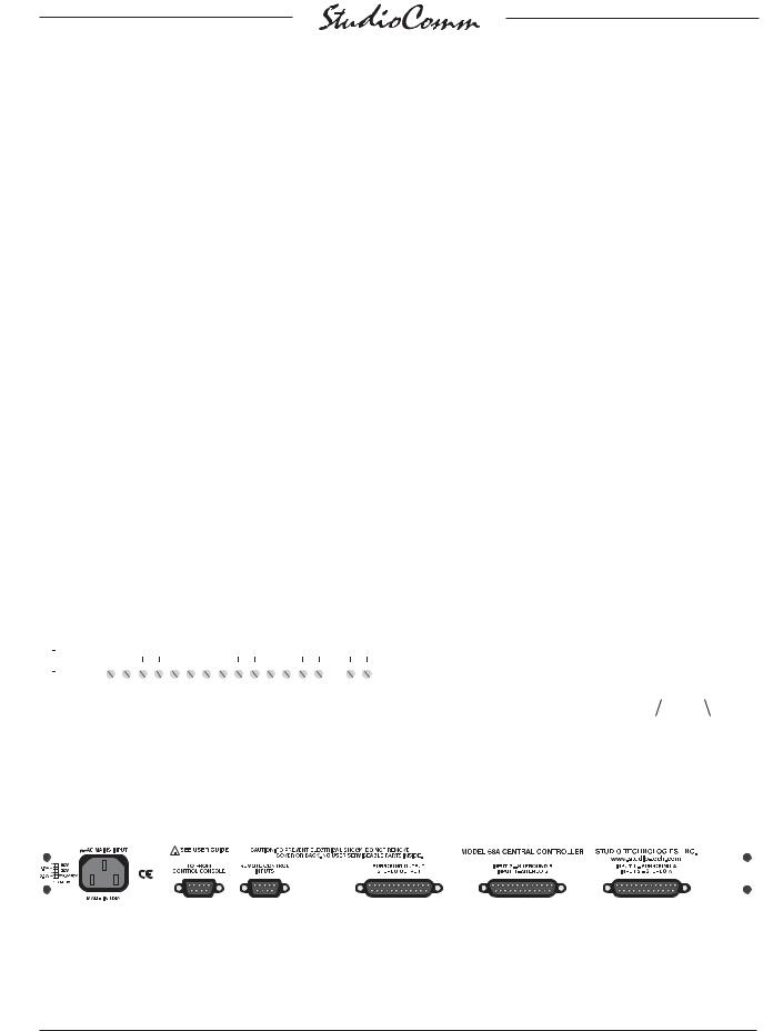
Model 68A Central Controller
The Model 68A Central Controller is a single rack-space unit containing analog audio and digital control circuitry. Audio input and output connections are made using three 25-pin D-subminiature (“D- sub”) connectors. The connectors follow the industry-standard multi-channel wiring scheme. A 9-pin D-sub connector is used to connect the Model 68A to a Model 69A Control Console. A second 9-pin D-sub connector provides access to the remote control inputs.
The Model 68A provides two 6-channel surround and two stereo inputs. Each input circuit uses a 15-turn trim potentiometer
to allow operation with nominal signal levels of –12 dBV to +6 dBu. The 6-chan- nel surround and 2-channel stereo monitor outputs use electronically balanced circuitry. Electromechanical relays provide power-up and power-down loudspeaker protection.
An 8-bit micro-controller provides the logic “horsepower” for the Model 68A. AC mains power is connected directly to the Model 68A, which is factory selected for 100, 120, 220/240 V operation. The internal power supply utilizes a toroidal mains transformer for quiet audio operation.
Model 69A Control Console
The Model 69A Control Console is a compact, self-contained unit designed to be located at the operator’s position. It allows fingertip control of all monitoring parameters. Numerous LEDs provide complete status information.
Model 68A/69A User Guide |
Issue 2, January 2005 |
Studio Technologies, Inc. |
Page 7 |
for Surround
The Model 69A provides four buttons and associated LEDs for selection of the input source to be monitored. While in most cases only one input source will be monitored at a time, multiple inputs can be selected for simultaneous monitoring. This allows two, three, or all four of the inputs to be combined (“summed”). While there is no independent control of the input levels, this feature can be useful for creating rough mixes from the source signals. It is also a fast, effective means of making a “seat-of- the-pants” check on the phase relationship between synchronized signals.
The monitor output level is controlled either through the use of a large, easy- to-use rotary control, or by enabling the preset reference level. For operator convenience, the dim function allows the monitor output level to be reduced by a fixed dB
amount. The mute all function disables all monitor outputs by activating the mute relays on the Model 68A Central Control-
ler. A pushbutton switch allows selection of either the 6-channel surround or the
2-channel stereo monitor output.
Control of the individual monitor output channels is provided by the mute/solo section. One pushbutton switch sets the operating mode for either mute or solo. The flexibility of having both mute and solo available allows an operator to quickly
select the most comfortable and productive operating mode. In the mute mode, individual channels can be muted or unmuted as required. In the solo mode, one channel can be monitored while the others are automatically muted. If desired, multiple channels can be simultaneously selected for “soloing.”
Figure 1. Model 68A Central Controller Front Panel
|
|
|
|
|
|
|
|
|
|
|
|
|
|
|
|
|
|
|
|
|
|
|
|
|
|
|
|
|
|
|
|
|
|
|
|
|
|
|
|
|
|
|
|
|
|
|
|
|
|
|
|
|
|
|
|
|
|
|
|
|
|
|
|
|
|
|
|
|
Input 1 – |
|
Input 2 – |
Input 3 – |
Input 4 – |
Data |
Power |
|||||||||
|
Surround A |
|
Surround B |
Stereo A |
Stereo B |
active LED |
present LED |
|||||||||
|
trim pots |
|
trim pots |
trim pots |
trim pots |
|
|
|||||||||
Figure 2. Model 68A Central Controller Back Panel
|
|
|
|
|
|
|
|
|
|
|
|
|
|
|
|
|
|
|
|
|
|
|
|
|
|
|
|
|
|
|
|
|
|
|
|
|
|
|
|
|
|
|
|
|
|
|
|
|
|
|
|
|
|
|
|
|
|
|
|
|
|
|
|
|
|
|
|
|
|
|
|
|
|
|
|
|
|
|
|
|
|
|
|
|
|
|
|
|
|
|
|
|
|
|
|
|
|
|
|
|
|
|
|
|
|
|
|
|
|
|
|
|
|
|
|
|
|
|
|
|
|
|
|
|
|
|
|
|
|
|
|
|
|
|
|
|
AC mains |
To/from |
Remote control |
Surround and |
Input 2 – Surround B |
Input 1 – Surround A |
||||||||||
|
connection |
Model 69A |
connections |
stereo monitor |
and Input 4 – Stereo B |
and Input 3 – Stereo A |
||||||||||
|
|
|
|
|
Control Console |
|
|
output connections |
connections |
connections |
||||||
Issue 2, January 2005 |
Model 68A/69A User Guide |
Page 8 |
Studio Technologies, Inc. |

for Surround
Monitor output channel mute/solo
Mute/solo mode select
Mono |
|
Downmix |
Surround/stereo |
|
|
|
output select |
Input |
Monitor Output |
Sources |
|
|
• Reference level |
|
• Mute all |
|
• Dim |
|
• Rotary level control |
Figure 3. Model 69A Control Console Front Panel
Two functions allow the format of the monitored signals to be checked for level or phase inconsistencies. The downmix function is used to create a 2-channel stereo signal from a surround source. The mono function allows a stereo signal to be added (summed) and monitored by either the left channel and right channel monitor outputs, or the center channel monitor output. The downmix and mono functions can be enabled at the same time, allowing a surround signal to be checked for mono compatibility.
A bandpass filter can be inserted into the path of the mono signal when it is being routed to the center channel. This allows the simulation of the response of a loudspeaker associated with an inexpensive monaural television or portable radio.
A major strength of the Model 69A is the ability to configure, under software control, many operating parameters. This allows
operation to be tailored to meet the characteristics of an installation. In addition, the specific operating preferences desired by a facility or individual user are selected.
To meet future needs, all configurations can be changed at any time. All configuration parameters are stored in non-volatile memory.
A Model 69A Control Console connects to the Model 68A Central Controller using a standard 9-pin D-sub cable. Power for the Model 69A is provided by the Model
68A. The Model 69A generates MIDI system-exclusive messages to control the Model 68A. Remote control signals, while physically connected to the Model 68A, route to the Model 69A via conductors in the 9-pin D-sub interconnecting cable.
Remote Control Capability
Three remote control functions are available: mute all, dim, and input select.
Remote mute all and remote dim are
Model 68A/69A User Guide |
Issue 2, January 2005 |
Studio Technologies, Inc. |
Page 9 |

for Surround
provided so that communications systems, machine control systems, or communication functions associated with audio consoles can easily be interfaced. Remote input select allows a machine control system or audio storage device to control which input source is selected for monitoring. Audio-post professionals will know this as PEC-Direct switching.
Limitations on Signal Routing
While the StudioComm Model 68A/Model 69A will do many wonderful things, it is not designed to selectively route input signals to the different monitor output channels.
A fixed input-channel-to-output-channel relationship is maintained. A signal on the LFE channel of Surround B will, when selected, output only on the LFE channel of the monitor output. Any rerouting of the input signals must be done prior to connection to the StudioComm system. This
should not be an impairment in most facilities, but it’s important to highlight this fact.
Audio Channel Assignment
The designers of the StudioComm Models 68A and 69A made the decision to assign the audio channels in the order of left, center, right, left surround, right surround, and LFE. It was felt that this was a convenient, rational arrangement, common
to many “5.1” installations and one that would fit the needs of most operators.
However, not all formats follow this convention. Major audio companies such as Dolby Laboratories and DTS may use different channel assignment schemes in their release formats. It is hoped that careful interconnection of audio signals during installation, or incorporating routing flexibility using a patch bay, will mitigate any significant inconveniences.
Installation
In this section you will be installing the Model 68A Central Controller in an equipment rack. Audio input and monitor output connections will be made. A location will be selected for the Model 69A Control Console and it will be connected to the Model 68A. If required, external equipment will be interfaced to the remote control inputs. AC mains power will be connected to the Model 68A.
System Components
The shipping carton contains one each of the following: Model 68A Central Controller, Model 69A Control Console, 20-foot (6.1 m) 9-pin D-sub interconnecting cable, user guide, and warranty card. Units destined for North America also include an AC mains cord. Your dealer or distributor will provide an AC mains cord for non-North American destination.
Mounting the Model 68A
The Model 68A Central Controller requires one space in a standard 19-inch (48.3 cm) equipment rack. Select a location that is convenient to both the analog audio signals and the Model 69A Control Console. A 20-foot (6.1 m) cable is supplied to connect the Model 68A to the Model 69A. You can supply your own interconnecting cable, however 50 feet (15.3 m) is the recommended maximum length. Secure the
Model 68A into the equipment rack using two mounting screws per side.
Audio Connections
Audio signal connections are made by way of three 25-pin D-sub connectors, located on the Model 68A’s back panel. Three cable harnesses, each with a
Issue 2, January 2005 |
Model 68A/69A User Guide |
Page 10 |
Studio Technologies, Inc. |
for Surround
25-pin D-sub plug (male) on one end and the desired connectors on the other end, are necessary. These cable harnesses are not supplied by Studio Technologies. Note that our friends in some locations may
use the term “loom” instead of harness.
The wiring scheme used by the D-subs comply with that made familiar by
TASCAM® with their DA-88® product. Wiring harnesses prepared for connecting to the surround and stereo inputs are identical to DA-88-style input harnesses.
A wiring harness prepared for the monitor outputs is identical to that of a DA-88-style output harness. Please refer to Figures 4,
5, and 6 for the exact connection details. Note that the Model 68A’s D-sub connectors use 4-40 threads.
Unless there’s a special need, it may be cost and time effective for you to purchase commercially made cable harnesses. Let the large market for DA-88-style cabling help you painlessly install your system!
|
Signal |
Signal |
|
Connections |
High (+) |
Low (–) |
Shield |
SURROUND A-L |
24 |
12 |
25 |
SURROUND A-C |
10 |
23 |
11 |
SURROUND A-R |
21 |
9 |
22 |
SURROUND A-LS |
7 |
20 |
8 |
SURROUND A-RS |
18 |
6 |
19 |
SURROUND A-LFE |
4 |
17 |
5 |
STEREO A-L |
15 |
3 |
16 |
STEREO A-R |
1 |
14 |
2 |
Notes: 1) Connector type on Model 68A is 25-pin D-subminiature female. Installer must provide plug (male). Connector uses 4-40 threaded inserts for locking with mating plug.
2) Wiring scheme follows TASCAM DA-88 convention. Standard DA-88-type wiring harnesses are directly compatible, with the exception of 4-40 screw threads being required.
Figure 4. Connections for Inputs Surround A and Stereo A
|
Signal |
Signal |
Connections |
High (+) |
Low (–) Shield |
Surround and Stereo Inputs
The connectors labeled Input 1 – Surround A & Input 3 – Stereo A and Input 2 –
Surround B & Input 4 – Stereo B are used to interface with the input circuits. Please refer to Figures 4 and 5 for details on the exact “pin out” of the D-sub connectors. Each input circuit is electronically balanced, and is intended for connection to balanced or unbalanced sources
with nominal signal levels of –12 dBV to +6 dBu. A 15-turn trim potentiometer is associated with each input, allowing the input sensitivity to be adjusted to match the source’s level. The configuration section of this guide provides details on using the trim pots.
SURROUND B-L |
24 |
12 |
25 |
SURROUND B-C |
10 |
23 |
11 |
SURROUND B-R |
21 |
9 |
22 |
SURROUND B-LS |
7 |
20 |
8 |
SURROUND B-RS |
18 |
6 |
19 |
SURROUND B-LFE |
4 |
17 |
5 |
STEREO B-L |
15 |
3 |
16 |
STEREO B-R |
1 |
14 |
2 |
Notes: 1) Connector type on Model 68A is 25-pin D-subminiature female. Installer must provide plug (male). Connector uses 4-40 threaded inserts for locking with mating plug.
2) Wiring scheme follows TASCAM DA-88 convention.
Standard DA-88-type wiring harnesses are directly compatible, with the exception of 4-40 screw threads being required.
Figure 5. Connections for Inputs Surround B and Stereo B
Model 68A/69A User Guide |
Issue 2, January 2005 |
Studio Technologies, Inc. |
Page 11 |
for Surround
Balanced sources should be wired so that signal high is connected to +, signal low to –, and shield to the shield connection. With an unbalanced source, connect signal high to the + connection, and shield to both the – and the shield connections. If
connecting to an unbalanced source in this manner results in hum or noise, try connecting signal high to +, and shield to –; leave the shield connection unterminated.
It is highly recommended that at least one of the surround inputs be wired by way
of an audio patch bay. This will allow the channels associated with that input source to be easily rerouted. While signals generated within a facility will normally follow a specific format, such as left, center, right, left surround, right surround, LFE, it is possible that media provided by an outside facility will follow a different one.
Monitor Outputs
The connector labeled Surround Output Stereo Output provides access to the 6-channel surround and 2-channel stereo monitor outputs. Please refer to Figure 6 for details on the exact “pin out” of the
D-sub connector.
The monitor output channels are intended for connection to audio amplifiers associated with monitor loudspeakers, or to the inputs of loudspeakers that contain integrated amplifiers. The monitor outputs are electronically balanced and capable of driving balanced or unbalanced loads of 600 ohms or greater. While balanced operation is preferred, unbalanced operation does not pose a problem. To connect to an unbalanced load connect the +
terminal as signal high, and both the – and shield as the signal low/shield. For optimal unbalanced operation, it is important to
|
Signal |
Signal |
|
Connections |
High (+) |
Low (–) |
Shield |
SURROUND OUT-L |
24 |
12 |
25 |
SURROUND OUT-C |
10 |
23 |
11 |
SURROUND OUT-R |
21 |
9 |
22 |
SURROUND OUT-LS |
7 |
20 |
8 |
SURROUND OUT-RS |
18 |
6 |
19 |
SURROUND OUT-LFE |
4 |
17 |
5 |
STEREO OUT-L |
15 |
3 |
16 |
STEREO OUT-R |
1 |
14 |
2 |
Notes: 1) Connector type on Model 68A is 25-pin D-subminiature female. Installer must provide plug (male). Connector uses 4-40 threaded inserts for locking with mating plug.
2) Wiring scheme follows TASCAM DA-88 convention.
Standard DA-88-type wiring harnesses are directly compatible, with the exception of 4-40 screw threads being required.
Figure 6. Connections for Surround and Stereo Monitor Outputs
connect both – and shield together directly on the D-sub plug, not at the other end of the harness.
Note that while the Model 68A’s electronically balanced output circuits are capable of driving loads of 600 ohms or greater, the output level will drop slightly as the load impedance approaches 600 ohms.
A 0.5 dB difference in output level can be expected as the load impedance changes from 10 k ohms to 600 ohms.
Remote Control Inputs
Support is provided for three remote control input functions: mute all, dim, and input select. The inputs use logic gates, “pulled up” to +5 V by way of resistors, which are active when brought to the logic low state. Inputs of this type are commonly referred to as GPI inputs. While the input circuitry is protected from over-current and static
(ESD) discharge, care should be taken to
Issue 2, January 2005 |
Model 68A/69A User Guide |
Page 12 |
Studio Technologies, Inc. |

for Surround
prevent nasty signals from reaching them.
The inputs are active only when held in the low state; they can’t be configured to change state (“latch”) in response to a logic pulse.
The connector labeled Remote Control Inputs on the back panel of the Model
68A is used to interface with the remote control inputs. Refer to Figure 7 for exact connection details. Note that pin 1 (Shield) and pin 9 (Remote Control Common) are electrically identical. In addition to connecting to system common, they connect to the
Model 68A’s chassis and mains earth connection. For convenience, the shield of the interconnecting cable should be connected to pin 1 (Shield), while the return signals of the remote control sources should connect to pin 9 (Remote Control Common).
Note that although the remote control connections are physically made to the
D-sub on the Model 68A’s back panel, the remote control input circuitry is actually located in the Model 69A Control Console.
Conductors in the cable linking the Model 68A to the Model 69A route the remote control signals to the actual input circuitry.
Pin Signal
Connecting the Model 68A to the Model 69A
A cable with 9-pin D-sub plugs (males) on each end is used to interconnect the Model 68A Central Controller with the Model 69A Control Console. A 20-foot (6.1-meter) cable is provided with each system. The connector labeled To/From
Control Console on the back panel of the Model 68A is used to connect to the Model 69A.
Should a cable of different length be required, it should be wired in a one-to-one fashion for all 9 pins. Pin 1 carries signal common, and must be connected at both ends. A shield connection for the cable should be connected to pin 1 on the Model 68A’s end. For best performance the cable generally should not exceed 50 feet (15.3 meter) in length. The reality is that a cable much longer in length should work correctly, as long as an excellent-quality cable is utilized. We define “excellent” as extensive shielding along with very low capacitance. The low cable capacitance is important
as it limits the amount of data-signal waveform distortion. As far as an actual maximum length, just test and see how far away you can go—if it works, it works!
1Shield
5Remote Mute All
6Remote Dim
7Spare Remote Input
8Remote Input Select
9Remote Control Common
Notes: 1) Connector type on Model 68A is 9-pin D-subminiature female. Installer must provide plug (male). Connector uses 4-40 threaded inserts for locking with mating plug.
Figure 7. Connector Pin Out for Remote Control Inputs
AC Mains Power
The Model 68A is internally configured to operate from either nominal 100, 120, or 220/240 V, 50/60 Hz. Units shipped to North America are factory selected for 120 V operation. Units bound for Japan must be selected for 100 V, while our friends “down under” and in Europe receive units set for 220/240 V. Before connecting the Model 68A to AC mains
power, check that it is configured to match the local mains voltage. Look on the back
Model 68A/69A User Guide |
Issue 2, January 2005 |
Studio Technologies, Inc. |
Page 13 |
for Surround
panel (adjacent to the power entry connector) for the factory-configured voltage. Note that an incorrect configuration could prevent operation, or cause damage to the unit. Should it be necessary to change the unit’s operating voltage it must be performed only at the factory or by an authorized service technician.
The Model 68A uses an IEC-standard connector to mate with the AC mains cord. The wire colors in the AC mains cord should conform to the internationally recognized CEE color code and must
be wired accordingly:
Connection |
Wire Color |
Neutral (N) |
Light Blue |
Line (L) |
Brown |
Protective Earth (E) |
Green/Yellow |
Safety Warning: The Model 68A does not contain an AC mains disconnect switch. As such, the AC mains cord plug serves as the disconnection device. Safety considerations require that the plug and associated outlet be easily accessible to allow rapid disconnection of AC mains power should it prove necessary.
As soon as AC mains power is applied, the Model 68A’s power present LED will light. The Model 69A will go through a power-up sequence, lighting each LED in secession. The data active LED on the Model 68A will briefly light upon completion of the Model 69A’s power-up sequence.
Configuration
After the physical installation has been completed, several configuration issues must be addressed. On the Model 68A the surround and stereo inputs must be calibrated using the trim potentiometers. The operating parameters of the system should be set using the Model 69A Control Console’s configuration mode.
Level Calibration
Sixteen 15-turn trim potentiometers are located on the front panel of the Model 68A Central Controller. Taking time to carefully adjust the trim pots will ensure that accurate monitoring can take place. Each trim pot allows input signals with a nominal level of –12 dBV to +6 dBu to be utilized. With care, it’s easy to calibrate the surround and stereo inputs to within onequarter of a dB of the desired value.
The monitor outputs are used as the measuring point when adjusting the trim pots. A laboratory-grade audio level meter, or equivalent, is required for accurate calibration. In addition, the audio sources connected to the inputs must be able to generate continuous audio signals at their nominal operating level.
Procedure
This procedure will calibrate the surround and stereo input channels. The trim pots will be adjusted in groups corresponding to their associated input sources.
1.Begin by turning the audio amplifiers or amplified speakers to their off state. This will protect the loudspeakers
and the operator’s ears from possible damage.
Issue 2, January 2005 |
Model 68A/69A User Guide |
Page 14 |
Studio Technologies, Inc. |

for Surround
2.Rotate the level control on the Model
69A to the fully clockwise (maximum) position.
3.Using the Model 69A Control console, select Surround A as the input source and Surround as the selected monitor output.
4.On the Model 68A, connect the audio level meter to the left channel of the surround monitor output.
5.Confirm that the audio source’s left channel is generating a steady signal at precisely its reference level.
6.Observing the level meter, adjust input 1, trim pot L, to give a precise +4 dBu level at surround monitor output L.
7.Disconnect the level meter from the left channel of the surround monitor output.
8.Repeat steps 4-7 for the center, right, left surround, right surround, and LFE channels of Surround A.
9.Repeat steps 3-8 for Surround B, Stereo A, and Stereo B. Obviously, the stereo inputs have only left and right inputs, requiring only that two trim pots be adjusted for each.
10.Rotate the level control on the Model 69A to the fully counterclockwise (minimum) position.
11.After ensuring that the Model 69A’s level control is set to minimum, return
AC mains power to the power amps or amplified speakers.
Model 69A Operating
Parameters
Many StudioComm functions can be con-
figured to meet the exact needs of your installation. Here’s an overview of what you can configure:
•Input channels active
•Stereo output
•Solo mode
•Power-up mute all
•Level control response
•Level control auto mute all
•Reference level
•Remote control inputs
•Dim level
•Auto dim off
•Mono
The Model 69A configuration diagrams, located at the end of this section, give details on how each parameter is set. An overview of each configurable parameter is provided in the following paragraphs.
Entering and Exiting the Configuration
Mode
A small button is located on the back of the Model 69A Control Console, adjacent to the 9-pin D-sub connector. Pressing and holding this button for two seconds places the Model 69A into the configuration mode. In the configuration mode the Model 69A’s array of buttons and LEDs no longer perform their normal functions, but instead allow you to observe and change many of the operating parameters. The mute/solo mode LEDs light alternately to indicate that the configuration mode is active.
Model 68A/69A User Guide |
Issue 2, January 2005 |
Studio Technologies, Inc. |
Page 15 |
Loading...