


for Surround
Model 68 Central Controller and
Model 69 Control Console
User Guide
Issue 2, June 1999
This User Guide is applicable for systems consisting of:
Model 68: serial number M68-00261 and later;
Model 69: M69-00151 and later, with software version 1.04 and higher
© 1999 by Studio Technologies, Inc., all rights reserved
5520 West Touhy Avenue Skokie, Illinois 60077 U.S.A. Telephone (847) 676-9177 Fax (847) 982-0747 www.studio-tech.com
50082-699, Issue 2

for Surround |
|
Table of Contents |
|
Foreword ..................................................................... |
5 |
Introduction ................................................................. |
7 |
Applications ................................................................. |
10 |
Installation ................................................................... |
11 |
Configuration ............................................................... |
15 |
Operation .................................................................... |
29 |
Technical Notes .......................................................... |
32 |
Specifications .............................................................. |
34 |
Appendix A .................................................................. |
35 |
MIDI Messages ....................................................... |
36 |
Block Diagrams |
|
Model 68 Central Controller |
|
Model 69 Control Console |
|
Model 68/69 User Guide |
Issue 2, June 1999 |
Studio Technologies, Inc. |
Page 3 |

for Surround
This page intentionally left blank.
Issue 2, June 1999 |
Model 68/69 User Guide |
Page 4 |
Studio Technologies, Inc. |

for Surround
Foreword
Simply stated: I had a blast working on the StudioComm for Surround components! It was very rewarding to develop a set of products for a market that’s actually receptive to new ideas and supportive of innovation.
A big thanks to Jeff Levison, formerly of Warner Hollywood Studios. He patiently answered my questions over a period of many months, helping to guide me in the right direction. I recently read an interesting book on the history of the Warner Brothers and their movie empire. One of the things that stood out was their long-term commitment to audio. From the Jazz Singer to the current DVD releases, they haven’t been afraid of staying on the forefront of sound for picture. Good going guys!
Additional thanks to a couple of smart audio dudes. Thierry Jeandroz of LTRT in Paris encouraged me to add several features to improve our audio-post support. Rob James, formerly of the BBC and now a consultant and writer, suggested how the operator interface could be improved. The software now reflects the sage advice of these gentlemen.
Mitch Budniak designed much of the hardware and kept us out of “digital trouble.” Carrie
Loving provided engineering support and designed the product graphics. Larry Leviton wrote the software that makes the hardware “come to life.” Fred Roeck performed the mechanical design. Al “PCB PRO” Lux designed the...you guessed it! Joe Urbanczyk coordinated the safety testing and created the automated test routes for our Audio Precision System Ones.
Our plans are to continue with other StudioComm for Surround components. To help keep us going in the right direction, your praise, comments, or complaints are encouraged. Please contact me via E-mail at gkapes@studio-tech.com.
Sincerely,
Gordon K. Kapes
President
Model 68/69 User Guide |
Issue 2, June 1999 |
Studio Technologies, Inc. |
Page 5 |

for Surround
This page intentionally left blank.
Issue 2, June 1999 |
Model 68/69 User Guide |
Page 6 |
Studio Technologies, Inc. |

for Surround
Introduction
What This User Guide Covers
This User Guide is designed to assist you when installing and using the Model 68
Central Controller and the Model 69 Control Console.
StudioComm for Surround
As the production of multi-channel “surround sound” audio material becomes more prevalent, the need to monitor these sources becomes imperative for more and more facilities. Studio Technologies has addressed the needs of smaller facilities with the StudioComm Model 68 Central
Controller and Model 69 Control Console.
Together they provide the means to select input sources, control the level of monitor loudspeakers, and provide mute and solo functions, along with many other features.
A StudioComm for Surround system starts with a Model 69 Control Console, a compact but comfortable “command center” that is designed to reside at the operator’s location. Using a single 9-conductor cable, it connects to a Model 68 Central Controller. The Model 68 supports two 6-channel inputs, two stereo inputs, and six monitor output channels in a single rack space. Special features are also supported, including interfacing with remote control signals and “tight” integration with stereo mix consoles.
The Models 68 and 69 were developed in conjunction with experts in the postproduction and music-only audio fields. The overall goal turned out to be very straightforward: Provide the necessary technical performance and features, while keeping it simple to operate! Be certain
that operators won’t have to go through a long “learning curve” before they become efficient. The end result achieves these goals, providing the required resources in a simple-to-operate format.
Model 68 Central Controller
The Model 68 Central Controller is a single rack-space unit containing analog audio and digital control circuitry. Audio input and output connections are made using three 25-pin D-subminiature (“D-sub”) connectors. The connectors follow an industry-standard multi-channel wiring scheme. A 9-pin D-sub connector is used to connect the Model 68 to a Model 69 Control Console. A second 9-pin D-sub connector provides access to the remote control inputs.
The surround and stereo inputs, as well as the monitor outputs, are electronically balanced. Fifteen-turn trim potentiometers are used to precisely calibrate the input and monitor output signals. Using electromechanical relays, the 6-channel monitor output provides power-up and power-down protection for the loudspeakers.
The L/R Bypass function allows a stereo line-level audio source to be passively routed to the Model 68’s left and right monitor output channels, while muting the center, left surround, right surround, and subwoofer monitor outputs. The L/R Bypass audio source is normally the monitor output of a stereo audio console. The L/R Bypass function, along with associated remote control functions, make it simple for an existing facility to add surround monitoring capability.
An 8-bit micro-controller provides the logic
“horsepower” for the Model 68. AC mains power is connected directly to the Model
Model 68/69 User Guide |
Issue 2, June 1999 |
Studio Technologies, Inc. |
Page 7 |
for Surround
68, which is factory selected for 100, 120, 220/240V operation. The internal power supply utilizes a toroidal mains transformer for quiet audio operation.
Model 69 Control Console
The Model 69 Control Console is a compact, self-contained unit designed to be located at the operator’s position. It allows fingertip control of all monitoring parameters. Numerous LEDs provide complete status information. The Model 69 supports two 6-channel (surround) and two
2-channel (stereo) input sources, along with one 6-channel monitor output.
The Model 69 provides four buttons and associated LEDs for selection of the input source to be monitored. While in most cases only one input source will be monitored at a time, multiple inputs can be selected for simultaneous monitoring.
This allows two, three, or all four of the inputs to be combined (“summed”). While there is no independent control of the input levels, this feature can be useful
for creating rough mixes from the source signals. It is also a fast, effective means of making a “seat-of-the-pants” check on the phase relationship between synchronized signals.
The monitor output level is controlled either through the use of a large, easy- to-use rotary control, or by enabling the preset reference level. For operator convenience, the dim function allows the monitor output level to be reduced by a fixed dB amount. The mute all function disables all monitor outputs by activating the mute relays on the Model 68 Central Controller.
Figure 1. Model 68 Central Controller Front Panel
|
|
|
|
|
|
|
|
|
|
|
|
|
|
|
|
|
|
|
|
|
|
|
|
|
|
|
|
|
|
|
|
|
|
|
|
|
|
|
|
|
|
|
|
|
|
|
|
|
|
|
|
|
|
|
|
|
|
|
|
|
|
|
|
|
|
|
|
|
Input 1 |
|
Input 2 |
Input 3 |
|
Input 4 |
Data |
Power |
||||||||
|
trim pots |
|
trim pots |
trim pots |
trim pots |
active LED |
present LED |
|||||||||
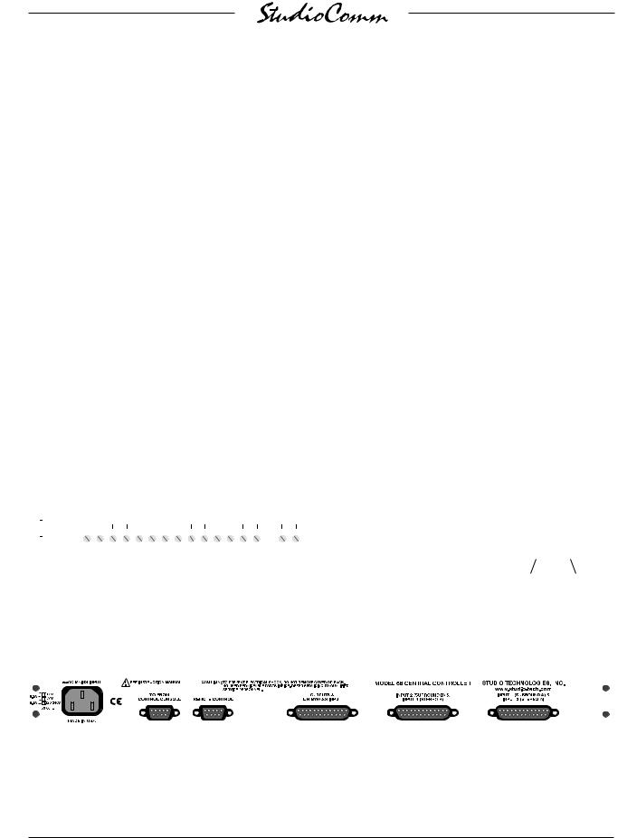
Figure 2. Model 68 Central Controller Back Panel
|
|
|
|
|
|
|
|
|
|
|
|
|
|
|
|
|
|
|
|
|
|
|
|
|
|
|
|
|
|
|
|
|
|
|
|
|
|
|
|
|
|
|
|
|
|
|
|
|
|
|
|
|
|
|
|
|
|
|
|
|
|
|
|
|
|
|
|
|
|
|
|
|
|
|
|
|
|
|
|
|
|
|
|
|
|
|
|
|
|
|
|
|
|
|
|
|
|
|
|
|
|
|
|
|
|
|
|
|
|
|
|
|
|
|
|
|
|
|
|
|
|
|
|
|
|
|
|
|
|
|
|
|
|
|
|
|
AC mains |
To/from |
Remote control |
Monitor outputs |
Input 2 |
Input 1 |
||||||||||
|
connection |
Model 69 |
connections |
and |
(surround B) |
(surround A) |
||||||||||
|
|
|
|
|
Control Console |
|
|
L/R Bypass input |
and input 4 |
and input 3 |
||||||
|
|
|
|
|
|
|
|
|
connections |
(stereo B) |
(stereo A) |
|||||
|
|
|
|
|
|
|
|
|
|
|
connections |
connections |
||||
Issue 2, June 1999 |
Model 68/69 User Guide |
Page 8 |
Studio Technologies, Inc. |

for Surround
Monitor output channel mute/solo
Mute/solo mode select
|
Surround L/R |
|
|
Bypass select |
|
Input |
|
|
Sources |
Monitor Output |
|
1-4 |
||
• Reference level |
||
|
||
|
• Mute all |
|
|
• Dim |
|
|
• Rotary level control |
Figure 3. Model 69 Control Console Front Panel
Control of the individual monitor output channels is provided by the mute/solo section. One push-button switch sets the operating mode for either mute or solo. The flexibility of having both mute and solo available allows an operator to quickly select the most comfortable and productive operating mode. In the mute mode, individual channels can be muted or unmuted as required. In the solo mode, one channel can be monitored while the others are automatically muted. Of course, multiple channels can be simultaneously selected for “soloing.”
A major strength of the Model 69 is the ability to configure, under software control, many operating parameters. During initial installation the Model 69 is “taught” the number of monitor output channels to be controlled, as well as the number of channels associated with the two surround and two stereo inputs. The monitor output reference level is set by taking an elec-
tronic “snapshot” of the position of the rotary level control. The dim level is selected from among four choices. A number of other operating parameters can also be configured, including how the four remote control inputs will function. All configuration parameters are stored in non-volatile memory.
A Model 69 Control Console connects to the Model 68 Central Controller using a standard 9-pin D-sub cable. Power for
the Model 69 is provided by the Model 68.
The Model 69 generates MIDI systemexclusive messages to control the Model 68. Remote control signals, while physically connected to the Model 68, route to the Model 69 via conductors in the 9-pin
D-sub interconnecting cable.
Limitations on Signal Routing
While a StudioComm system for multichannel monitoring will do many wonderful things, it is not designed to selectively
Model 68/69 User Guide |
Issue 2, June 1999 |
Studio Technologies, Inc. |
Page 9 |

for Surround
route input signals to the different monitor output channels. An input-channel-to- output-channel relationship is maintained. A signal on the subwoofer channel of input 2 will, when selected, output only on the subwoofer channel of the monitor output. Any rerouting of the input signals must be done prior to connection to the Studio-
Comm system. This should not be an impairment in most facilities, but it’s important to highlight this fact.
Audio Channel Assignment
The designers of the StudioComm Models 68 and 69 made the decision to assign the audio channels in the order of left, center, right, left surround, right surround, and subwoofer. It was felt that this was a nice, rational arrangement, common to many “5.1” installations, that would fit the needs of most operators. However, not all formats follow this convention, or even use the same nomenclature. Major audio companies such as Dolby Laboratories and DTS may use different channel assignment schemes in their release formats. It is hoped that careful interconnection of audio signals during installation, or incorporating routing flexibility using
a patch bay, will mitigate any big inconveniences.
SUB Versus LFE
The term SUB was selected because of its general popularity, but we understand that some people prefer the term LFE (low-frequency-enhancement). If you’re someone who can’t live with our choice, please feel free to relabel your Studio-
Comm system. Our feelings won’t be hurt—at least not much!
Applications
Remote Control Capability
Four remote control functions are available: Mute all, dim, L/R Bypass, and input select. Remote mute all and remote dim are provided so that communications systems, machine control systems, or communication functions associated with audio consoles can easily be interfaced. Remote L/R Bypass allows an audio console’s solo or PFL functions to remain viable while mixing in surround. Remote input select allows a machine control system, or audio storage device, to control which input source is selected for monitoring. Audio-post professionals will know this as PEC-Direct switching, which can be easily implemented.
L/R Bypass
The L/R Bypass function was expressly provided so that surround monitoring capability could be added to a facility while maintaining compatibility with existing stereo monitoring systems. The L/R
Bypass signal source would normally be the stereo monitor output of an audio console. During normal surround mode operation of the Model 68 and Model 69, the left and right monitor outputs are connected, via electromechanical relays, to the Model 68’s output circuitry. When the L/R Bypass function is enabled, the left and right monitor outputs disconnect from the Model 68’s output circuits, and connect to the L/R Bypass Inputs; the other four monitor output channels mute. Activation of the L/R Bypass function can be by means of a button on the Model 69 Control
Console, or via a signal connected to the
L/R Bypass remote input.
Issue 2, June 1999 |
Model 68/69 User Guide |
Page 10 |
Studio Technologies, Inc. |
for Surround
Installation
In this section you will be installing the Model 68 Central Controller in an equipment rack. Audio input and monitor output connections will be made. A location will be selected for the Model 69 Control Console and it will be connected to the Model 68. If required, external equipment will be interfaced to the remote control inputs. AC mains power will be connected to the Model 68.
System Components
The shipping carton contains one each of the following: Model 68 Central Controller, Model 69 Control Console, 20-foot (6.1m) 9-pin D-sub interconnecting cable, user guide, and warranty card. Units destined for North America also include an AC mains cord. Your dealer or distributor will provide an AC mains cord for non-North
American destination.
Mounting the Model 68
The Model 68 Central Controller requires one space in a standard 19-inch (48.3cm) equipment rack. Select a location that is convenient to both the analog audio signals and the Model 69 Control Console.
A 20-foot (6.1m) cable is supplied to connect the Model 68 to the Model 69. You can supply your own interconnecting cable, however 50 feet (15.3m) is the recommended maximum length. Secure the Model 68 into the equipment rack using two mounting screws per side.
Cable Harnesses
Three 25-pin D-sub connectors are utilized for audio input and output interconnections. The 16 line-input channels, desig-
nated input 1 (Surround A), input 2 (Surround B), input 3 (Stereo A), and input 4 (Stereo B), can interface using
two standard DA-88-style input cable harnesses. The 25-pin D-sub harness used for the six monitor output channels and the L/R Bypass input uses a wiring scheme slightly different from the “DA-88 standard;” the L/R Bypass input connections make it different. In a standard DA-
88 output cable harness, all eight channels would use, for example, XLR-type plugs (males). A harness for the Model 68 would have the first six channels using XLR-type plugs (males) and the last two channels XLR-type connectors (females).
Audio Connections
Audio signal connections are made by way of three 25-pin D-sub connectors, located on the Model 68’s back panel. Three cable harnesses, each with a 25-pin D-sub plug (male) on one end and the desired connectors on the other end, are necessary. These cable harnesses are not supplied by Studio Technologies. (Note that our friends in some locations may use the term “loom” instead of harness.)
The wiring scheme used by the D-subs comply with that made familiar by
TASCAM with their DA-88 product. Wiring harnesses prepared for connecting to the surround and stereo input channels are identical to that of a DA-88 input harness. A wiring harness prepared for the monitor output channels and L/R Bypass input are wired in a slightly different fashion. Please refer to Figures 4 and 5 for the exact connection details. Note that the Model 68’s D-sub connectors use 4-40 threads.
Unless there’s a special need, it may be cost and time effective for you to purchase
Model 68/69 User Guide |
Issue 2, June 1999 |
Studio Technologies, Inc. |
Page 11 |
for Surround
commercially made cable assemblies. Let the large market for DA-88-style cabling help you painlessly install your system! When it came time for Studio Technologies to test the first Model 68 Central Controller, standard DA-88 harnesses were purchased. They turned out to be
of very good quality, and the cost was very reasonable. Needing to change the sex of the last two connectors on the output harness (to support the L/R Bypass input) was a trivial matter.
Surround and Stereo Audio Inputs
The connectors labeled INPUT 1 (SURROUND A) & INPUT 3 (STEREO A) and INPUT 2 (SURROUND B) & INPUT 4
(STEREO B) are used to interface with the 16 line input circuits. Each input circuit is electronically balanced, and is intended for connection to balanced or unbalanced sources with a nominal signal level of
|
Signal |
Signal |
|
Connections |
High (+) |
Low (–) |
Shield |
SURROUND A-L |
24 |
12 |
25 |
SURROUND A-C |
10 |
23 |
11 |
SURROUND A-R |
21 |
9 |
22 |
SURROUND A-LS |
7 |
20 |
8 |
SURROUND A-RS |
18 |
6 |
19 |
SURROUND A-SUB |
4 |
17 |
5 |
STEREO A-L |
15 |
3 |
16 |
STEREO A-R |
1 |
14 |
2 |
Notes: 1) Connector type on Model 68 is 25-pin D-subminiature female. Installer must provide plug (male). Connector uses 4-40 threaded inserts for locking with mating plug.
2) Wiring scheme follows Tascam DA-88 convention. Standard DA-88-type wiring harnesses are directly compatible, with the exception of 4-40 screw threads being required.
+4dBu. A trim potentiometer is associated with each input, allowing the input sensitivity to be adjusted over a ±2dB range. The configuration section of this guide provides details on using the trim pots.
Balanced sources should be wired so that signal high is connected to + on the D-sub, signal low to – on the D-sub, and shield to the D-sub’s shield connection. With an unbalanced source, connect signal high to the + connection on the D-sub, and shield to both the – and the shield connection on the D-sub. If connecting to an unbalanced source in this manner results in hum or noise, try connecting signal high to + on the D-sub, and shield to – on the D-sub; leave the shield connection on the D-sub unterminated.
It is highly recommended that at least one of the surround inputs be wired by way of an audio patch bay. This will allow the
|
Signal |
Signal |
|
Connections |
High (+) |
Low (–) |
Shield |
SURROUND B-L |
24 |
12 |
25 |
SURROUND B-C |
10 |
23 |
11 |
SURROUND B-R |
21 |
9 |
22 |
SURROUND B-LS |
7 |
20 |
8 |
SURROUND B-RS |
18 |
6 |
19 |
SURROUND B-SUB |
4 |
17 |
5 |
STEREO B-L |
15 |
3 |
16 |
STEREO B-R |
1 |
14 |
2 |
Notes: 1) Connector type on Model 68 is 25-pin D-subminiature female. Installer must provide plug (male). Connector uses 4-40 threaded inserts for locking with mating plug.
2) Wiring scheme follows Tascam DA-88 convention. Standard DA-88-type wiring harnesses are directly compatible, with the exception of 4-40 screw threads being required.
Figure 4. Connections for Inputs Surround A and Stereo A
Figure 5. Connections for Inputs Surround B and Stereo B
Issue 2, June 1999 |
Model 68/69 User Guide |
Page 12 |
Studio Technologies, Inc. |
for Surround
channels associated with that input source to be easily rerouted. While signals generated within a facility will normally follow a specific format, such as left, center, right, left surround, right surround, subwoofer,
it is possible that media provided by an outside facility will follow a different one.
L/R Bypass Input
The connector labeled OUTPUTS & L/R
BYPASS INPUT provides access to the
L/R Bypass input. Please refer to Figure
6 for details on the exact “pin out” of the
D-sub connector. It is usual for the source connected to the L/R Bypass Input to be from the stereo monitor output of an audio console, or other monitoring system.
Warning: It is very important that signals connected to the L/R Bypass input be “post” a level control, i.e., attenuated from line level. Connecting a standard line level audio signal can result in damage to monitor loudspeaker systems and, more importantly, to the ears of listeners.
Balanced sources should be wired so that signal high is connected to + on the D-sub, signal low to – on the D-sub, and shield to the D-sub’s shield connection. With an unbalanced source the connection method depends on the requirements of the monitor speaker system’s input. This is because routing of the L/R Bypass input to the left and right monitor outputs does not involve any active circuitry. Whenever the
L/R Bypass feature is active, the signal connected to the L/R Bypass input is simply passed through to the left and right monitor output channels by means of electromechanical relay contacts.
Monitor Outputs
The connector labeled OUTPUTS & L/R BYPASS INPUT provides access to
the six monitor output channels. Please refer to Figure 6 for details on the exact “pin out” of the D-sub connector.
The monitor output channels are intended for connection to audio amplifiers associated with monitor loudspeakers, or to the inputs of loudspeakers with integrated amplifiers. The monitor outputs are electronically balanced and capable of driving balanced or unbalanced loads of 600 ohms or greater. While balanced operation is preferred, unbalanced operation does not pose a problem. To connect to an unbalanced load connect the + terminal
of the D-sub as signal high, and both the
– and shield as the signal low/shield. For
|
Signal |
Signal |
|
Connections |
High (+) |
Low (–) |
Shield |
OUTPUT-L |
24 |
12 |
25 |
OUTPUT-C |
10 |
23 |
11 |
OUTPUT-R |
21 |
9 |
22 |
OUTPUT-LS |
7 |
20 |
8 |
OUTPUT-RS |
18 |
6 |
19 |
OUTPUT-SUB |
4 |
17 |
5 |
L/R BYPASS INPUT-L |
15 |
3 |
16 |
L/R BYPASS INPUT-R |
1 |
14 |
2 |
Notes: 1) Connector type on Model 68 is 25-pin D-subminiature female. Installer must provide plug (male). Connector uses 4-40 threaded inserts for locking with mating plug.
2) Wiring scheme loosely follows Tascam DA-88 convention. Modified DA-88-type wiring harnesses are required, along with 4-40 screw threads.
Figure 6. Connections for Monitor Outputs and L/R Bypass Input
Model 68/69 User Guide |
Issue 2, June 1999 |
Studio Technologies, Inc. |
Page 13 |

for Surround
optimal unbalanced operation, it is important to connect both – and shield together directly on the D-sub, and not at the other end of the harness.
Note that while the Model 68’s electronically balanced output circuits are capable of driving loads of 600 ohms or greater, the output level will drop slightly as the load impedance approaches 600 ohms. A 0.5dB difference in output level can be expected as the load impedance changes from 10k ohms to 600 ohms.
Be aware that whenever the L/R Bypass function is enabled, the Model 68’s left and right output circuitry is disabled, and the L/R Bypass inputs are routed directly to the left and right monitor output connections. Ensure that the source of the L/R Bypass signal is capable of correct operation with the wiring scheme selected.
Remote Control Inputs
Support is provided for four remote control functions: Remote Mute All, Remote Dim, Remote L/R Bypass, and Remote Input Select. The four inputs use logic gates, “pulled up” to +5V by way of resistors, which are active when brought to the logic low state. (Inputs of this type are commonly referred to as GPI inputs.) While the input circuitry is protected from overcurrent and static (ESD) discharge, care should be taken to prevent nasty signals from reaching them. The inputs are active only when held in the low state; they can’t be configured to change state (“latch”) in response to a logic pulse.
The connector labeled REMOTE CONTROL on the back panel of the Model 68 is used to interface the four remote control inputs. Refer to Figure 7 for exact connection details. Note that pin 1 (shield) and pin
9 (remote control common) are electrically identical. In addition to connecting to system common, they connect to the
Model 68’s chassis and mains earth connections. For convenience, the shield of the interconnecting cable should be connected to pin 1 (shield), while the return signals of the remote control sources should connect to pin 9 (remote control common).
Note that although the remote control connections are physically made to the
D-sub on the Model 68’s back panel, the remote control input circuitry is actually located in the Model 69 Control Console. Four conductors in the cable linking the Model 68 to the Model 69 route the remote control signals to the actual input circuitry.
Connecting the Model 69 to a Model 68
A cable with 9-pin D-sub plugs (males) on each end is used to interconnect the Model 69 Control Console with the
Model 68 Central Controller. A 20-foot (6.1-meter) cable is provided with each system. The connector labeled TO/FROM
Pin Signal
1 Shield
5Remote Mute All
6Remote Dim
7Remote L/R Bypass
8Remote Input Select
9Remote Control Common
Notes: 1) Connector type on Model 68 is 9-pin D-subminiature female. Connector uses 4-40 threaded inserts for locking with mating plug.
Figure 7. Connector Pin Out for Remote Control Inputs
Issue 2, June 1999 |
Model 68/69 User Guide |
Page 14 |
Studio Technologies, Inc. |
 Loading...