

Page 1

Model 2 Central Controller
and Related Components
User Guide
This User Guide is applicable for Model 2 serial numbers:
M2-00151 and later
Issue 7, November 2001
© 2001 by Studio Technologies, Inc., all rights reserved
5520 West Touhy Avenue
Skokie, Illinois 60077 U.S.A.
Telephone (847) 676-9177
Fax (847) 982-0747
www.studio-tech.com
support@studio-tech.com
50131-1101, Issue 7
Page 2

This page intentionally left blank.
Page 3

Table of Contents
Foreword .............................................................................................. 5
Introduction ....................................................................................... 7
What This User Guide Covers...................................................... 7
Model 2 Central Controller ........................................................... 8
Model 22 Access Station ............................................................. 11
Model 32 & Model 33 Talent Amplifiers ....................................... 11
Installation ......................................................................................... 12
Locating the Unit .......................................................................... 12
Mounting ....................................................................................... 13
Program Inputs............................................................................. 13
Auxiliary Audio Input .................................................................... 13
Talent Amplifier Output ................................................................ 14
Line Outputs ................................................................................. 14
Connecting Telephone Lines ....................................................... 15
Access Stations .......................................................................... 16
Monitor Output ........................................................................... 18
Connecting AC Mains Power ..................................................... 18
Operation .......................................................................................... 19
The Model 2’s Front-Panel Controls and Indicators ................. 19
It’s Time to Use the System! ...................................................... 22
Technical Notes ................................................................................ 23
Circuit Descriptions .......................................................................... 29
Model 2 Central Controller ......................................................... 29
Model 22 Access Station ........................................................... 38
Model 32 Talent Amplifier .......................................................... 40
Model 33 Talent Amplifier .......................................................... 41
Troubleshooting ............................................................................... 42
Model 2 Central Controller ......................................................... 42
Model 22, Model 32, & Model 33 ............................................... 43
Specifications ................................................................................... 45
Figure 1 — Model 2 Rear Bracket Mounting Hole Location Diagram
Figure 2 — Model 25A 19-Inch Rack Adapter Diagram
Figure 3 — Model 28A Panel Adapter Diagram
Figure 4 — Model 22 Access Station Diagram
Block Diagrams
Model 2 Central Controller
Model 22 Access Station
Model 32 Talent Amplifier
Model 33 Talent Amplifier
Model 2 User Guide Issue 7, November 2001
Studio Technologies, Inc. Page 3
Page 4

This page intentionally left blank.
Issue 7, November 2001 Model 2 User Guide
Page 4 Studio Technologies, Inc.
Page 5

Foreword
Many people contributed to the creation of the Model 2 and related items. In general, a
good time was had by all—with lots of takeout Chinese food eaten in the process! Jim
Cunningham designed most of the analog circuitry. Mitch Budniak did the logic and
power supply work. Al Lux designed the printed circuit boards. Carrie Loving provided
engineering support and kept track of numerous design changes. Fred Roeck designed
the mechanicals and lobbied hard for the color green on the front panel. Joe Urbanczyk
implemented the computerized testing procedures on our Audio Precision System One.
Studio Technologies is receptive to your comments and questions. Please contact me with
your questions, comments, and suggestions. I can be reached by voice at (847) 676-9177,
fax at (847) 982-0747, or via the Internet @ www.studio-tech.com.
Sincerely,
Gordon K. Kapes
President
Model 2 User Guide Issue 7, November 2001
Studio Technologies, Inc. Page 5
Page 6

This page intentionally left blank.
Issue 7, November 2001 Model 2 User Guide
Page 6 Studio Technologies, Inc.
Page 7

Introduction
The IFB Plus Series Model 2 Central
Controller from Studio Technologies is a
highly integrated, two-channel IFB (interrupted foldback or interrupted feedback)
system contained in a single rack space
unit. It is expressly designed to provide
talent cueing for ENG, SNG, and mobile
production facilities. The performance
and features of the Model 2 reflect the
needs of contemporary applications. Only
after extensive polling of field production
and engineering personnel was the Model
2’s feature group established. We think
you’ll find the Model 2 a great addition
to your facility.
What This User Guide Covers
This User Guide applies to Studio Technologies, Inc. IFB Plus Series Model 2
Central Controllers with a serial number
of M2-00151 and later. If you are installing a Model 2 with a serial number of
M2-00122 or earlier, please contact Studio
Technologies to obtain the appropriate
documentation.
This guide is designed to assist you
when installing, configuring, and using
the Model 2 Central Controller. It also
contains detailed service information
and block diagrams. A separate packet,
provided with the User Guide, contains
the schematic diagrams.
The following items will be covered in this
User Guide:
Model 2 Central Controller
An integrated two-channel IFB unit intended for applications where space is at
a premium, yet high performance is still
required. The unit contains everything
required to implement a full-featured
system in a single rack space. Includes
multiple program inputs, integral telephone interfaces, monitor amplifier, internal interrupt microphone, among many
other features. The unit is powered by
120 or 220/240V, 50/60Hz.
Model 22 Access Station
Used by a producer or director to access
the Model 2’s IFB channels. Allows connection of a Studio Technologies Model
11A gooseneck microphone or a line-level
audio source. Contains two lighted push
button switches which display IFB interrupt status. Up to four Model 22s can be
connected to and powered by a Model 2
Central Controller. The Model 25A 19-inch
Rack Adapter allows a Model 22 Access
Station and Model 11A gooseneck microphone to be mounted in a single 19-inch
rack space. The Model 28A Panel Adapter
allows a Model 22 and Model 11A gooseneck microphone to be installed in an
opening made in a table, equipment
console, etc.
Model 32 & Model 33 Talent Amplifiers
The Model 32 and Model 33 Talent
Amplifiers are self-contained “belt pack”
units that drive talent ear pieces or headsets. Up to four Model 32 and/or Model 33
Talent Amplifiers can be connected
to, and powered by, a single Model 2
Central Controller.
The Model 32 is intended for use by on-air
personnel, and contains a source switch,
along with an output level control. Either
IFB channel 1 or IFB channel 2 can be
sent to the talent, along with the desired
audio “volume.”
The Model 33 is unique in that a “mix” of
IFB channels 1 and 2 can be created. Two
Model 2 User Guide Issue 7, November 2001
Studio Technologies, Inc. Page 7
Page 8

level controls, along with a source select
switch, allows camera and production
personnel to hear IFB cues from either
or both channels. This allows IFB signals
intended for both technician and talent
to be simultaneously monitored.
Model 2 Central Controller
Contained in a single rack space unit is
everything required to implement a twochannel IFB system. Features include
multiple program inputs, telephone interfaces, voice-operated (VOX) interrupt,
level meters, monitor amplifier, and internal interrupt microphone. Up to four
Model 22 Access Stations can be connected to the Model 2, allowing producer
or director positions to access the IFB
channels. In addition, up to four Model 32
or Model 33 Talent Amplifiers can be
connected to a Model 2. The Model 32
and 33 allow personnel access to the IFB
channels using a single standard microphone cable.
The Model 2 packs numerous features
into a single, 19-inch rack space.
Standard connectors are used throughout, including 3-pin XLR-type, ¼-inch
2-conductor, 9-position D-subminiature,
and modular telephone (RJ11-type)
jacks. Power is supplied by standard
120 or 220/240V (factory configured),
50/60Hz via a detachable cord.
IFB Channels
The Model 2 contains two independent
IFB channels. Each channel has individual
controls and indicators, including program
source select switches, program level
control, 5-segment LED level meter, and
LED status indicators. We’ll describe one
channel in this paragraph. Six switches
allow the four program inputs and incom-
ing audio from the two telephone interfaces to be selected as program audio.
A level control allows adjustment of the
program audio level relative to the fixed
interrupt audio level. A 5-segment LED
level meter displays the composite IFB
channel audio level, i.e., program and
interrupt audio level. The meter facilitates
the rapid setting of the program level
control, as well as providing a general
indication of the channel’s signal level.
Each channel’s composite IFB audio
signal (program and interrupt audio) is
sent to four places: line output, talent
amplifier output, telephone interface 2,
and monitor amplifier. The line outputs
provide electronically balanced, line-level
signals that interface with external equipment via two XLR-type connectors. The
talent amplifier output provides channel 1
and 2 audio, along with +18Vdc power
on one 3-pin XLR-type connector. Any
combination of up to four Model 32 or 33s
can be connected to the talent amplifier
output.
Program Inputs
The Model 2 contains four program inputs.
Each can be individually assigned to the
two IFB channels, with the ability to assign
multiple program inputs to an IFB channel.
Program signals enter the unit via four
XLR-type connectors on the back panel.
The program inputs are electronically
balanced with a nominal input impedance
of 24k ohms. They feature low noise, low
distortion, and high common mode signal
rejection. Each program input has a trim
potentiometer associated with it. The trim
pots, accessible from the back panel,
allow the nominal +4dBu input level to
be adjusted over a ±8dB range.
Issue 7, November 2001 Model 2 User Guide
Page 8 Studio Technologies, Inc.
Page 9

Program audio is muted whenever an
interrupt takes place. A sophisticated
analog switch is used to give a noise-free
mute with absolutely no clicks or pops! If
desired, a program “dim,” rather than a full
mute can be implemented by adding two
resistors to the Model 2’s circuit board.
Compressor/Limiters
Each IFB channel contains a studio-quality
compressor/limiter. The compressing
function evens out variations in the interrupt audio signals. The limiting function
smoothly controls peak signal levels.
Together, they make talent cues more
intelligible and prevent abnormally high
signal levels from reaching a user’s ears.
The resulting audio quality is very, very
good.
Signal Routing
In the standard configuration, only interrupt audio is routed through the compressor/limiter before it is sent to the talent
amplifier output, line output, telephone
interface 2, etc. Program audio is routed,
via the program audio level control and
mute/dim circuit, directly to the talent
amplifier output, line output, etc. Thus
the dynamic range of the program signal
is not altered. Some installations may
benefit from the program audio being
routed through the compressor/limiters.
This “leveling” action can improve intelligibility of the program audio, especially in
areas of high ambient noise such as news
remotes or sporting events. Resistor
positions on the Model 2’s circuit board
allow a technician to change the audio
flow, routing program audio via the compressor/limiters. The only downside is that
this rerouting greatly limits the ability to
adjust the relative level of the program
audio versus the interrupt audio. This is
because the compressor/limiter function
reduces the dynamic range of the program audio. As the program level control
is turned “up,” the compressor acts to
reduce the signal level! Also, some users
may find the compressed program signal
more fatiguing due to the higher average
audio level.
Telephone Interfaces
The Model 2 contains two telephone
interfaces. Both interfaces can be used
to bring audio into the Model 2 from the
outside world. These two audio signals
can be independently assigned as program sources for IFB channels 1 and 2,
as well as being used as an input source
for the voice operated (VOX) interrupt
function. Each telephone interface has
a receive level trim potentiometer that
is accessible via access holes in the front
panel. The large variations one finds in
telephone line signal levels make “on
the fly” level trimming a useful feature.
In addition to receiving audio, telephone
interface 2 can be used to originate an
IFB feed. A switch selects if audio will
be received from the outside world, or
if audio from IFB channel 1 or 2 will be
sent out the interface.
The two telephone interfaces contain
a unique feature which allows two very
different types of telephone “lines” to be
correctly interfaced. Each interface can
be independently set to operate in either
the telephone-line mode or the standardaudio mode. A telephone line has the
profile of being a 2-wire, DC-biased (normally –48Vdc) circuit provided by a local
telephone company. A standard audio
signal could be provided by, for example,
a fax adapter associated with a cellular
telephone.
Model 2 User Guide Issue 7, November 2001
Studio Technologies, Inc. Page 9
Page 10

When an interface is set to the telephoneline mode and a DC-biased telephone line
is connected, full monitoring and control
is implemented. Each interface contains
a switch that allows the telephone line to
be seized (taken off hook) or hung up.
Loop current is monitored when the interface is off hook. If a disconnect signal
(a momentary break in loop current) is
detected the interface will automatically
return to the on-hook state. Each interface
contains an LED indicator that lights
whenever loop current is detected. Interface 2 also implements an auto answer
function, automatically taking the telephone line to the off-hook state when
ringing voltage is detected.
In many cases a “telephone line” is actually provided by a cellular telephone. This
cellular telephone may provide an unbiased (no DC loop current) audio output.
The standard audio mode was designed
expressly to interface with this “cell
phone” arrangement. In this mode, the
interface’s loop current-specific features
are disabled, and the interface appears
electrically as a transformer coupled
balanced audio input.
When in the standard audio mode,
an interface’s front-panel switches are
inactive. Also inactive is channel 2’s auto
answer function. An LED associated with
each interface displays when the standard
audio mode is selected. Even during
operation in this mode, the loop current
LEDs remain active, serving as a useful
diagnostic tool. They will display if your
“standard audio signal” is actually a telephone line!
Voice Operated (VOX) Interrupt
The Model 2 contains circuitry to allow an
audio signal to serve as both an interrupt
audio source and a control signal. This
eliminates the need for a separate pushto-talk button or contact closure. The VOX
feature allows an audio signal from a
remote source, such as a two-way radio
or telephone line, to serve as the interrupt
source. The VOX function was optimized
for detection of audio signals in the voice
band. As voice detection is quite tricky to
perform, great care was taken when designing this function.
Three audio sources can serve as the
VOX input: receive audio from telephone
interface 1, receive audio from telephone
interface 2, or the auxiliary audio input.
The auxiliary audio input is a separate
line-level audio input that serves the VOX
circuit only. A 3-position switch selects
which source will be used. A second 3position switch selects which IFB channel
the VOX interrupt is assigned to, or if the
function is not active. The VOX function
can be assigned to only one IFB channel
at a time. Each IFB channel contains an
LED indicator light to display when a
voice-activated interrupt is taking place.
Internal Interrupt Microphone
Contained behind the Model 2’s front
panel is an internal interrupt microphone.
Associated with the microphone are two
switches, allowing the internal microphone
to interrupt IFB channel 1, channel 2, or
both.
Monitor Section
The Model 2 contains a simple but excellent monitor section. At the core is a 4 watt
audio amplifier designed to drive an 8
ohm (or greater) loudspeaker. Associated
with the monitor amplifier is a 3-position
source select switch and a level control.
The switch selects monitoring of IFB
channel 1 or 2, as well as having an off
Issue 7, November 2001 Model 2 User Guide
Page 10 Studio Technologies, Inc.
Page 11

position. A click-free analog switch mutes
the monitor output whenever the internal
microphone or a Model 22 Access Station,
if installed and configured, is interrupting
either IFB channel.
Model 22 Access Station
The Model 22 Access Station provides
the capability to add up to four additional
interrupt locations. Model 22s are intended to be installed at positions convenient to producers, directors, or other
personnel who need to “cue” talent and
related personnel. The unit consists of a
metal chassis containing two lighted pushbutton switches, unbalanced microphone
and balanced line inputs, and status and
control circuitry.
The two high-quality, back lit push-button
switches provide access to the two IFB
channels. The lights in the switches display when an interrupt is taking place on
its respective channel. When a channel is
idle, the light is lit dimly. An input select
switch allows connection of a Model 11A
gooseneck microphone or a line-level
signal. The electronically balanced linelevel input allows interfacing with other
communications equipment, such as an
intercom system.
The Model 22 can be configured to mute
the Model 2’s monitor amplifier output.
This function will prevent acoustic feedback from occurring when a Model 22
is located close to the Model 2’s monitor
speaker.
Model 22 Access Stations are linked to
the Model 2 Central Controller via 9-pin
D-type female connectors. Each access
station contains two connectors, allowing
a simple daisy-chain installation. The nine
leads carry all signals; audio, control,
status lamp (tally), and power. The Model
2 provides all power required by the
access stations. The Model 25A 19-inch
Rack Adapter is available to mount a
Model 22 and a Model 11A gooseneck
microphone in one space of a 19-inch
rack. The Model 28A Panel Adapter allows
a Model 22 and a Model 11A gooseneck
microphone to be mounted in a panel
opening.
Model 32 & Model 33
Talent Amplifiers
The Model 32 and Model 33 Talent Amplifiers are self-contained “belt pack” units
that drive talent ear pieces or headsets.
A single 3-conductor microphone-type
cable links the Model 2 with the talent
amplifiers. Each Model 32 and Model 33
contains both a male and female XLR-type
connector, allowing simple “loop through”
connection of multiple units. Up to four
talent amplifiers can be connected to,
and powered by, a single Model 2 Central
Controller. On each talent amplifier the
audio output signal is provided on a standard ¼-inch 2-conductor phone jack. An
LED on each unit lights whenever power
is present, providing setup assistance and
user confidence. Identical in size, each is
housed in a lightweight, yet rugged, aluminum housing. A belt clip allows it to be
attached to belts, clipboards, scabbards,
pizza boxes, production assistants, etc.
An optional mounting adapter is available,
allowing a Model 32 or 33 to be installed
in a permanent location.
The Model 32 is intended for use by on-air
personnel, and contains a source switch,
along with an output level control. Either
IFB channel 1 or IFB channel 2 can be
sent to the talent, along with the desired
audio “volume.”
Model 2 User Guide Issue 7, November 2001
Studio Technologies, Inc. Page 11
Page 12

The Model 33 is unique in that a “mix” of
IFB channels 1 and 2 can be created. Two
level controls, along with a source select
switch, allows camera and production
personnel to hear IFB cues from either
or both channels. This allows IFB signals
intended for both technician and talent
to be simultaneously monitored.
Installation
In this section you will be installing a
Model 2 Central Controller in an equipment rack. In conjunction with the Model
2, up to four Model 22 Access Stations
can be installed. In addition, wiring can
be installed for up to four Model 32 and
33 Talent Amplifiers.
Internally, the Model 2 has no configuration switches or trim pots to set. However,
there are several reasons why you may
need to access the “guts” of the unit:
• The factory-selected AC mains voltage
will be either 120 or 220/240V, depending on the shipping destination. It may
need to be revised for your installation.
Refer to the Technical Notes section for
details on revising these conditions.
In addition to the above situations, you
may want to take a look inside and familiarize yourself with the unit on the rare
occasion that it may need service. (The
people here in the marketing department
taught us never to say a unit may need to
be fixed—service is much nicer!) We are
proud of how the “guts” of the Model 2
look and how it is constructed so we
encourage you to take a look!
On a more serious side, removing the
Model 2’s cover with the AC mains cord
connected exposes you to hazardous
voltages.
Warning: Never remove the cover
without disconnecting mains power.
We make the assumption that anyone
gaining access to the inside of our
products meets the requirements for
“qualified service personnel”—including knowledge of safety precautions.
Locating the Unit
• From the factory, the Model 2 is set to
mute program audio when an interrupt
takes place. If desired, a program “dim”
function, rather than mute function, can
be implemented.
• The standard audio routing for each of
the two IFB channels is for the interrupt
audio to be processed by the compressor/limiter circuits. Program audio, with
its dynamic range unmodified, is sent
directly to the output circuitry. For
special applications, the program audio
flow can be changed so that it too is
routed through the compressor/limiters.
Issue 7, November 2001 Model 2 User Guide
Page 12 Studio Technologies, Inc.
Physical access and mechanical noise
are the primary factors when choosing
a mounting location. You don’t want
a cooling fan blowing directly onto the
internal microphone, nor do you want the
microphone at the level of your navel. It
is also a good idea to keep the Model 2
physically separated from other electronic
devices that produce strong electrical
fields. As a device that contains high gain
audio stages, hum and noise pickup is
possible through the chassis and associated cabling. Locating the unit away from
devices such as power amplifiers, power
transformers, and lighting controls will
help to avoid pickup of unwanted signals.
Page 13

Precautions were taken to limit the Model
2’s bandwidth, minimizing the chance for
RF pickup problems.
Mounting
The Model 2 is intended for rack mounting, requiring one 1.75-inch (4.5cm) rack
space. It weighs a bit over 10 pounds
(4.7kg), and operates on either 120 or
220/240V, 50/60Hz. The unit is secured to
the front mounting rails of an equipment
rack using two mounting screws per side.
In addition to the front mounting “ears,”
we encourage you to secure the Model 2
from the back. Provision has been made
for this to be easily accomplished. On
each side of the Model 2’s chassis are
two threaded fasteners intended to secure
user-fabricated mounting bars or brackets.
Use standard 8-32 screws to secure the
mounting brackets to the Model 2’s chassis. To prevent damage to the Model 2’s
“guts,” limit the screw length so that the
threads extend into the chassis a maximum of ¼-inch. Refer to Figure 1, located
at the end of this guide, for a mechanical
drawing detailing the fastener locations.
This drawing will assist you in fabricating
the mounting brackets.
Program Inputs
The Model 2 allows four line-level program
audio sources to be connected. The input
circuitry is designed for a nominal input
level of +4dBu. A trim potentiometer is
associated with each input, giving a ±8dB
adjustment range. The trim pots are not
intended for precise calibration, but strictly
to allow the program input signals to be
adjusted to the same relative level. A little
attention to setting the trim pots will give
better operational performance. It will
allow an operator, using the front-panel
program switches, to rapidly change program inputs, while not giving large changes
in level to users listening to the IFB channel. It is anticipated that the trim pots will be
adjusted only upon initial installation or
during maintenance, and are not considered an operator function. Refer to the
Technical Notes section of this guide for
details on setting the trim pots.
Program audio connections are made via
four 3-pin female XLR-type connectors
located on the back panel. The program
input circuitry on the Model 2 is direct
coupled, electronically balanced with an
input impedance of 24k ohms. External
load resistors must be added if your facility
terminates all audio lines, e.g., with 600
ohms. Studio Technologies discourages
terminating audio lines—but if you have to,
you have to! Prepare the mating connectors so that pin 2 is positive (+ or hot), pin
3 is negative (– or cold), and pin 1 is shield.
With unbalanced signals connect pin 2 to
positive, and pins 1 and 3 to shield.
Auxiliary Audio Input
The Model 2 allows an auxiliary line-level
audio source to be connected for use with
the voice operated (VOX) interrupt function.
Identical to the program inputs, the auxiliary input circuitry is designed for a nominal
signal level of +4dBu. A trim pot is associated with the auxiliary input, giving a ±8dB
adjustment range. The pot is not intended
for precise calibration, but strictly to allow
the AUX input level to be adjusted for correct VOX operation. It is anticipated that
this pot will be adjusted only upon initial
installation or during maintenance, and is
not considered an operator function. Refer
to the Technical Notes section of this guide
for details on setting the trim pot.
Model 2 User Guide Issue 7, November 2001
Studio Technologies, Inc. Page 13
Page 14

The auxiliary audio connection is made
via a 3-pin female XLR-type connector on
the back panel. The auxiliary audio input
circuitry is direct coupled, electronically
balanced with an input impedance of 24k
ohms. An external load resistor must be
added if your facility terminates audio
lines. Prepare the mating connector so
that pin 2 is positive (+ or hot), pin 3 is
negative (– or cold), and pin 1 is shield.
With unbalanced signals connect pin 2
to positive, and pins 1 and 3 to shield.
The VOX interrupt function is quite specialized and may not be used regularly in
your facility. For maximum flexibility, it may
be best to terminate the auxiliary audio
input to a patch point in the audio patch
bay. In this way, a variety of audio sources
can quickly be selected as the VOX interrupt input source. The VOX feature may
sit unused for months or years, but when
you need it there’s no substitute! The
Model 2’s VOX interrupt works quite well,
better than you may think. (Actually better
than we thought, too, until we tested it!)
Try it out and you may soon find more
applications than you expected.
Talent Amplifier Output
The talent amplifier output is designed to
supply power and audio signals for up to
four Model 32 or 33 Talent Amplifiers. The
talent amplifier output exits the Model 2
via one 3-pin male XLR-type connector.
Pin 1 is common, pin 2 is +18Vdc modulated with channel 1 audio, and pin 3 is
channel 2 audio. For convenience, it is
expected that the talent amplifier output
will be wired to a main distribution panel,
along with microphone, camera, and other
various connections. This will allow easy
talent amplifier connection using standard
flexible microphone cable. The distribution
panel does not need multiple talent amplifier output connectors which are “multed”
from the Model 2’s talent amplifier output.
Each Model 32 and Model 33 Talent
Amplifier has both a female and a male
3-pin XLR-type connector. This allows the
talent amplifier interconnecting cables to
be “looped” through the talent amplifiers.
This will simplify and, in most cases,
reduce the amount of cabling required
to connect multiple talent amplifiers.
Line Outputs
Associated with each of the two IFB
channels is an electronically balanced
line-level output with a nominal signal level
of +4dBu. The line outputs are capable
of driving balanced or unbalanced, low
or high impedance loads. The line outputs
exit the Model 2 via two 3-pin male XLRtype connectors. Prepare the mating
connectors so that pin 2 is positive (+ or
hot), pin 3 is negative (– or cold), and pin
1 is shield. To connect to an unbalanced
load connect pin 2 to positive (+ or hot)
and pins 1 and 3 to shield.
Some installations may use the line outputs to drive wireless IFB transmitters. In
other installations they may be used for
special applications, such as feeding a
satellite uplink. For maximum flexibility it
is recommended that the line outputs be
wired via audio patch points, even if you
have a dedicated application.
The Model 2’s audio quality and flexibility
make it a useful tool for non-IFB applications. Not to “toot our own horn,” but the
Model 2’s sonic quality is as good as,
if not better than most audio consoles,
tape recorders, etc. As an example, the
frequency response from program input
to line output is better than ±0.5dB from
Issue 7, November 2001 Model 2 User Guide
Page 14 Studio Technologies, Inc.
Page 15

20Hz to 20kHz. This makes using one of
the IFB channels as a four input, one
output audio source selector for an uplink
application completely valid. Let the
Model 2 become a useful part of your
facility’s “bag of tricks!”
Connecting Telephone Lines
Words of Caution: As with any product,
installing the Model 2 requires a safety
first approach.
Never install telephone wiring
during a lightning storm. Never
install telephone jacks in wet
locations unless the jack is specifically
designed for wet locations. Never touch
non-insulated telephone wires or terminals
unless the telephone line has been disconnected at the network interface. Use
caution when installing or modifying
telephone lines.
The Model 2 contains two telephone
interfaces which can be individually configured to allow connection to a telephone
line or to a standard audio signal. A telephone line is designated as such if it has
a DC bias current associated with it. This
type of signal is sometimes referred to as
a “wet” signal. A standard audio signal
is one that is isolated from any source of
DC voltage. Some fax adapters associated
with cellular telephones provide this type
of “telephone” line. A standard audio
signal is sometimes referred to as a
“dry” signal. While this sounds confusing,
contemporary applications sometimes
refer to both types of signals as “telco.”
To a large production vehicle that pulls up
to do a two-week golf tournament, a telco
line is one provided by the local telephone
company on an RJ11 jack. To a mobile
ENG vehicle, a telco signal might come
from a cellular telephone which in most
cases is a standard audio signal.
Here is a review of the important features
of the Model 2’s telephone interfaces:
Interface 1
• Telephone line or standard audio mode
select switch on back panel
• Used to receive audio only
• Receive audio used as program and/or
VOX source
• Front panel ±8dB receive level trim pot
• Switch allows manual off-hook and
hang-up (telephone line mode)
• Auto disconnect upon break in loop
current (telephone line mode)
• Operating mode and loop current
status LEDs
Interface 2
• Telephone line or standard audio mode
select switch on back panel
• Used to receive or send audio
• Receive audio used as program and/or
VOX source
• Sends audio from either IFB channel
• Automatic answer of “ringing” telephone line (telephone line mode)
• Auto disconnect upon break in loop
current (telephone line mode)
• Front panel ±8dB receive level trim pot
• Switch allows manual off-hook and
hang-up (telephone line mode)
• Operating mode and loop current
status LEDs
Model 2 User Guide Issue 7, November 2001
Studio Technologies, Inc. Page 15
Page 16

Setting the mode switches and connecting signals is quite easy. Set the telephone interface mode switches, located
on the back panel, to the desired mode—
either telephone line or standard audio
signal. Use modular telephone cables to
mate the Model 2’s modular jacks (RJ11type) with two more RJ11-type jacks.
Technically, the Model 2’s telco interfaces
use 6-position modular jacks with pins 3
and 4 utilized.
If the telephone line mode is selected,
the telco interfaces should, in most cases,
terminate on an access panel of some
sort. This will make rapid termination with
telephone company-provided lines. Because of the presence of high voltage
ringing signals, it is best not to route telephone lines through an audio patch bay.
If the standard audio mode is selected,
a direct connection to the source device
is acceptable, but connecting it via audio
patch points provides better flexibility. In
the standard audio mode the interfaces
look like standard, transformer coupled
audio inputs. Interface 1 has an input
impedance of 2200 ohms. Interface 2 has
an input impedance of 2200 ohms in the
receive mode, and 700 ohms in the send
mode. In standard audio mode, the interfaces are compatible with balanced or
unbalanced signals. No shield connection
is associated with the telephone interfaces. Audio signals should be connected
to the telco interfaces, via a modular jack
and cable, using shielded cable, with the
shield wire connected to the appropriate
point at the end opposite of the Model 2.
The shield wire should remain unterminated at the Model 2’s end.
The telco interfaces are designed to
receive and, in the case of interface 2,
send audio signals at nominal levels
that are correct for telephone circuits,
but which are far lower than the typical
+4dBu professional audio standard. The
nominal receive signal level is expected
to be –15dBu, the transmit level is –6dBu.
Trim pots are associated with both interfaces, allowing the receive level to be
adjusted over a ±8dB range. Special
precautions may need to be taken when
an interface is set for standard audio
mode and +4dBu signals are going to be
connected. These would include the use
of an audio attenuator or “pad” for connecting receive audio, and the use of a
line amplifier to achieve send gain from
interface 2.
Access Stations
The Model 2 allows the connection of
up to four Model 22 Access Stations. The
Model 22 provides an unbalanced microphone input, a balanced line-level input,
two lighted push button switches, and
related circuitry to access the two IFB
channels. Power is provided by the
Model 2, so an external power source
is not required. Nine-pin D-subminiature
connectors link the Model 22 with the
Model 2 Central Controller and, if desired,
another Model 22. A 5-position screw
terminal strip allows connection of a
Studio Technologies Model 11A gooseneck microphone or a line-level signal.
There are three mounting methods appropriate for the Model 22: the Model 25A
19-inch Rack Adapter, the Model 28A
Panel Adapter, or custom. The Model 25A
19-inch Rack Adapter allows the rapid
installation of a Model 22 and a Model 11A
gooseneck microphone in a single rack
space. Refer to Figure 2 for details on how
the Model 22 is physically positioned in
Issue 7, November 2001 Model 2 User Guide
Page 16 Studio Technologies, Inc.
Page 17

the rack adapter. Plenty of room remains
on the right side of the rack adapter,
allowing you to add custom switches,
lights, or jacks as your installation may
require.
The Model 28A Panel Adapter allows the
installation of a Model 22 and a Model 11A
gooseneck microphone in a “cut out”
made in a desk, console, or other enclosure. Refer to Figure 3 for a mechanical
drawing of the panel adapter and the
required mounting hole size.
A custom Model 22 installation is any
installation where you devise the mounting
method! Refer to Figure 4 for a mechanical drawing showing the dimensions of
the Model 22. This will assist you in implementing your own mounting method.
Contained on both the Model 2 and the
Model 22 are standard 9-pin D-type female connectors. A “straight through”
cabling scheme links the units together,
with pin 1 connected to pin 1, pin 2 to pin
2, etc. Shielded cable is required as the
two audio buses linking the Model 22s to
the Model 2 are unbalanced. The shield
should be connected to pin 1 on the 9-pin
plugs. For reference, the following chart
displays the signals associated with the
access station connector:
Pin # Function
1 Common/Shield
2 Interrupt Audio, CH1
3 Interrupt Audio, CH2
4 +18Vdc
5 Interrupt Control, CH1
6 Interrupt Control, CH2
7 Lamp Voltage, CH1
8 Lamp Voltage, CH2
9 Monitor Speaker Mute Control
For ease of installation, each Model 22
contains two 9-pin D-type female connectors wired in parallel. This allows signals
to be easily “looped through” on their
way to the next Model 22. For short cable
runs, standard 9-pin video monitor extension cables, commonly used with personal
computers, are an inexpensive and readily
available way to link a Model 2 with a
Model 22. Ensure that any cable assemblies you purchase use shielded cable,
with the shield connected at pin 1 of
both plugs.
For best performance, a maximum total
cable length of 500 feet should be used to
link Model 22s to the Model 2. Minimizing
the cable length reduces the total exposure
the unbalanced audio buses have to noise
pickup, etc. Cable runs longer than 500
feet are possible but should be carefully
checked for correct operation.
The Model 22 Access Station contains
several configuration switches that must
be set. The input select switch allows the
unit to be set for a mic or a line-level input.
In most cases the Model 11 gooseneck
microphone, available from Studio Technologies, will be used with a Model 22.
Setting the switch to the mic position
activates the mic input terminals. The mic
input is configured only for use with unbalanced electret-type microphones. The +
terminal on the mic input provides current
limited 5Vdc to power the electret microphone. Don’t use a dynamic microphone
as damage may occur. The – terminal is
connected to the microphone’s low signal
lead. The connection marked SHLD is
intended for the shield wire of the microphone cable; it doesn’t carry signal.
Model 2 User Guide Issue 7, November 2001
Studio Technologies, Inc. Page 17
Page 18

The Model 11A Gooseneck Microphone
is an unbalanced electret type, requiring
an external source of DC power. The
microphone utilizes a 3-conductor ¼-inch
plug for interconnection. The tip lead
brings DC power to the microphone, as
well as having microphone audio superimposed on it. The ring lead is microphone
common. The sleeve lead is a shield
connection.
Included with the Model 11A is a mounting
hardware kit. Included with the kit is a
3-conductor ¼-inch jack used to mate
with the microphone’s plug. At the factory
a 3-conductor wiring harness assembly
is attached to the jack. The wiring harness
has a red-colored wire, a black-colored
wire, and a shield wire. One end of the red
wire is attached to the tip connection on
the jack. The other end should be connected to the + terminal on the Model
22’s microphone input. One end of the
black-colored wire is attached to the ring
lead of the jack. The other end should be
connected to the – terminal on the Model
22’s microphone input. One end of the
shield connection is attached to the sleeve
of the jack. The other end should be
connected to the SHLD terminal on the
Model 22’s microphone input.
Setting the input select switch to the
line position activates the line input, and
the associated input trim potentiometer.
The line input circuit is electronically
balanced, capacitor coupled, with an
input impedance of 24k ohms. Balanced
or unbalanced signals can be connected.
The input trim pot allows signals with a
nominal level of –15 to +10dBu to be
correctly interfaced. When connecting
balanced signals the audio should connect to the + and – terminals. The shield
wire can be connected to the SHLD
terminal associated with the mic input.
Unbalanced signals require a bit more
attention for correct operation. The signal
high lead should be connected to the +
terminal. The signal low/shield wire should
connect to both the – terminal and the
SHLD terminal. Failure to make this connection can result is large amounts of hum
being induced into the interrupt signal.
If you have connected a signal to the line
input terminals, set the trim pot only after
installing the entire IFB system. Refer to
the Technical Notes section of this guide
for details on setting the trim pot.
The Model 22 contains a monitor mute
function, which is intended to prevent
acoustical feedback if the access station
is located close to the monitor loudspeaker associated with the Model 2
Central Controller. When the monitor mute
switch is set to the ON position, the monitor output is muted whenever an interrupt
occurs from that access station.
Monitor Output
The Model 2 contains a 4 watt monitor
amplifier which is intended to drive a
small, efficient loudspeaker. A switch on
the front panel selects whether IFB channel 1 or 2 will be monitored. The monitor
output is accessible from the back panel
using a ¼-inch 2-connector jack. The
output can drive 8 ohm or greater loads,
and is quite “hi-fi.” Ensure that both conductors of the speaker wiring are “floating”
(isolated) from ground. This will prevent
ground loops that could cause oscillation
or other strange audio gyrations. We
recommend using a good quality loudspeaker. If you do so we think you’ll find
the monitor output sounds quite nice. In
our lab, we tested the monitor amp by
connecting it to a JBL three-way speaker
Issue 7, November 2001 Model 2 User Guide
Page 18 Studio Technologies, Inc.
Page 19

cabinet, with a compact disc acting as our
program source. The amp, within reason,
really “kicked some tail!”
Connecting AC Mains Power
The Model 2 is factory configured to
operate from AC mains power of either
120 or 220/240V, 50/60Hz. In most cases,
units shipped to North America are factory
selected for 120V operation and are supplied with an internal 0.5A, 5 x 20mm fastacting fuse. Most units shipped outside
North America are factory selected for
220/240V operation and are supplied
with a 0.25A, 5 x 20mm fast-acting fuse.
Before connecting the Model 2 to mains
power, determine the actual mains voltage
and confirm that the Model 2 has been
configured correctly, as an incorrect
setting could seriously damage the unit.
Should it be necessary to change the
unit’s operating voltage refer to the Technical Notes section of this guide. Because
the Model 2 contains no power switch it
will start operating as soon as mains
power is connected.
The Model 2 uses an IEC standard connector to mate with the AC mains cord.
Normally the cord supplied has a North
American standard plug at one end and
an IEC connector at the other. In nonNorth American applications the appropriate plug must be attached. The wire colors
in the mains cord, in most cases, will
conform to the internationally recognized
CEE color code and should be wired
accordingly:
Connection Wire Color
Neutral (N) Light Blue
Live (L) Brown
Earth/Ground (E) Green/Yellow
Operation
The Model 2’s Front-Panel
Controls and Indicators
If you value equipment by the number
of switches and lights per rack space,
the Model 2 is really a good deal—there
is more stuff crammed onto the front panel
than we thought possible! Seriously, the
designers had the difficult problem of
getting maximum functionality into a
single rack space. We had heated arguments about the feature list, what to include, what to delete. In the end, we feel
that all important features were included.
Once you understand all the functions, we
think you’ll find the Model 2 quite powerful, yet easy and intuitive to use.
Looking at the Model 2’s front panel from
the left to the right, you should note the
functional groups: internal interrupt microphone, channel 1-related items, channel
2-related items, voice activated (VOX)
interrupt, telephone interface 1, telephone
interface 2, monitor amplifier, and power
LED. We’ll discuss these groups in the
following sections.
Internal Interrupt Microphone
The Model 2 contains an internal microphone which can be used to access
either, or both, of the IFB channels. Two
momentary action push button switches
are located on the left end of the front
panel and are labeled IFB 1 and 2. Pressing either switch mutes (or optionally
dims) program audio, mutes the monitor
speaker output, and connects the microphone to the selected IFB channel(s). The
IFB status LED associated with each channel will light whenever its corresponding
interrupt button is pressed. Notice that
Model 2 User Guide Issue 7, November 2001
Studio Technologies, Inc. Page 19
Page 20

sound enters the microphone via the
small openings in the front panel above
and slightly to the right of the switches.
Program Select, Level Adjustment, and
Indicators
Two identical sets of controls and indicators serve IFB channels 1 and 2. Each
channel contains six program select
switches, two status LEDs, a program
level control, and a 5-segment LED level
meter. The six switches are used to select
which of the four program inputs, and the
receive audio from the two telephone
interfaces, will serve as the program audio
source(s). The switches were chosen to
allow more than one source to be selected
at a time. The ability to simultaneously
depress and lock multiple buttons is not
a defect, but is a feature which can be
useful in special circumstances.
The red LED, labeled IFB, is lit any time
program audio is being interrupted. There
are three ways an interrupt can take place:
by the internal microphone being activated, by a Model 22 Access Station being
used, or via a control signal from the voice
operated (VOX) interrupt function. The
yellow LED, labeled VOX, is lit any time
interrupt is caused by the VOX function.
The program level control allows the
program audio signal to be adjusted
relative to the interrupt audio level. The
interrupt level is internally fixed and serves
as the reference. The gain structure was
configured so that the level control set for
50 percent of rotation (12 o’clock) will give
a program level approximately equal to
the interrupt level. This statement is made
under the assumption that a +4dBu program signal is selected and its associated
input trim pot is correctly set.
The 5-segment LED level meter displays
the internal level of the composite (program and interrupt) IFB signal. The three
green LEDs are lit with signals in the
normal operating range. The yellow LED
lights with a signal slightly higher than
average. The red LED lights when signal
levels are in the “headroom” area. The
ballistics of the meter are a cross between
that of a VU meter and a peak (PPM)
meter. (We affectionately refer to it as
a “PU” meter!) The meter should prove
useful during installation and maintenance, as well as during normal operation.
A typical interrupt signal will light the
green LEDs, with peaks lighting the yellow
LED. The internal compressor/limiter will
keep most interrupt signals from lighting
the red LED. When an interrupt is not
taking place, the level meter will reflect the
level of the program audio source. Setting
the program level control to occasionally
light the yellow LED will give a program
level approximately equal to the interrupt
level.
Voice Operated (VOX) Interrupt
The Model 2 contains a specialized function that allows an audio signal to automatically interrupt the program signal.
By contrast, using the Model 2’s internal
microphone requires an explicit action
by the operator, i.e., pressing a button
to cause an interrupt. In some cases, this
explicit action is simply not possible. An
example would be a director giving cues
via a two-way radio or a telephone line.
The VOX circuitry creates an interrupt
control signal by detecting energy in the
voice band. This control signal acts on the
selected IFB channel, interrupting program audio and routing VOX audio in its
place. The VOX interrupt can be assigned
Issue 7, November 2001 Model 2 User Guide
Page 20 Studio Technologies, Inc.
Page 21

to either IFB channel 1 or 2, but not to
both simultaneously.
The VOX interrupt function is only sophisticated from an internal-circuitry stand
point. Operation is quite simple, with
only two switches to set. The input switch
allows one of three audio sources to be
connected to the VOX input: audio from
the auxiliary audio input, receive audio
from telephone interface 1, or receive
audio from telephone interface 2. The
output switch is used to select whether the
VOX interrupt function is off (not used), or
is assigned to interrupt IFB channel 1 or 2.
VOX operation can commence as soon as
the output is assigned to one of the channels. VOX interrupt activity can be noted
by observing the yellow VOX LED associated with the assigned IFB channel.
Telephone Interface 1
Two status LEDs, one switch, and one trim
potentiometer are associated with telephone interface 1. The yellow LED, labeled STD, is lit whenever the interface
is set for the standard audio mode by the
switch on the back panel. The red LED,
labeled LC for loop current, lights any time
DC current is flowing through the interface. Normally in the standard audio
mode, loop current would not be flowing
through the interface and the LC LED will
not be lit. In most cases the loop current
LED lighting would indicate that the mode
switch should be changed to the telephone line position.
The interface control switch, active in the
telephone line mode, allows the interface
to be taken off hook or hung up. Momentarily pressing the switch to the up position, labeled MAN OH for manual off hook,
places the interface in the off-hook state.
If loop current is detected, the interface
will stay in the off-hook state and the loop
current LED will light. If loop current is not
detected, the interface will return to the
off-hook (idle) state after a few seconds.
Momentarily pressing the switch to the
down position, labeled HANG UP, immediately disconnects the interface from the
telephone line. In the standard audio
mode, the interface control switch is not
active because the standard audio mode
places the interface permanently in what
is effectively the off-hook condition.
Telephone line audio signals can vary
greatly in level on a call-by-call basis. To
counter this problem, a level trim potentiometer is provided for the operator, allowing adjustment over a ±8dB range. A
quiet signal can be boosted, and a “hot”
signal can be attenuated. The trim pot is
accessible via a small hole in the front
panel, directly to the right of the interface
control switch.
Telephone Interface 2
Two status LEDs, two switches, and one
trim potentiometer are associated with
telephone interface 2. The yellow LED,
labeled STD, is lit whenever the interface
is set for the standard audio mode by the
switch on the back panel. The red LED,
labeled LC for loop current, lights any
time DC current is flowing through the
interface. In the standard audio mode,
loop current will not usually be flowing
through the interface. If it is, the red LED
will light. In most cases the loop current
LED lighting would indicate that the mode
switch should be changed to the telephone line position.
The interface control switch, active in
the telephone line mode, allows the interface to be taken off hook or hung up.
Momentarily pressing the switch to the
Model 2 User Guide Issue 7, November 2001
Studio Technologies, Inc. Page 21
Page 22

up position, labeled MAN OH for manual
off hook, places the interface in the offhook state. If loop current is detected, the
interface will stay in the off-hook state and
the loop current LED will light. If loop
current is not detected, the interface will
return to the on-hook (idle) state after a
few seconds. Momentarily pressing the
switch to down position, labeled HANG
UP, disconnects the interface from the
telephone line. An apparent problem
occurs if the switch is used to place the
interface in the off-hook state and then
immediately used to hang up the interface. A pause of approximately three
seconds is required before the manual
hang-up function becomes active after the
interface is manually taken off hook. This
is due to the charge time of a debounce
capacitor required in the auto answer
circuit. This capacitor is not associated
with interface 1 and the pause is not
required. In the standard audio mode,
the interface control switch is not active
because the standard audio mode places
the interface permanently in what is effectively the off-hook condition.
A second switch controls the audio routing through interface 2. In the center
position, audio is received from the telephone line. In the up position, labeled
SEND CH1, composite IFB channel 1
audio is sent out the interface. In the down
position, labeled SEND CH2, composite
IFB channel 2 audio is sent out the interface. The overall send level is not adjustable. Just like the talent amplifier and line
outputs, the interrupt level is fixed, and the
program level is adjusted in reference to it.
The send level has been internally configured to give the highest signal level possible, without overloading the telephone
company equipment.
On interface 2 a level trim pot is provided,
allowing the receive audio to be adjusted
over a ±8dB range. A quiet signal can be
boosted, and a “hot” signal can be attenuated. The trim pot is accessible via a small
hole in the front panel, directly to the right
of the routing control switch. The trim pot
is active only in the receive mode.
Monitor Output
A level control and source select switch
is associated with the monitor section. The
level control adjusts the output level sent
to the external monitor speaker. IFB channel 1 is monitored when the source select
switch is in the up position. In the down
position, channel 2 is monitored. The middle position is labeled OFF and the monitor amplifier is, as you might guess, off!
Power Indicator Light
A red LED indicator light located on the
right side of the front panel is lit any time
mains power is applied to the Model 2.
Since the Model 2 does not contain a
power switch, the power LED should be
lit at all times that power is applied to your
equipment racks.
It’s Time to Use the System!
Operation can commence after the Model
2 and related equipment have been installed and connected. The power LEDs
on the Model 2 and, if present, Model 32
and/or Model 33 Talent Amplifiers should
be lit. If one or more Model 22 Access
Stations are installed, their push button
switches should be dimly lit.
Ear pieces should be connected to the
talent amplifiers. Both the Model 32 and
Model 33 Talent Amplifiers utilize a ¼-inch
2-conductor phone jack for their audio
output. On the Model 32, either IFB channel can be selected as the audio source.
Issue 7, November 2001 Model 2 User Guide
Page 22 Studio Technologies, Inc.
Page 23

On the Model 33, either or both IFB
channels can be selected as the audio
source(s). The level control(s) should be
adjusted for the desired level during an
interrupt from the Model 2’s internal microphone. Note that the even when the level
control(s) are set to the fully counterclockwise position, the audio output will not
be fully “off.” This ensures personnel will
never (hopefully!) miss an important cue
because a level control was accidentally
turned “off.”
Once the talent amplifier’s output level has
been set, a Model 2 program source can
be selected and the program level control
on the Model 2 adjusted as required. Remember that the nominal interrupt level
is internally set in the Model 2, and acts
as the system reference.
In the following paragraphs we’ll describe
several simple procedures you can use to
try out the Model 2’s features.
Connect a high quality audio source, e.g.,
compact disc player, to a program input.
Select it as the program audio source for
one of the IFB channels. Set the program
level control to get the yellow meter LED
lighting on signal peaks. Test the monitor
amp—it should let you “rock out” pretty
well. If not, put in a maintenance request
for a better speaker!
Bring an audio source into the auxiliary
audio input and test the VOX interrupt
feature. Set the VOX input switch to the
middle position, connecting the auxiliary
audio input to the VOX circuitry. Use the
VOX output switch to assign the VOX
output to one of the IFB channels. On the
channel you selected for VOX interrupt
watch the VOX and IFB status LEDs light
when signal is detected. Use the monitor
amplifier to monitor VOX interrupt activity.
Try receiving audio via telephone interface
1. Use the receive audio as a program
source. Use the receive level trim pot to
vary the receive audio level. Use the
receive audio as a source for the VOX
interrupt function.
Telephone interface 2 has more features;
try them all. If set for the telephone line
mode, let the interface automatically
answer an incoming telephone call. Use
the interface to receive, as well as send
audio. Use the receive audio as a program
source. Use the receive level trim pot to
vary the receive audio level. As with interface 1, use the receive audio as a source
for the VOX interrupt.
Test the Model 22 Access Stations. Is the
interrupt audio loud and clear? Observe
the status lamps inside the push button
switches. Do the appropriate lamps light
fully bright when an interrupt takes place?
If an access station is configured to mute
the Model 2’s monitor output, ensure that
the monitor speaker does mute during an
interrupt.
In all cases, you should hear clear, clickfree audio. We intended the Model 2 to
sound great—if not, call us for technical
help. A completed installation should
be reliable, easy to use, and perform to
high sonic standards. Questions and
comments from the field are welcomed
and encouraged!
Technical Notes
Schematic Diagrams
Schematic diagrams are provided to all
purchasers of IFB Plus systems. The
schematics show the graphical representation of all the electronic components,
Model 2 User Guide Issue 7, November 2001
Studio Technologies, Inc. Page 23
Page 24

along with their electrical value and connections. Traditionally, a problem with
schematics has been the decimal point
marking. It either disappears due to bad
printing, or dust, dirt or other imperfections end up looking like decimal points.
For clarity, Studio Technologies has
adopted a more “European” component
marking scheme. Upon first review it may
seem quite confusing, but it can eliminate
problems. For resistors, the designation
“K” for kilo (1000) has been moved to the
decimal point position. A 4700 ohm resistor is shown as 4K7, rather than 4.7K. An
example for a one percent value, a 49900
ohm resistor would be shown as 49K9.
For capacitors, the letter “r” is simply
substituted for the decimal point marking.
A 0.47uf capacitor is shown as r47uf.
Once you are accustomed to this system
you may well prefer it.
Definition of Level
Studio Technologies has opted to use
the dBu designation as it seems to be
quite rational. Using dBm was fine when
all audio line outputs were terminated with
600 ohm loads. In this way it was easy to
say that 0dBm is 1 milliwatt dissipated in
the known load (i.e., 0dBm across 600
ohms will measure 0.7747V). In current
situations an output is rarely terminated
in 600 ohms; generally 5k ohms or higher.
The dBu designation is better because it
refers to dB referenced to 0.7747V, with
no reference to load impedance. This
takes into account the current audio scene
where most equipment has a low output
source impedance, and a high input
impedance.
Revising Mains Voltage
The Model 2 can operate from mains
power of either nominal 120 or 220/240V.
Internal “straps” select the operating
voltage. Follow this section if a change
of operating voltage is required.
The following procedures must
be performed by a qualified
technician. Operating the Model
2 with the cover removed exposes the
technician to points in the power input
section with hazardous voltages.
1) Ensure that the mains power cord is
removed from the Model 2’s power
connector on the back panel.
2) Remove the top cover via the four 6-32
button head cap screws.
3) Locate the power supply jumper
straps. They are directly adjacent to the
power transformers on the right side of the
circuit board. The circuit board legend
shows the designated locations for the
two operating voltages. From the factory,
0 ohm “resistors” are used for the straps.
These resistors are really just encapsulated jumper wires. For 120V operation,
two “0 ohm” jumper straps are installed
for each of the three power transformers
(total of six straps). For 220/240V operation one strap is associated with each
transformer.
4) Review the present configuration.
If a change is required, use a soldering
iron and appropriate tools to revise the
straps. With care, the changes can be
made without removing the circuit board
from the chassis. Removing the circuit
board from the chassis is a painful and
time-consuming experience. The voltage
selection straps can be removed and
installed from the component (top) side
Issue 7, November 2001 Model 2 User Guide
Page 24 Studio Technologies, Inc.
Page 25

of the circuit board. Ensure that the ends
of the straps do not extend below the
circuit board so as to touch, or even come
near the bottom of the chassis. Failure to
heed this warning can result in safety,
reliability, and operational problems.
Confirm that the required straps have
been installed for all three transformers.
3) Referring to page 2 of the Model 2’s
schematic diagram, find the resistor
identification numbers for the dim resistors. From the factory, resistors are not
inserted into these locations. If resistors
are installed, someone has beaten you
to the punch and already performed this
modification!
5) If the mains voltage was changed,
replace the fuse with the correct value:
0.5A for 120V, 0.25A for 220/240V. The
fuse is a 5 x 20mm fast-acting type.
6) Replace the top cover and secure it
using the screws.
7) Before reconnecting mains power, use
an ohm meter to ensure that none of the
straps leads have shorted to metal chassis
below the circuit board.
8) Reconnect the mains power and check
the Model 2 for correct operation.
Dim/Mute Function
From the factory, program audio is set to
mute upon interrupt. If level “dimming”
rather than full muting is desired, a simple
modification can be performed by a qualified technician.
The following procedures must
be performed by a qualified
technician. Operating the Model
2 with the cover removed exposes the
technician to points in the power input
section with hazardous voltages.
1) Ensure that the mains power cord
is removed from the Model 2’s power
connector on the back panel.
2) Remove the top cover via the four 6-32
button head cap screws.
4) Refer to the chart located in the lower
left corner of page 2 of the schematic. The
chart gives resistor values corresponding
to several “dim” values. The level in dB
refers to the program level drop that will
occur during an interrupt. After selecting
and acquiring the desired resistors, prepare them for insertion into the circuit
board. With care, the resistors can be
added without removing the circuit board
from the chassis. Bend the leads so that
they are ½-inches apart, allowing them to
easily drop into the resistor locations. Trim
the leads so that once inserted and soldered into the board, the ends of the leads
will not touch the chassis below the board.
Again, ensure that the ends of the straps
do not extend below the circuit board so
as to touch, or even come near the bottom
of the chassis. Failure to heed this warning can result in operational problems.
5) Replace the top cover and secure it
using the screws.
6) Reconnect the mains power and check
the Model 2 for correct operation.
Alternate Program Audio Routing
Refer to the Model 2 block diagram,
located at the end of this guide, when
reading this section. The default audio
routing of the program audio signal is to
join interrupt audio after the compressor/
limiter. This means that the original
dynamic range of the program audio
Model 2 User Guide Issue 7, November 2001
Studio Technologies, Inc. Page 25
Page 26

is maintained. The interrupt audio is processed by the compressor/limiter so as
to prevent the talent from being “blasted”
by an excessive interrupt level. In special
cases, it may be desirable for the program
audio also to be processed by the compressor/limiter. Provision has been made
on the Model 2’s circuit board to implement this change.
A possible use of this alternate routing is
where the Model 2 is consistently used in
locations where the talent is exposed to
loud ambient sound levels. Increasing the
average program level by processing it
with the compressor/limiter can increase
intelligibility. However, a serious side
effect is that the processed program audio
can prove to be much more fatiguing to
the ear. The talent may complain that the
IFB feed seems to be “annoying.” Be
careful before going ahead and changing
the signal flow.
The following procedures must
be performed by a qualified
technician. Operating the Model
2 with the cover removed exposes the
technician to points in the power input
section with hazardous voltages.
1) Ensure that the mains power cord
is removed from the Model 2’s power
connector on the back panel.
2) Remove the top cover via the four 6-32
button head cap screws.
3) Referring to page 8 of the Model 2’s
schematic diagram, find the two resistor
identification numbers for the resistors that
implement the standard audio routing.
Remove these two resistors from the
circuit board.
4) Now, referring to page 6 of the schematic diagram, find the resistor identification numbers for the resistors that
implement the optional audio routing.
5) After acquiring two 2K00 resistors
(2000 ohm, 1%, ¼-watt), prepare them for
insertion into the circuit board. With care,
the resistors can be added without removing the circuit board from the chassis.
Bend the leads so that they are ½-inches
apart, allowing them to easily drop into
the resistor locations. Trim the leads so
that once inserted and soldered into the
board, the ends of the leads will not touch
the chassis below the board. Again, ensure that the ends of the straps do not
extend below the circuit board so as to
touch, or even come near the bottom of
the chassis. Failure to heed this warning
can result in operational problems.
6) Replace the top cover and secure
it using the screws.
7) Reconnect the mains power and check
the Model 2 for correct operation.
Nominal Input Level—Program and
Auxiliary Audio Inputs
From the factory, the nominal input level
of the program and auxiliary audio inputs
is +4dBu. This level, along with the
±8dBu level trim adjustment, allows most
signals to be correctly interfaced. There
may be the rare case where an audio
source with a lower nominal signal level
may need to be connected. A simple
change can reduce the nominal input level
of any of the four program inputs, or the
auxiliary audio input. To reduce the nominal input level from +4dBu to –2dBu
change the differential receiver integrated
circuit from the SSM-2143 to the SSM-
2141. The ‘2143, used in the stock Model
Issue 7, November 2001 Model 2 User Guide
Page 26 Studio Technologies, Inc.
Page 27

2, is internally set for a gain reduction
of 6dB. The ‘2141 is a unity gain device.
The two devices, manufactured by Analog
Devices, are pin for pin compatible so
removing one and inserting the other is
all that is required. Be certain to observe
all safety precautions when accessing
the inside of the Model 2. Should you
have trouble obtaining SSM-2141 device,
please contact Studio Technologies for
assistance.
Disabling the Auto Answer Feature
In the telephone line mode, telephone
interface 2’s circuitry will automatically go
off-hook upon detecting ringing voltage
on the telephone line. This feature can
be very useful, allowing another site to
access the Model 2 without operator
intervention. There may be cases where
this feature is not desired, and the auto
answer function can be disabled. Referring to page 5 of the Model 2’s schematic
diagram, observe the ring detection circuit
in the lower left section of the page. A 5K6
resistor (5600 ohm, 1-watt) is in series with
the optocoupler. Remove this resistor to
disable auto answer. Remember to be
careful inside the cabinet. Disconnect
mains power prior to taking off the cover!
Voice Operated (VOX) Interrupt Release
Time
The VOX interrupt circuit was designed to
have a fast detect time and a relatively
long release time. The fast detect time
ensures that the beginning of a word will
not be lost. The slower release time keeps
the circuit from “modulating” during normal English language speech patterns.
This release time was scientifically determined—we gathered a bunch of people in
our lab, “listened” to a number of different
release times, then chose the favorite.
Actually, we think the selected time works
quite well. However, you may have a
different opinion. (Do beans belong in
chili? Is Elvis really dead?) The release
time is set using one capacitor. Referring
to the right side of page 7 of the Model 2’s
schematic, locate the r33uf (0.33uf) capacitor connected to the output of the
synchronous half-wave rectifier. Reducing
the capacitance to r22 (0.22uf) or r1
(0.1uf) will shorten the release time. Increasing the capacitance to r47 (0.47uf)
or 1uf, will increase the release time. Use
safety precautions if you will be performing this, or any other, modification.
Line Output Nominal Level
The nominal level of the line outputs is
+4dBu. This should be well-suited for
most professional applications. However,
the line output stage is such that if you
require a different nominal output level,
you can achieve it by simply changing
one resistor per channel. Refer to page 9
of the Model 2’s schematic to observe the
two identical line output stages. Audio
enters the line driver stage at the internal
nominal operating level of –10dBu. Each
channel’s composite IFB signal enters a
section of operational amplifier which is
configured to add 8dB of gain, bringing
the nominal level to –2dBu. This signal
connects to an SSM-2142 differential line
driver integrated circuit. By the very nature
of a balanced line driver a 6dB level boost
is achieved. The nominal output level is
now +4dBu.
You might enjoy a quick explanation of
why 6dB is added by a differential output
stage. We’ll use the example of an input
signal to the differential line driver chip
which, upon taking a “snapshot” view,
is swinging positive to a level of +2V.
Model 2 User Guide Issue 7, November 2001
Studio Technologies, Inc. Page 27
Page 28

Observing the balanced output at that very
same instant, the “high” output is swinging +2V, while the “low” output is swinging –2V. The unbalanced input has an
excursion of 2V, but the balanced output
had an excursion of 4V (+2V to –2V).
Since voltage gain in dB is equal to 20 log
Vout/Vin, calculating our example you get
20 log 4/2 = 6dB! Another side note, this
is 6dB boost is exactly why the SSM-2143
differential line receiver, used the Model
2’s program input circuits, contains a fixed
6dB attenuation. The ‘2143 gets rid of the
6dB gain created by a differential driver,
saving headroom and correctly matching
equipment levels.
Anyway, to modify the nominal output
level requires you to change the gain of
an operational amplifier by changing the
value of its feedback resistor. Refer to
the chart on page 9 of the schematic
diagrams for several output levels and
the corresponding resistor values. If you
need an output level that requires less
than unity gain from the op-amp you
can do it, but be careful. If you choose
a feedback resistor less than 10K0 ohms
a potential stability problem arises. To
eliminate the chance of a problem, connect a 100pf capacitor in parallel with
the feedback resistor to reduce the open
loop gain.
As with all changes to internal Model 2
circuitry, taking a safety first approach
is required. Disconnect mains power
before removing the Model 2’s cover.
Setting the Program Input Level Trim
Pots
There is no hard and fast rule on how to
best adjust the trim pots associated with
the program inputs. As mentioned in the
installation section, the pots are provided
simply to allow the relative levels of the
program input signals to be equalized.
This will allow minimal level changes when
an operator is switching between the four
program inputs. A simple method of using
the trim pots to “calibrate” the program
input levels is to start by connecting an AC
VTVM to the line output of IFB channel 1.
Set the front-panel program level control
associated with IFB channel 1 to the
middle position (12 o’clock or 50 percent
of rotation). Set the four program level trim
pots to 50 percent of their rotation. Set the
four program sources to deliver their
normal operating signal level to the Model
2’s program inputs. These signals could
be in the form of alignment tones, or
actual program material. Use the program
select switches to select, one at a time,
the four program inputs. The line output
should give an output level of +4dBu
nominal, with +8 to +12dBu probable
on peaks. The actual output level is not
important, and a lower level is much better
than a “hotter” average level. After observing the relative strengths of the four
sources, use one or more of the trim pots,
if required, to get an equal average level
from the four sources.
If you have a source that is especially low
in level, e.g., –10dBu, all is not lost. While
getting a –10 to +4 level booster box is a
good idea, the level trim pots can come to
the rescue. On the inputs that have signal
sources of nominally +4dBu, set their trim
pots fully counterclockwise, reducing their
input sensitivity by approximately 8dB.
On the inputs that have the –10 sources
connected, set their input trim pots to fully
clockwise, adding 8dB of input sensitivity.
You have now equalized the 14dB (+4 to
–10) level difference using the trim pots!
Using the program input switches, you
Issue 7, November 2001 Model 2 User Guide
Page 28 Studio Technologies, Inc.
Page 29

now should find relatively equal audio
levels. Use the AC VTVM, connected to
IFB channel 1’s line output, to “tweak” the
trim pots.
If you don’t have an AC VTVM handy, or
if you’re not concerned about exact calibration, use one of the LED level meters
on the front panel to set the trim pots.
Actually, if your ears are pretty good use
them, and no meters, to set the trim pots
to get equal levels—that’s what we would
do if we were in the field! Confirm your
subjective adjustment with the LED meter
and you should be set.
Setting the Line-level Trim Pot on the
Model 22 Access Station
The Model 22’s line input circuitry allows
balanced and unbalanced signals with
a nominal level of –15 to +10dBu to be
correctly interfaced. The system is designed to have the Model 22 send interrupt signals at a signal level of –10dBu
to the Model 2 Central Controller. A level
adjustment trim pot on the Model 22
allows the various signal levels to be
adjusted to give the desired signal
strength. Set the trim pot only after installing the entire IFB system. Start by connecting an AC VTVM across the two test
points, labeled COM and AUDIO, on the
Model 22’s circuit board. Then, while
speaking into the microphone, headset,
or other device that produces the line-level
signal, adjust the trim pot to give an average level of approximately –10dBu on the
meter. Peak signals should fall in the –5
to 0dBu range. This setting should result
in a clean, clear interrupt signal, without
excess compressing by the Model 2’s
circuitry.
Model 32 and 33 Output Level
By design, the output level on the Model
32 and Model 33 Talent Amplifiers cannot
be set to fully “off.” While the output level
can be substantially attenuated, it never
can be set for full attenuation. This was to
ensure that talent personnel could never
accidentally be fully “isolated” from their
program or IFB source. There may be
special cases where full attenuation is
desired. This might be especially true with
the Model 33 Talent Amplifier, where a mix
of the two IFB channels can be achieved.
Referring to the Model 32 or Model 33
schematic diagram, observe the 200 ohm
resistor that is connected between circuit
common and the counterclockwise connection of each potentiometer. This resistor prevents full attenuation. By replacing
this 200 ohm resistor with a “0 ohm”
resistor or jumper strap, full attenuation
can be achieved.
Circuit
Descriptions
The following paragraphs describe the
circuitry of the Model 2 Central Controller,
Model 22 Access Station, and Model 32
and Model 33 Talent Amplifiers.
This information will help you understand
how the units work and, if required, help
identify where a failure may be located.
Please refer to the block diagrams, located at the end of this guide, and the
schematic diagrams, located in the separate schematic packet, while reading this
material.
Model 2 User Guide Issue 7, November 2001
Studio Technologies, Inc. Page 29
Page 30

Model 2 Central Controller
Power Supplies
The Model 2 contains three independent
power supply circuits. It was felt that
reliability would be enhanced by splitting
the circuitry loads, and then optimizing
a power supply for each. Using this
scheme, the Model 2 will run reliably, even
with wide swings in ambient temperature,
varying operating duty cycles, and mains
voltage fluctuations. The result is a unit
that should prove quite hard to kill! The
power supplies use separate step down
transformers, the primary side of each
containing two 120V windings. This allows
them to be configured for nominal mains
voltages of 120 or 220/240V. For 120V
operation the primaries are connected
in parallel; for 220/240V operation they
are connected in series. The configuration
is performed using jumper straps on the
circuit board. For safety, a fuse is in series
with the incoming mains power.
Because the Model 2 is intended for
continuous operation, a power switch
is not included. This serves several purposes: eliminating the chance of a power
switch being accidently turned off, maintaining physical isolation between the
nasty 50/60Hz fields and the sensitive
analog circuitry, and eliminating the physical space required by a switch.
The first power supply generates filtered
and regulated ±12Vdc. Its transformer
has dual 17V secondaries which are
connected in series. The series connection point provides circuit common, as
well as being strapped to the metal chassis and the ground pin of the power entry
connector. The transformer’s secondary is
fed to a full wave diode bridge. The output
of the bridge is filtered with electrolytic
capacitors, producing nominal ±24Vdc.
Two integrated circuit regulators produce
±12Vdc from the unregulated ±24Vdc.
Capacitors on the outputs of the regulators provide stability. Interesting technical
note department: notice that a diode is
connected from the output pin of each
regulator to circuit common. These serve
to keep the ±12Vdc rails at, worst case,
one diode drop (0.7V) away from its
ground pin, i.e., the +12V regulator will,
worst case only, go to –0.7Vdc. This is
important when supplying bipolar loads,
such as operational amplifiers. Without
these diodes the regulators can “latch-up”
upon mains power being applied or removed. When mains power is initially
applied one of the supplies can “come
up” (get to its operating voltage) sooner
than the other. This voltage is fed back
through the loads (e.g., the op-amps) to
the output pin of the other regulator that is
still coming up to full voltage. Upon seeing
this unexpected opposite polarity voltage
on its output pin, the regulator may get
very unhappy, possibly latching into a
nonoperating state, drawing lots of current
and burning up! The protection diodes
keep this condition from happening.
The Model 2 contains an LED indicator
light that displays the presence of mains
power being provided to the unit. The
LED is powered by the –12Vdc power
supply bus.
The second power supply generates
unregulated nominal +34Vdc. Its transformer has dual 10V secondaries which
are connected in series. The 20Vac, which
under low to moderate loads is quite a bit
higher, is fed to a full wave diode bridge
and a electrolytic filter capacitor which
Issue 7, November 2001 Model 2 User Guide
Page 30 Studio Technologies, Inc.
Page 31

produces nominal +34Vdc. The negative
pin of the bridge is connected as the
circuit common, as well as being strapped
to the metal chassis and the ground pin
of the power entry connector. The unregulated +34Vdc is used by the talent amplifier output circuit.
The third power supply generates unregulated nominal +25Vdc, and regulated
+18Vdc. Its transformer has dual 17V
secondaries which are connected in
parallel. The 17Vac is fed to a full wave
diode bridge and a electrolytic filter capacitor which produces nominal +25Vdc.
The negative pin of the bridge is connected as the circuit common, as well
as being strapped to the metal chassis
and the ground pin of the power entry
connector. The unregulated +25Vdc is
used by the monitor amplifier and lamp
output circuits. The lamp outputs are
used to drive indicator lights in Model 22
Access Stations.
The +25Vdc is also fed to an integrated
circuit regulator which produces +18Vdc
for use by the access stations. A capacitor
on the output of the regulator provides
stability. The +18V regulator acts as much
as a current limiter as it does a regulated
power supply. The regulator limits the
amount of short current that can be drawn
by the access stations. In this way a shorted access station or related cabling will
not bring “down” or damage the Model 2.
For service purposes, test points are
included on the power supply buses:
unregulated +34Vdc, unregulated
+25Vdc, 12Vdc, and +18Vdc. In addition,
two circuit common test points are included—one on the left side of the board
and one on the right side.
Wonderful Integrated Circuits from
Analog Devices
The Model 2 takes advantage of an excellent audio specific series of integrated
circuits from Analog Devices. Using these
parts allowed literally hundreds of components to be saved. More importantly,
performance levels were achieved that
would have been difficult, if not impossible, to obtain with more conventional
circuitry. These parts have the common
prefix of SSM, indicating their roots in a
company called Solid State Microelectronics for Music, purchased, by way of
Precision Monolithics, a few years ago.
Program Inputs
The Model 2 contains four identical program input circuits. The program inputs
are designed to receive balanced signals
with a nominal level of +4dBu. A trim
potentiometer associated with each program input allows ±8dB of input variation.
Now is a good time to note that the Model
2’s internal operating level is –10dBu. This
was selected to optimize audio performance—maximizing the signal-to-noise
ratio and allowing ample headroom. The
exact purpose of the program input circuits is to receive the program audio,
separate out hum and noise, unbalance
it, and attenuate it to the –10dBu internal
operating level. Each circuit contains a
differential input integrated circuit, followed by a variable gain reduction stage.
The program input signals are direct
coupled to SSM-2143 differential (balanced) line receiver integrated circuits.
The ‘2143 has excellent common mode
rejection, low noise, and high slew rate. It
contains two internal 12k ohm series input
resistors, individually laser trimmed for
accuracy. By design, the ‘2143 provides
6dB of level reduction.
Model 2 User Guide Issue 7, November 2001
Studio Technologies, Inc. Page 31
Page 32

The nominal –2dBu signal is capacitive
coupled to an operational amplifier configured as a variable attenuator. The coupling capacitors are nonpolar type,
allowing for DC voltages of unknown
polarity to be received on the program
inputs. The output of the op-amps have
nominal signal levels of –10dBu and are
direct coupled to the program select
switches. Small capacitors in the feedback
loop of the op-amps ensures stability at
the less than unity gain implementation.
Program Select, Program Muting, and
Program Level Control
Each IFB channel contains a group of six
program select switches. These switches
allow one or more of the program sources
to be selected from among the four program inputs and the receive audio from
the two telephone interfaces. During the
design phase, the switches were carefully
specified to allow more than one program
source to be selected at one time. This
feature can prove invaluable in special
applications. The output connections
of the switch sections are connected to
operational amplifiers configured as unity
gain summing amplifiers.
The output of the summing amplifiers are
connected to sections of SSM-2400-series
analog switch, providing program audio
muting during interrupt. These switches
perform a click free off-to-on and on-to-off
transition by internally generating a ramp
control signal. This ensures a very “clean”
transition from program audio to interrupt
audio and vice versa. Optionally, by adding resistors in parallel with the analog
switches, program “dimming” rather than
muting can be implemented.
The output of each analog switch is
connected to a potentiometer. The
potentiometers exhibit a log (audio) taper,
setting the level of program audio relative
to the fixed nominal –10dBu internal level
of the interrupt audio.
Interrupt Audio Routing and Summing
Two identical circuits control interrupt
audio routing. The composite interrupt
audio signals are derived from two operational amplifiers configured as summing
amplifiers. Four audio sources can enter
the summing junctions: internal microphone audio, access station audio, voice
activated (VOX) interrupt audio, and program audio. All audio sources are controlled by sections of SSM-2400-series
analog switch. These switches ensure
clean, click-free audio transitions. The
outputs of the interrupt summing op amps
are connected to the compressor/limiter
circuits. Although program audio can
enter the interrupt audio summing amplifiers, Model 2s are not factory-set to provide this function. The standard audio
routing combines program audio with
interrupt audio after the compressor/
limiter. Resistors can be added to the
Model 2’s circuit board (after removing
two others) to route program audio into
the interrupt summing amplifiers.
Compressor/Limiters
Interrupt audio, and optionally program
audio, is processed using two compressor/limiter circuits, one for each channel.
Another Analog Devices integrated circuit,
the SSM-2120, is used in creating the
compressor/limiters. The ‘2120 provides—
along with some discrete resistors, capacitors and diodes—everything required to
implement two channels of studio-quality
dynamic range control. Signal from each
of the interrupt summing amplifiers enters
the ‘2120’s control and rectifier sections.
Issue 7, November 2001 Model 2 User Guide
Page 32 Studio Technologies, Inc.
Page 33

A DC signal is derived by the rectifier, and
fed back into the control section. The
circuit implements a true dual-slope processor, first compressing in an approximately 4 to 1 input-to-output ratio, and
then going to infinite compression, i.e.,
hard limiting. This circuit ensures that the
talent will get even, intelligible interrupt
audio. Even screaming directors will have
a difficult time fooling this circuit!
Current to Voltage Converter/Summing
Amplifiers
The output of each SSM-2120 section is
fed to a section of operational amplifier.
Each op-amp is implemented as a current
to voltage converter, as the ‘2120 provides
only a current output. The op-amps get
double duty as they sum (combine) the
interrupt audio with program audio from
the program level control. The output of
the op-amps is the composite audio for
the channels. The composite audio for
each channel is sent to five points: talent
amplifier output, line output, telephone
interface 2, level meter, and monitor output select switch.
Internal Microphone
The Model 2 contains an internal electret
microphone, along with front-panel
switches and control circuitry. A microphone preamplifier is created using one
section of low noise operational amplifier.
Power is provided to operate the FET
preamp in the mic. The microphone audio
signal is capacitive coupled to the opamps’s non-inverting input. To provide
optimal voice transmission, the capacitor
was selected to roll-off low frequency
input signals; the 3dB down point is
approximately 105Hz. Two fixed resistors
set the gain of the preamp. The output of
the op-amp is capacitive coupled to two
sections of SSM-2400-series analog switch,
part of the interrupt audio routing circuit.
Voice Operated (VOX) Interrupt
To the Model 2’s designers, the VOX circuitry is the most interesting as it combines
analog and digital functions to perform a
function that, historically, has not worked
very well in most equipment. Including a
VOX circuit was contemplated with some
trepidation. Don’t get us wrong, it’s not that
most VOX circuits are unusually complicated, it’s just that they don’t often work
very well!
Audio enters the VOX circuit via a 3-position
source select switch. The switch selects
between audio from the two telephone
interfaces, and the auxiliary audio input.
The auxiliary audio input circuit is identical
to those used by the program inputs. The
output of the source switch connects to
one section of SSM-2400-series analog
switch and the input of a bandpass filter.
The bandpass filter allows signals in the
400 to 1400Hz band to pass, while restricting all others. This frequency range was
selected to best isolate voice signals, which
is the desired VOX interrupt audio source.
The 24dB per octave slope of the filter is
quite effective in removing signals that
could cause false voice detection. It was
felt that providing an excellent bandpass
filter would be the key to accurate voice
detection. While this filter is more complicated than most VOX circuits might use,
we think it provides the desired outcome.
The output of the filter is sent to one section
of integrated circuit operational amplifier
configured as a synchronous half-wave
rectifier. The output of the rectifier is a DC
representation of the energy in the voice
band of the input signal.
Model 2 User Guide Issue 7, November 2001
Studio Technologies, Inc. Page 33
Page 34

A capacitor connected to the output of the
rectifier sets the VOX release time. The
larger the capacitor value, the longer an
absence of voice-band energy is required
for the DC output to fall below the VOX
threshold. The DC voltage from the rectifier is connected to one section of integrated circuit comparator. A reference
voltage, created by two resistors, sets
the comparator’s switching threshold. A
resistor from the output of the comparator
to the reference input provides positive
feedback, i.e., hysteresis. This adds stability to the circuit, preventing minor variations in the DC input voltage from causing
rapid switching. Since the output of the
comparator is an open-collector type, a
pull up resistor is required. The output of
the comparator is a “voice present” logic
signal. It goes to the logic low state whenever a voice signal is detected. This logic
signal is connected to one section of the
VOX output select switch. The switch
connects the VOX logic signal to the
circuitry associated with the interrupt
logic, program muting, and status LEDs.
The “voice present” logic signal is also
connected to an inverter gate. The inverted signal controls the VOX audio
analog switch, mentioned previously. The
analog switch goes to the on state whenever an input audio signal is detected. The
output of the analog switch is routed by
the VOX output select switch to the interrupt summing bus for either channel 1 or
channel 2.
receive audio, as well as send IFB channel
1 or 2 audio. In addition, interface 2 contains circuitry to automatically answer a
ringing telephone line. Each interface
contains a mode switch, allowing the
interface to be set to the telephone line or
standard audio mode. The telephone line
mode optimizes the interface for connection to a standard loop start telephone
line. This mode is sometimes referred to
as “wet,” a telephone company term for
DC current flowing through a line. The
standard audio mode optimizes the interface for connection to a circuit that does
not have DC current flowing in it. This
mode is sometimes referred to as “dry,”
a telephone company term for a line with
no DC current flowing through it.
In the telephone line mode, a relay controls if the telco signal is connected to the
interface. In the standard audio mode, the
relay is continually energized. Both interfaces in the telephone line mode provide
a telephone line termination impedance
of approximately 700 ohms. In the standard audio mode, interface 1 provides a
termination impedance of approximately
2200 ohms. This allows an audio source
which uses an operational amplifier
output to correctly interface with the
Model 2. Interface 2 in the standard audio
mode presents a source impedance of
approximately 2200 ohms when sending
channel 1 or 2 audio, and an impedance
of approximately 700 ohms when receiving audio.
Telephone Interfaces
The Model 2 contains two telephone
interface circuits. Although somewhat
similar, each has unique characteristics.
Interface 1 is designed to receive audio
from the outside world. Interface 2 can
Now we’ll discuss interface 1 specifics.
The tip and ring of the telephone line
enters the interface via a protection circuit
consisting of a fuse, power resistor, and
360Vdc breakdown resistor (varistor). With
the Model 2, transients are definitely not
welcome. A sealed, bifurcated contact
Issue 7, November 2001 Model 2 User Guide
Page 34 Studio Technologies, Inc.
Page 35

relay controls the connection of the telephone line to a 600 ohm to 600 ohm
coupling transformer. In series with the
center taps of the transformer is a loop
current detector. This circuit is quite interesting, providing both desensitization and
over-current protection for the optocoupler that actually detects current flow. The
output of the optocoupler is conditioned
by two resistors and a capacitor to provide
“debounce” of the loop current status
signal. An LED, labeled LC, indicates the
presence of loop current. The secondary
of the transformer is connected to one
section of operational amplifier which is
configured as a variable gain buffer. A
trim potentiometer allows the gain to
be adjusted from 4 to 20dB. This processes the telephone line audio to get it
to the Model 2’s nominal internal level of
–10dBu. Zener diodes, connected directly
across the transformer’s secondary,
provide overvoltage protection for the
op-amp and related circuitry.
The interface mode switch controls two
functions: relay status and termination
impedance. In the telephone line mode,
the interface control switch located on the
front panel is active, allowing the operator
to control the relay. In the telephone line
mode, a 1000 ohm resistor is placed
across the secondary of the transformer.
This, along with the op-amp’s 2200 ohm
input resistor, provides the correct termination impedance for a standard telephone line. In the standard audio mode,
the 1000 ohm resistor is not connected
to the circuit, and the 2200 ohm input
impedance of the op amp’s input resistor
provides the input impedance. In the
standard audio mode, the switch is
disabled, the relay is held energized,
and the LED labeled STD is lit.
A simple logic circuit implements the
telephone interface control function. Two
NAND gates form a flip-flop, the two states
being on-hook and off-hook. In the telephone line mode, pressing the interface
control switch to the manual off-hook
position sets the flip-flop to the off-hook
state, and causing the relay to energize
via one gate of a power driver integrated
circuit. If loop current is detected the
circuit will stay in the off-hook state. If
current is not detected the circuit will time
out and return to the on-hook state. Pressing the interface switch to the manual
hang-up position forces the circuit to the
on-hook state. In the standard audio mode
the logic circuitry is effectively disabled,
the relay is continually energized, and the
LED labeled STD is lit.
Now we’ll discuss interface 2 specifics.
The tip and ring of the telephone line
enters the interface via a protection circuit
consisting of a fuse, power resistor, and
360Vdc breakdown resistor (varistor). In
parallel with the breakdown resistor is an
optical coupler-based ring voltage detection circuit. It provides a logic signal to
indicate when the line is “ringing.” A
sealed, bifurcated contact relay controls
the connection of the telephone line to
a 600 ohm to 600 ohm coupling transformer. In series with the center taps of
the transformer is a loop current detector.
An LED, labeled LC, indicates the presence of loop current. Zener diodes, connected directly access the transformer’s
secondary, provide overvoltage protection. The secondary of the transformer is
connected to the input of an operational
amplifier which is configured as a variable
gain buffer. A trim potentiometer allows
the gain to be adjusted from 4 to 20dB.
Model 2 User Guide Issue 7, November 2001
Studio Technologies, Inc. Page 35
Page 36

Four sections of analog switch set the
audio flow through the interface. Control
signals for the analog switches are derived
from the front-panel audio routing switch,
along with some simple logic gates. One
section of analog switch controls the
output of the receive operational amplifier.
It is active only when the interface is in the
receive mode. This analog switch prevents
channel 1 or 2 audio from “feeding back”
to other Model 2 circuits when the interface is in the send mode. The other three
sections of analog switch control the flow
of send audio, as well as adjusting the
interface termination impedance. The
secondary of the transformer, via a 1000
ohm resistor, connects to one of the three
remaining sections of analog switch. In the
standard audio mode this switch is always
in the on state, keeping the 1000 ohm
resistor effectively connected across the
transformer’s secondary. This resistor,
along with the 2200 ohm resistor on the
input of the receive op-amp, provides a
700 ohm termination impedance. In the
standard audio mode this analog switch
is active when the routing switch is set to
send channel 1 or channel 2 audio. The
two remaining analog switches control if
channel 1 or channel 2 audio is connected
to the send driver operational amplifier.
The interface mode switch, located on the
back panel, controls two functions: relay
status and termination impedance. In the
telephone line mode the interface control
switch is active, allowing the operator to
control the relay. In the standard audio
mode the switch is disabled, the relay
is held energized, and the LED labeled
STD is lit.
being on-hook and off-hook. In the telephone line mode, pressing the interface
control switch to the manual off-hook position sets the flip-flop to the off-hook state,
causing the relay to energize via one gate
of a power driver integrated circuit. The
output of the ring voltage detector can
also set the flip-flop. If ringing voltage is
detected for a sufficient time period the
resistor/capacitor circuit on the input of
the flip-flop is brought to the logic low state,
and the flip-flop is set. If loop current is
detected the circuit will stay in the off-hook
state. If current is not detected the circuit
will time out and return to the on-hook
state. Pressing the interface switch to the
manual hang-up position forces the circuit
to the on-hook state. Notice that there is
what appears to be a “bug” in this circuit
when in the telephone line mode. If the
interface control switch is moved to the
manual off-hook position, and then moved
immediately to the hang-up position, the
phone line will not “hang up.” This is because approximately three seconds are
required for the ringing detection capacitor
to recharge after being discharged by the
manual off-hook switch action. If a pause
of three seconds occurs, or the interface
control switch is held in the hang-up position for about three seconds, the telephone
line will hang up. Normal operation will not
be affected by this condition.
Access Station Interface
The Model 2 contains interface circuitry to
allow up to four Model 22 Access Stations
to be connected. Four types of signals are
sent to and received from the access station: interrupt audio, lamp voltage, control
signals, and +18Vdc power.
A simple logic circuit implements the
telephone interface control function. Two
Two identical circuits connect access
station interrupt audio into the Model 2.
NAND gates form a flip-flop, the two states
Issue 7, November 2001 Model 2 User Guide
Page 36 Studio Technologies, Inc.
Page 37

Each circuit capacitive couples audio into
an operational amplifier configured as an
inverting unity gain buffer. The output of
each op-amp is connected to one section
of SSM-2400-series analog switch, part
of the interrupt audio routing circuit. This
analog switch produces a click-free joining of access station audio to the IFB
channels.
Adjustable voltage regulator integrated
circuits are used to provide power for the
push button switch’s status (a.k.a. tally)
lamps located on the access stations.
These regulators were selected because
of their ability to be controlled by a logic
signal, along with their inherent overcurrent protection.
Three logic signals are ready to be controlled by the Model 22 Access Stations:
channel 1 interrupt control, channel 2
interrupt control, and monitor mute control. These CMOS-type logic signals are
active low. Pull up resistors maintain a
logic high, as well as providing sufficient
current for the access stations to function
correctly. Series resistors and zener
diodes provide overvoltage protection
when interfacing the nasty “outside world”
signals with the Model 2’s logic gates.
Static “zaps” of 8000 volts shouldn’t
damage the Model 2—but please don’t
try to prove us wrong!
Filtered and regulated +18Vdc provides
power for the access stations. The
+18Vdc is created by a 3-terminal, integrated circuit regulator which provides
over-current protection. This feature is
especially important as access station
cable shorts may be quite common
during installation and testing.
Talent Amplifier Output
Power, IFB channel 1 audio, and IFB
channel 2 audio are provided by the
talent amplifier output. An integrated
circuit adjustable voltage regulator provides nominal +18Vdc, which is sufficient
current to power any combination of up
to four Model 32 or 33 Talent Amplifiers.
An operational amplifier, set for unity gain,
drives the adjust pin to superimpose
channel 1 audio on the DC voltage. The
nominal audio level is –10dBu, with over
20dB of headroom available. The voltage
regulator has inherent over-current protection so that a shorted cable will not damage the output circuitry. Another section
of operational amplifier is used to drive
channel 2 audio to the outside world. A
resistor and capacitor in series with the
output protects the op amp from a short
circuit, as well as an accidental shorting
of the power/channel 1 audio connection
to the channel 2 connection.
Line Outputs
Each IFB channel has a balanced linelevel output associated with it. The two
circuits are identical. Composite IFB audio
at the internal operating level of –10dBu is
boosted 8dB by one section of operational
amplifier. The output of the op amp is
connected to a SSM-2142 differential line
driver integrated circuit. This integrated
circuit provides an electronically balanced,
low impedance output signal. It is capable
of driving high signal levels into 600 ohms
or greater. Because of the nature of a
differential driver, an effective 6dB boost
in signal level is achieved, giving a nominal output level of +4dBu. Shorting one
side of the balanced output to circuit
common (pin 1 of the line output connector) will not damage the ‘2142. Unbalanced operation in this manner is perfectly
Model 2 User Guide Issue 7, November 2001
Studio Technologies, Inc. Page 37
Page 38

acceptable, as long as the short is made
directly at the output connector.
Monitor Amplifier
An integrated circuit power amplifier
provides 4 watts RMS of relatively low
distortion audio to drive a monitor loudspeaker. A switch selects the IFB channel
to be monitored. The output of the switch
connects one section of SSM-2400-series
analog switch which provides the clickfree monitor output muting function. The
output of the analog switch connects to
a log taper potentiometer via a low-pass
filter created using a capacitor and resistor. The wiper of the pot connects to the
power amp via a DC blocking capacitor.
Three resistors and a capacitor provide
a half supply bias voltage. The open loop
bandwidth of the power amp is limited
via a capacitor in the feedback loop. The
output of the amp is capacitive coupled
to the output jack. A resistor/capacitor
combination connected across the
amp’s output provides protection from
oscillation.
Miscellaneous Logic Circuitry
Simple but effective logic circuitry controls
the Model 2’s functions. All gates, with
the exception of the relay drivers, use
CMOS technology for low power consumption and high reliability. Page 10
of the Model 2’s schematic contains the
bulk of the logic circuitry, and is fairly
self-explanatory.
Meter Circuits
Two identical meter circuits monitor the
audio level of the composite IFB channels.
Audio signal enters a meter circuit via an
operational amplifier configured as a halfwave synchronous rectifier. The resulting
DC output is smoothed via a resistor/
capacitor low pass filter. This DC signal
is connected to a specialized meter driver
integrated circuit. It will directly control up
to 10 LEDs, lighting them in 3dB steps.
Five of the steps were selected for Model
2 use. The meter integrated circuit is set
to operate in its bar graph mode, with the
five LEDs connected in a series arrangement. This arrangement minimizes current
consumption; the same current is consumed whether one LED, or all five are
lit. The LED current is set to approximately
13mA by two fixed resistors.
Model 22 Access Station
General Description
The Model 22’s circuitry is contained on
two printed circuit boards. The bulk of it
lies on the electronics board; the two
push buttons lie on, you guessed it, the
push button switch board. The boards
are interconnected via a 12-position pin
and socket arrangement. The electronics
board contains power supply, interface,
and audio circuitry. The Model 22 interconnects with the Model 2 Central Controller and, if present, other Model 22s via
9-pin D-subminiature female connectors.
Contained on the Model 22’s circuits
board are two such connectors, wired
in parallel. This allows “daisy-chaining”
of the wiring through one unit to get to
others, without requiring the use of wiring
“splitters.”
Power Filtering, Voltage Dividers, and
Power Supply
Filtered and regulated +18Vdc is provided
by the Model 2 Central Controller. A diode
in series with the incoming power protects
the circuitry from improper wiring. The
+18V is used directly by the two foursection comparator integrated circuits,
Issue 7, November 2001 Model 2 User Guide
Page 38 Studio Technologies, Inc.
Page 39

as well as to create two reference voltages; +6V and +12V. These references
are created by resistor divider circuits.
The +18V also passes through a simple
resistor/capacitor low pass filter. This
filtered +18V, referred to as +V on the
Model 22’s schematic diagram, is used
by the audio circuitry, as well as to create
another reference voltage. This reference,
aptly called VREF, is approximately half
of +V and acts as an analog center voltage point—an artificial “ground.” The
+18Vdc is also connected to a low-power,
3-terminal regulator. The +5Vdc filtered
and regulated output voltage is used to
provide power for a Studio Technologies
Model 11A gooseneck electret condenser
microphone.
Audio Circuitry
The Model 22 allows connection of two
different types of audio sources; an electret microphone, or a line-level signal.
A switch selects which input circuitry is
active. In the mic position, the circuitry is
configured to accept an unbalanced audio
source with a nominal level of –25dBu.
Connected via a current limiting resistor,
+5Vdc is provided to operate the FET
preamplifier in the electret microphone’s
cartridge. Microphone audio is capacitor
coupled to two sections of low-power
operational amplifier which serve as
preamplifier/output driver stages. The
two sections of op amp are identically
configured as non-inverting amplifiers
with approximately 15dB of gain, bringing
the signal level to nominal –10dBu. A note
to you audio purists: the selection of the
LF353 was mandated strictly to address
the power consumption issue, not for its
less than optimal noise figure. The outputs
of the op-amps are connected to two
sections of analog switch.
In the line position the balanced line input
circuitry is active. Our friend the SSM-2143
differential line receiver is used to interface
balanced or unbalanced line-level signals.
Unlike the direct coupled configuration
used in the Model 2’s program inputs,
capacitors are used to isolate the audio
signal from the Model 22’s circuitry. The
output of the ‘2143 connects to a voltage
divider circuit consisting of two fixed
resistors and a trim potentiometer. This
“pad” reduces the line-level signal to
match that of the electret microphone,
which is approximately –25dBu. The trim
pot provides the input level trim function,
allowing a wide range of signal levels to
function correctly. The unbalanced and
attenuated line input signal is boosted by
the preamplifier/output driver op-amps.
As mentioned two paragraphs previously,
the outputs of the op amps connect to
sections of analog switch. The outputs of
the analog switches connect to the audio
buses via capacitor/resistor combinations.
The capacitors act as level shifters, moving the signal from a VREF center to a
system common center point. The series
resistor in the output ensures that in the
event of a fault condition the op will never
see less than a 2000 ohm load. It also
protects the analog switch from transients
or shorts to +18Vdc in the interconnecting
cables. The analog switches are held in
the off condition unless the access station
is initiating an interrupt. At that time audio,
via the analog switches, is placed on the
appropriate audio bus(es).
Logic Circuitry
All logic functions are performed using
sections of integrated circuit comparator,
along with two “spare” analog switches.
Credit Mitch, the consulting engineer, for
Model 2 User Guide Issue 7, November 2001
Studio Technologies, Inc. Page 39
Page 40

continuing to prove that comparators are
about the handiest “building block” available! The comparators perform three
major functions. The first function prevents
an access station from initiating an interrupt on a channel that is already in the
interrupt state. This allows only one access station at a time to interrupt a channel. This function is operationally helpful,
as well as being required by the audio bus
arrangement. If, for example, two access
stations connect to the bus at once, the
audio level of the two signals would each
drop by 6dB. This is due to the fact that
the outputs would load each other, creating a voltage divider. The operating state
of the interrupt channels is determined
by monitoring the status lamp voltages.
A lamp voltage is nominally 10V when
an interrupt channel is idle, 14.5V when
active. The 12V reference is used by the
comparators as the lamp voltage “slicing”
level. Another section of comparator is
used to “mask” the lamp signal when the
access station has initiated the interrupt.
This prevents an oscillation condition—
can you figure out what it is?
The second function the comparators
perform is to activate the interrupt (talk)
buses. When the access station’s interrupt
logic lines go to the interrupt active state
the comparator outputs sink current,
pulling the interrupt buses to the low
state. The buses are normally high, and
get pulled low when interrupt is required.
The third comparator function, if configured upon installation using a slide switch,
causes the Model 2’s monitor output to
mute whenever the access station is
initiating an interrupt. This is an important
feature, preventing feedback if the access
station is located in close proximity to the
monitor loudspeaker. Two sections of
comparator monitor the internal interrupt
active logic signals. The 6V reference is
used as the slicing level. The outputs of
the comparators are connected in parallel,
allowing current sinking whenever one or
both of the channels are active. The comparators have open collector outputs, thus
allowing the direct parallel connection—
pretty handy, huh!) The paralleled comparator outputs are connected, via the
configuration switch, to the monitor mute
bus. The bus is normally high, and gets
pulled low by the comparators when
monitor muting is required.
Two analog switches perform a dual role,
provide voltage level shifting, and implementing a delay function. The switches
convert the access station’s interrupt
active logic signal, which is referenced to
system common, to a signal referenced
to VREF. The analog switches which
connect audio to the buses need VREF
as their reference. A combination of a
diode, resistor, and capacitor form a
delay-on-turn off function. This allows the
SSM-2400-series analog switches on the
Model 2 to quietly disconnect the access
station audio buses from the interrupt
channel prior to the access station releasing its connection to the bus. This prevents a nice loud click from reaching the
interrupt output. Only a delay on turn off
is implemented. A fast off-to-on turn on
is required, placing the access station
audio on the bus prior to the analog
switch on the Model 2 quietly ramping
to the on state.
Model 32 Talent Amplifier
General Description
The Model 32 Talent Amplifier is a selfcontained module which allows headphones or ear pieces to be driven with
Issue 7, November 2001 Model 2 User Guide
Page 40 Studio Technologies, Inc.
Page 41

IFB channel 1 or 2 audio from a Model 2
Central Controller. The unit contains
circuitry to extract DC power from the
three conductors that carry power and two
channels of audio. Along with a power
amplifier integrated circuit, the unit contains a channel select switch, power LED,
and level control. The Model 32 contains
two 3-pin XLR-type connectors, one male
and one female. The female connector is
intended to interconnect with the Model
2’s talent amplifier output. The male connector is intended to facilitate connection
of additional Model 32 or Model 33s
Talent Amplifiers using standard microphone-type cables.
The Model 32’s circuitry is contained on
two printed circuit boards, which are
interconnected via a 5-conductor flexible
jumper cable. All active circuitry lies on the
electronics board; the connectors lie on
the connector board—no surprises here!
Power Supply
The Model 2 Central Controller provides
+18Vdc modulated with channel 1 audio
on pin 2 of the XLR connector. Channel 2
audio is provided on pin 3, with pin 1
supplying common. From the Model 2,
the nominal audio levels are –10dBu. A
3-terminal adjustable integrated circuit
voltage regulator is configured to provide
+10V, nominal, from the incoming +18V
that is modulated with channel 1 audio.
The important characteristic about this
circuit is its constant input impedance
characteristic. The input impedance is
fixed at a moderately high value, approximately 500 ohms, and does not vary
appreciably with load. This is important so
that the channel 1 audio signal is not
significantly attenuated, nor distorted by
normal fluctuations in the power draw. An
LED indicator light provides indication that
+10V power is present.
Power Amplifier
An industry-standard (for good reason)
LM386N-1 power amplifier integrated circuit
is used to drive the audio output. Signal
enters the amplifier circuit via a switch that
selects the input source, either IFB channel
1 or 2. The signals are coupled to the
switch via coupling capacitors, providing
DC blocking, and preventing audio “clicks”
when switching between channels. The
output of the switch is connected, via a low
pass filter, to a log taper audio potentiometer. This pot allows user adjustment of the
output level. A resistor in series with the
potentiometer prevents the output level
from being completely shut off, a useful
broadcast feature. A low pass filter on the
output of the amplifier helps to provide
stability. The amplifier’s output is capacitor
coupled, via a series resistor, to the output
connector. The capacitor changes the
audio output signal from being biased at
approximately +5V, to being biased at
signal common. The series resistor limits
the output current in the event of a shorted
output connecting cable.
Model 33 Talent Amplifier
General Description
The Model 33 Talent Amplifier is a selfcontained module which allows headphones or ear pieces to be driven with
IFB channel 1 or 2 audio from a Model 2
Central Controller. The unit contains circuitry to extract DC power from the three
conductors that carry power and two channels of audio. Along with a power amplifier
integrated circuit, the unit contains a channel select switch, power LED, and level
control. The Model 33 contains two 3-pin
XLR-type connector, one male and one
Model 2 User Guide Issue 7, November 2001
Studio Technologies, Inc. Page 41
Page 42

female. The female connector is intended
to interconnect with the Model 2’s talent
amplifier output. The male connector is
intended to facilitate connection of additional Model 33 or Model 32s using standard microphone-type cables.
The Model 33’s circuitry is contained on
two printed circuit boards, which are
interconnected via a 5-conductor flexible
jumper cable. All active circuitry lies on the
electronics board; the connectors lie on
the connector board—no surprises here!
Power Supply
The Model 2 Central Controller provides
+18Vdc modulated with channel 1 audio
on pin 2 of the XLR connector. Channel 2
audio is provided on pin 3, with pin 1
supplying common. From the Model 2,
the nominal audio levels are –10dBu. A
3-terminal adjustable integrated circuit
voltage regulator is configured to provide
+10V, nominal, from the incoming +18V
that is modulated with channel 1 audio.
The important characteristic about this
circuit is its constant input impedance
characteristic. The input impedance is
fixed at a moderately high value, approximately 500 ohms, and does not vary
appreciably with load. This is important
so that the channel 1 audio signal is not
significantly attenuated, nor distorted by
normal fluctuations in the power draw.
An LED indicator light provides indication
that +10V power is present. A zener
diode, in series with the LED, is used to
generate a 5.6V reference for the circuitry.
Mixer/Output Amplifier
IFB channel 1 and 2 audio is capacitorcoupled to two audio-taper potentiometers. Resistors in series with the pots
ensures that the audio level can never be
fully turned “off.” The output signals from
the pots connect to an NE55320-type
operational amplifier that is configured as
a combining amplifier. The faithful ‘5532
is used both to mix the audio sources, as
well as to drive the audio output. Signal
enters the op-amp via a switch that selects
which of he two input sources are active.
Note that the switch actually selects one
source by muting the other! The op-amp’s
output is capacitor coupled , via a series
resistor, to the output connector. The
capacitor serves as a DC blocking function, changing the output so as to be
referenced to signal common. The series
resistor helps the op-amp maintain stability, as well as providing protection in the
event of a shorted output connecting
cable.
Troubleshooting
Troubleshooting the Model 2 and
related components is to be per-
formed only by a qualified technician. Operating the Model 2 with the cover
removed exposes you to hazardous
voltages.
Detailed block diagrams, located at the
end of this guide, and schematic diagrams, located in the separate schematic
packet, are provided for assistance during
maintenance and repair. Understanding
the block diagrams will lead to much
better understanding of the individual
circuits and how they work together (or,
in case of trouble, how they don’t work
together!)
Model 2 Central Controller
The Model 2 consists of many relatively
simple circuits. Detailed troubleshooting
procedures are difficult to describe because there are few specific circuits that
Issue 7, November 2001 Model 2 User Guide
Page 42 Studio Technologies, Inc.
Page 43

are prone to failure. The following paragraphs may give a few helpful hints if
problems do arise. In all cases, you are
welcome to contact Studio Technologies
for technical support.
Wiring Errors
The Model 2 provides +18Vdc for use by
the Model 22 Access Stations. Up to four
access stations can be connected, drawing a total maximum of 100mA nominal
from the +18Vdc supply. The +18Vdc
is produced by a 3-terminal regulator.
Should the +18Vdc get shorted to common up to one amp of current may flow
through the regulator. By design, the
+18Vdc regulator does not use a heat
sink. This helps the device heat faster
under excessive current flow, allowing
the internal overpower protection to shut
down the regulator. During the short
circuit condition the power transformer
may vibrate under the strain of excessive
current. Be aware that the monitor output
power amplifier shares this transformer.
Should the +18Vdc be “dead shorted”
the monitor performance will also suffer.
The talent amplifier output also uses an
adjustable 3-terminal regulator to create
+18Vdc modulated with channel 1 audio.
In this case, the design required the use
of a heat sink. Like the +18Vdc supply for
the access station, a shorted talent amplifier output will result in excessive currents,
followed by thermal shutdown. Removing
the short and allowing time for the device
to cool will restore operation.
Power Supplies
Should problems occur with the Model 2,
the power supplies are the first thing to
examine. The unit contains three independent supplies, each with transformer,
bridge rectifier, filtering, etc. Use the test
points to ensure that the correct voltages
are present. Be aware that the +34V
UNREG and +25V UNREG can vary
greatly from the nominal value.
There are two very common reasons why
a power “rail” can go down: defective
electrolytic capacitor and a shorted power
bus. With time, over-temperature, etc.,
an electrolytic capacitor can fail. The caps
used in the Model 2 are heavily overrated
for normal use, but still could fail. Use an
oscilloscope to examine the unregulated
voltage points. Check for excessive
“ripple.” The 3-terminal regulators are
quite reliable and are not a weak link.
A shorted integrated circuit, such as a
TL072, can draw enough current to cause
a regulator to go into the thermal shutdown mode. Eliminate the short, wait a
minute or two, and the supply should
come up again.
Audio Circuitry
The Model 2 uses straightforward audio
circuitry throughout. Normal “follow the
audio flow” troubleshooting techniques
should be used. A digital multimeter,
oscilloscope, signal generator, and audio
VTVM should be all that is required.
Telephone Interfaces
Each telephone interface contains a
protection fuse. Each fuse is electrically
connected between the ring lead of the
modular jack and the transient suppressor
(varistor). The fuse will open (blow) should
the interface be exposed to extremely
large current flow. These currents can
occur because of a “mega” lightning hit,
or because of a high voltage power line
“cross.” Should a telephone interface fail
to function be certain to check the fuse
first. Perform any repairs only after the
Model 2 has been disconnected from
Model 2 User Guide Issue 7, November 2001
Studio Technologies, Inc. Page 43
Page 44

mains power and the telephone lines.
Replace a blown fuse only with the correct
type: 0.5A, 250V, 2AG, slow blow.
Model 22, Model 32, &
Model 33
The Model 22 Access Station, the Model
32 Talent Amplifier, and the Model 33
Talent Amplifier all have fairly simple
circuitry. A careful review of the block
diagrams, located at the end of this guide,
and schematic diagrams, located in the
separate schematic packet, should allow
rapid problem solving. All share the condition that all signals, including power,
audio, and logic, begin and/or end with
the Model 2 Central Controller.
The first thing to determine is that the
wiring linking the units together is correct.
Ensure that the Model 22 is getting
+18Vdc for operation. The Model 32 and
Model 33 use +18Vdc modulated with
channel 1 audio. Use an oscilloscope to
check for both the DC voltage, and the
superimposed audio signal.
Issue 7, November 2001 Model 2 User Guide
Page 44 Studio Technologies, Inc.
Page 45

Specifications
Model 2 Central Controller
Mounting:
One space in a standard 19-inch (48.3cm) rack
Back Mounting Locations:
Provision made for attaching customer-fabricated
back brackets. Use four (two per side) 8-32
machine screws to attach brackets to the sides
of the Model 2 chassis.
Mains Power Requirements:
120 or 220/240V, ±10%, internally configured,
50/60Hz, 10 watts
Mains Connector Type:
3-conductor IEC-type
Mains Fusing: 1
Type: 5 x 20mm, fast-acting
Rating: 0.5A for 120V mains power, 0.25A for
220/240V
IFB Channels: 2
Channel Features: 6-position program select
switch, program level control, status LEDs,
5-segment LED level meter
Audio Switching: solid state, ramping “clickless”
integrated circuit analog switches
General System Audio Specifications:
(Measurements taken from program input to line
output)
Distortion (THD+N): 0.03%, measured at 1kHz
Frequency Response: better than ±0.5dB,
20Hz-20kHz
S/N Ratio: 67dB
Program Inputs: 4
Connector: 3-pin XLR-type, female, pin 2 high
Type: electronically balanced, direct coupled
Input Impedance: 24k ohms
Input Compatibility: can be connected to
balanced or unbalanced signals
Common Mode Rejection: 90dB @ DC and
60Hz, 85dB @ 20kHz, 60dB @ 400kHz (typical)
Nominal Input Level: +4dBu
Input Trim Control: allows adjustment of input
sensitivity over a ±8dB range, nominal
Auxiliary Audio Input:
Application: used with voice operated (VOX)
interrupt
Connector: 3-pin XLR-type, female, pin 2 high
Type: electronically balanced, direct coupled
Input Impedance: 24k ohms
Common Mode Rejection: 90dB @ DC and
60Hz, 85dB @ 20kHz, 60dB @ 400kHz (typical)
Nominal Input Level: +4dBu
Input Trim Control: allows adjustment of input
sensitivity over a ±8dB range, nominal
Talent Amplifier Output:
Application: intended to provide power and audio
signals for any combination of up to four Model 32
or Model 33 Talent Amplifiers
Connector Type: 3-pin XLR-type, male, pin 1
common, pin 2 +18Vdc modulated with channel 1
audio, pin 3 channel 2 audio
Audio Output Levels: –10dBu, nominal
Maximum DC Output Current: approximately
500mA
Line Outputs: 2, one per IFB channel
Type: electronically balanced, direct coupled,
intended to drive loads of 600 ohms or greater,
can be connected to balanced or unbalanced
loads
Nominal Output Level: +4dBu
Maximum Output Level Before Clipping:
+24dBu into 600 ohms, balanced
Output Impedance: 50 ohms
Voice Operated (VOX) Interrupt Function:
Input: auxiliary audio, receive audio telephone
interface 1, or receive audio telephone interface 2,
selectable
Output: IFB channel 1 or IFB channel 2,
selectable
Detection Bandpass: bandpass filter with 3dB
points @ 400 and 1400Hz
Detection Threshold: 18dB below nominal input
level over 400-1400Hz band
Model 2 User Guide Issue 7, November 2001
Studio Technologies, Inc. Page 45
Page 46

Release Threshold: 26dB below nominal input
level over 400-1400Hz band
Detect Time for Valid Signal: less than 1mSec
Release Time after Valid Signal: 350mSec
Telephone Interface:
Operating Modes: telephone line or standard
audio signal, switch selectable
Definition of Telephone Line: intended for
connection to standard loop start telephone lines
Definition of Standard Audio Signal: intended
for connection to balanced or unbalanced audio
signals (no DC loop current)
Impedance (Telephone Line Mode): 700 ohms,
DC off-hook resistance 200 ohms
Impedance (Standard Audio Mode): 700 ohms
Telephone Line Requirements (Telephone Line
Mode): 2-wire, loop start, 10mA loop current
minimum
Interconnection: mates with standard USOC
RJ11 jack using standard 6-position modular
cable
Interface Protection Fuse: 0.5A, 250V, 2AG,
slow blow, solder-in pigtail type, Littelfuse 230
or equivalent
Disconnect (Telephone Line Mode): manual
using front-panel switch or automatically after
detection of 250mSec, nominal, break in loop
current
Interface Control (Telephone Line Mode):
switch on front panel allows manual off-hook
and manual hang-up functions
Receive Audio Level: –15dBu, nominal
Receive Audio Adjustment Range: ±8dB
Indicator Lights: 2, one yellow LED indicates
operation in standard audio mode, one red LED
indicates loop current flowing through interface
Telephone Interface 2:
Operating Modes: telephone line or standard
audio signal, switch selectable
Impedance (Telephone Line Mode): 700 ohms,
DC off-hook resistance 200 ohms
Impedance (Standard Audio Mode): 700 ohms,
receive mode, 2200 ohms send mode
Telephone Line Requirements (Telephone Line
Mode): 2-wire, loop start, 10mA loop current
minimum
Ringing Detection (Telephone Line Mode): 40
to 150V RMS, 18-68Hz, ringer equivalence 0.93
Number of Rings to Answer (Telephone Line
Mode): 1, or a fraction of one ring
Interconnection: mates with standard USOC
RJ11 jack using standard 6-position modular
cable
Interface Protection Fuse: 0.5A, 250V, 2AG,
slow blow, solder-in pigtail type, Littelfuse 230
or equivalent
Disconnect (Telephone Line Mode): manual
using front-panel switch or automatically after
detection of 250mSec, nominal, break in loop
current
Interface Control (Telephone Line Mode):
switch on front panel allows manual off hook
and manual hang-up functions
Audio Routing Control: switch on front panel
allows interface to receive audio, send channel 1
audio, or send channel 2 audio
Receive Audio Level: –15dBu, nominal
Receive Audio Adjustment Range: ±8dB
Send Audio Level: –6dBu, nominal
Indicator Lights: 2, one yellow LED indicates
operation in standard audio mode, one red LED
indicates loop current flowing through interface
Access Station Interface:
Connector Type: 9-pin D-type, female
Application: provides power, audio, control
inputs, and status lamps outputs for up to four
Model 22 Access Stations
Power: +18Vdc, filtered and regulated, current
limited
Audio Inputs: one input per IFB channel,
unbalanced, capacitor coupled, 100k ohm
input impedance, –10dBu nominal audio level
Control Signals: 3, one per IFB channel, one
for monitor mute function, all lines active low
Status Lamp Outputs: one per IFB channel,
9.6Vdc channel inactive, 14.5Vdc channel active,
nominal, current limited
Monitor Output:
Application: designed to drive loads of 8 ohms
or greater
Connector Type: ¼-inch 2-conductor phone jack
Issue 7, November 2001 Model 2 User Guide
Page 46 Studio Technologies, Inc.
Page 47

Output Power: 4W RMS into 8 ohms, measured
@ 1kHz, 1% THD+Noise
Internal Microphone:
Type: electret condenser
Frequency Response: 3dB low frequency rolloff
@ 105Hz
Interrupt Audio Compressor/Limiter:
Number of Circuits: 2, one per IFB channel
Type: dual slope
Ratio in Compression Area: 4 to 1
Ratio in Limiting Area: infinity
Dimensions (Overall):
19.00 inches wide (48.3cm)
1.72 inches high (4.4cm)
11.4 inches deep—overall (29.0cm)
Weight:
10.4 pounds (4.7kg)
Model 22 Access Station
Mounting:
Rack mounted using Model 25A 19-inch Rack
Adapter. Panel mounted using Model 28A Panel
Adapter. Custom mounting easily accomplished.
Power Requirements:
+18Vdc, 25mA maximum, provided by Model 2
Central Controller
Interconnection:
Contains two 9-pin D-subminiature connectors
(female). One connector intended to link Model 22
to Model 2 Central Controller. The second connector, wired in parallel with the first, is designed
to allow “loop through” installation for connection
to additional Model 22(s).
Push Button Switches: 2
Type: backlit, momentary, EAO 99-series
Lamp Type: incandescent, T-1, bi-pin, 18V, 26mA,
0.5W Equivalent to EAO Switch Corp. 11-903-2,
Wamco 0L1100BPE, Lamptronics AS25-8
Audio Inputs:
Electret microphone or line level, switch
selectable
Microphone Input:
Compatibility: designed only for use with
2-wire gooseneck electret microphone (2 wires
+ shield). Intended input level –25dBu nominal.
Model 11A gooseneck microphone available from
Studio Technologies.
Microphone Power: +5Vdc, current limited.
Applied to microphone “high” lead.
Connector: three terminals on screw terminal
strip
Line Input:
Type: electronically balanced, capacitor coupled,
compatible with balanced or unbalanced audio
signals
Input Impedance: 24k ohms
Common Mode Rejection: 100dB @ DC and
60Hz, 70dB @ 20kHz, 62dB @ 40kHz (typical)
Input Level: –15 to +10dBu, input level
adjustable via trim potentiometer
Connector: two screw terminals on screw
terminal strip
Dimensions (Overall):
6.4 inches wide (16.3cm)
1.6 inches high (4.1cm)
5.2 inches deep (13.2cm)
Weight:
0.8 pounds (0.4kg)
Model 25A 19-inch Rack
Adapter
Application:
Intended for use with Model 22 Access Station
and Model 11A gooseneck microphone
Dimensions (with Model 22 attached):
19.00 inches wide (48.3cm)
1.72 inches high (4.4cm)
5.2 inches deep—overall (13.2cm)
Model 2 User Guide Issue 7, November 2001
Studio Technologies, Inc. Page 47
Page 48

Mounting:
One space in a standard 19-inch (48.3cm) rack
Weight (with Model 22 attached):
1.6 pounds (0.7kg)
Model 28A Panel Adapter
Mounting:
Designed to be mounted in a panel opening.
Recommended opening size 6.5 inches wide
(16.5cm), 1.7 inches high (4.3cm), 6.5 inches
minimum depth (16.5cm)
Application:
Intended for use with Model 22 Access Station
and Model 11A gooseneck microphone
Dimensions (with Model 22 attached):
8.0 inches wide (20.3cm)
2.75 inches high (7.0cm)
5.2 inches deep—overall (13.2cm)
Weight (with Model 22 attached):
1.3 pounds (0.6kg)
Model 32 Talent Amplifier
Mounting:
Intended for portable applications. Contains
integral belt clip. Optional Model 36 Mounting
Adapter allows Model 32 to be permanently
mounted.
Primary Application:
Intended for use with Model 2 Central Controller
Indicator Light:
Red LED indicates operation of internal power
supply
Power/Audio Input:
Connector: 3-terminal XLR-type female
Signals: pin 1 common, pin 2 +18Vdc
modulated with channel 1 audio, pin 3
channel 2 audio
Audio Levels: –10dBu nominal
Power Requirements: 12 to 35Vdc, 20mA
normal operation, 110mA worst case (shorted
headphone output)
Loop Through Connector:
Type: 3-terminal XLR-type male, connected
in parallel with input connector
Purpose: Intended to be used to connect
multiple talent amplifiers in a “loop through”
arrangement
Audio Amplifier:
Output Connector: ¼-inch 2-conductor
(monaural) phone jack
Load: intended for connection to headphones or
ear pieces with impedance of 8 ohms or greater
Source: IFB channel 1 or channel 2, switch
selectable by user
Output Level: user adjustable via log taper
potentiometer
Maximum Output Power: 170mW into 8 ohms,
@ 1% THD+Noise, 400Hz
Distortion (THD+N): less than 0.15%, measured
at 400Hz, 100mW output power into 8 ohms
Frequency Response: optimized for voice
response and high frequency rejection. Low
frequency rolled off, 3dB down at 120Hz. High
frequency rolled off, 1.7dB down at 20kHz
Dimensions (Overall):
3.6 inches wide (9.1cm)
4.8 inches high (12.2cm)
1.9 inches deep (4.8cm)
Weight:
0.6 pounds (0.3kg)
Model 33 Talent Amplifier
Mounting:
Intended for portable applications. Contains
integral belt clip. Optional Model 36 Mounting
Adapter allows Model 33 to be permanently
mounted.
Primary Application:
Intended for use with Model 2 Central Controller
Issue 7, November 2001 Model 2 User Guide
Page 48 Studio Technologies, Inc.
Page 49

Indicator Light:
Red LED indicates operation of internal power
supply
Power/Audio Input:
Connector: 3-terminal XLR-type female
Signals: pin 1 common, pin 2 +18Vdc
modulated with channel 1 audio, pin 3 channel 2
audio
Audio Levels: –10dBu nominal
Power Requirements: 12 to 35Vdc, 21mA normal
operation, 34mA worst case (shorted headphone
output)
Loop Through Connector:
Type: 3-terminal XLR-type male, connected in
parallel with input connector
Purpose: Intended to be used to connect
multiple talent amplifiers in a “loop through”
arrangement
Audio Amplifier:
Output Connector: ¼-inch 2-conductor
(monaural) phone jack
Load: intended for connection to headphones
or ear pieces with impedance of 150 ohms or
greater
Source: IFB channel 1 and/or channel 2, switch
selectable by user
Output Level: user adjustable via two log taper
potentiometers
Maximum Output Power: 35mW into 150 ohms,
@ 1% THD+Noise, 400Hz
Distortion (THD+N): less than 0.15%, measured
at 400Hz, 32mW output power into 150 ohms
Frequency Response: optimized for voice
response and high frequency rejection.
Model 36 Mounting Adapter
Application:
Intended for use with Model 32 and Model 33
Talent Amplifiers
Dimensions (overall, with Model 32 or 33
attached):
5.4 inches wide (13.7cm)
4.8 inches high (12.2cm)
2.0 inches deep (5.1cm)
Specifications and information contained
in this User Guide subject to change
without notice.
Dimensions (Overall):
3.6 inches wide (9.1cm)
4.8 inches high (12.2cm)
1.9 inches deep (4.8cm)
Weight:
0.6 pounds (0.3kg)
Model 2 User Guide Issue 7, November 2001
Studio Technologies, Inc. Page 49
Page 50

This page intentionally left blank.
Issue 7, November 2001 Model 2 User Guide
Page 50 Studio Technologies, Inc.
Page 51

Figure 1. IFB Plus Series Model 2 Central Controller Rear Bracket Mounting Hole Location
(for fabricating customer-provided brackets)
Model 2 User Guide Issue 7, November 2001
Studio Technologies, Inc. Page 51
Page 52
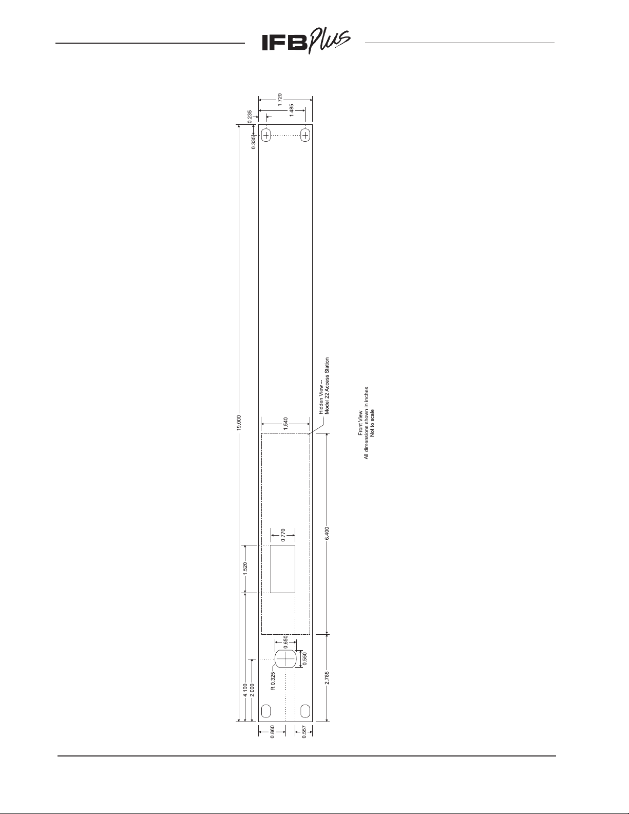
Figure 2. IFB Plus Series Model 25A 19-Inch Rack Adapter
(used with Model 22 Access Station and Model 11A Gooseneck Microphone)
Issue 7, November 2001 Model 2 User Guide
Page 52 Studio Technologies, Inc.
Page 53

Figure 3. IFB Plus Series Model 28A Panel Adapter
(used with Model 22 Access Station and Model 11A Gooseneck Microphone)
Model 2 User Guide Issue 7, November 2001
Studio Technologies, Inc. Page 53
Page 54

Figure 4. IFB Plus Series Model 22 Access Station Overall Dimensions
Issue 7, November 2001 Model 2 User Guide
Page 54 Studio Technologies, Inc.
Page 55
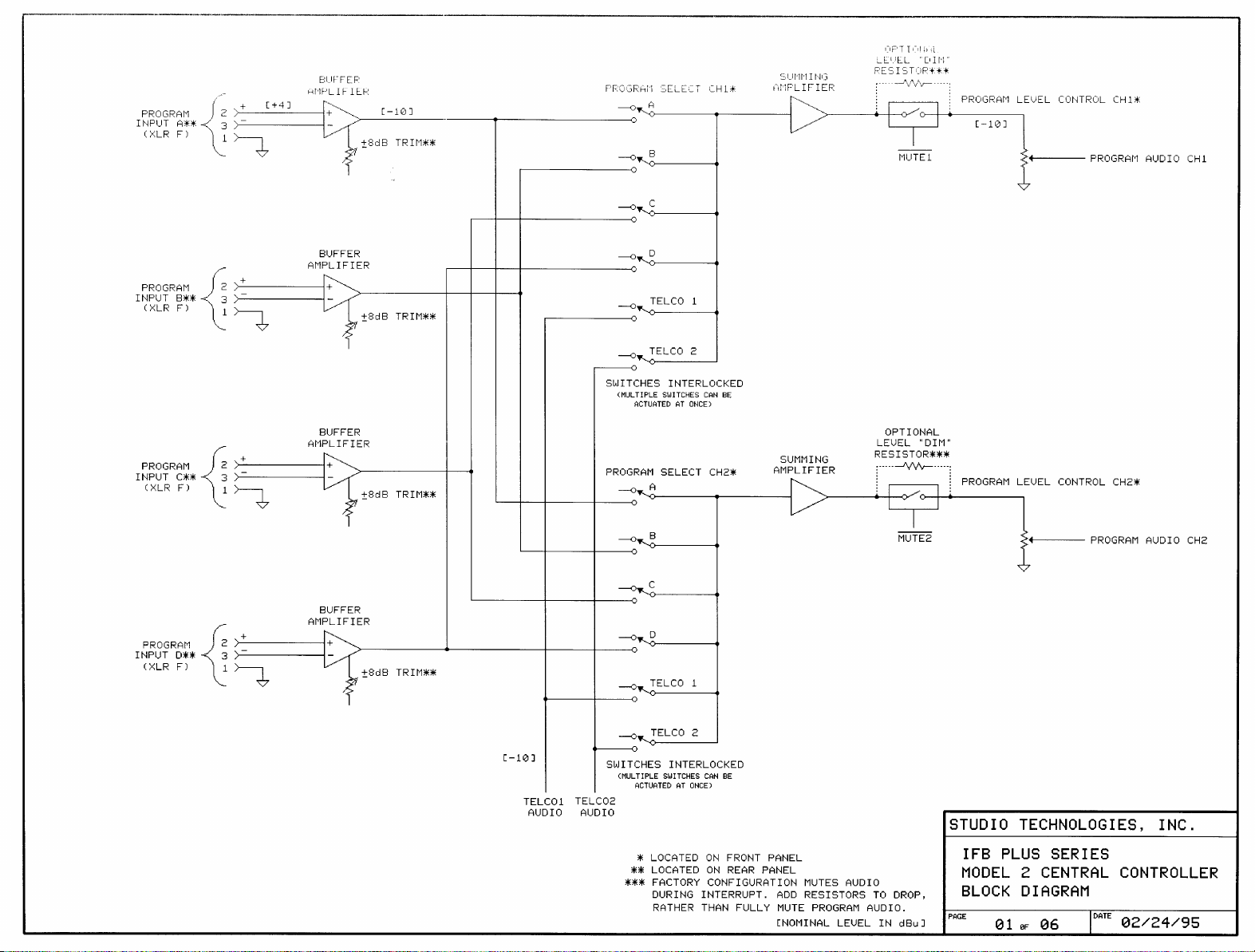
Page 56
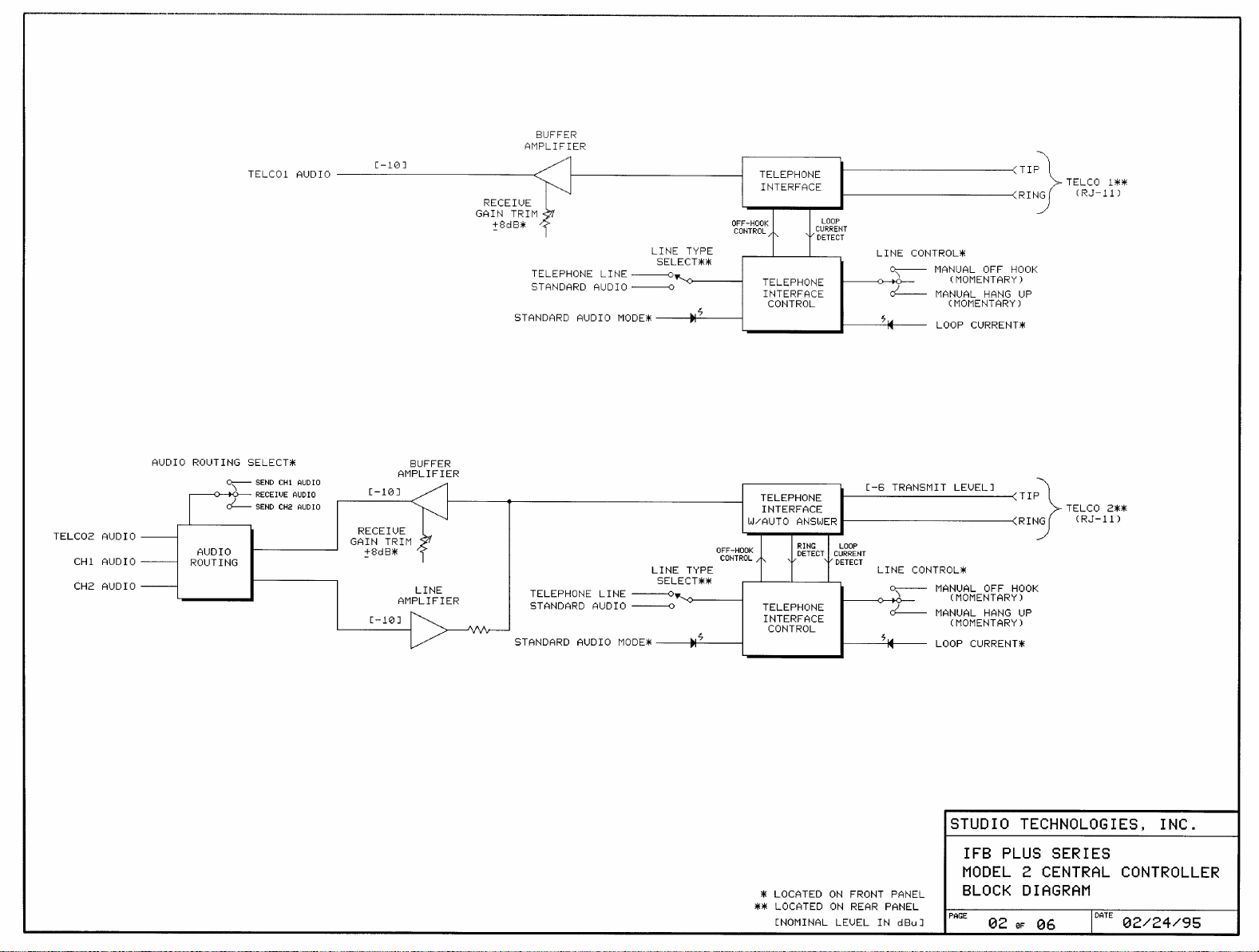
Page 57

Page 58
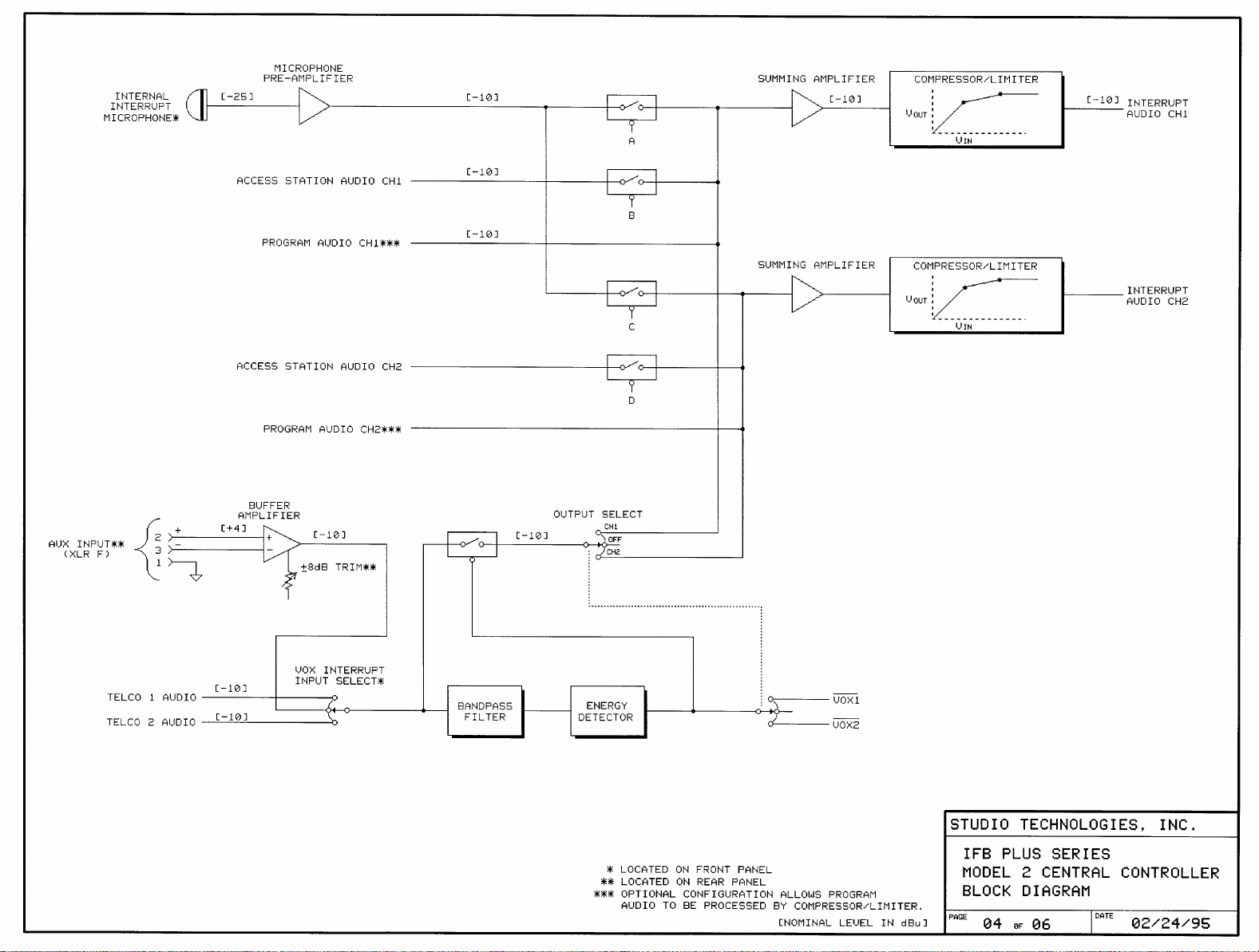
Page 59
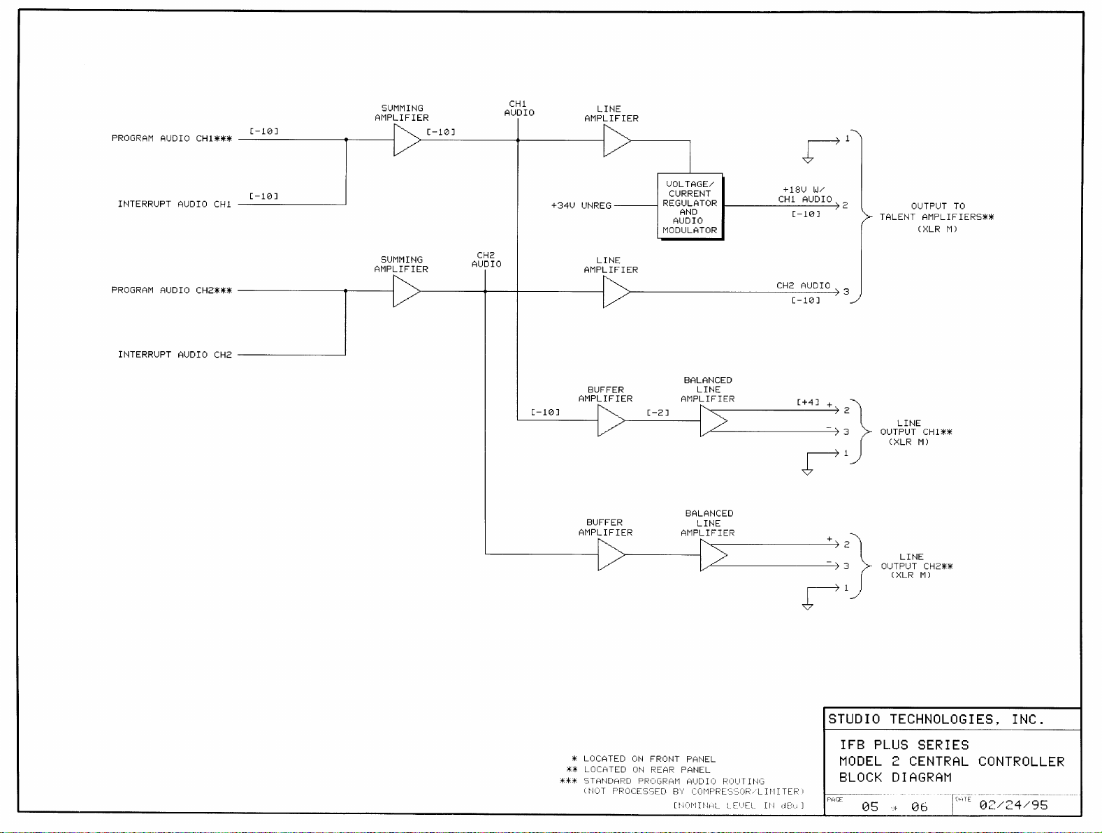
Page 60

Page 61

Page 62
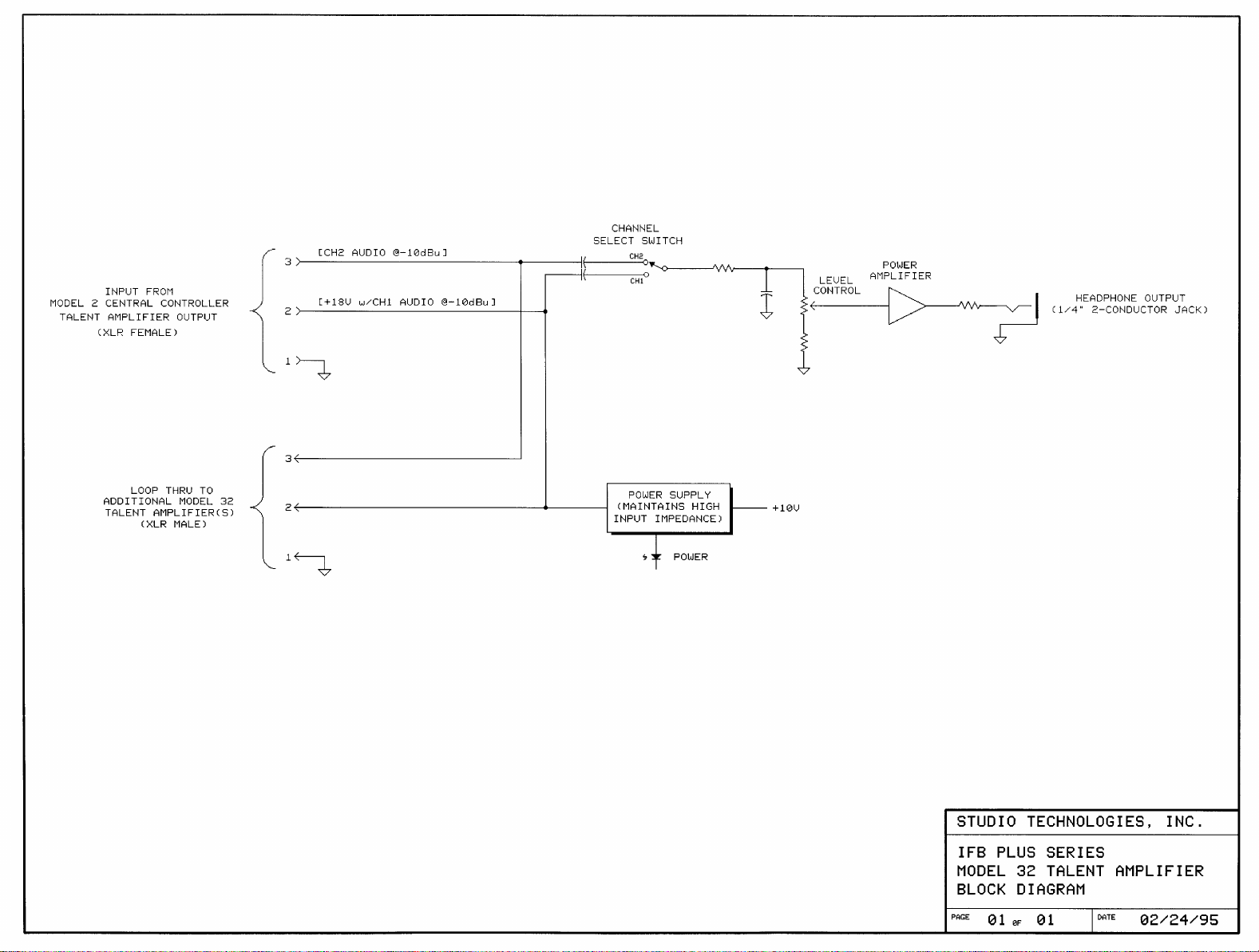
Page 63
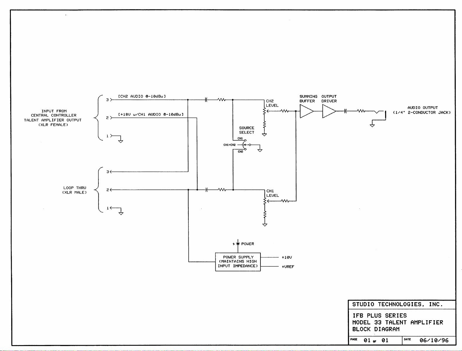
 Loading...