

Page 1

User Guide
Issue 3
This User Guide is applicable for serial numbers:
AN2-00251 and later
© 1998 Studio Technologies, Inc.
5520 West Touhy Avenue
Skokie, Illinois 60077 U.S.A.
Telephone (847) 676-9177
Fax (847) 982-0747
www.studio-tech.com
50011, Issue 3
Page 2

Table of Contents
Introduction.................................................................................. 5
Installation.................................................................................... 6
Operation..................................................................................... 7
Theory of Operation and Troubleshooting...................................1 0
Specifications...............................................................................13
Studio Technologies Limited Warranty........................................14
Figure 2 .........................................................Not included in PDF
Figure 3 .........................................................Not included in PDF
Schematic Diagrams ........................................Not included in PDF
AN-2 User Guide Issue 3
Studio Technologies, Inc. Page 3
Page 3

Introduction
The Studio Technologies AN-2 Stereo
Simulator has numerous applications within
recording, live performance, film and broadcast operations because of its ability to
create a simulated stereo signal from a
monophonic source. The AN-2 is also
capable of a number of audio effects centering on its ability to simulate stereo. The
stereo signal produced by the AN-2 is
completely mono compatible, so that it can
be remixed back to mono without the serious signal degradation often encountered
when remixing simulated stereo produced
by other equipment such as delay lines and
harmonizers. In addition, the AN-2 is
equipped with a proprietary circuit that
randomizes the non-reclusive filtering process, thereby avoiding the harmonic harshness that often results from stereo
simulation with delay lines.
Operational Description
To understand the operation of the AN-2,
it is useful to have a basic understanding
of the way stereo recording techniques can
fool the brain into believing it is hearing a
number of sound sources.
When two or more microphones are used
to record music, two effects are noticed
when the recording is played back over
two speakers. They are:
• Directional effects: These are due to
differences in arrival times at the ears and
the intensity differences of the various
frequencies that make up the music.
• Spaciousness imparted to the sound:
The sound is perceived as originating
from an area that is wider than the room
in which the listener is sitting. This
spaciousness is caused by the interaction
of the sounds that reach the microphones
directly and those sounds that reach the
microphones after being reflected from
the surfaces of the recording studio.
The degree of spaciousness of the recorded music coming from the two
speakers is dependent on the amount of
coherence (sameness or consistency)
between the signals fed to the speakers.
If the two channels are perfectly coherent
(the same signal fed to both speakers), the
sound heard is monaural and the source
of the sound seems to be midway between
the two speakers. As the signal fed to one
speaker begins to vary from the signal fed
to the other, the channels become incoherent and the spaciousness of the sound
increases. This effect is known as “imaging,” and results in the impression that each
instrument or voice is coming from a different point in space. The definition and clarity
of the sound sources seems to increase as
the imaging increases, up until the point
where the two channels become completely
incoherent, or different. At this point, the
stereo image collapses and there is no
spacial effect at all. What is heard, rather,
are two mono channels.
The AN-2 is designed to allow you to vary
the degree of coherence of the sound (and
the resultant amount of imaging) using the
depth and width controls, creating a simulated stereo signal from a monophonic
source. The two output signals of the AN-2
can be recombined, restoring mono.
AN-2 User Guide Issue 3
Studio Technologies, Inc. Page 5
Page 4
Mono Compatibility
In many applications, especially recording
and broadcast, it is critical that any stereo
signal produced can be summed (L+R)
without adverse effects. The AN-2 was
designed so that the simulated stereo signal
produced is completely mono compatible.
No setting of the controls or circuit anomalies ever produce a problem in this area.
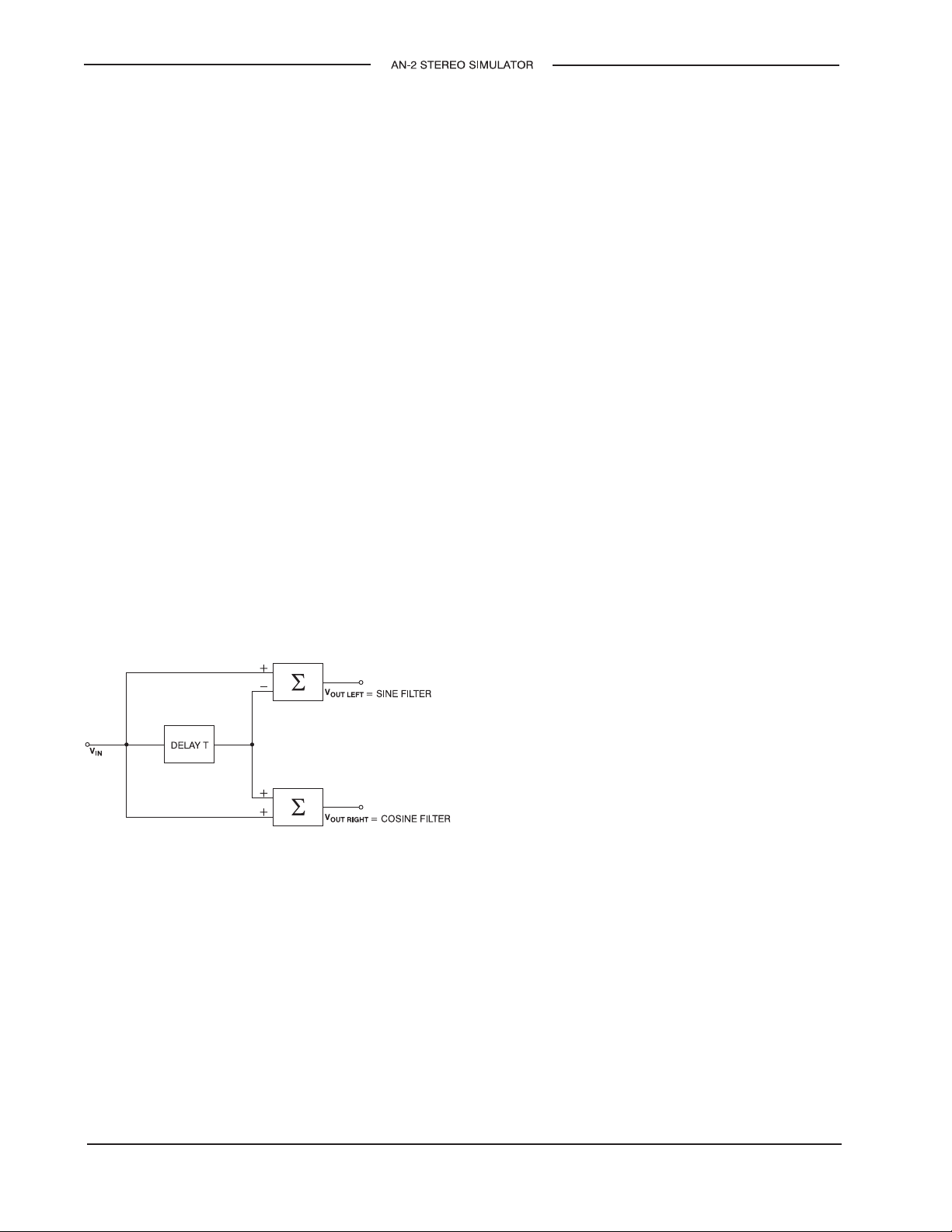
The AN-2 uses the classical technique of
creating comb filters, as shown in Figure 1.
The transfer function of the upper network
is H(z) = 1 – z
2/T, 3/T, etc. The lower network is merely
the complement of the upper; where the
upper network has an amplitude peak, the
lower has an amplitude dip. If the two outputs are summed, it can easily be seen that
the delay line is cancelled out, leaving only
the direct, or mono, unaltered signal.
Figure 1
For musical reasons, the AN-2 uses a
network after the delay line to randomize
the peaks and dips. However, the peaks
and dips are still interleaved and the mono
sum is also the same as the input signal.
–n
, resulting in dips at 1/T,
Installation
The AN-2 is rack-mountable, requiring one
1.75-inch (4.45cm) rack space. It weighs
five pounds (2.27kg), and operates on
either 115Vac or 230Vac. Refer to the
Specifications section for more complete
electrical and physical specifications.
Placement
If you wish to mount your AN-2 near other
equipment, make certain that it is not near
the power transformer of another unit. The
AN-2 is well shielded, but some of the
circuitry is sensitive to high levels of EMF
from outside sources.
Connecting the Unit to Power
The AN-2 may be operated from either
100-125 or 200-250Vac power, 50/60Hz.
Units shipped to North America are factory
selected for 115V operation and are supplied with a 0.5A 3AG fuse. Units shipped
outside North America are factory selected
for 230V operation and supplied with a
0.25A 5 x 20mm fuse. Before connecting
the AN-2 to power, determine the actual line
voltage and check to see that the voltage
selector switch (located on the back panel
of the unit) is set to the appropriate voltage.
Please note that an incorrect setting could
seriously damage the unit. Should it be
necessary to change the voltage selection,
insure that the correct fuse value is used:
0.5A for 115V, 0.25A for 230V.
The AN-2 utilizes an IEC standard connec-
tor to mate with the line cord. The line
cord supplied has a North American standard plug at one end and an IEC connector
at the other. In non-North American applications the plug must be cut off and an
Issue 3 AN-2 User Guide
Page 6 Studio Technologies, Inc.
Page 5

appropriate plug attached. The wire colors
in the line cord conform to the internationally recognized CEE color code and should
be wired accordingly.
Connection Wire Color
Neutral (N) Light Blue
Live (L) Brown
Earth or Ground (E) Green/Yellow
Audio Signal Connections
The input and output connectors of the
AN-2 are 3-pin XLR type. The input is
female and the outputs are male. Shielded
cable should be used when making connections. Proper phasing is very important if
you want to be able to remix the simulated
stereo back to mono. If the AN-2 is to be
used with unbalanced equipment, pins 1
and 2 of the outputs must be shorted together at the connectors which plug into
the back of the unit.
4) For use with a –10dBm input, set
switches 3 and 4 to the OFF position.
5) To achieve a –10dBm output, set
switches 1 and 2 to the OFF position
and short pins 1 and 2 of the output
connectors together.
To return the unit to +4dBm operation,
place all the switches in the ON position
and unshort pins 1 and 2 of the output
connectors.
Conver sion to +8dBm Le vel
For input and output levels of +8dBm, a
qualified technician must remove and replace seven resistors on the AN-2 circuit
board. Refer to the schematic for parts
values and locations. It is important that the
new resistors be 1% tolerance. A resistor
kit for –8dBm conversion is included with
the unit.
Operating Level
The AN-2 is shipped from the factory configured for input and output levels of
+4dBm. The unit can be set for –10 or
8dBm operation.
Use with –10dBm Semi-Pro
Equipment
If you wish to use the AN-2 with –10dBm
equipment, a special switch setting must be
made.
1) Disconnect the power cord.
2) Remove the top cover (two Phillips-head
screws on each side panel).
3) Locate the 4-position DIP switch on
the circuit board (slightly to the right of
center and labeled SW1).
Operation
Using the Controls
There are seven controls and one meter on
the front panel of the AN-2.
The Power switch controls AC power to the
unit.
The Gain control allows you to control the
input level, which is especially useful if you
are using a multi-track tape recorder which
lacks a gain control of its own. The peakreading meter (labeled “Level” on the front
panel of the unit) monitors the overall gain
structure. The gain control should be set so
that the meter’s yellow and green LEDs are
lit in the presence of a signal, with the red
LED lighting only on signal peaks. Attention
AN-2 User Guide Issue 3
Studio Technologies, Inc. Page 7
Page 6

to the peak-reading meter will give you the
best signal-to-noise ratio, while preventing
overload of critical circuitry.
The other four controls allow you to tailor
the stereo simulation to your tastes.
The Stereo Width control varies the number
of combs in each channel (refer to Figures
2 and 3). This changes the apparent spread
of the sound source. A single voice or
instrument should sound as if it originates
from a single point, while a group of voices
seems more natural when their sources are
apparently separate. Turning the control
fully clockwise increases this spreading
effect.
The peaks and dips in the frequency response curves shown in Figures 2 and 3
may seem abnormal when compared to
other equipment. Keep in mind that the
effect you are seeking is a result of the
interaction of the direct signal and the signal
reflected from the walls of a room. The
curves shown in Figures 2 and 3 approximate this interaction.
The Stereo Depth control affects the depth
of the combs. When rotated to the mono
position (fully counterclockwise), the combs
have no depth at all, giving a flat frequency
response. Rotated to full stereo (clockwise),
the combs reach their maximum depth,
giving the maximum stereo effect.
enhanced depth resulting from turning the
stereo depth control more fully clockwise.
The Modulation ON/OFF switch enables
and disables the modulation section. In the
out (OFF) position the modulation depth
and rate controls do not affect the signal.
The modulation controls (depth and rate)
produce an instantaneous change in pitch
similar to vibrato. The rate control varies
the speed of these changes from a slow
“chorus” to a fast warble. The depth control
varies the amount of the effect.
The setting of the modulation depth control
is related to the settings of the stereo width
and stereo depth controls. When the stereo
width and depth controls are set to a low
position (counterclockwise), the modulation
depth control should be raised (clockwise),
and vice versa.
The settings of all the controls are closely
interrelated. The best way to learn how the
unit sounds, of course, is to experiment. For
example, a string section might be best
enhanced with the stereo width set at two
o’clock, a stereo depth setting of one
o’clock, modulation depth at three o’clock,
and a minimum setting of the modulation
rate control. The settings outlined in this
and preceding paragraphs will give you a
good starting point; your finished product
will depend largely on your imagination.
This maximum effect may not be appropriate for your program material. If your signal
has few pitch changes (a single speaking
voice, for example), the combs may be
audible. Setting the stereo depth control to
eleven o’clock will give a natural stereo
effect without audible comb filter effects.
More complex sources, such as a vocal
group or full orchestra, will benefit from the
Issue 3 AN-2 User Guide
Page 8 Studio Technologies, Inc.
Recording Studio Applications
Although it may be placed almost anywhere
in the recording chain, for best results the
AN-2 should be between the source and the
final stereo mix.
When used with a typical console, the unit
should be fed from a track on the tape
recorder, or an unused cue or echo bus on
Page 7

the console. The outputs of the unit could
then be fed to a pair of console faders
panned hard left and hard right. It is neither
necessary nor desirable to add any source
signal to the mix, as the stereo depth control will accomplish this. Any equalization
should be placed upstream of the AN-2
(between the source and the unit).
Although the AN-2 was designed primarily
to simulate a stereo signal from monaural
sources, it has many practical applications
in the recording studio for the enhancement
of various vocal and instrumental signals.
For example, it is well known that using
a stereo pair of microphones to record a
soloist is subjectively more pleasing than
using a single microphone. Practical considerations usually make this recording configuration difficult because small movements of the soloist can result in disconcerting jumps when heard over two loudspeakers. The usual solution is to pan the soloist
center, but this creates the totally unnatural
condition of forcing the listener to “merge”
two identical signals coming from different
points in space. The AN-2 avoids both of
these problems by creating a stable stereo
image from a mono source.
The AN-2 can also be used to create a
subjectively “louder” signal from a mono
source, making it ideal for use with instruments such as bass guitar. How often have
you heard the words “more bass” from the
producer when the instrument is already
panned center and the meter is “in the red”?
Another application for the AN-2 in the
recording studio is to convert “tape slap” to
stereo; that is, to feed the output of the
delay line or tape machine into the AN-2
and mix the outputs of the AN-2 into the
stereo buses. The outputs of flangers,
chorus devices, echo chambers, and other
effects boxes can be converted to stereo in
the same way. Not only does the AN-2
enhance the effect, but the result is assured
of perfect mono compatibility. This is especially important for commercials, which will
most always be heard on radio and TV in
mono. This assures that the balance between for example, the reverb and the
program, will not change.
Hook-ups using external equalizers, mixers,
and filters may yield pleasing results that
you may not have expected. One example
would use cross-coupled equalizers after
the AN-2 outputs. The outputs of both the
EQs and the AN-2 are then mixed to form
two new output which are fed to the stereo
buses. The equalizers should have identical
boost and cut characteristics, or a mono
signal generated alter will suffer.
In practice, the boosted frequencies would
form center images, while the cut frequencies would have more stereo “spread.” Set
the stereo depth control fully clockwise for
this hook-up.
Remember:
When using a non-standard
connection, any operation or effect that is
performed on one channel must be equally
performed on the other. If not, mono compatibility will suffer.
As you become familiar with the operation
of the AN-2, you might want to try more
experimental uses, such as putting up an
ambience microphone in the studio during a
session and recording it on an extra track.
During mix-down, feed it through the AN-2
into your stereo mix. The result will be a
much more “live” feel to the sound.
AN-2 User Guide Issue 3
Studio Technologies, Inc. Page 9
Page 8

Broadcast and Film Applications
Television stations that are in the process
of converting to stereo can use the AN-2 to
process mono program material to stereo,
allowing full-time stereo programming. For
program material of a general nature containing speech and music, the stereo depth
control is best set about mid-range and the
stereo width control about three o’clock.
Programs consisting primarily of music can
benefit from more opening of the controls,
while programs that are mainly speech
should be processed with the controls less
open. The modulation control should not be
used for “on air” broadcasting. Leaving the
modulation ON/OFF switch in the OFF
position disables the modulation section;
if you want to be absolutely certain that the
modulation section will not be accidently
turned on, remove U15 (see schematic)
after disconnecting power to the unit.
AM and FM stereo radio stations will find
use for the AN-2 in converting old records
to stereo or “fattening” D.J. and announcer
voices. Again, careful use of the stereo
depth and width controls can result in optimum sound. Also, many commercials are
received by the station in mono and can be
enhanced by conversion to stereo.
The AN-2 can be employed in film studios
to remix mono movie sound tracks to stereo. Older music and sound effects libraries
can also be upgraded.
Theor y of Operation and
Troubleshooting
The following paragraphs describe the
theory of operation of the AN-2. This information will help you understand where a
failure may be located. Please read this
material before attempting to troubleshoot
the unit.
Theory of Operation
Refer to the schematic diagram of the AN-2
while reading this material.
U9 is a balanced input amplifier with a trim
potentiometer to obtain maximum common
mode rejection. Two sections of the DIP
switch, SW1, are used to select –10 or
+4dBm operation.
P5 is the input gain control, which is followed by a buffer amp. This amp sends a
portion of the input signal to U5, where the
two comb filters are produced by phase
addition and subtraction performed on the
delayed signal.
A pre-emphasis network precedes U11,
which acts as a compressor in a compandor
circuit. The compressor attack time is
speeded up by a charge pump U14, which
reduces transient distortion that is often
associated with compandors.
A 6-pole, 20kHz Butterworth filter removes
the possibility of audio frequencies aliasing
with the clock frequency from U1.
U6 acts as a bucket brigade delay line. The
line is driven by U2 and VCO U1, whose
frequency is set by the stereo width control,
P1.
Issue 3 AN-2 User Guide
Page 10 Studio Technologies, Inc.
Page 9

U15 is an LFO which modulates the VCO
via P2 (modulation depth control) and P3
(modulation rate control).
A 5-pole, 20kHz low-pass Butterworth filter
removes clock frequency from the output
signal.
Equipment Needed for
Troub leshooting
The AN-2 is constructed of high-quality
solid state components. Given normal use,
there is no need for regular preventive
maintenance.
The expander, U11, restores the dynamic
range, using another charge pump, U3, in
the expander rectifier.
A proprietary randomizing circuit, labeled
N1, assures that the peaks and dips in the
combs do not fall on harmonics, preserving
the natural sound of the music.
U17 comprises the peak-reading meter
circuit; it combines a rectifier and three LED
drivers.
U5 is a mixer, interleaving the combs on the
left and right outputs. If P4, the stereo depth
control, is set fully counterclockwise, any
delay signal is removed, leaving only the
direct signal. This will also happen if the two
outputs are summed externally, since the
delay signal will be cancelled. The switches
following this IC set the output levels.
The two output stages, U7 and U8, are
differential balanced line outputs with cross
coupled output sensing feedback. This
circuit gives an additional 6dB of headroom
for a given supply voltage, while maintaining
the output level and keeping the opamp
current draw at a safe level, even if one side
of the output is shorted.
The power supply is bipolar, using two IC
voltage regulators to provide low ripple
±15Vdc. Two additional decoupling stages
provide isolation for the clock circuitry.
If repair does become necessary, you may
either have a qualified technician service
the unit or return it to the factory. Contact
the factory for a return authorization number
should you wish factory repair. When returning your unit, be sure to pack it securely
and insure it for its replacement value.
If you decide to have a technician service
the unit, the following test equipment is
required to allow accurate troubleshooting
a component replacement:
• high-quality oscilloscope equipped with
balanced vertical and horizontal inputs
• low-distortion oscillator (.01%)
• harmonic distortion analyzer
• AC voltmeter with –80dBm sensitivity
• high-quality digital voltmeter
• adjustable attenuator box
• tone burst generator
• frequency counter
T roub leshooting and Alignment
WARNING:
be performed by a qualified technician.
Operating the AN-2 with the top and/or
bottom cover removed exposes the technician to points in the power input section with
hazardous voltages. USE CAUTION!
The following procedures must
AN-2 User Guide Issue 3
Studio Technologies, Inc. Page 11
Page 10

The first step in troubleshooting the AN-2 is
to remove the top cover (two Phillips-head
screws on each side panel), and check the
DC voltages at the test points listed on the
schematic. If this technique fails to pinpoint
the trouble, connect an oscillator to the
input and trace the signal (again, using the
schematic) until the source of the problem
is found. The following paragraphs will aid
in aligning the AN-2 circuits, which will
restore proper operation. It is important to
perform the alignment procedures whenever you have replaced a component in the
unit.
CAUTION:
DO NOT attempt to adjust any
of the trim pots inside the unit before you
understand the entire alignment procedure.
Improper or out-of-order adjustment may
destroy some of the integrated circuits.
U9
To achieve the best common-mode rejection, feed a 1kHz signal at +4dBm into the
input connector: high side to pins 2 and 3
(short 2 and 3 together), and low side to pin
1. Check the output at TP9, and set R89 for
a minimum signal.
U3 and U14
Set R110 to 1.34Vdc at TP8 with no input
signal. Feed a 1kHz input signal at +4dBm,
set gain control to read –10dBm at TP9,
and read the AC signal at TP7. Drop the
input signal exactly 20dB. The signal at TP7
should drop 15dB. If not, reset R110. Repeat this procedure several times, as R110
also affects the reference level.
U1
The clock frequency of this VCO should
vary between approximately 100kHz and
375kHz, depending on the setting of P1
(stereo width) when measured at TP1
(clock set). It should produce approximately
12V, measured peak-to-peak, at TP1.
Connect frequent counter between TP2
(clock set) and common. Set P1 (stereo
width) fully clockwise. Set SW2 (modulation
ON/OFF) to the OFF (out) position. Adjust
R97 so as to read 62kHz on the frequency
counter. If it is ever necessary to replace
U1, use only the part manufactured by
National Semiconductor.
U3 and U11
Set R5 to give 1.34Vdc at TP5 with no input
signal. Feed a 1kHz input signal at +4dBm,
with gain control set as before, and read the
AC signal at TP6. Drop the input signal
exactly 20dB. The signal at TP6 should
drop 20dB. If not, reset R5. Repeat this
procedure several times.
U6
Set R46 for minimum THD with P1 (stereo
width) set to midpoint. The input for this
procedure should be 5kHz at +4dBm.
U11
Using the tone burst generator, feed an
input signal to the unit of 1kHz at + 4dBm,
and set the gate duration for 2 cycles open
and 64 cycles closed. Set R82 for a flat
base band. If a tone burst generator is not
available, set R82 to midpoint.
Issue 3 AN-2 User Guide
Page 12 Studio Technologies, Inc.
Page 11

Verification of the specifications is accomplished by standard procedures with the
exception of the “noise” and “THD” measurements. Since the outputs are combs,
P1 (stereo width) should be rotated to give
the maximum possible output for the
frequency chosen. This measurement
becomes the reference level below which
the noise should measure 70dB. THD
should be measured in the same way.
Specifications
Mounting
One space in a standard 19-inch (48.3cm) rack
AC Mains Requirements
100 to 125Vac or 200 to 250Vac, switch selectable,
50/60Hz, 10 watts
Fuse
0.5A for 115V, 0.25A for 230V; units shipped to
North America use 3AG type; units shipped outside
North America use 5 x 20mm type
Connectors
Input: 3-pin XLR-type female, pin 3 hot
Outputs: 3-pin XLR-type male, pin 3 hot
Input
Balanced bridging, differential amplifier
Input Impedance
100k ohms, balanced
50k ohms, unbalanced
Maximum Input Level
+20dBm (re 0.775V RMS)
Frequency Response
±1dB, 30Hz to 15kHz, delay section
±1dB, 30Hz to 30kHz, direct section
Dynamic Range
90dB
Noise
70dB below operating level
Gain
8dB
Outputs
Balanced, differential amplifiers
Output Impedance
100 ohms
Maximum Output Levels
+26dBm into 10k ohms balanced (re 0.775V RMS)
+24dBm into 600 ohms balanced (re 0.775V RMS)
+22dBm into 10k ohms unbalanced (re 0.775V RMS)
+20dBm into 600 ohms unbalanced (re 0.775V RMS)
Distortion
Less than 0.2% at maximum operating level
AN-2 User Guide Issue 3
Studio Technologies, Inc. Page 13
Page 12

Environment
Operating: 32 degrees F to 122 degrees F
0 degrees C to 50 degrees C
Storage: –4 degrees F to 140 degrees F
–20 degrees C to 60 degrees C
Dimensions (Overall)
19.00 inches wide (48.3cm)
1.75 inches high (4.5cm)
7.00 inches deep (17.8cm)
Weight
5 pounds (2.3kg)
Specifications and information contained in this user
guide are subject to change without notice.
Studio T echnologies
Limited W arranty
The Studio Technologies, Inc. product
which you have purchased is guaranteed
against defects in material and workmanship under normal use and service for
a period of three (3) years from date of
manufacture.
During this warranty period, any components of the product that prove to be defective will be repaired (or, at the discretion
of Studio Technologies, Inc., replaced)
at no charge provided that the product
is returned, shipping prepaid, to the
manufacturer.
Information on obtaining service is available
by contacting the dealer from whom the
product was purchased, or by contacting
Studio Technologies, Inc.
This warranty does not apply if, in the opinion of Studio Technologies, Inc., the product
has been damaged due to abuse, misuse,
misapplication, accident or as a result of
service or modification by other than an
authorized dealer service center.
No other warranties are expressed or
implied, including, but not limited to,
any implied warranties of merchantability and fitness for a particular purpose.
Studio Technologies, Inc. shall not be
held responsible for any consequential
damages or losses arising from the use
of this product.
Issue 3 AN-2 User Guide
Page 14 Studio Technologies, Inc.
 Loading...